
W6000 - Network Equipment DELL - Free user manual and instructions
Find the device manual for free W6000 DELL in PDF.
| Product Type | Modular Wireless LAN Controller for enterprise network |
| Brand | Dell (licensed by Aruba Networks) |
| Model | PowerConnect W6000 |
| Dimensions (H x W x D) | 14.9 cm x 44.2 cm x 31.8 cm (3U rack form factor) |
| Maximum weight | 26.5 kg (chassis with 3 power supply modules) |
| Power supply | Up to 3 hot-swappable 400 W power supply modules (HW-PSU-400), input 85–264 V AC, 50–60 Hz, output 48 V / 8 A |
| Controller module slots | 4 slots for W-6000M3 modules (up to 512 access points per module) |
| Main functions | Layer 2/3 switch 10/100/1000 and 10GbE, load balancing, built-in security, centralized management, mobility, authentication, Air Monitors support |
| Network interfaces | 10/100/1000Base-T and 10GbE Ethernet ports (depending on installed modules) |
| Management | Web interface (HTML), serial console RJ-45/DB-9, command line |
| Cooling | Cooling module with 3 redundant fans, hot-swappable in less than one minute |
| Operating temperature range | 0 to 40 °C (alarms at 40 °C, 50 °C, 60 °C) |
| Operating humidity | 5 to 95% non-condensing |
| Maximum altitude | 3,048 m |
| Electrical safety | Complies with safety standards (high voltage, grounding, use of antistatic wrist strap) |
| EMC compliance | Class A (FCC, ICES-003, VCCI, EN55022/55024) – professional use only |
| Internal battery | Lithium battery (replacement by qualified technician only) |
| Maintenance and cleaning | Maintain a 10 cm clearance around the chassis for ventilation. Clean with a dry cloth or compressed air. |
| Spare parts and repairability | Hot-swappable modules (power supply, cooling, controller). No user-serviceable internal parts. Contact Dell for service. |
| Installation kit contents | Chassis, cooling module, rack mount kit, serial adapter, documentation |
Frequently Asked Questions - W6000 DELL
User questions about W6000 DELL
0 question about this device. Answer the ones you know or ask your own.
Ask a new question about this device
Download the instructions for your Network Equipment in PDF format for free! Find your manual W6000 - DELL and take your electronic device back in hand. On this page are published all the documents necessary for the use of your device. W6000 by DELL.
USER MANUAL W6000 DELL
Dell PowerConnect W-6000 controller
Installation Guide
Copyright
© 2011 Aruba Networks, Inc. AirWave®, Aruba Networks®, Aruba Mobility Management System®, and other registered marks are trademarks of Aruba Networks, Inc. Dell™, the DELL™ logo, and PowerConnect™ are trademarks of Dell Inc.
All rights reserved. Specifications in this manual are subject to change without notice.
Originated in the USA. Any other trademarks appearing in this manual are the property of their respective companies.
Open Source Code
Certain Aruba products include Open Source software code developed by third parties, including software code subject to the GNU General Public License (GPL), GNU Lesser General Public License (LGPL), or other Open Source Licenses. The Open Source code used can be found at this site:
http://www.arubanetworks.com/open_source
Legal Notice
The use of Aruba Networks, Inc. switching platforms and software, by all individuals or corporations, to terminate other vendors' VPN client devices constitutes complete acceptance of liability by that individual or corporation for this action and indemnifies, in full, Aruba Networks, Inc. from any and all legal actions that might be taken against it with respect to infringement of copyright on behalf of those vendors.
Preface....5
Overview of this Manual 5
Related Documents....5
Text Conventions 5
Contacting Support 6
Chapter 1 System Overview....7
Features 7
Physical Description....7
Chapter 2 Installing the Chassis....9
Pre-Installation Checklist....9
Precautions 10
Requirements 10
Minimum Configuration....10
Rack Mounting Kit....11
Selecting a Location....11
Rack Mounting the Chassis 12
Adding W-6000M3 Controller Modules....13
Connecting Power 14
Chapter 3 Verifying the Installation....15
Chapter 4 The Fan Tray....17
Features 17
Built-in Redundancy....17
Hot Swap....17
Physical Description....17
Replacing a Fan Tray 19
Prepare the New Fan Tray....19
Remove the Old Fan Tray 19
Insert the New Fan Tray....19
Chapter 5 Dell PowerConnect W-6000M3....21
Chapter 6 The W-6000 Power Supply Module 23
Features 23
Rating....23
Load Sharing 23
Redundancy....23
Hot Swap....23
Physical Description 24
Power Management 25
W-6000M3 Module and PSU Configuration Table 25
Inserting a Power Supply....25
Removing a Power Supply 27
Chapter 7
Specifications 29
Physical....29
Environmental 29
Operational 29
Compliance....29
Electromagnetic Interference 30
United States....30
Canada 30
Japan....30
Europe 30
Safety....30
Lithium Battery Notice....30
Laser Notice....31
The preface includes the following information:
• An overview of the sections in this manual
• A list of related documentation for further reading
- A key to the various text conventions used throughout this manual
• Dell support and service information
Overview of this Manual
This manual is for trained technicians responsible for installing the Dell PowerConnect W-6000 controller. The manual is organized as follows:
• The Dell PowerConnect W-6000 Controller Chassis
Chapters 1, 2, and, 3 describe the W-6000 controller, and provide instructions for mounting the chassis, attaching power, and performing initial power-on tests.
• The Dell PowerConnect W-6000M3 Controller Modules
Chapters 4, 5, and 6 focus on a specific module and include instructions for installing or replacing the individual item.
- Appendix
Related Documents
The following items are part of the complete documentation for the Dell system:
- Dell PowerConnect W-6000 Controller Installation Guide (this manual)
• Dell PowerConnect ArubaOS User Guide
• Dell PowerConnect W-AP Installation Guide
Text Conventions
The following conventions are used throughout this manual to emphasize important concepts:
Table 1 Text Conventions
| Italics This style is used to emphasize important terms and to mark the titles of books. | |
| System items This fixed-width font depicts the following:Sample screen outputSystem promptsFilenames, software devices, and certain commands when mentioned in the text | |
| CommandsIn the command examples, this bold font depicts text that the user must type exactly as shown. |
Table 1 Text Conventions
| In the command examples, italicized | text within angle brackets represents items that the user should replace with information appropriate to their specific situation. For example: # sendIn this example, the user would type “send” at the system prompt exactly as shown, followed by the text message they want to send. Do not type the angle brackets. |
| [ Optional ] In the command examples, items enclosed in brackets are optional. Do not type the brackets. | |
| { Item A | Item B } In the command examples, items | within curled braces and separated by a vertical bar represent the available choices. Enter only one choice. Do not type the braces or bars. |
Contacting Support
Table 2 Dell Contact Information
| Website | |
| Main Websitedell.com | |
| Support Websitesupport.dell.com | |
| Documentation Webitesupport.dell.com/manuals | |
The Dell PowerConnect W-6000 controller is an enterprise-class, modular chassis which connects, controls, and intelligently integrates wireless Access Points (APs) and Air Monitors (AMs) into the wired LAN.
This chapter introduces you to the W-6000 controller. It describes the general features of the modular system and illustrates key physical elements. Once familiar with the system, you can begin the installation process covered in the next chapter.
Features
This section outlines the general features of the W-6000 controller.
• 10/100/1000 Mbps and 10 Gbps Ethernet switch with high-speed Layer-2/Laver-3 packet forwarding.
- High-performance packet processing provides value-added wireless services such as load balancing, rate limiting, self-healing, calibration, authentication, mobility, security, and centralized monitoring and configuration.
• 3U chassis can be mounted in a standard 19-inch telecom or server rack.
- Modular, slot-based chassis allows for network expansion and fault-tolerance.
■ Up to 4 Dell PowerConnect W-6000M3 modules
■ Up to 3 hot-swappable power supplies with load sharing capability for redundancy
■ A fan tray containing three individual fans for redundancy
Physical Description
Figure 1 Dell PowerConnect W-6000 controller
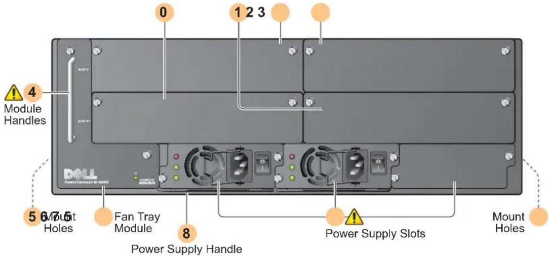
0 Slot 0: This slot is for the required Dell PowerConnect W-6000M3 Controller Module.
1 Slot 1: This slot for an additional W-6000M3 module.
2 Slot 2: This slot for an additional W-6000M3 module.
3 Slot 3: This slot for an additional W-6000M3 module.
4 Module Handles: All module handles are used only for removing and inserting the individual modules.

CAUTION: Never use the module handles to lift or move the W-6000 controller chassis. Using the handles to support the chassis can result in serious damage to both the module and the chassis.
5 Holes for attaching rack mounting brackets (on side)
6 Fan Tray Module: The W-6000 controller is cooled by the air pulled through the chassis by the fan tray. The fan tray pulls air from right to left (as viewed from the front of the chassis) across the installed modules.
During operation, the air vents on the left and right sides of the chassis must remain unobstructed by cables or mounting equipment. For proper air circulation, leave at least 10 cm (4 inches) of clearance on the left and right of the chassis.
7 Power Supply Slots: The chassis has slots for up to three power supplies. The number of power supplies required for your system depends on the number of W-6000M3 Controller Modules installed, and whether you wish to include redundant power supplies. See “Power Management” on page 25 for more information.
Each power supply has its own power cord and power switch.

CAUTION: Never insert or remove a power supply while its power switch is in the On position or while the power cord is plugged in. First verify the power switch is Off and the cord is unplugged.

CAUTION: Be sure to exercise proper Electrostatic Discharge (ESD) precautions when handling the Dell W-6000 controller and its components.
8 Power Supply Handle: Use this handle for removing or inserting a power supply.

CAUTION: Installation should be performed by a trained technician.
This chapter covers the following installation topics:
• Precautions to observe during installation
- Requirements for W-6000 controller components and rack mounting gear
- Selecting a proper environment for the W-6000 controller
• Mounting the W-6000 controller in a rack
- Connecting power to the W-6000 controller
Pre-Installation Checklist
You will need the following during installation:
• Dell PowerConnect W-6000 Controller
- Dell PowerConnect W-6000 Controller rack mounting hardware (included)
• Phillips or cross-head screwdriver
• 19-inch equipment rack, or equivalent
- 3U rack space with 10 cm (4 inches) clearance to the left, right, front, and rear of the rack
- Another person to help position the W-6000 controller.
• One power cord for each power supply, rated to at least 10 A with IEC320 connector
- Adequate power supplies and electrical power (see “Power Management” on page 25)
• Cool, non-condensing air 0 to 40 °C (32 to 104 °F): may require air conditioning
- Console terminal with RJ-45 or DB-9 serial port
• RS-232 serial cable with RJ-45 male connectors
- A serial adapter (included) if connecting to the console with DB-9
Precautions
CAUTION: Dangerous voltage in excess of 240VAC is always present while the Power Supply Module is plugged into an electrical outlet. Remove all rings, jewelry, and other potentially conductive material before working with this product.
Never insert foreign objects into the chassis, the power supply, or any other component, even when the power supplies have been turned off, unplugged, or removed.
Main power is fully disconnected from the W-6000 controller by unplugging all installed power supplies' power cords from their outlets. For safety, verify the power outlets and plugs are in easy reach of the operator.
Do not handle electrical cables which are not insulated. This includes any network cables.
To minimize electrical hazard, keep water and other fluids away from the product.
Comply with electrical grounding standards during all phases of installation and operation of the product. Do not allow the W-6000 controller chassis, network ports, power supplies, or mounting brackets to contact any device, cable, object, or person attached to a different electrical ground. Also, never connect the device to external storm grounding sources.
Installation or removal of the chassis or any module must be performed in a static-free environment. The proper use of anti-static body straps and mats is strongly recommended.
Modules must be kept in anti-static packaging when not installed in the chassis.
Do not ship/store this product near strong electro-magnetic, electrostatic, magnetic or radioactive fields.
Do not disassemble the chassis or any module. They have no internal user-serviceable parts. When service or repair is needed, see "Contacting Support" on page 6.
Requirements
Minimum Configuration
A Dell PowerConnect W-6000 Controller must include the following basic components:
• One W-6000 controller chassis
• One fan tray
• One W-6000M3 Controller Module in Slot 0 (purchased separately)
- At least two 400W power supplies

NOTE: The number of power supplies required depends on the number of W-6000M3 Controller Modules installed in the chassis (see "Power Management" on page 25).
The W-6000 controller is shipped with all required power supply and fan tray modules installed. Install the chassis as described in this chapter, and then see the subsequent chapters in this manual for instructions on installing each additional module.
Rack Mounting Kit
Using the included rack mounting kit, the W-6000 controller can be mounted in a standard 19-inch Telecom network equipment rack. The rack mounting kit contains the following parts:
- 6-32 x 1/4" Phillips Head Screws (6x, included)
- 12-24 x 5/8" Phillips Head Screws (4x, included)
Additionally, the W-6000 controller can be installed in a 19-inch server rack. Installation in a server rack requires the following included items:
- 6-32 x 1/4" Phillips Head Screws (6x, included)
• M6 x 20mm Phillips Head Screws (4x, included)
• M6 Cage Nuts (4x, included) or M6 Cage Clips (4x, included)
Figure 2 Rack Mounting Hardware (Telecom Kit Shown)

NOTE: The six 12-24 screws are intended for securing the chassis to the rack. Some racks require different screws which are not included. Verify that you have the correct screws or fasteners for your rack system before attempting to mount the chassis.
Selecting a Location
The W-6000 controller, like other network and computing devices, requires an “electronics friendly” environment.
- Reliable power
Verify that your electrical outlet is compatible with the W-6000 controller (HW-PSU-400) power supply, which is rated at 400 W total and is auto-ranging to accept 85 to 264 VAC, at 50 to 60 Hz.
The power cords must be rated to 10 A and conform to grounded electrical standards in the country where the product is operated.
Use of a power line conditioner or Uninterruptable Power Supply (UPS) can decrease or mitigate problems caused by power service fluctuations. Verify that the output of any power shaping device is compatible with the W-6000 controller power supplies based on the information provided above.
• Cool, non-condensing ventilation
For proper operation, the W-6000 controller requires an environment with an ambient air temperature between 0 and 40 °C (32 to 104 °F). Humidity must be kept at non-condensing levels between 5 and 95%.
Where a large number of electrical devices are working in the same area, additional air conditioning or air circulation equipment may be required.
- Ample space
For proper air circulation, leave at least 10 cm (4 inches) clearance for the vents on the left, right, front, and rear of the chassis.
Leave additional space in front of the chassis to access power cords, network cables, and indicator LEDs.
• Limited electromagnetic interference

For best operation, keep the W-6000 controller and all cords and cables at least 0.7 meters (2 feet) from fluorescent lighting fixtures, and 2 meters (6 feet) from photocopiers, radio transmitters, electric generators, and other sources of strong electromagnetic interference.
Rack Mounting the Chassis
- Verify that your rack environment meets requirements (see "Selecting a Location" on page 11).
- Attach the rack mounting brackets to the chassis as shown in Figure 3 on page 12.
Figure 3 Attaching the Rack Mounting Brackets

The bracket marked with slot numbers 1 and 3 is for the right-hand side of the W-6000 controller chassis. Orient both brackets so that the narrow flange faces the front. When placed properly, the brackets' large rectangular voids will be positioned over the side vents to allow proper air flow during operation.
Use a Phillips or cross-head screwdriver to attach each bracket securely with four 6-32 flat head screws (included).
- Attach the W-6000 controller to the rack.

CAUTION: To avoid personal injury or damage to equipment, get help for lifting and positioning the W-6000 controller. Also, do not install the W-6000 controller in any fashion where instability or uneven mechanical loading may occur.

NOTE: For proper operation, the W-6000 controller requires an ambient air temperature between 0 and 40 °C (32 to 104 °F). Verify your rack environment is in compliance.
If you are installing this device in a server rack, install the cage nuts/clips first. Install the cage nuts/clips by completing the following steps:
a. Begin by inserting the lower lip of the cage but over the square opening in the back of the rail.
b. Insert the small end of the cage-nut installation tool through the opening in the rail (from the front), and hook the tool over the top lip of the cage nut.
c. Push the cage nut in towards the rail while rotating the tool up and pulling the tool back toward you until the top lip of the cage nut snaps into position.
d. Continue installing the W-6000 controller as normal.
Position the chassis in the equipment rack and align the brackets' mounting holes with the corresponding holes in your rack frame.
Figure 4 Mounting the W-6000 controller

Use a Phillips or cross-head screwdriver to secure the chassis to the rack with three 12-24 screws (for telecom rack) or three M6 x 20mm (for server rack) for each mounting bracket.

NOTE: Some cabinets require different screws which are not included. Verify that you use the correct screws or fasteners for your rack system.
Adding W-6000M3 Controller Modules
If you have received your modules separately from the chassis, or wish to expand the system with additional modules, see the subsequent chapters of this manual for specific instructions on installing each module.

NOTE: By adding modules, you are increasing the total power load. Depending on the modules installed, you may be required to add power supplies to the chassis and/or increase the capacity of your site's electrical systems. For details, see "Power Management" on page 25.
Connecting Power

CAUTION: This procedure should be performed by a trained technician.
- Verify you understand the procedure and all precautions.
Before beginning, read the entire procedure. Verify you understand all the precautions in these steps as well as those on page 10. - Verify that the installed power supplies can handle the power load.
The number of power supplies required for your W-6000 controller depends on the number of W-6000M3 Controller Modules installed. See “Power Management” on page 25 for details. - Verify that your site's electrical systems can handle the W-6000 controller's power load.
- Each W-6000 controller power supply (IIW-PSU-400) is rated at 400 W total and is auto-ranging to accept 85 to 264 VAC, at 50 to 60 Hz.
Depending on the total power load, you may be required to increase the capacity of your site's electrical systems. See “Power Management” on page 25 for details.

NOTE: Use of a power line conditioner or Uninterruptable Power Supply (UPS) can decrease or mitigate problems caused by power service fluctuations. Verify that the output of any power shaping device is compatible with the W-6000 controller power supplies based on the information provided above.
- Verify the power switch on the power supply is in the Off (○) position.

CAUTION: Never attach a power cord to a power supply while its power switch is in the On (I) position. Verify the power switch is Off (O) first.
- Attach the power cord to the power supply.
Plug an appropriate power cord into the power input socket. The socket accepts a power cord with a standard IEC320 plug.

CAUTION: For proper safety and performance, the power cord must be rated to 10 A and conform to grounded electrical standards in the country where the product is operated.

NOTE: The 400 W power supply (HW-PSU-400) includes a power cord retaining clip. When the power cord is attached, the clip can be used to hold the cord in place and help prevent it from being pulled out accidentally (see Figure 8 on page 26).
- Attach the power cord to a proper electrical outlet.

CAUTION: For safety reasons, verify the power outlets and plugs are within easy reach of the operator and can be quickly disconnected if necessary.
Repeat the above Steps 4, 5, and 6 for each installed power supply.
Once power is connected, you can perform the power-on test (see page 15).
Once the W-6000 controller is physically installed, run the following power-on test:
- Turn on all installed power supplies in quick succession.
For each power supply, place the power switch in the on ( | ) position.

NOTE: To avoid overloading the first power supplies to be turned on, all required power supplies should be turned on at roughly the same time (within about three seconds).
- Check for the proper power indicators.
Immediately upon power up, you should observe the following:
■ All power supply AC OK and DC OK LEDs light solid green.
- The fan tray Fan Status LED is solid green and you should be able to feel significant airflow blowing from the chassis vents at each of the three fan positions.
- Check for the appropriate operation indicators.
Once the system has successfully booted, you should observe the following:
■ The power supply AC OK and DC OK LEDs are still solid green.
■ The fan tray Fan Status LED is still solid green.

NOTE: For more information on LED behavior, refer to the individual chapters for the specific modules.
- Once the system has passed the initial power-up test:
■ Connect appropriate network cables. - You are now ready to perform the initial setup as described in the Aruba Quick Start Guide (which is included in the Accessory Kit) for the software loaded on your controller.
The Dell PowerConnect W-6000 controller Fan Tray (HW-FT) provides air circulation for cooling the W-6000M3 modules in the Dell PowerConnect W-6000 controller chassis and is required for their normal operation. Normal operating temperature for the W-6000 controller chassis is between 0 to 40 °C (32 to 104 °F). If this temperature range is exceeded, the W-6000 will provide a warning through the software to alert users of the change. The following table describes these alarms and their thresholds:
Table 3 Temperature Thresholds
| Alarm Severity Threshold | |
| Minor 40 °C | |
| Major 50 °C | |
| Critical 60 °C | |
This chapter describes the general features and physical characteristics of the fan tray, and provides instructions for replacing the module if necessary.
Features
Built-in Redundancy
Three fans are provided in the fan tray. The module is designed to provide for cooling, even if one fan fails. Any two operating fans will provide enough airflow for proper cooling until the fan tray can be replaced.
Hot Swap
Hot swapping should be performed by a trained technician. Hot swapping allows you to replace the fan tray without having to shut down the system. During the replacement operation, the chassis will continue to function without fans, though the procedure must be completed within one minute to resume proper cooling.
Physical Description
The fan tray slot is located on the left side of the W-6000 controller chassis and extends from the front of the chassis to the back.
Figure 5 Dell W-6000 controller Series Fan Tray
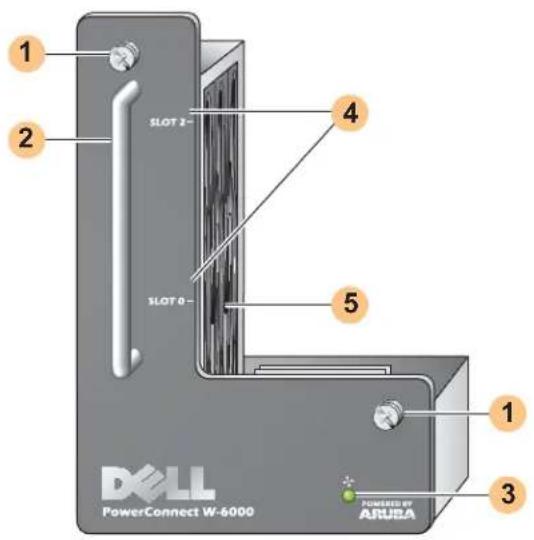
1 Module Fastening Screws: These captive screws are used for securing the module into the chassis fan tray slot.
2 Module Handle: This handle is used for removing or inserting the module into the chassis.

CAUTION: Do not use the fan tray handle to lift or move the W-6000 controller. Serious damage could result.
3 Fan Status LED: During operation, the Fan Status LED provides the following information:
Table 4 Fan Tray LED Behavior
| Status Description | |
| Off The fan | tray is not operating. |
| Green The | fan tray is receiving power and all three fans are operating properly. |
| Amber | One fan has failed, but the remaining two can provide proper cooling until the fan tray can be conveniently replaced. |
| Red Two or | more fans have failed. Replace the fan tray immediately. |

NOTE: In addition to the LEDs, the fan tray status and overall chassis temperature can be viewed using the CLI.
4 Slot Labels: When the fan tray is installed in the W-6000 controller, these labels name the module slots to the immediate right of the fan tray (see Figure 1 on page 7).
5 Fans (on side): Three independent fans provide redundancy for cooling the W-6000 controller cards.
Replacing a Fan Tray

CAUTION: Many repairs may only be done by a certified service technician. You should only perform troubleshooting and simple repairs as authorized in your product documentation, or as directed by the online or telephone service and support team. Damage due to servicing that is not authorized by Dell is not covered by your warranty. Read and follow the safety instructions that came with the product.
If hot swapping the fan tray, please be aware that there are time-critical aspects to parts of the procedure. To ensure proper preparation, please read through all the steps in the procedure before attempting the replacement. Also, make sure you understand all the precautions in these steps as well as those on page 10.
Prepare the New Fan Tray
- Unpack the new fan tray.
- Inspect the new fan tray to verify that it is undamaged.
- Place the new fan tray in a safe, accessible place near the chassis, ready for prompt insertion.
- Locate a #2 Phillips or cross-head screwdriver.
Remove the Old Fan Tray
- Loosen the fan tray's fastening screws.
At the front of the W-6000 controller, use the screwdriver to loosen both of the fastening screws on the faceplate of the installed fan tray. The screws loosen with counter-clockwise rotation, but are captive and cannot be fully removed. - Disengage the fan tray.
Grasp the module handle firmly and draw the fan tray forward from its slot. There may be moderate resistance as the module comes free from its connections with the chassis backplane, but do not use excessive force.
When the module is fully disengaged from the backplane, power to the working fans is lost and they will gradually stop spinning.
CAUTION: The fans will continue to spin for a short while, even though there is no power to them. Wait for the fans to stop spinning before removing the fan tray.

Also, when hot swapping, once the fans stop spinning, the W-6000 controller will continue to operate, though heat will begin to build in the operational components. From this point, there is a limited time (one minute) before installation of the new fan tray must be completed.
The one minute limit must be adhered to since the W-6000 controller does not have a thermal shutdown function. If you cannot replace the fan tray within one minute, shut down the controller.
- Once disengaged, the fan tray should easily slide out of the chassis. Fully remove the fan tray and place it safely aside.
Insert the New Fan Tray
- Pick up the new fan tray by the handle provided on its front panel.
- Carefully insert the fan tray into the chassis fan tray slot.
Align the rear of the fan tray with the guide rails in the chassis fan tray slot and slide it gently toward the backplane. The module should slide in easily most of the way. - Engage the fan tray.
As the fan tray reaches the back of the chassis, moderate resistance may be felt. Press firmly so the connectors at the back of the module engage with the backplane, but do not use excessive force.
When hot swapping the fan tray and when the connectors are properly engaged, power to the fans should be restored and they should start spinning.
- Check the fans to verify all of them are working.
Once power has been restored to the fan tray, either by engaging the module to the backplane during hot-swap or by turning on system power after a cold-swap, the Fan Status LED should be green and you should be able to feel significant airflow blowing from the chassis vents at each fan position.
If the fans are all working, this ends the time critical portion of the hot-swap procedure.
If one of the fans in a newly hot-swapped fan tray does not work (yellow Fan Status LED), allow at least three minutes for the remaining fans to cool the chassis before attempting another hot-swap replacement.

CAUTION: If two or more fans in the newly hot-swapped fan tray do not work (the Fan Status LED is red), shut down the W-6000 controller, replace the fan tray, and allow the W-6000 controller at least five minutes to cool before turning it back on.
- Secure the fan tray.
Use the screwdriver to push in and tighten both of the fastening screws on the faceplate of the newly installed fan tray. Rotate the screws clockwise until moderate resistance is felt, but do not over-tighten.
The Dell PowerConnect W-6000M3 is a hot-swappable controller module for use within a W-6000 controller chassis system. The W-6000 controller chassis is capable of containing up to four modules, each of which can be configured as a master or local. For complete details regarding the W-6000M3, including installation instructions and compatibility and configuration options, refer to the Dell PowerConnect W-6000M3 Installation Guide. For power management details, refer to “Power Management” on page 25.
Each W-6000M3 controller module is capable of supporting up to 512 campus connected APs with the use of Dell AP upgrade licenses. Contact your Dell sales representative for a complete listing of available software licenses.
For information on the installation and operation of the Dell PowerConnect W-6000M3 controller module, see the Dell PowerConnect W-6000M3 Controller Module Installation Guide that is included with each module.
The Dell PowerConnect W-6000 controller Power Supply adapts electrical power for use with the W-6000 controller. The W-6000 chassis has three slots that can hold individual power supplies to support load sharing and fault tolerance.
This chapter describes the general features and physical characteristics of the power supply and important power consumption management information. The final sections of the chapter cover the steps required to insert and remove power supplies.
Features
Rating
The Dell W-6000 Power Supply (HW-PSU-400) is rated at 400 W total output and is auto-ranging to accept 85 to 264 VAC, at 50 to 60 Hz. Up to three 400 W power supplies can be installed in the W-6000 controller.
Load Sharing
Load sharing occurs when more than one power supply of the same rating are installed in the W-6000 controller and turned on. Load sharing divides the total power load of the W-6000 among all plugged in power supply modules. Since the power supplies work together, the effective power capacity of the chassis is increased by with each additional power supply.
Redundancy
When multiple power supplies are installed, if one becomes unavailable (fails, or is turned off or removed) the remaining power supplies will attempt to provide full power for the W-6000 controller. If the total power load does not exceed the combined rated output of the remaining, operational power supplies, the W-6000 will continue to operate. For more information on power supply configurations, “Power Management” on page 25.
Hot Swap
Hot swapping should be performed by a trained technician. Hot swapping allows you to replace one failed power supply while the others provide full power. This makes it unnecessary to shut down the W-6000 controller during the replacement procedure.
Hot swapping requires that after the target power supply is removed, the chassis's total power load does not exceed the combined rated output of the remaining power supplies.
Physical Description
Figure 6 400W Power Supply
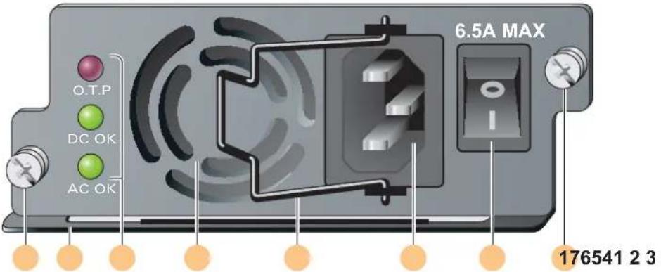
1 Module Fastening Screws: These two captive fastening screws hold the power supply in place in the chassis.
2 Module Handle: This handle is used for removing or inserting the module into the W-6000 chassis.

CAUTION: Do not use the power supply handle to lift or move the W-6000 controller. Serious damage could result.
3 Indicator LEDs
Table 5 400W Power Supply LEDs
| LED Name Position Status Description | |||
| O.T.P. (Over Temp. Protection) | Top Off | Power supply temperature is okay. | |
| Red | Power supply fan has failed or temperature is too high. | ||
| DC OK | Middle | Green | DC power output is okay. |
| Red | DC power output is not within tolerance. | ||
| AC OK | Bottom | Green | AC power input is okay. |
| Red | AC power input is not within tolerance. | ||

NOTE: In addition to the LEDs, the power supply status can be viewed using the CLI.
4 Air Intake Vent: This air intake vent helps the internal fan cool the power supply during operation. To prevent blockage, keep all material at least 10 cm (4 inches) from the vent.
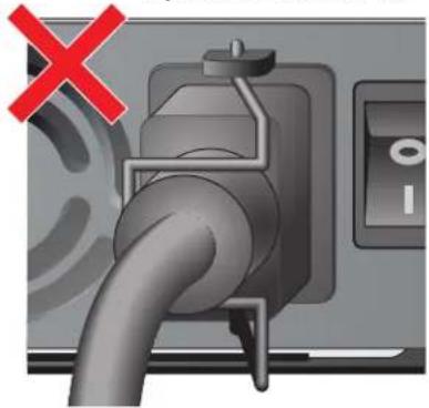
5 Power Cord Retaining Clip: This clip fits over the power cord once the plug has been inserted into the power input socket. It helps prevent the power cord from being pulled out accidentally.

CAUTION: Do not use the power cord retaining clip to remove the power supply module, or to lift or move the W-6000.
6 Power Input Socket: This power socket accepts power cords with standard IEC320 connectors. For proper safety and performance, the cord must be rated to 10 A and conform to grounded electrical standards in the country where the product is used.

Power Switch: The power switch has two states: Off (○) and On (|).
Power Management
The W-6000 controller supports up to three 400 W power supplies. If using one to two primary power supplies for 400 to 800 W of primary power, the use of a 400 W redundant power supply is possible.
For maximum capacity planning, add the maximum power draw required for all of the modules in your chassis configuration to determine the required number of power supplies.
W-6000M3 Module and PSU Configuration Table
The following table displays the W-6000M3 module configurations, and the resultant power supply configurations and power usage.
Table 6 Power Supply and Module Configurations
| Module Number of Units | ||||
| W-6000M3 Controller Module(130 W max power draw each) | 1 | 2 | 3 | 4 |
| Total Power Drawn (W) 130 260 390 520 | ||||
| Required number of PSUs 1 1 | 1 | 2 | ||
| Redundant number of PSUs 1 or 2 1 or 2 1 or 2 1 | ||||
Inserting a Power Supply
CAUTION: Many repairs may only be done by a certified service technician. You should only perform troubleshooting and simple repairs as authorized in your product documentation, or as directed by the online or telephone service and support team. Damage due to servicing that is not authorized by Dell is not covered by your warranty. Read and follow the safety instructions that came with the product.
- Verify you understand the procedure and all precautions.
Before beginning, read the entire procedure. Verify you understand all the precautions in these steps as well as those on page 10.
- Select a power supply slot for the power supply.
The 400 W power supply (ITW-PSU-400) can be installed in any power supply slot and any power supply slot can be left empty. That is, there is no specific required order of slots used for power supplies.
Figure 7 400 W Power Supplies Installed

natural_image
Diagram of a multi-chamber electronic device with indicator lights and ports (no text or symbols)If replacing a previously installed power supply, first see "Removing a Power Supply" on page 27.
If you are installing a power supply in an empty slot, you may have to remove the blank cover plate first. To do this, use a #2 Phillips or cross-head screwdriver. Turn the captive fastening screws on the faceplate counterclockwise until they are loose (they cannot be completely removed). Remove the cover plate and store it in a safe place.
- Verify the power switch on the power supply to be installed is Off (○).

CAUTION: Never insert or remove a power supply while its power switch is in the On (I) position or if the power cord is plugged into the power supply module. Verify the power switch is Off (O) first and that the power cord is unplugged from the W-6000 PSU module.
- Insert the power supply into the chassis.
Grasp the power supply by the handle attached along the bottom side of the power supply, keeping the LEDs on the left and power switch on the right. Do not use the power cord retaining clip to insert or remove the power supply. Align the back of the module with the guide-rails in the chassis power supply slot and gently slide the module toward the backplane. Do not force the module; it should slide in easily most of the way. There may be moderate resistance when the power supply meets the connectors at the back of the chassis. Press firmly to engage the connectors, but do not use excessive force.
- Secure the power supply.
Use the screwdriver to push in the module's captive fastening screws and turn them clockwise until moderate resistance is felt. Do not over-tighten.
- Attach the power cord to the power supply.

NOTE: Swing the cord retaining clip to the left before attaching the power cord.
Plug an appropriate power cord into the power input socket. The socket accepts a power cord with a standard IEC320 plug.

CAUTION: For proper safety and performance, the power cord must be rated to 10 A and conform to grounded electrical standards in the country where the product is operated.
- Secure the power cord.
When the power cord is attached, swing the power cord retaining clip to the right as shown in Figure 8 on page 26. This will hold the plug in place and help prevent it from being removed accidentally.
Figure 8 Using the Power Cord Retaining Clip

- Attach the power cord to a proper electrical outlet.
Verify that your site's electrical systems can handle the power load for the W-6000.
- Each power supply (HW-PSU-400) is rated at 400 W total and is auto-ranging to accept 85 to 264 VAC, at 50 to 60 Hz.

Depending on the W-6000's total power load, you may be required to increase the capacity of your site's electrical systems. See "Power Management" on page 25 for details.

CAUTION: For safety reasons, verify the power outlets and plugs are within easy reach of the operator and can be quickly disconnected if necessary.
NOTE: Use of a power line conditioner or Uninterruptable Power Supply (UPS) can decrease or mitigate problems caused by power service fluctuations. Verify that the output of any power shaping device is compatible with the W-6000 controller power supplies.
Removing a Power Supply

CAUTION: Many repairs may only be done by a certified service technician. You should only perform troubleshooting and simple repairs as authorized in your product documentation, or as directed by the online or telephone service and support team. Damage due to servicing that is not authorized by Dell is not covered by your warranty. Read and follow the safety instructions that came with the product.
- Verify that you understand the procedure and all precautions.
Before beginning, read the entire procedure. Verify that you understand all the precautions in these steps as well as those on page 10. - Verify that the power switch on the power supply to be removed is in the Off (○) position.

CAUTION: Never insert or remove a power supply while its power switch is in the On (I) position. Verify the power switch is Off (O) first.
- Unplug the power supply to be removed.
If using the power cord retaining clip, first swing it to the left and free of the plug. Then remove the plug. - Remove the power supply.
Use a #2 Phillips or cross-head screwdriver to turn the power supply's captive fastening screws counterclockwise until they are loose (they cannot be completely removed). Firmly grasp the handle of the power supply and carefully pull the module out of the chassis. - Cover blank slots.
For safety considerations, as well as to promote proper air flow for cooling and to prevent dust from entering the chassis, cover any unoccupied slot with a blank cover plate.
Physical
Table 7 Physical Specifications
| Item Measurement | |
| Size Height 14.9 cm (5.85 inches) | Width 44.2 cm (17.4 inches)Depth 31.8 cm (12.5 inches) |
| Weight 26.5 KG (58 lbs.) maximum | 6.3 KG (13.9 lbs.) chassis and fan tray4.4 KG (9.6 lbs.) each power supply |
Environmental
Table 8 Environmental Specifications
| Item Measurement | |
| Temperature Operating: 0 to 40 °C (32 to 104 °F) | Storage: 0 to 50 °C (32 to 122 °F)Minor alarm: 40 °CMajor alarm: 50 °CCritical alarm: 60 °C |
| Humidity 5% to 95% (non-condensing) | |
| Altitude 3,048 m (10,000 feet), maximum | |
Operational
Table 9 Operational Specifications
| Item Measurement | |
| Power Supplies Model HW-PSU-400— | Input: 85-264 VAC, 50-60 HzOutput: 48 V, 8 A |
| Power Consumption 460W (per power supply), maximum | |
| Network Management HTML Web-browser interface | |
| Standards IEEE 802.1x, IEEE 802.3 10BASE-T, IEEE 802.3u | 100BASE-TX, IEEE 802.3ab 1000BASE-T, IEEE 802.3z 1000BASE-SX |
Compliance
Electromagnetic Interference
United States
FCC Class A
This equipment has been tested and found to comply with the limits for a Class A digital device, pursuant to Part 15 of the FCC Rules. These limits are designed to provide reasonable protection against harmful interference when the equipment is operated in a commercial environment. This equipment generates, uses, and can radiate radio frequency energy and, if not installed and used in accordance with the instruction manual, may cause harmful interference to radio communications. Operation of this equipment in a residential area is likely to cause harmful interference in which case the user will be required to correct the interference at their own expense.
Any changes or modifications not expressly approved by the party responsible for compliance could void the user's authority to operate this equipment.
This product complies with Part 15 of the FCC Rules. Operation is subject to the following two conditions: (1) this device may not cause harmful interference, and (2) this device must accept any interference received, including interference that may cause undesired operation.
Canada
This digital apparatus does not exceed the Class A limits for radio noise emissions from digital apparatus as set out in the interference-causing equipment standard entitled “Digital Apparatus,” ICES-003 of the Department of Communications.
This device complies with Part 15 of the FCC Rules. Operation is subject to the following two conditions: (1) this device may not cause harmful interference, and (2) this device must accept any interference received, including interference that may cause undesired operation.
This Class A digital apparatus complies with Canadian ICES-003.
WARNING: This is a Class A product. In a domestic environment, this product may cause radio interference in which case the user may be required to take adequate measures.
This product complies with EN55022 Class A and EN55024 standards.
Safety
Lithium Battery Notice
This product contains a lithium battery which is replaceable only by a trained technician.

CAUTION: The lithium battery may explode if it is incorrectly replaced. A trained technician should replace the battery with the same or equivalent type battery recommended by the manufacturer. Dispose of used batteries according to the manufacturer's instructions.
Laser Notice
The Dell PowerConnect W-6000M3 Controller Module used with this product uses replaceable laser transceiver modules on some ports.


CAUTION: Use of controls or adjustments of performance or procedures other than those specified in this manual may result in hazardous radiation exposure.
This product complices with 21 CFR Chapter 1, Subchapter J, Part 1040.10, and IEC 60825-1: 1993, A1: 1997, A2: 2001, IEC 60825-2: 2000.
For continued compliance with the above laser safety standards, only approved Class 1 modules from our approved vendors should be installed in the product.
Dell PowerConnect W-6000 Controller
- Dell PowerConnect W-6000 Controller Installationshandbuch (diescs Handbuch)
• Dell PowerConnect ArubaOS User Guide
• Dell PowerConnect W-AP Installationshandbuch
Textkonventionen
natural_image
Diagram of a multi-chamber electronic device with indicator lights and ports (no text or symbols)natural_image
Close-up of a pipe plug inserted into a control panel, with a green checkmark indicating approval (no text or symbols on the diagram itself)
natural_image
Close-up of a gas pump plug with a red X mark indicating cancellation or failure (no text or symbols present)This device complies with Part 15 of the FCC Rules. Operation is subject to the following two conditions: (1) this device may not cause harmful interference, and (2) this device must accept any interference received, including interference that may cause undesired operation.

- Alimentation fiable
natural_image
Front view of a server rack with multiple drive units and indicator lights (no visible text or labels)This digital apparatus does not exceed the Class A limits for radio noise emissions from digital apparatus as set out in the interference-causing equipment standard entitled “Digital Apparatus,” ICES-003 of the Department of Communications.
This device complies with Part 15 of the FCC Rules. Operation is subject to the following two conditions: (1) this device may not cause harmful interference, and (2) this device must accept any interference received, including interference that may cause undesired operation.

natural_image
Diagram of a multi-chamber electronic device with indicator lights and ports (no text or symbols)This digital apparatus does not exceed the Class A limits for radio noise emissions from digital apparatus as set out in the interference-causing equipment standard entitled “Digital Apparatus,” ICES-003 of the Department of Communications.
This device complies with Part 15 of the FCC Rules. Operation is subject to the following two conditions: (1) this device may not cause harmful interference, and (2) this device must accept any interference received, including interference that may cause undesired operation.
This Class A digital apparatus complies with Canadian ICES-003.

natural_image
Diagram of a multi-chamber electronic device with indicator lights and ports (no text or symbols)This device complies with Part 15 of the FCC Rules. Operation is subject to the following two conditions: (1) this device may not cause harmful interference, and (2) this device must accept any interference received, including interference that may cause undesired operation.
This Class A digital apparatus complies with Canadian ICES-003.

natural_image
Diagram of a multi-chamber electronic device with indicator lights and ports (no text or symbols)natural_image
Close-up of a plug inserted into a device with a green checkmark indicating a detail (no text or symbols present)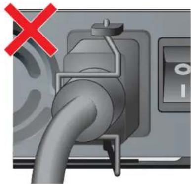
natural_image
Close-up of a gas pump plug with a red X mark indicating cancellation or failure (no text or symbols present)This device complies with Part 15 of the FCC Rules. Operation is subject to the following two conditions: (1) this device may not cause harmful interference, and (2) this device must accept any interference received, including interference that may cause undesired operation.
This Class A digital apparatus complies with Canadian ICES-003.

natural_image
Diagram of a multi-chamber electronic device with indicator lights and ports (no text or symbols)This device complies with Part 15 of the FCC Rules. Operation is subject to the following two conditions: (1) this device may not cause harmful interference, and (2) this device must accept any interference received, including interference that may cause undesired operation.
This Class A digital apparatus complies with Canadian ICES-003.

natural_image
Diagram of a multi-chamber electronic device with indicator lights and ports (no text or symbols)
natural_image
Diagram of a multi-chamber electronic device with indicator lights and ports (no text or symbols)natural_image
Close-up of a mechanical pipe connecting a valve, with a green checkmark overlay (no text or symbols)
natural_image
Close-up of a fuel pump plug with a red X mark indicating cancellation or failure (no text or symbols on the diagram itself)- 將電源線插到合適的電氣插座。
This device complies with Part 15 of the FCC Rules. Operation is subject to the following two conditions: (1) this device may not cause harmful interference, and (2) this device must accept any interference received, including interference that may cause undesired operation.
This Class A digital apparatus complies with Canadian ICES-003.

natural_image
Pure electrical circuit lines without any symbolsnatural_image
Close-up of a mechanical component with a green checkmark indicating approval (no text or symbols present)
natural_image
Close-up of a gas pump plug with a red X mark indicating cancellation or failure (no text or symbols present)This device complies with Part 15 of the FCC Rules. Operation is subject to the following two conditions: (1) this device may not cause harmful interference, and (2) this device must accept any interference received, including interference that may cause undesired operation.
This Class A digital apparatus complies with Canadian ICES-003.

© 2011 Aruba Networks, Inc. AirWave Aruba Networks®, Aruba Mobility Management System®
Dell PowerConnect W-AP
בְרַעָה אִיַתְאָה
:
הכלהה,הכלהה
| הכלההעַרְהָה אַרְהָה אַרְהָה אַרְהָה אַרְהָה אַרְהָה אַרְהָה אַרְהָה אַרְהָה אַרְהָה אַרְהָה |
| # send |
| # send "send" # send "send" # send "send" # send "send" # send "send" # send "send" # send "send" # send "send" # send "send" # send "send" # send "send" # send "send" # send "send" # send "send" # send "send" # send "send" # send "send" # send "send" # send "send" # send "send" # send "send" |
| # send "send" # send "send" # send "send" # send "send" # send "send" # send "send" # send "send" # send "send" # send "send" # send "send" # send "send" # send "send" # send "send" # send "send" # send "send" # send "send" # send "send" # send "send" # send "send" # |
| # send "send" # send "send" # send "send" # send "send" # send "send" # send "send" # send "send" # send "send" # send "send" # send "send" # send "send" # send "send" # send "send" # send "send" # send "send" # send "send" # send "send" # send "send" # send "send" # Send |
| # Send |
| # Send |
| # Send |
.הכלההוּרָהוּרָהוּרָהוּרָהוּרָהוּרָהוּרָהוּרָהוּרָהוּרָהוּרָהוּרָהוּרָהוּרָהוּרָה
.שְׁרָהִיַתְאָהִיַתְאָהִיַתְאָהִיַתְאָהִיַתְאָהִיַתְאָהִיַתְאָהִיַתְאָהִיַתְאָה
natural_image
Electrical panel with multiple switches and indicator lights (no visible text or symbols)natural_image
Close-up of a plug inserted into a device with a green checkmark indicating a status (no text or symbols on the plug itself)אַלְרָה: ozt cío, ucl
natural_image
Close-up of a mechanical pipe with a red 'X' mark indicating cancellation or failure, no text or symbols present.8.
This device complies with Part 15 of the FCC Rules. Operation is subject to the following two conditions: (1) this device may not cause harmful interference, and (2) this device must accept any interference received, including interference that may cause undesired operation.
This Class A digital apparatus complies with Canadian ICES-003. Cet appareil numérique de la classe A est conforme à la norme NMB-003 du Canada. Apparatet må tilkoples jordet stikkontakt. Laite on liitettävä suojamaadoituskoskettimilla varustettuun pistorasiaan.
הכלה,הכלה,הכלה,Class A is not in any state.

.EN55024 -1 EN55022 Class A כרִיְבָרִיְבָרִיְבָרִיְבָרִיְבָרִיְבָרִיְבָרִיְבָרִיְבָרִיְבָרִי
תְקּוֹת
- Dell PowerConnect W-6000 controller
- Copyright
- Open Source Code
- Legal Notice
- Preface....5
- Chapter 1 System Overview....7
- Chapter 2 Installing the Chassis....9
- Chapter 3 Verifying the Installation....15
- Chapter 4 The Fan Tray....17
- Chapter 5 Dell PowerConnect W-6000M3....21
- Chapter 6 The W-6000 Power Supply Module 23
- Chapter 7
- Specifications 29
- Overview of this Manual
- Related Documents
- Text Conventions
- Contacting Support
- Features
- Physical Description
- Pre-Installation Checklist
- Precautions
- Requirements
- Minimum Configuration
- Rack Mounting Kit
- Selecting a Location
- Rack Mounting the Chassis
- Adding W-6000M3 Controller Modules
- Connecting Power
- Built-in Redundancy
- Hot Swap
- Replacing a Fan Tray
- Prepare the New Fan Tray
- Remove the Old Fan Tray
- Insert the New Fan Tray
- Rating
- Load Sharing
- Redundancy
- Power Management
- W-6000M3 Module and PSU Configuration Table
- Inserting a Power Supply
- Removing a Power Supply
- Physical
- Environmental
- Operational
- Compliance
- Electromagnetic Interference
- United States
- FCC Class A
- Canada
- Safety
- Lithium Battery Notice
- Laser Notice
- Textkonventionen
- בְרַעָה אִיַתְאָה
Brand : DELL
Model : W6000
Category : Network Equipment