SHT 5000 - Alarm system Schabus - Free user manual and instructions
Find the device manual for free SHT 5000 Schabus in PDF.
User questions about SHT 5000 Schabus
0 question about this device. Answer the ones you know or ask your own.
Ask a new question about this device
Download the instructions for your Alarm system in PDF format for free! Find your manual SHT 5000 - Schabus and take your electronic device back in hand. On this page are published all the documents necessary for the use of your device. SHT 5000 by Schabus.
USER MANUAL SHT 5000 Schabus
Operating instructions
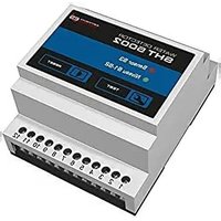
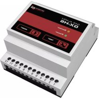
Water detector SHT 5000 - Item no.: 300744

In order to be able to constantly guarantee the product's optimum functionality and readiness for operation as well as your safety, we have a request: Please thoroughly read this operating instruction prior to the first use and observe all safety instructions! The operating instruction is a component of this product. Keep this, so you can always refer to it.
1. DELIVERY SCOPE
1 control device ▶
1 operating manual ▶
assembly material ▶
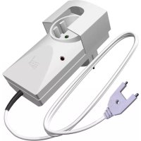
optional: water sensor (Item no.: 300745) ▶
2. SAFETY INSTRUCTIONS
2.1 General
Before you start mounting the device please read the operating instructions carefully.
The installation shall be performed by qualified personnel.
Packaging material is not a children's toy. Keep it away from children!
2.2 Ambient conditions
The standards used to assess the product specify limit values for use in the living area, business area and in small enterprises; the product has been intended for use in the following operating environments:
Residential buildings/living areas such as houses, flats, rooms, etc. selling areas such as • shops, wholesale markets, etc.
Premises of small enterprises such as workshops, service centers, etc.
All areas of application characterize themselves by a connection to the public low voltage • mains.
2.3 Batteries
Non-rechargeable batteries shall never be charged. Risk of explosion!
- Spent batteries shall immediately be removed from the transmitter! Increased risk of leakage!
Batteries must not be disposed of in domestic waste. Every consumer is legally obliged to properly dispose of batteries at the intended collection sites.
3. APPROPRIATE USE
The SHT 5000 water detector is a device for recognizing changes in water conditions. As soon as the sensor has contact with water, an acoustic and an optic alarm signal sounds and warns you against unexpected water ingress.
4. PRODUCT DESCRIPTION
Up to four water sensors or float switches can be connected to the device. As soon as one of the four sensors has contact with water, an acoustic alarm signal sounds and the activated loop can be identified by four LEDs. At the same time, a potential-free relay is switched on. That enables the connection to a BUS system (EIB), or to external devices:
Signal light (Item no.: 200894) ▶
Alarm horn (Item no.: 200982) ▶
Telephone dialer (Item no.: 200893) ▶
Magnetic cut-off valve 3/8 inch (Item no.: 200995)
Magnetic cut-off valve 1/2 inch (Item no.: 200996)
Two differing output messages can be defined for each sensor input:
▶ Alarm message with storage function: The alarm stays on and the relay is switched on, until the message is turned off again by pushing a button.
▶ Alarm message without storage function: The alarm remains and the relay is switched on, until the sensor no longer reports water. (For application as a level indicator or pump control).
In addition, for every sensor input, the acoustic alarm can be turned on and off.
Further, the device can be equipped with a 9 V block battery, and can also set off a warning – even in case of a power failure.
Additional equipment: Relay plug-in card (Item no.: 300747):
There are four potential-free relays on the plug-in card, and thus there are four independent control circuits available. For every sensor input a relay is assigned.
5. TECHNICAL SPECIFICATIONS
Operating voltage: 230 V AC / 50-60 Hz
Power consumption: approx. 4 W
Sensor connection: up to 4 water sensors
Cable length of sensor: up to 50 m (max)
Relay contact: 8 A / 230 V (potential-free two-way contact)
Acoustic pressure sounder: 90 dB @10 cm
Operating temperature: -15^ / +40^
Protection type: IP 20
Dimensions (HxWxD): 80x160x55 mm
Battery (optional): 9 V battery
6. INSTALLATION INSTRUCTIONS AND CONFIGURATION

The installation shall be performed by qualified personnel. Please note the five safety rules!
6.1 Wall installation
For installation on the wall, the four housing screws must be removed from the cover. Afterwards, the front plate must be lifted - if necessary - the ribbon cable must be removed from the electrical outlet. The subshell of the device can now be installed on the wall (assembly material is included).
6.2 Sensor installation
The sensor reacts to water contact at the two metal contacts (the sensor circuit is closed). The assembly height of the sensor defines, at what level the water detector will sound an alarm. The sensor cable can be lengthened up to a 50-meter dual-wire cable, and five water sensors can be connected per input in parallel.
6.3 Connection configuration

Important! The cables running to the water detector must be surface-mounted and installed in a fixed, solid maner!
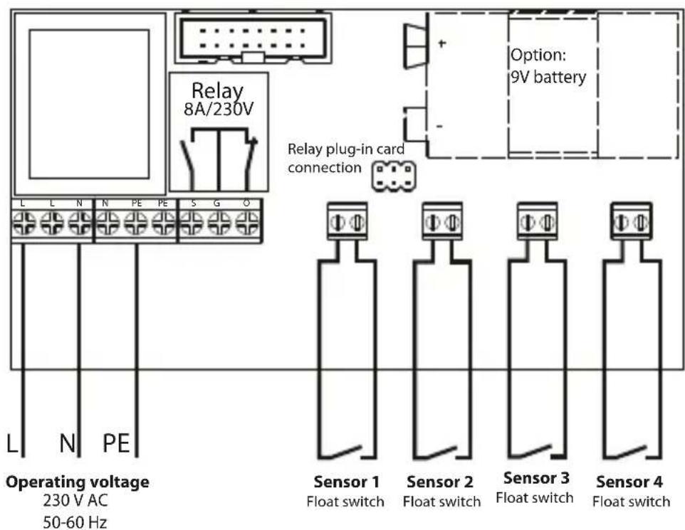
text_image
Relay 8A/230V Option: 9V battery Relay plug-in card connection L L N N PE PE S G O Operating voltage 230 V AC 50-60 Hz Sensor 1 Float switch Sensor 2 Float switch Sensor 3 Float switch Sensor 4 Float switch6.4 Settings of the miniature switch
At the delivered condition of the product, the miniature switch is set, as depicted in the picture on the right.
Switch1: ON = Battery monitoring is shut off
Switch2: ON = Storage function for Sensor 1 is switched on
Switch3: ON = Storage function for Sensor 2 is switched on
Switch4: ON = Storage function for Sensor 3 is switched on
Switch5: ON = Storage function for Sensor 4 is switched on
Switch6: ON = Buzzer is for all channels active
Switch7: ON = Buzzer for Channel 1 is active
Switch8: ON = Buzzer for Channel 2 is active
Switch9: ON = Buzzer for Channel 3 is active
Switch10: ON = Buzzer for Channel 4 is active
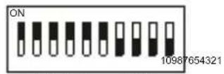
Miniature switch
text_image
Buzzer6.5 Relay connection configuration
When connecting additional devices to the potential-free relay, please note that the switching capacity may not be exceeded.
Relay status in monitoring mode:

The relay is „energized“ (make contact closed/break contact open)
Relay status in alarm mode:

The relay „decreases“ (make contact open/ break contact closed)
Wiring example: Magnetic cut-off valve
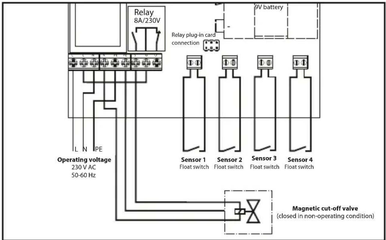
text_image
Relay 8A/230V 9V battery Relay plug-in card connection Operating voltage 230 V AC 50-60 Hz IL N IPE Sensor 1 Float switch Sensor 2 Float switch Sensor 3 Float switch Sensor 4 Float switch Magnetic cut-off valve (closed in non-operating condition)After the water detector and the sensors have been set up, a functional test must be carried out. By pushing the
Function test of the sensor: touch both sensor contacts with a waterlogged cloth or an electric conductive metal and the alarm is set off immediately.

For your own safety, we recommend that you carry out this test constantly!
7.2 Operation of the water detector with mains supply (without battery)
LED POWER is green: The water detector is connected to the mains supply and mains voltage.
LED SENSOR 1-4 light up: As soon as a sensor recognizes a rising water level, its LED will light up red. The alarm is set off and the potential-free relay (two-way contact) switches.
The acoustic alarm is deactivated by pressing the button
▶ Alarm message with storage function: The alarm stays and the relay is switched on, until the message is removed by pushing the
▶ Alarm message without storage function: The alarm remains and the relay is switched on, until the sensor no longer reports water.
7.3 Operation of the water warning device with power supply (with bat.)
LED POWER is green: The water detector is connected to the power source and network voltage.
LED BATTERY is blinking: No battery, or too little battery power. Insert a battery, or change the battery.
LED POWER goes out: Power failure! The water detector is operated in battery mode.
Through a function test, the device can also be monitored in battery mode: All alarm LEDs for sensors 1 - 4 must be red, and an acoustic alarm sounds.
8. GENERAL
Elektrotechnik Schabus GmbH & Co. KG is not liable for damages and/or losses of any kind such as individual damages or consequential damages brought about by the water detector not issuing an alarm despite any changes in water conditions.
8.1 Cleaning and care
Avoid the effects of moisture (spray or rain water), dust as well as direct insolation on the device. Clean the device exclusively with a dry linen cloth; in case of heavy dirt accumulation, it may be slightly moistened. Do not use any detergents containing solvents.
8.2 Declaration of conformity
The declaration of conformity can be obtained from our website: www.elektrotechnik-schabus.de
8.3 Warranty
We grant an implied warranty on material and quality defects of your electronic product by Elektrotechnik Schabus from the date of purchase. Elektrotechnik Schabus will repair or replace your device free of charge on the following conditions:
In case of implied warranty, the device has to be returned with the following documents: error description, proof of purchase as well as your address and delivery address (name, phone number, street, house number, postcode, city, country).
Devices returned to Elektrotechnik Schabus shall be sufficiently packaged. Elektrotechnik • Schabus will not take liability for any damage or loss during shipment.
- The device has to have been used in accordance with the operating instructions. Elektrotechnik Schabus will not take liability for any damage resulting from accident, abuse, modifications or carelessness.
Elektrotechnik Schabus will not take liability for any loss, damage or costs resulting from the use of the devices or the accessory equipment.
The warranty does not affect your statutory rights as consumer.
8.4 Return shipment
Should your device be defective, we offer you the following option:
Contact Elektrotechnik Schabus by
Phone +49 (0) 80 36 / 67 49 79 - 0
Fax +49 (0) 80 36 / 67 49 79 - 79
Email info@elektrotechnik-schabus.de
8.5 Environmental Information (WEEE-NO: 91394868)
For the production of the purchased product, natural raw materials had to be obtained and used. It may contain substances hazardous to health and the environment.
In order to avoid the distribution of these substances in your environment and save natural resources, we ask you to use the appropriate take-back systems. Thanks to these systems, the materials of your product can be recycled in an environmentally friendly way, after its service life has expired. The strike-through wastepaper basket symbol reminds you of the use of these systems. Should you wish to obtain more information on collection, reuse and recycling systems, please refer to the waste advisory service in your city. You may also refer to us to obtain more information on the environmental compatibility of our products.
MERCI DE VOTRE CONFIANCE!
3. WERKINGSBESCHRIJVING
3. USO CONFORME ALLO SCOPO
natural_image
Black industrial electrical connector block with four ports and terminal connectors (no visible text or symbols)Relay plug-in card (Item no. 300747)
natural_image
Close-up of a metallic connector with a cylindrical body and hexagonal end caps (no text or symbols visible)natural_image
White conical device with a metallic base and two side handles, no visible text or symbols.Alarm horn (Item no. 200982)
natural_image
Front view of a white electronic device with a digital keypad and control buttons (no visible text or symbols)natural_image
Close-up of a black cylindrical object with a tapered top and side grooves, resembling a warning or sensor device (no text or symbols visible)Signal light (Item no. 200894)
natural_image
Close-up of a black mechanical component with mounting holes and a labeled part '3/8 Zoll (inch)' below (no other text or symbols)Magnetic cut-off valve (Item no. 200995)