
GX-A1+ - Alarm system Schabus - Free user manual and instructions
Find the device manual for free GX-A1+ Schabus in PDF.


| Product Type | Wireless Alarm System |
| Brand | Schabus |
| Model | GX-A1+ |
| Dimensions (Control Panel) | 120 x 80 x 25 mm |
| Weight (Control Panel) | 180 g |
| Power Supply | DC 12V / 1A adapter |
| Backup Battery | Lithium-ion 3.7V 500 mAh |
| Number of Zones | 8 wireless zones |
| Wireless Range | Up to 100 m in open space |
| Compatible Sensors | Door/window contact, motion detector, smoke detector |
| Alarm Sound Level | 110 dB |
| Main Functions | Arm/disarm, panic button, remote control, smartphone alerts (via app) |
| Keypad | Touch keypad with backlight |
| Communication | Wi-Fi, GSM (optional) |
| Maintenance | Clean with dry cloth; replace batteries annually |
| Safety Certifications | CE, FCC |
| Operating Temperature | -10°C to 45°C |
| Storage Temperature | -20°C to 60°C |
| Spare Parts Available | Remote controls, sensors, power adapter |
| Repairability | Replaceable batteries and fuses; professional service for board repair |
| General Information | Designed for residential and small business security |
Frequently Asked Questions - GX-A1+ Schabus
User questions about GX-A1+ Schabus
0 question about this device. Answer the ones you know or ask your own.
Ask a new question about this device
Download the instructions for your Alarm system in PDF format for free! Find your manual GX-A1+ - Schabus and take your electronic device back in hand. On this page are published all the documents necessary for the use of your device. GX-A1+ by Schabus.
USER MANUAL GX-A1+ Schabus
Operating instructions
GAS ALARM GX-A1+ Item no.: 300892

HERZLICHEN DANK FÜR IHR VERTRAUEN!
In order to be able to constantly guarantee the product's optimum functionality and readiness for operation as well as your safety, we have a request: Please thoroughly read this operating instruction prior to the first use and observe all safety instructions! The operating instruction is a component of this product. Keep this, so you can always refer to it.
1. DELIVERY SCOPE
▶ 1 control device GX-A1+ without sensor
▶ 1 operating manual
▶ 1 Assembly material (4 screws, wall plugs)
Accessories (not included in delivery)
▶ gas sensor, must be ordered separately according to the type of gas
▶ warning lamp
▶ telephone dialer
▶ cut-off valve
▶ alarm horn
2. SAFETY INSTRUCTIONS
2.1 General
• Before you start mounting the device please read the operating instructions carefully.
• The installation shall be performed by qualified personnel.
- Packaging material is not a children's toy. Keep it away from children!
2.2 Ambient conditions
The standards used to assess the product specify limit values for use in the living area, business area and in small enterprises; the product has been intended for use in the following operating environments:
- Residential buildings/living areas such as houses, flats, rooms, etc. selling areas such as shops, wholesale markets, etc.
- Premises of small enterprises such as workshops, service centers, etc.
- All areas of application characterize themselves by a connection to the public low voltage mains.
3. APPROPRIATE USE
The GAS ALARM GX-A1+ is a gas warning device for various gases and can already deliver a warning at a gas concentration that lies below life-threatening values. This monitoring system is, therefore, in line with its purpose, set to a very high sensitivity. For each type of gas, a suitable sensor must be used (for information on trigger levels and minimum concentration, see the instructions for the sensor).
An LCD display keeps you continually informed of the current gas concentration. The alarm is signalled acoustically and optically. At the same time, a potential-free relay contact is closed, which can be used, for example, to cut off the gas line by means of a magnetic cut-off valve so that no further gas can escape from any leakage of the gas line or gas furnace. The device may not be used in areas with a risk of explosion. Another use of the device as described above is not authorized.
4. INSTALLATION INSTRUCTIONS

The assembly must be carried out by a qualified specialist. Please note the five safety rules!

The GAS ALARM GX-A1+ and the sensor may only be installed in dry interiors of residential buildings and rooms with similar uses and must be correctly positioned depending on the gas type so that the warning device functions properly.
4.1 Wall mounting GX-A1+
For wall mounting, the four housing screws at the corners of the front panel must be loosened. Then the front panel is removed and, if necessary, the ribbon cable is pulled off the connector. The lower shell of the housing can now be mounted on a wall (mounting material is included).

Important! The connection cables that lead to the gas detector must be permanently installed as surface-mounted cables.
4.2 Sensor mounting
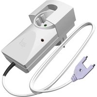
Depending on the type of sensor connected, the device detects various gases, e.g. town and natural gas (methane / butane), coolants and refrigerants or CO2. A prescribed mounting height is necessary for each sensor type, as gases have different properties.
For carbon monoxide there are specialized gas warning systems, e.g. the GX-C300 series.

It is essential to pay attention to the prescribed mounting height!
Please read the instructions for use of the sensor you want to use and find out the specified mounting height from it!
Available and compatible sensors (07/2021)
GX-SE 200897 Town / natural gas (methane, butane, propane, ethanol, ...)
GX-CFC 200901 Coolant / refrigerant (R22, R32, R404a, R410a, R1234yf, ...)
GX-DS 200884 Carbon dioxide from used air (2500 ppm)
GX-CO2-25 200989 CO2 from used air (2500 ppm with its own alarm)
GX-CO2-30 300315 CO2 from techn. systems under pressure (3% vol., own alarm)
4.3 Pin assignment sensor
Note the color coding of the sensor cable (see also 4.5 Connection diagram).
brown 5 volts operating voltage connection terminal 1 (left)
white sensor voltage connection terminal 2 (middle)
green gnd / 0 volt / ground connection terminal 3 (right)
4.4 Terminal assignment relay
When connecting accessory devices to the potential-free relay, make sure that the max. switching current of 5 amperes is not exceeded.
▶ Relay status in monitoring mode:
The relay is "picked up" (normally open contact closed / normally closed contact open)
▶ Relay status in alarm or error mode:
The relay "drops out" (NO contact open / NC contact closed)
Limit data: Re1 (alarm) 250 V \~ / 5 A Re2 (error) 60 V = / 5 A
Application • Shutdown of the gas boiler • building management system
example • Solenoid shut-off valve • Telephone dialer
- Signal horn / warning light - Bus connection modules
connections: G (com) common / Ö (n.c.) normally closed / S (n.o.) normally open
4.5 Connection diagram
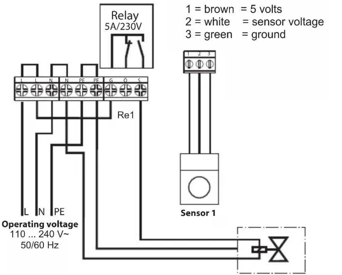
Magnetic cut-off valve (closed in non-operating condition)
5. COMMISSIONING / FUNCTIONAL TEST
An electrical function test is carried out when the mains voltage is applied, then the heating-up phase is started for approx. 3 minutes, the display shows System: OK and Sensor: Preheat until the sensor has reached the required operating temperature, then Sensor: Ready
Please note: Even in the event of a power failure, the test and the heating-up phase are restarted.
5.1 This is how the warning system works
The GX-A1+ evaluates voltages supplied by the sensor. In passive sensors, such as the GX-SE, the gas-sensitive tin oxide is located in a voltage divider, which changes its partial voltage according to the detected gas concentration. With active sensors such as the GX-CO2-30, this voltage is generated by a µ Controller.
The following voltage ranges are interpreted and displayed by the GX-A1+ :
| Display: top line | bottom line | ||
| 0,0 ... 0,1V | System: Error | Sensor: Broken | Cable break or total sensor failure |
| 0,1 ... 0,3V | System: Error | Sensor: Fault | Sensor error, voltage too low |
| 0,3 ... 2,0V | System: OK | Sensor: Ready | Monitoring mode, idle |
| 2,0 ... 2,5V | PreAlarm !!! | Sensor: 2123m* | Pre-alarm, sensor voltage in mV |
| 2,5 ... 5,0V | Alarm !!! | Sensor: 2789m* | Main alarm, sensor voltage in mV*) Exemplary values |
And this is how the two relays switch depending on the sensor voltage, with reference to the normally open contact between connections G and S:
| Re1 (Alarm) | Re2 (Error) | ||
| 0,0 ... 0,1V | open | open | Re drop off after 10 s. ▶5.3 (page14) |
| 0,1 ... 0,3V | closed | open | Re2 drop off after some seconds |
| 0,3 ... 2,0V | closed | closed | Relays pick up during commissioning |
| 2,0 ... 2,5V | closed | closed | Relays remain energized |
| 2,5 ... 5,0V | open | closed | Re1 drop off after about 10 seconds |
In order to prevent the relays from fluttering in the limit range, switch always take a time delay of around 10 seconds into account.
This is how the display of the three status LEDs and the acoustic alarm of the built-in piezo sounder are dependent on the sensor voltage:
| OPERATE green | ERROR yellow | ALARM red | acoustic alarm | |
| 0,0 ... 0,1V | lights up | flashes | off | one beep every 30 seconds |
| 0,1 ... 0,3V | lights up | flashes | off | a double beep every 10 seconds |
| 0,3 ... 2,0V | lights up | off | off | no sounds |
| 2,0 ... 2,5V | lights up | off | off | one beep every 10 seconds |
| 2,5 ... 5,0V | lights up | off | flashes | interrupted continuous alarm tone |
5.2 The RESET / TEST button
5.2.1 The test function
The GX-A1+ has a test function for its internal systems. The connected sensor is not also tested. To test the sensor, please refer to its operating instructions to find out what is recommended for the respective type.
To protect your ears from the loud alarm sound, place the heel of your right hand on the sound opening of the piezo alarm device and press and hold the RESET / TEST button with your left index finger. After a few seconds each, the following will happen one after the other:
- The alarm tone sounds continuously, the green and yellow LEDs light up, the red LED and the display backlight flashes
- Relay Re2 „Fault“ drops out
- Relay Re1 „Alarm“ drops out
- After releasing the RESET / TEST button, the Re2 „Fault“ relay pulls immediately on again, LEDs, display and alarm device are back to normal
- Relay Re1 „Alarm“ picks up again
So you can be sure that all acoustic and visual alarms are reliable and that the switching of the relays and their delays work properly. If the test is activated during the „pre-alarm“ phase, no alarm tone can be heard.
5.2.2 The reset function for the acoustic alarm
During the „Alarm“ phase, pressing the RESET / TEST button for 2 seconds has the function of an acoustic alarm reset, only the acoustic alarm is silenced, the alarm relay remains de-energized and the visual warning is retained. For the time the button is pressed during the “alarm” phase, the Re2 “fault” relay drops out briefly in order to inform the building management system (and possibly its recording) of the acknowledgment.
5.3 The SERVICE button
In monitoring mode, use the SERVICE button to scroll through the 15 different display pages to obtain additional information / statistics on your warning system. A longer (not harder) press on the SERVICE button switches back to the main display page. Some meters will often already have a number, because we test your device before delivery. The following information can be called up:
top line bottom line, sample values
| System: OK Sensor: Ready Main screen | ||
| Product Type GX-A1 Series of the warning system | ||
| Software Version X0.05 Software Version | ||
| On Time 15h 2468sec Total on-time in hours, seconds | ||
| Last Error Code 3 last error code, 3 = omission of 230V | ||
| Sensor Voltage | 767 mV currently measured sensor voltage | |
| Voltage at Alarm | 0 mV | No function in this Software version |
| Error Counter | 22 | total errors counted |
| Starts Counter | 15 | times, system switched on |
| System Temp | 36 °C | Operating temperature in the housing |
top line bottom line
| Chip Temp | 46 °C | Temperature in the processor |
| Last Error @ 14 h | time for no more system mistakes | |
| Max Chip Temp | 48 °C | max. Temperature in the processor |
| Max System Temp | 38°C | max. Temperature in the housing |
| Alarm Count ext | 24 | total alarms counted |
| System: OK | Sensor: Ready | back to mainscreen |
▶ Pro tip: Sensors have a limited shelf life. With it, for example, a heater can continue to run without a sensor, press the SERVICE and the TEST / RESET button simul-
taneously for at least 5 seconds. Relay Re2 remains de-energized, the alarm tone can still be heard every 30 seconds, but relay Re1 „Alarm“ picks up again so that a device connected to it can continue to operate for 48 hours. The time counts down in the second line of the display and looks like this : Broken48
6. TECHNISCHE DATEN
Operating voltage : 110 ... 240 V\~ / 50-60 Hz
Power consumption: 2 ... 10 VA, depending on the operating status
Relay contacts: 2x potential-free changeover contacts n.o. / n.c.
Relais Re1 „Alarm“: 250 V\~ / 5 A / secured
Relais Re2 „Error“: 60 V= / 5 A / secured
Sensor connections: max. 1 sensor possible
Sensor Operating voltage: 5 V= / max. 300 mA
Analysis: voltage / ADC
Sound pressure piezo alarm device: 85dB(A)@1m
2x 16 characters display : white on blue, backlit, flashes in the event of an alarm, text in English
3 LEDs: green operate, yellow error, red alarm
Temperature range: -10°C... +50°C
humidity: 10%rH ... 90%rH, not condensing
Protection class: IP20 (IP65 possible with surcharge)
Connection type: Screw terminals (all connections)
mounting: Wall mounting (4 screws, dowels included)
Permanent installation: Fixed lines as surface-mounted, feed from below, thread prepared for PG screw connections
Dimensions (H x B x D): 80 x 160 x 55 mm
item no. / EAN (GTIN) 300892 / 4044764004566
7. GENERAL
Elektrotechnik Schabus GmbH & Co. KG is not liable for damages and/or losses of any kind such as individual damages or consequential damages brought about by the gas detector not issuing an alarm despite the presence of an elevated gas concentration.
To ensure that the sensor is always in a proper functioning state, you should replace it after 5 years for safety's sake.
7.1 Cleaning and care
Avoid the effects of moisture (spray or rain water), dust as well as direct insolation on the device. Clean the device exclusively with a dry linen cloth; in case of heavy dirt accumulation, it may be slightly moistened. Do not use any detergents containing solvents.
7.2 Declaration of conformity
The CE mark on the device confirms that it conforms to relevant EU directives. The declaration of conformity is available for viewing at the address below.
All rights, technical changes, errors and misprints are reserved.
7.3 Warranty
We grant an implied warranty on material and quality defects of your electronic product by Elektrotechnik Schabus from the date of purchase. Elektrotechnik Schabus will repair or replace your device free of charge on the following conditions:
- In case of implied warranty, the device has to be returned with the following documents: error description, proof of purchase as well as your address and delivery address (name, phone number, street, house number, postcode, city, country).
- Devices returned to Elektrotechnik Schabus shall be sufficiently packaged. Elektrotechnik Schabus will not take liability for any damage or loss during shipment.
- The device has to have been used in accordance with the operating instructions. Elektrotechnik Schabus will not take liability for any damage resulting from accident, abuse, modifications or carelessness.
- Elektrotechnik Schabus will not take liability for any loss, damage or costs resulting from the use of the devices or the accessory equipment.
• The warranty does not affect your statutory rights as consumer.
7.4 Return shipment
Should your device be defective, we offer you the following option:
Contact Elektrotechnik Schabus by
Phone +49 (0) 80 36 / 67 49 79 - 0
Fax +49 (0) 80 36 / 67 49 79 - 79
Email info@elektrotechnik-schabus.de
7.5 Environmental information
For the production of the purchased product, natural raw materials had to be obtained and used. It may contain substances hazardous to health and the environment. In order to avoid the distribution of these substances in your environment and save natural resources, we ask you to use the appropriate take-back systems. Thanks to these systems, the materials of your product can be recycled in an environmentally friendly way, after its service life has expired. (WEEE-NO: 91394868)
The strike-through wastepaper basket symbol reminds you of the use of these systems.

Should you wish to obtain more information on collection, reuse and recycling systems, please refer to the waste advisory service in your city. You may also refer to us to obtain more information on the environmental compatibility of our products.


- OPERATING INSTRUCTIONS
- HERZLICHEN DANK FÜR IHR VERTRAUEN
- DELIVERY SCOPE
- ACCESSORIES (NOT INCLUDED IN DELIVERY)
- SAFETY INSTRUCTIONS
- 2.1 GENERAL
- 2.2 AMBIENT CONDITIONS
- APPROPRIATE USE
- INSTALLATION INSTRUCTIONS
- 4.1 WALL MOUNTING GX-A1
- 4.2 SENSOR MOUNTING
- AVAILABLE AND COMPATIBLE SENSORS (07/2021)
- 4.3 PIN ASSIGNMENT SENSOR
- 4.4 TERMINAL ASSIGNMENT RELAY
- COMMISSIONING / FUNCTIONAL TEST
- 5.1 THIS IS HOW THE WARNING SYSTEM WORKS
- 5.2 THE RESET / TEST BUTTON
- 5.2.1 THE TEST FUNCTION
- 5.2.2 THE RESET FUNCTION FOR THE ACOUSTIC ALARM
- 5.3 THE SERVICE BUTTON
- TECHNISCHE DATEN
- GENERAL
- 7.1 CLEANING AND CARE
- 7.2 DECLARATION OF CONFORMITY
- 7.3 WARRANTY
- 7.4 RETURN SHIPMENT
- 7.5 ENVIRONMENTAL INFORMATION
Brand : Schabus
Model : GX-A1+
Category : Alarm system