ClimaData Stick - Multimeter Laserliner - Free user manual and instructions
Find the device manual for free ClimaData Stick Laserliner in PDF.

| Product Type | Temperature and humidity data logger multimeter |
| Brand | Laserliner |
| Model | ClimaData Stick |
| Dimensions (L x W x H) | 101 x 25 x 23 mm |
| Weight | 42 g (with battery and wall mount) |
| Power supply | 1 lithium battery 3.6 V type 1/2 AA (14250) |
| Battery life | Approximately 1 year |
| Temperature measurement range | -40°C to 70°C |
| Temperature accuracy | ±1°C (-10°C to 40°C), ±2°C elsewhere |
| Humidity measurement range | 0% to 100% RH |
| Humidity accuracy | ±3% (40-60% RH), ±3.5% (20-40%, 60-80%), ±5% (0-20%, 80-100%) |
| Resolution | 0.1% RH, 0.1°C, 0.1°F |
| Memory capacity | 20,010 values |
| Measurement interval | 2 s to 24 h |
| Interface | USB |
| Software | Windows XP/Vista/7/8/10, 32/64 bit |
| Functions | Real-time and long-term measurement, alarm, recording |
| Display | LED (recording and alarm indication) |
| Included accessories | Protective cap, wall mount, software CD |
| Maintenance | Clean with a slightly damp cloth; avoid solvents and abrasive cleaners |
| Safety | Proper use, do not modify the device, avoid mechanical shocks and extreme temperatures |
| Operating conditions | -40°C to 70°C, without condensation, max. altitude 2000 m |
| Storage conditions | -40°C to 70°C, max. humidity 80% RH |
Frequently Asked Questions - ClimaData Stick Laserliner
User questions about ClimaData Stick Laserliner
0 question about this device. Answer the ones you know or ask your own.
Ask a new question about this device
Download the instructions for your Multimeter in PDF format for free! Find your manual ClimaData Stick - Laserliner and take your electronic device back in hand. On this page are published all the documents necessary for the use of your device. ClimaData Stick by Laserliner.
USER MANUAL ClimaData Stick Laserliner
natural_image
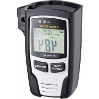
Exterior view of a Laserliner ClimaData Stick device (no text or symbols on body)
-40°C... 70°C
0%... 100% rH
FAST SENSOR
Laserliner
!
natural_image
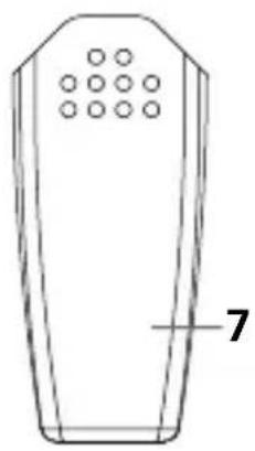
Line drawing of a rectangular device with circular indentations and a labeled number 7 (no text or symbols on the device itself)
natural_image
Technical line drawing of a mobile phone casing with two circular buttons and a labeled component (no text or symbols beyond the number 8)natural_image
Diagram of a USB connector showing internal components and pin layout (no text or symbols)Completely read through the operating instructions, the „Warranty and Additional Information“ booklet as well as the latest information under the internet link at the end of these instructions. Follow the instructions they contain. This document must be kept in a safe place and passed on together with the device.
Function / Application
This measuring device is used for long-term and real time measurement of ambient temperature and humidity. Measurements are stored internally and can be accessed by connecting the device to a PC via USB. Using the supplied software on a PC, the measurement parameters can be configured, a new measurement prepared, and the data subsequently analysed.
General safety instructions
- The device must only be used in accordance with its intended purpose and within the scope of the specifications.
– The structure of the device must not be modified in any way. - Do not expose the device to mechanical stress, extreme temperatures or significant vibration.
Safety instructions
Dealing with electromagnetic radiation
– The measuring device complies with electromagnetic compatibility regulations and limit values in accordance with EMC-Directive 2014/30/EU.
- Local operating restrictions – for example, in hospitals, aircraft, petrol stations or in the vicinity of people with pacemakers – may apply. Electronic devices can potentially cause hazards or interference or be subject to hazards or interference.
Information on maintenance and care
Clean all components with a damp cloth and do not use cleaning agents, scouring agents and solvents. Store the device in a clean and dry place.
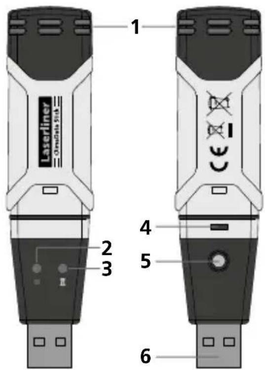
1 Sensor
2 Measurement active
natural_image
Line drawing of a rectangular device with circular indentations and a labeled number 7 (no text or symbols on the device itself)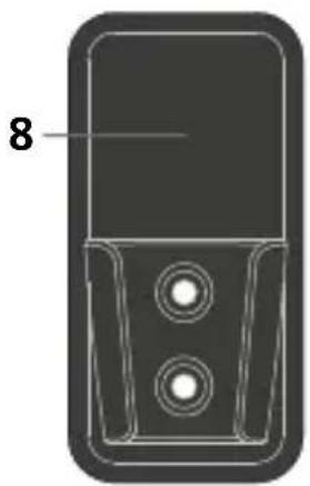
natural_image
Technical line drawing of a mobile phone casing with two circular buttons and a labeled component (no text or symbols beyond the number 8)3 Alarm function
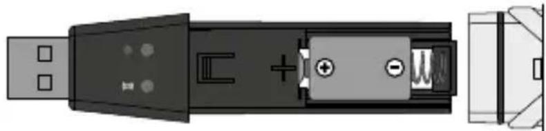
4 Battery compartment
5 Start measurement recording
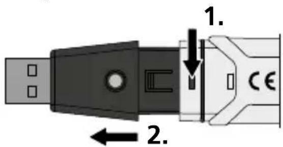
6 USB interface
7 Protective cap
8 Wall bracket
1 Inserting battery
Open the battery compartment and insert battery according to the symbols. Be sure to pay attention to polarity. With measurement recording activated, no LED flashing or LED (2) flashing red every 60 seconds indicates the battery charge is low.
natural_image
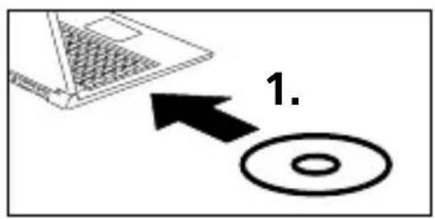
Diagram of a USB connector showing internal components and pin layout (no text or symbols)2 Software installation / Commissioning
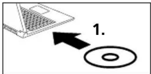
Load the CD in the drive and follow the installation routine. Close the installation program once installation has been successfully completed.
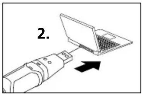
Now plug the device in a free USB port on your computer and start the application.
!
The software is only available in English.
3 User interface
![Clima-OS - [Datalogger] File (F) Help (H) Graph with markers](/content/2026/04/606282/images/421f3f68ca2488b21aa048ff892198761b4699f4c1599f924876372e88aea154.jpg)

Open
Open saved files

Save
Save the recorded data to the hard drive

Real time measurement
Starts real time measurement with the device connected

Download
Download the recorded data

Setup
Define measurement-specific settings

Help
4 Setup menu - long-term measurement
Measurement-specific settings on the connected device can be defined in the Setup menu.
!
New configuration automatically deletes all existing data.
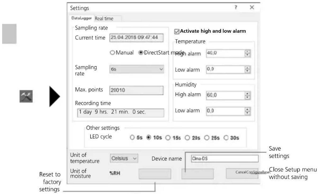
4.1 Current time
„Current time“ shows the date and time of your computer.
4.2 Start mode
Measurement can be started manually or directly.
Manual: Measurement is started by briefly pressing button (5).
LED (2) double-flashing indicates that measurement has not yet started.
Direct: Measurement starts after the settings have been saved.
LED (2) flashes green every 10 seconds.
4.3 Sampling rate
The sampling rate defines how often measurements are recorded. Setting options: 2 ... 30 seconds, 1 / 5 / 15 / 30 minutes and 1 / 5 / 12 / 24 hours.
„Max. points“ shows the maximum number of measurements. The maximum measurement duration is calculated under „Recording time“. The measurement memory is full at the end of this time.
4.4 LED cycle setting
LED (2) indicates that recording is active. The LED signal can be set to appear every 5, 10, 15, 20, 25 or 30 seconds.
The alarm range can be freely defined for the two measured variables temperature and relative humidity. If the measured value goes above or below the set cap or floor, the alarm LED (3) flashes every 10 seconds.
Temperature below set value: LED (3) flashes yellow
Temperature above set value: LED (3) double-flashes yellow
Humidity below set value: LED (3) flashes red
Humidity above set value: LED (3) double-flashes red
4.6 Unit of temperature
Measured values can be shown in °C or °F.
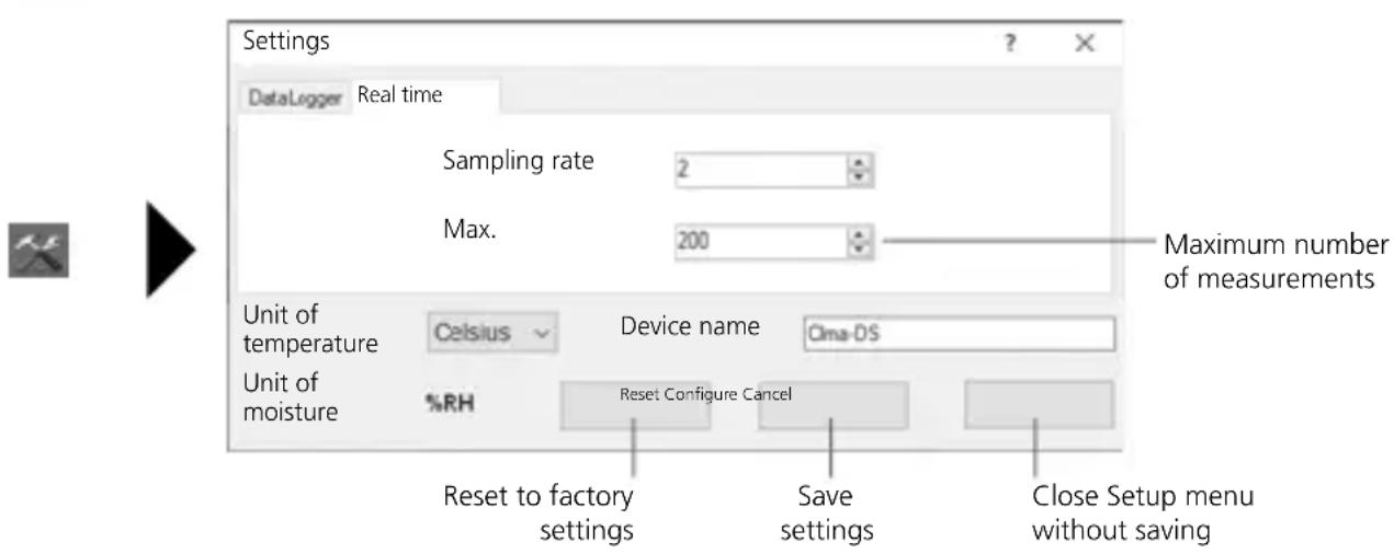
5 Setup menu - real time measurement
Measurement-specific settings on the connected device can be defined in the Setup menu.

New configuration automatically deletes all existing data.
6 Notes on the measurement process and on use
Long-term measurement
- Connect ClimaData Stick to the PC
- Download and backup any existing data. Starting or configuring a new measurement deletes all existing data.
- Configure recording in the Setup menu (see section 4) and save the settings
- Depending on your start parameter, position the device at the measuring point and record measurements. Briefly press button 5 for „manual start“.
- The end of recording is reached when the memory is full or the recording is stopped by connecting and reading out the device.
- Connect ClimaData Stick to the PC, download and backup data.
Real time measurement
- Connect ClimaData Stick to the PC
- Download and backup any existing data. Starting or configuring a new measurement deletes all existing data.
- Configure recording in the Setup menu (see section 5).
- Recording starts when the settings are saved.
- The data can be saved at the end of recording.

Position the device upright to ensure sufficient air circulation around the sensor. Use the supplied wall bracket.

If the device has been placed in a cold and/or very humid environment, condensation may form in the sensor housing when it is removed due to the change in climate. Position the device upright for a while to allow it to acclimatise.
7 Download


To edit and document the recorded data, they must be transferred to the software program. To do this, start the software and connect the device to the PC vis USB interface.

Long-term measurements are saved as a PDF file on the stick. Other data are not saved automatically.
8 Measurement analysis
The recorded measured values are shown in a list and on a bar graph.
Long-term measurement
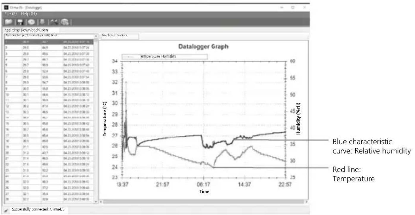
line
| Time | Temperature (°C) | Humidity (%/H) | |--------|------------------|----------------| | 13:37 | 26.8 | 32.0 | | 21:57 | 26.0 | 30.0 | | 06:17 | 24.0 | 28.0 | | 14:37 | 26.0 | 30.0 | | 22:57 | 26.5 | 31.0 |Real time measurement
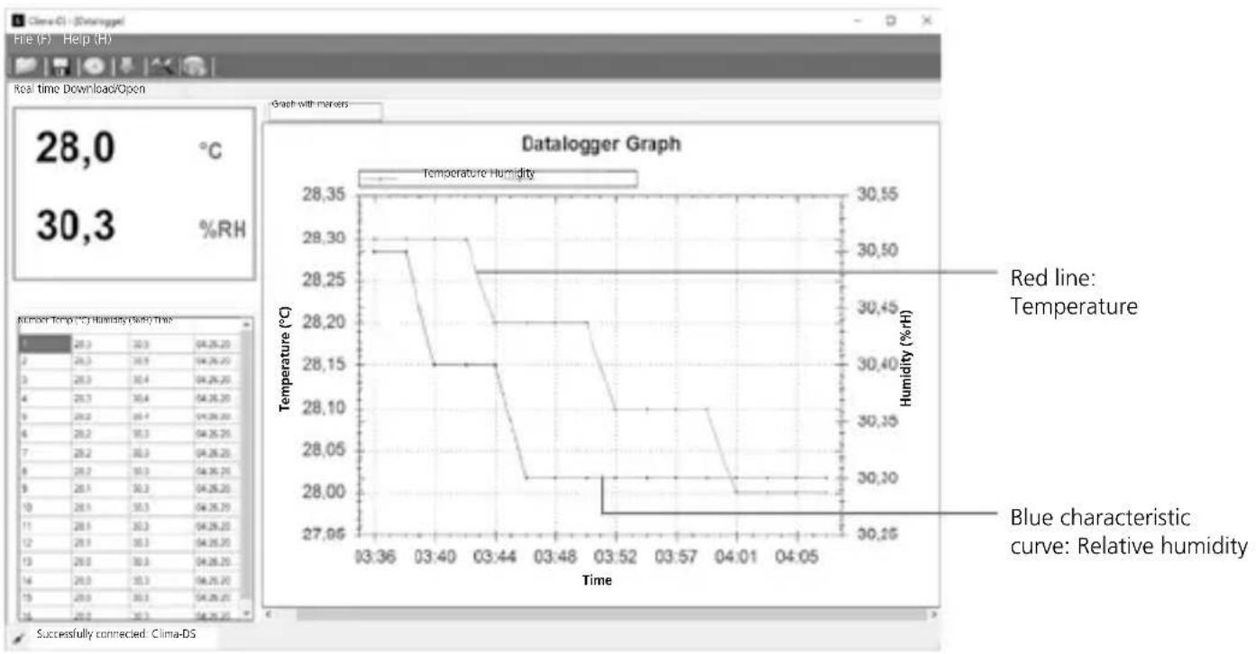
line
| Time | Temperature (°C) | Humidity (%H) | |--------|------------------|---------------| | 03:36 | 28.30 | 30.50 | | 03:40 | 28.15 | 30.40 | | 03:44 | 28.20 | 30.35 | | 03:48 | 28.05 | 30.30 | | 03:52 | 28.00 | 30.25 | | 03:57 | 28.05 | 30.30 | | 04:01 | 28.00 | 30.25 | | 04:05 | 28.00 | 30.25 |8.1 Zoom
You can zoom in and out of partial areas. Place the mouse pointer on the bar graph and scroll. Use the horizontal scroll bar to display further measurements.
8.2 Context menu
The bar graph can be copied, saved as an image, printed and zoomed in the context menu.
| Copy |
| Save image as... |
| Page setup... |
| Print... |
| Show point values |
| Unzoom (decrease) |
| Cancel all zoom / pan actions |
| Reset scaling |
Technical data
| Accuracy (absolute) | Ambient temperature | |
| -40°C ... 70°C | -40°F ... 158°F | |
| ±1°C (-10°C ... 40°C) | ±1,8°F (14°F ... 104°F) | |
| ±2°C (-40°C ... -10°C, +40°C ... 70°C) | ±3,6°F (-40°F ... -14°F, +104°F...158°F) | |
| Relative humidity | ||
| 0% ... 100% | ||
| ±3% (40% ... 60%) | ||
| ±3,5% (20% ... 40%, 60% ... 80%) | ||
| ±5% (0% ... 20%, 80% ... 100%) | ||
| Resolution | 0,1% rH, 0,1°C, 0,1°F | |
| Memory | 20010 individual measurements | |
| Measuring interval | 2s ... 24h | |
Technical data
| Operating conditions | -40°C ... 70°C (-31°F ... 158°F), non-condensing humidity, max. altitude 2000 m above sea level |
| Storage conditions | -40°C ... 70°C (-31°F ... 158°F), max. humidity 80% rH |
| Power supply 1x 3.6V | Lithium (type 1/2 AA, 14250) |
| Battery life | 1 year (typically, depends on measurement intervals, ambient temperature and the use of alarm LEDs) |
| Dimensions | 25 x 101 x 23 mm (W x L x H) |
| Weight | 42 g (including battery and wall bracket) |
| System requirements | Windows XP / Vista / 7 / 8 / 10, 32bit / 64bit |
Subject to technical alterations. 18W28
EU directives and disposal
This device complies with all necessary standards for the free movement of goods within the EU.
This product is an electric device and must be collected separately for disposal according to the European Directive on waste electrical and electronic equipment.
Further safety and supplementary notices at:
http://laserliner.com/info?an=clidasti
!
natural_image
Line drawing of a rectangular device with circular indentations and a labeled number 7 (no text or symbols on the device itself)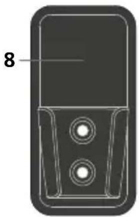
natural_image
Technical line drawing of a mobile phone casing with two circular buttons and a labeled component (no text or symbols beyond the number 8)natural_image
Diagram of a USB connector showing internal components and pin layout (no text or symbols)natural_image
Line drawing of a remote control device with no text or symbols
natural_image
Diagram of a mobile phone casing with two circular buttons and a labeled number 8 (no text or symbols beyond the label)natural_image
Diagram of a USB connector showing internal components and terminal connectors (no text or symbols)2 Softwareinstallation / Idriftsættelse
natural_image
Diagram of a USB connector showing internal components and pin layout (no text or symbols)natural_image
Line drawing of a remote control device with a grid of circular buttons and a labeled number 7 (no text or symbols on the device itself)
natural_image
Technical line drawing of a mobile phone casing with two circular buttons and a labeled component (no text or symbols beyond the number 8)natural_image
Diagram of a USB connector showing internal components and pin layout (no text or symbols)natural_image
Black-and-white illustration of a server room with multiple server racks and data storage panels (no visible text or labels)SERVICE


Umarex GmbH & Co. KG
- Laserliner -