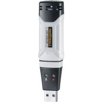
ClampMeter XP - Multimeter Laserliner - Free user manual and instructions
Find the device manual for free ClampMeter XP Laserliner in PDF.

| Product type | Clamp multimeter (clamp ammeter) |
| Brand | Laserliner |
| Model | ClampMeter XP |
| Dimensions (L x H x D) | 76 x 230 x 40 mm |
| Weight (batteries included) | 496 g |
| Power supply | 1 9V battery (6LR61) |
| Jaw opening | 48 mm |
| Display | LCD 50000 counts |
| Measurement rate | 3 measurements/s |
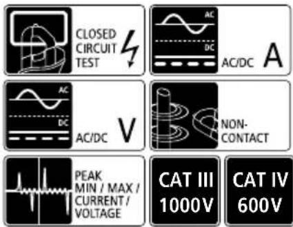
| Main functions | AC/DC current measurement 1000A, AC/DC voltage measurement 1000V, resistance, capacitance, frequency, temperature, diode test, continuity, non-contact voltage detection (100-600V AC), PEAK function, INRUSH, MIN/MAX, Hold, Bluetooth, flashlight, backlit display, auto power off, autorange |
| Overvoltage category | CAT III 1000V, CAT IV 600V |
| Protection | Double insulation (class II) |
| Operating conditions | 5 to 40°C, 80% RH max, max altitude 2000 m |
| Storage conditions | -20 to 60°C, 80% RH max |
| Bluetooth | Bluetooth LE 4.x, max range 10 m |
| Compliance | EU (RED, EMC, WEEE) |
| Maintenance and cleaning | Clean with a slightly damp cloth, avoid solvents; remove batteries for prolonged storage; annual calibration recommended |
| Available spare parts | Test leads (with/without cap), 9V battery |
| Warranty | See complete manual and specific conditions |
| General information | Auto power off function after 30 min; can be disabled; data transmission via mobile app (iOS/Android) |
Frequently Asked Questions - ClampMeter XP Laserliner
User questions about ClampMeter XP Laserliner
0 question about this device. Answer the ones you know or ask your own.
Ask a new question about this device
Download the instructions for your Multimeter in PDF format for free! Find your manual ClampMeter XP - Laserliner and take your electronic device back in hand. On this page are published all the documents necessary for the use of your device. ClampMeter XP by Laserliner.
USER MANUAL ClampMeter XP Laserliner
Laserliner
!
natural_image
Circular mechanical component with concentric rings and a small mark, no visible text or symbolsnatural_image
Circular mechanical component with concentric rings and a small black label (no readable text or symbols)AC/DC
500
natural_image
Circular mechanical component with concentric rings and a small diamond-shaped label (no readable text or symbols)natural_image
Circular mechanical component with gear-like structure and a label 'Hrs' pointing to its center (no other text or symbols)natural_image
Simple diagram of a transistor with two leads and one terminal, no text or symbols presentnatural_image
Circular mechanical component with concentric rings and a central knob, labeled Ω at the bottom (no text or symbols on the component itself)2.

natural_image
Simple electrical circuit diagram with two probes and a resistor labeled Ω (no text or symbols beyond basic components)natural_image
Circular mechanical component with concentric rings and a central hole, no visible text or symbolsDiodenprüfung

natural_image
Pure electrical circuit symbol for a diode with two terminals and polarity indicators (no text or labels)natural_image
Simple diagram showing two test tubes connected to a cylindrical component with plus and minus signs, no text or symbols present.Durchlassrichtung
natural_image
Circular mechanical component with concentric rings and a small inset detail (no visible text or symbols)Durch- gangsprüfung
natural_image
Illustration of two microphones with a musical note and sound waves, no text or symbols presentrotschwarzrotschw

natural_image
Two identical electronic devices with a musical note symbol between them (no text or labels)natural_image
Circular mechanical component with concentric rings and a small black label 'mV' (no readable text or symbols)AC/DC mV
natural_image
Circular mechanical component with concentric rings and a small label 'Vp Hz' (no readable text or symbols beyond the label)AC/DC V

Download on the App Store

ANDROID APP ON Google™ play


Completely read through the operating instructions, the „Warranty and Additional Information” booklet as well as the latest information under the internet link at the end of these instructions. Follow the instructions they contain. This document must be kept in a safe place and passed on together with the device.
Function/Application
Current and voltage multimeter for taking measurements in the range of overvoltage category CAT III up to max. 1000V / CAT IV up to max. 600V. The meter can be used to measure DC and AC voltages and direct and alternating currents, resistance and for continuity tests within the specified ranges. The device additionally features a PEAK function, a MIN/MAX display and a HOLD function. The device is equipped with a flashlight, an illuminated display and a Bluetooth interface for measured data transfer.
Symbols
Hazardous electrical voltage warning: Unprotected live components inside the devicehousing may pose a risk of electric shock.

Danger area warning

Protection class II: The test device has reinforced or double insulation.
CAT II
Overvoltage category II: Single-phase consumers that are connected to standard sockets, e.g. household appliances, portable tools.
CAT III
Overvoltage category III: Equipment in fixed installations and for applications where specific requirements with regard to the reliability and availability of equipment have to be met, e.g. circuit-breakers in fixed installations and devices used in industrial applications which are permanently connected to the fixed installation.
CAT IV
Overvoltage category IV: Devices such as electricity meters, overcurrent circuit breakers and ripple-control units, which are intended for use at or near the infeed into the electrical installation of buildings, and specifically from the main distribution to the supply system.
Safety instructions
- The device must only be used in accordance with its intended purpose and within the scope of the specifications.
- The measuring tools and accessories are not toys. Keep out of reach of children.
- Modifications or changes to the device are not permitted, this will otherwise invalidate the approval and safety specifications.
- Do not expose the device to mechanical stress, extreme temperatures or significant vibration.
- Exercise extreme caution when working with voltages higher than 24 V/AC rms or 60 V/DC. Touching the electrical conductors at such voltages poses a risk of life-threatening electric shocks.
- If the device comes into contact with moisture or other conductive residue, work must not be carried out under voltage. At and above voltages of 24 V/AC rms / 60 V/DC, the presence of moisture creates the risk of life-threatening electric shocks.
- Clean and dry the device before use.
- When using the device outdoors, make sure that the weather conditions are appropriate and/or that suitable protection measures are taken.
Laserliner
- In overvoltage category III (CAT III - 1000 V), the voltage between the test device and earth must not exceed 1000 V.
- In overvoltage category IV (CAT IV - 600 V), the voltage between the test device and earth must not exceed 600 V.
- Use the device together with the measuring equipment only in the correct overvoltage category (without protective cover CAT II - 1000 V; with protective cover CAT III - 1000 V and CAT IV - 600 V)
- The lowest overvoltage category (CAT), rated voltage and rated current apply when using the device together with the measuring equipment.
- Before taking any measurements, make sure that both the area to be tested (e.g. a line), the test device and the accessories used (e.g. connection cable) are in proper working order. Test the device by connecting it to known voltage sources (e.g. a 230 V socket in the case of AC testing or a car battery in the case of DC testing).
- The device must no longer be used if one or more of its functions fail or the battery charge is weak.
- The device must be disconnected from all power sources and measuring circuits before opening the cover to change the battery(ies) or fuse(s). Do not switch on the device with the cover open.
- Observe the safety precautions of local and national authorities relating to the correct use of the device and any prescribed safety equipment (e.g. electrician's safety gloves).
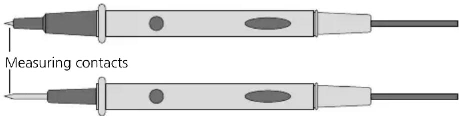
- If you have to take hold of the measuring spikes, do so by the grip sections only. Do not touch the measuring contacts whilst the measurement is being taken.
- Make sure that you always select the correct connections and rotary switch position with the correct measuring range for the measurement to be carried out.
- Do not work alone in the vicinity of hazardous electrical installations and only under the guidance of a qualified electrician.
- Disconnect the power supply to the electrical circuit before measuring or checking the diodes, resistance or battery charge.
- Check that all high-voltage capacitors are discharged.
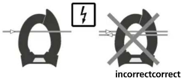
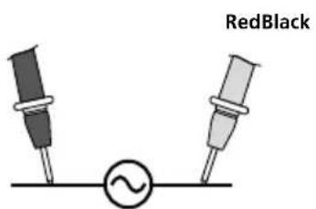
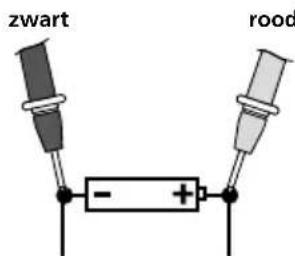
- When connecting to a voltage, always connect the black measuring lead first before the red lead. Follow the reverse procedure when disconnecting.
- Only the original measuring leads may be used. Their voltage, category and ampere rated powers must match those of the measuring device.
Additional information on use
Observe the technical safety regulations for working on electrical systems, especially: 1. Safely isolating from power supply, 2. Securing to prevent system being switched on again, 3. Checking zero potential, two-pole, 4. Earthing and short-circuiting, 5. Securing and covering adjacent live components.
Safety instructions
Using artificial, optical emission (OStrV)
LED outlet
- The device works with LEDs of risk group RG 0 (exempt, no risk) in accordance with the latest versions of applicable standards relating to photobiological safety (EN 62471:2008-09ff / IEC/TR 62471:2006-07ff).
- Radiation power: Peak wavelength equals 456 nm. Mean radiance is below the limit values of risk group RG 0.
- When used for the intended purpose and under reasonably foreseeable conditions, the accessible radiation of the LEDs is safe for the human eye and skin.
- Temporary, irritating optical effects (e.g. dazzling, flash blindness, afterimages, colour vision impairment) cannot be completely ruled out, especially under low ambient light conditions.
- Do not intentionally look directly into the radiation source for longer periods of time.
- No specific measures are required to ensure the limit values of risk group RG 0 are maintained.
Safety instructions
Dealing with electromagnetic radiation
- The measuring device complies with electromagnetic compatibility regulations and limits in accordance with the EMC Directive 2014/30/EU which is covered by the Radio Equipment Directive 2014/53/EU.
- Local operating restrictions - for example, in hospitals, aircraft, petrol stations or in the vicinity of people with pacemakers - may apply. Electronic devices can potentially cause hazards or interference or be subject to hazards or interference.
Safety instructions
Dealing with RF radiation
- The measuring device is equipped with a wireless interface.
- The measuring device complies with electromagnetic compatibility and wireless radiation regulations and limits in accordance with the RED 2014/53/EU.
- Umarex GmbH & Co. KG hereby declares that the ClampMeter XP radio equipment complies with the essential requirements and other provisions of the European Radio Equipment Directive 2014/53/EU (RED). The EU Declaration of Conformity can be found in its entirety at the following address: http://laserliner.com/info?an=clmexp
Test prods
With protective cap: CAT III up to max. 1000V / CAT IV up to max. 600V
Without protective cap: CAT II up to max. 1000V
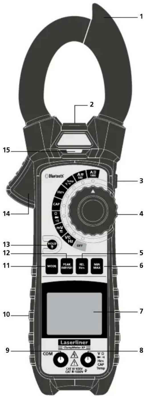
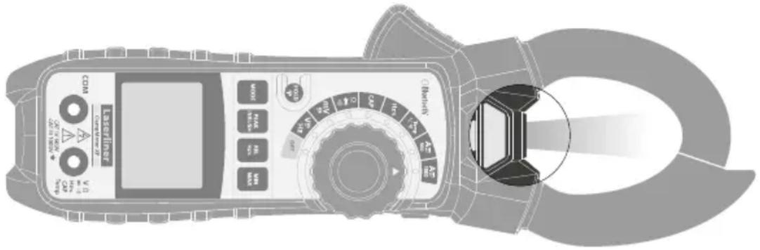
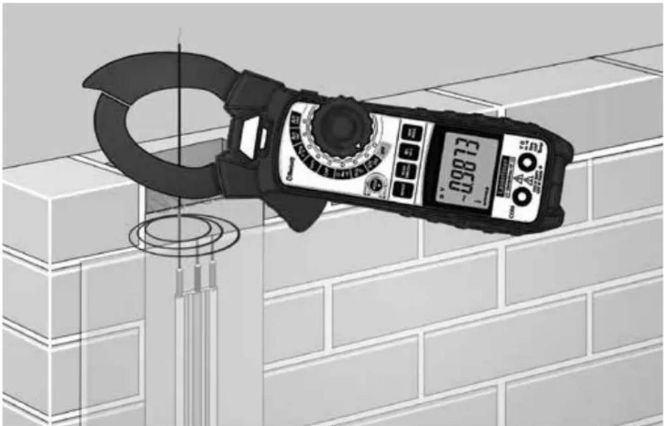
1 Current clamp
2 Flashlight
3 ON/OFF flashlight, Bluetooth ON/OFF
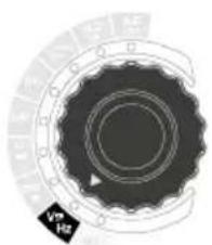
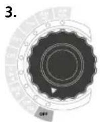
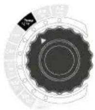
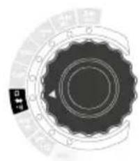
4 Rotary switch to set the measuring function
5 Comparison measurement (REL), frequency and duty factor measurement (Hz%)
6 MIN/MAX measurement in the ranges: voltage, hertz (frequency), percentage (duty factor), temperature and current
7 LCD
8 Red input socket (+)
9 Black COM socket (−)
10 Battery compartment at rear of device
11 Switch over measuring function
12 Voltage/current peak function
13 Hold current measured value, LCD lighting ON/OFF
14 Clamp opening button
15 Sensor (non-contact voltage detector)
Auto power off
m Milli (10 ^-3 ) (volt, ampere)
v Volt (voltage)
M Mega (ohm)
k Kilo (ohm)
Ω Ohm (resistance)
Continuity test
Diode test
n Nano ( 10^-9 ) (capacitance)
μ Micro (10 ^-6 ) (ampere, capacitance)
F Farad (capacitance)
Hz Hertz (frequency)
% Percentage (duty factor)
°F °Fahrenheit
°C ° Celsius
A Ampere (amperage)
Bluetooth active
DC measurements
■ Negative measured value
\~ AC measurements
Low battery charge
AUTO Automatic range selection
HOLD Current measured value is held
PMAX Lowest positive peak
PMIN Lowest negative peak
MAX Maximum value
MIN Minimum value
REL Comparison measurement
INRUSH Current peak function
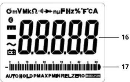
16 Measured value display
17 Bar graph display
Maximum limit values
| Function | Maximum limit values |
| Current AC/DC 1000A AC/DC | |
| Voltage AC/DC 1000V AC/DC | |
| Frequency, continuity, resistance, diode test, continuity, capacitance | 600V AC/DC |
| Temperature (°C/°F) 600V AC/DC |
AUTO OFF function
In order to preserve the batteries, the meter switches off automatically if it is left idle for 30 minutes.
Deactivation of AUTO-OFF function
1.2.3.
natural_image
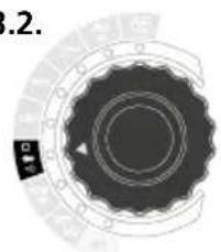
Circular mechanical component with concentric rings and a central arrow, no visible text or symbolsRotary switch set to „OFF“

Press and hold MODE button while at the same time turning the rotary switch to the required position
„APO d“ appears on the LC display
The “∅” symbol is not shown when auto power-off is deactivated. Auto power-off is reset by switching off the measuring device.
1 Insertion of batteries
Open the battery compartment (10) and insert batteries according to the symbols. Be sure to pay attention to polarity.
2 Attaching the test prods
To avoid the risk of injury, the test prods must always be kept in the holder at the rear of the device with the protective caps fitted when not in use and during transportation.
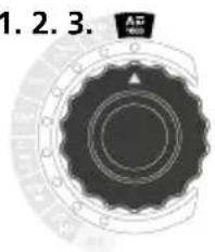
3Current measurement DC/AC
The test prods and the temperature sensor (K-type) must be disconnected before measuring AC/DC current.
1.2.3.
AC/DC
1000
natural_image
Circular mechanical component with concentric rings and a small black label (no readable text or symbols)AC/DC
500

AC/DC
selection
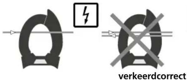
Place the ClampMeter around one wire

DC current measurement: Switch to DCA measurement without the line to be measured.
Allow sufficient time for the display to reset to zero (ZERO). If necessary, DC offsets can be zeroed with the REL button.
4Connection of test prods
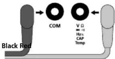
flowchart
graph LR
    A["Black Red"] --> B["COM"]
    B --> C["VΩ"]
    C --> D["Hrs"]
    D --> E["CAP Temp"]
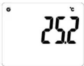
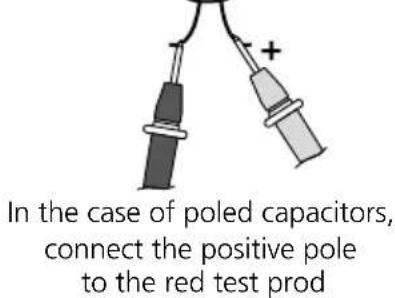
5 Contact temperature measurement
To measure contact temperature, connect the supplied temperature sensor (K-type) to the device. Ensure correct polarity.
natural_image
Circular mechanical component with concentric rings and a small diamond-shaped label (no readable text or symbols)After switching on, the ambient temperature is briefly displayed
2.3.1.

°C/°F selection
6 frequency and duty factor measurements
natural_image
Circular mechanical component with concentric rings and a small black label 'HCL' on the left side (no readable text or symbols beyond label)Frequency and duty factor measurements
2.3.

HZ/% selection
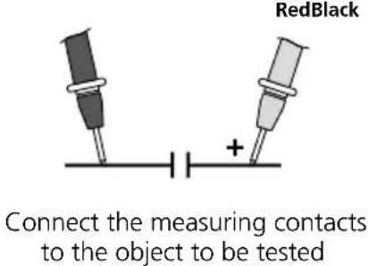
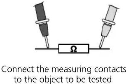
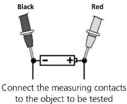
Connect the measuring contacts to the object to be tested
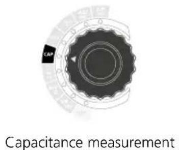
7. Capacitance measurement
1.
2.
3.
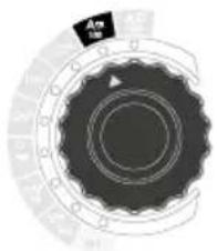
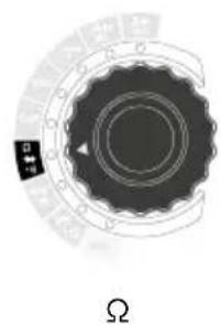
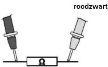
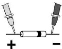
8 Resistance measurement
1.
natural_image
Circular mechanical component with concentric rings and a small black square on the left, labeled 'Ω' below (no text or symbols on the component itself)2.

Ω, diode check and continuity check selection
3.
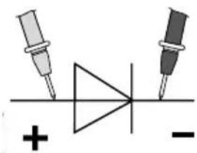
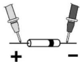
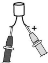
gDiode test
1.3.2.
natural_image
Circular mechanical component with concentric rings and a small black label (no readable text or symbols)Diode test

Ω, diode check and continuity check selection
natural_image
Pure electrical circuit symbol for a diode with two terminals and polarity indicators (no text or labels)
natural_image
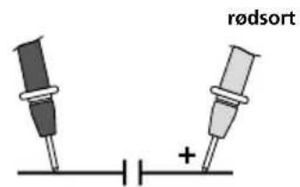
Simple diagram showing two test tubes connected to a cylindrical battery with polarity indicators (no text or labels)Forward direction
BlackBlack RedRed
If "O.L." appears on the display instead of a measured value, the diode has either been tested in the reverse direction or is faulty. If 0.0 V is measured, the diode is faulty or a short-circuit has occurred.
!
Components (7: Resistors, 8: Capacitors, 9: Diodes) can only be measured correctly in isolation. It may therefore be necessary to disconnect the components from the rest of the circuit.
!
To avoid incorrect results the measuring points must be free of dirt, oil, solder lacquer or similar.
!
The components must be off-circuit.
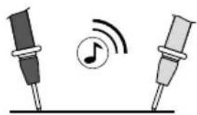
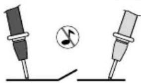
10urchgangsprüfung
1.3.2.
natural_image
Circular mechanical component with concentric rings and a small black square label (no readable text or symbols)continuity check

Ω, diode check and continuity check selection
natural_image
Illustration of two microphones with a musical note and sound waves, no text or symbols present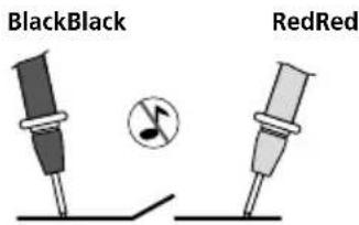
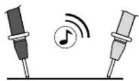
A measured value of < 50 ohms is recognised as continuity; this is confirmed by an audible signal. If „O.L.“ appears on the display instead of a measured value, either the measuring range has been exceeded or the measuring circuit is not closed or has been interrupted.

During the continuity check, the components must be de-energized.
11C/DC voltage measurements

natural_image
Close-up of a mechanical gear or cam component with concentric rings and mounting holes (no visible text or symbols)AC/DC mV

natural_image
Circular mechanical component with concentric rings and a small label (Vp Hz) at the bottom right, no readable text or symbols beyond the label.AC/DC V
-

AC/DC selection -
12 voltage detection, non-contact (AC warning)
The non-contact voltage detector integrated in the meter is able to detect AC voltages from 100 V to 600 V. Switch the device on and run the voltage sensor along the object to be tested (5 - 10 mm). The display (15) lights up if AC voltage is detected.

Non-contact voltage detection is not a substitute for conventional two-pole voltage testing. As the device detects an electrical field, it will react even to static charge.

The detector is inoperative when auto power-off switches off the measuring device or when the function selector switch is set to the OFF position.
12EAK function (voltage peak function)
The PEAK function detects the highest positive and lowest negative peak in an AC voltage or AC current wave form. The measured values are updated each time a higher positive or lower negative PEAK is detected.
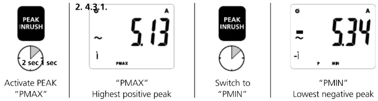
Briefly press the PEAK/INRUSH button to switch between PMAX and PMIN. To return to normal operation, keep the PEAK/INRUSH button pressed until „AUTO“ appears on the LC display.
14 RUSH function (current peak function)
The INRUSH function detects and displays current peaks that typically occur when switching on motors or other devices. To activate the function, briefly press the PEAK/INRUSH button. „INRUSH“ appears together with the detected inrush current on the LC display. To return to normal operation, briefly press the PEAK/INRUSH button.
13EL function (comparison measurement)
The comparison measurement function takes a measurement relative to a previously saved reference value. This enables the difference between the current measured value and the saved reference value to be displayed. Press the „REL“ button whilst a reference measurement is being taken in the corresponding measuring function. The display now shows the difference between the current measurement and the set reference value. Press the „REL“ button again to deactivate the function.
132 function
To select the frequency, with the measuring device set to AC voltage or AC current, keep the REL/HZ/% button pressed until „Hz“ appears on the LC display. To display the inrush cycle, again keep the REL/HZ/% button pressed until „%“ appears on the LC display. Press the „REL“ button again to deactivate this function.
17 AX/MIN function
The MAX/MIN function shows the highest and lowest measured values. The measured values are updated each time a higher or lower measurement is recorded. To activate the function, briefly press the MAX/MIN button. „MAX“ appears together with the highest value on the LC display. By briefly pressing the MAX/MIN button, the device switches from MAX to MIN, from MIN to the current measured value and from the actual measured value to MAX. „MIN“ appears when the lowest measured value is displayed and „MAX MIN“ appears when the current measured value is displayed. Keep the MAX/MIN button pressed to exit MAX/MIN function and return to normal operation.
13 function overview
The function described under point 13 to 17 are available in the measurement variable shown below:
| PEAK INRUSH | REL Hz% | MIN MAX | |
| Current measurement AC (1000 A) | ● / ● ● | / ● / ● ● | |
| Current measurement DC (1000 A) - / - | ● / - / - | ● | |
| Current measurement AC (500 A) | ● / ● ● | / ● / ● ● | |
| Current measurement DC (500 A) - / - | ● / - / - | ● | |
| Contact temperature measurement - / - | ● / - / - | ● | |
| Frequency measurement - / - | ● / - / -- | ||
| Duty factor measurement - / - | ● / - / -- | ||
| Capacitance measurement - / - - / - / -- | |||
| Resistance measurement - / - | ● / - / -- | ||
| Diode test - / - | ● / - / -- | ||
| Continuity test | - / - | ● / - / -- | |
| Voltage measurement AC | ● / - | ● / ● / ● ● | |
| Voltage measurement DC - / - | ● / - / - | ● |
19old function
The „Hold“ function enables you to keep the current measured value on the display. Press the „HOLD“ (13) button to activate and deactivate the function.
2 Auto range
The „Auto range“ function is activated automatically when the meter is switched on. Auto range searches for the best possible range for each measurement in the corresponding measuring functions.
21acklight
Long-press the button (13) to switch the backlighting on and off.
22ashlight function
Short-press the button (3) to switch the flashlight on and off.
Information on maintenance and care
Clean all components with a damp cloth and do not use cleaning agents, scouring agents and solvents. Remove the battery(ies) before storing for longer periods. Store the device in a clean and dry place.
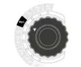
Calibration
The meter needs to be calibrated and tested on a regular basis to ensure it produces accurate measurement results. We recommend carrying out calibration once a year.
Data transfer
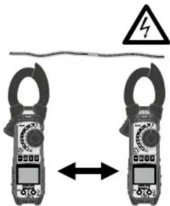
The device features a Bluetooth®* function that enables wireless data transfer to mobile devices with a Bluetooth®* interface (such as a smartphone or tablet).
The system prerequisites for a Bluetooth ^®* connection are specified at http://laserliner.com/info?an=ble
The device can set up a Bluetooth ^® * connection with Bluetooth 4.0 compatible devices.
The range is set to a maximum distance of 10 m from the terminal device and greatly depends on the ambient conditions such as the thickness and composition of walls, sources of interference as well as the transmit / receive properties of the terminal device.
Bluetooth ^® must be activated after switching on the device as the measuring system or measuring device is designed for very low power consumption.
A mobile device can link up to the active measuring device via an app.
Application (app)
An app is required to use the Bluetooth ^® * function.
You can download the app from the corresponding stores for the specific type of terminal device:


Make sure that the Bluetooth®* interface of the mobile device is activated.
After starting the app and activating the Bluetooth®* function, a connection can be set up between a mobile device and the measuring device. If the app detects several active measuring devices, select the matching device.
This measuring device can be connected automatically the next time it is switched on.
* The Bluetooth® word mark and the logo are registered trademarks of Bluetooth SIG Inc.
Technical data (Subject to technical alterations. 18W09)
| Function Range Resolution | Accuracy% of measured value (rdg)+ least significant digits | ||
| AC current50-60 Hz | 500.00 A 10 mA | ± (2,5% rdg ± 5 digits) | |
| 1000.0 A 0.1 A | |||
| DC current | 500.00 A 10 mA | ± (2,5% rdg ± 5 digits) | |
| 1000.0 A 0.1 A | |||
| AC voltage (Auto range) | 500.00 mV 0.01 mV | ± (1,0% rdg ± 30 digits) | |
| 5.0000 V 0.1 mV | |||
| 50.000 V 1 mV | |||
| 500.00 V 10 mV | |||
| 1000.0 V 0.1 V | ± (3,0% rdg ± 8 | digits) | |
| AC voltage (Auto range) | Frequency (Auto range)Accuracy: ± (1.0% rdg ±5 digits)Frequency range: 40 Hz ... 1 kHzSensitivity: >15 V RMS | ||
| Duty cycleAccuracy: 5% ... 95% ± (1,5% rdg ± 10 digits)Frequency range: 40 Hz ... 1 kHzSensitivity: >15 V RMS | |||
| DC voltage (Auto range) | 500.00 mV 0.01 mV | ± (1,0% rdg ± 8 digits) | |
| 5.0000 V 0.1 mV | |||
| 50.000 V 1 mV | |||
| 500.00 V 10 mV | |||
| 1000.0 V 0.1 V | ± (1,5% rdg ± 3 digits) | ||
| Resistance (Auto range) | 500.00 Ω 0.01 Ω ± (1,0% rdg ± 9 digits) | ||
| 5.0000 kΩ 0.1 Ω | ± (1,0% rdg ± 5 digits)50.000 kΩ 1 Ω | ||
| 500.00 kΩ 10 Ω | |||
| 5.0000 MΩ 100 Ω ± (2,0% rdg ± 10 digits) | |||
| 50.000 MΩ 1 kΩ ± (3,0% rdg ± 10 digits) | |||
| Capacitance (Auto range) | 500.00 nF 10 pF ± (3,5% rdg ± 40 digits) | ||
| 5000.0 nF 0.1 nF | ± (5,0% rdg ± 10 digits) | ||
| 50.000 μF 1 nF | |||
| 500.00 μF 10 nF | |||
| 5.000 mF 1 μF | |||
| Frequency (Auto range) | 50.000 Hz 0.001 Hz | ± (0,3% rdg ± 2 digits) | |
| 500.00 Hz 0.01 Hz | |||
| 5.0000 kHz 0.1 Hz | |||
| 50.000 kHz 1 Hz | |||
| 500.00 kHz 10 Hz | |||
| 5.0000 MHz | 100 Hz | ||
| 10.000 MHz | 1 kHz | ||
| Pulse width: 100 μs ... 100 msFrequency: 50 Hz ...100 kHzSensitivity: >15 V RMS | |||
| Duty cycle | 5% ... 95% | 0.1% ± (1,0% rdg ± 2 digits) | |
| Pulse width: 100 μs ... 100 msFrequency: 50 Hz ...100 kHzSensitivity: >15 V RMS | |||
| Temperature | -148 ... 1832°F | 0.1°F | ± (1% rdg ± 4.5°F) |
| -100 ... 1000°C | 0.1°C | ± (1% rdg ± 2.5°C) | |
| Function Range Max. input | |||
| AC current | Accuracy specified for 5% ... 100% of measured value | 1000 A | |
| DC current 1000 A | |||
| Function Range Input protection | |||
| AC voltage (Auto range) | 500 mV 600 AC/DC | ||
| 5V/50/500/1000 V 1000 AC/DC | |||
| Frequency: 50 Hz ... 1000 Hz | |||
| DC voltage | 500 mV 600 AC/DC | ||
| 5V/50/500/1000 V 1000 AC/DC | |||
| Resistance (Auto range) 600V AC | rms or 600V DC | ||
| Capacitance (Auto range) | 600V AC rms or 600V DC | ||
| Clamp opening | 48 mm | ||
| Diode test | Test current/voltage ≤ 0.3 mA /open circuit voltage < 2 V DC typical | ||
| Continuity test | Response threshold < 35Ω + 5Ω, test current < 0,5 mA | ||
| LCD | 0 ... 50000 | ||
| Measurement range | 3 measurements/sec. | ||
| Input resistance | 1,0 MΩ (VDC, VAC) | ||
| Protection class | II, double insulation | ||
| Overvoltage category | CAT III - 1000V, CAT IV - 600V | ||
| Pollution degree 2 | |||
| Operating conditions 5 ... 40°C, | 80%rH, no condensation, max. altitude 2000 m | ||
| Storage conditions | -20 ... 60°C, 80%rH, no condensation | ||
| Radio module operating data | Bluetooth LE 4.x interface Frequency band: ISM band 2400–2483.5 MHz, 40 channels Transmission power: max. 10 mWBandwidth: 2 MHz Bit rate: 1 Mbit/s; Modulation: GFSK/FHSS | ||
| Power supply | 1 x 6LR61 9V | ||
| Dimensions (W x H x D) | 76 x 230 x 40 mm | ||
| Weight (incl. batteries) | 496 g | ||
EU directives and disposal
This device complies with all necessary standards for the free movement of goods within the EU.
This product is an electric device and must be collected separately for disposal according to the European Directive on waste electrical and electronic equipment.
Further safety and supplementary notices at:
http://laserliner.com/info?an=cmxp
!
natural_image
Close-up of a mechanical gear or cam component with concentric rings and a small triangular feature, no visible text or symbols.natural_image
Circular mechanical component with concentric rings and mounting holes, no visible text or symbolsAC/DC
500

Omschakeling
AC en DC
natural_image
Circular mechanical component with concentric rings and a small labeled tag (no readable text or symbols)natural_image
Circular mechanical component with concentric rings and a small label 'Hrs' pointing to one end (no other text or symbols)natural_image
Simple diagram of a transistor with two terminals and a plus sign, no text or symbols presentnatural_image
Circular mechanical component with concentric rings and a small black indicator light, labeled Ω at the bottom (no text or symbols on the component itself)2.

Omschakeling Ω, diodetest en doorgangstest
3.
natural_image
Circular mechanical component with concentric rings and a small black label (no readable text or symbols)Diodetest

Omschakeling Ω, diodetest en doorgangstest

natural_image
Pure electrical circuit symbol for a diode with two terminals and polarity indicators (no text or labels)rood zwartzwartrood
natural_image
Simple diagram showing two test tubes connected to a cylindrical battery with polarity indicators (no text or labels)Doorlaatrichting
natural_image
Top-down view of a mechanical gear or cam component with concentric rings and a small inset detail (no text or symbols visible)Doorgangstest

Omschakeling Ω,
diodetest en
doorgangstest
natural_image
Illustration of two microphones with a musical note and sound waves, no text or symbols present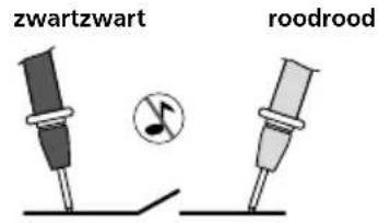
natural_image
Circular mechanical component with concentric rings and a small black arrow labeled 'mv' (no readable text or symbols beyond label)AC/DC mV

natural_image
Circular mechanical gear or cam component with concentric rings and a small label 'Vp Hz' (no readable text or symbols beyond the label)AC/DC V

Omschakeling AC en DC
3.
!
natural_image
Close-up of a mechanical gear or cam component with concentric rings and a small mark, no visible text or symbols.Drejekontakt på „OFF“
natural_image
Circular mechanical component with concentric rings and a small triangular feature, labeled 1.2.3 (no text or symbols on the component itself)AC/DC
1000

natural_image
Circular mechanical gear or cam mechanism diagram with concentric rings and a small black label (no readable text or symbols)AC/DC
500
natural_image
Circular mechanical component with concentric rings and a small triangular feature, no visible text or symbols.natural_image
Circular mechanical component with concentric rings and a small black label 'Hc' (no readable text or symbols beyond the label)Frekvens-, og duty-cycle-måling
natural_image
Circular mechanical component with concentric rings and a central arrow, no visible text or symbolsKapacitetsmåling
Forbind målekontakterne med måleobjektet
3.
natural_image
Simple diagram of a transistor with two terminals and a plus sign, no text or symbols presentVed kondensatorer med poler forbindes pluspolen med den røde målespids
8Modstandsmåling
natural_image
Cross-sectional view of a mechanical gear or cam component (no visible text or symbols)Ω
natural_image
Top-down view of a mechanical gear or cam mechanism with concentric rings and a small black component labeled 'B' (no text or symbols on the diagram itself)Diodetest

natural_image
Pure electrical circuit symbol for a diode with two terminals and a plus/minus signs (no text or labels)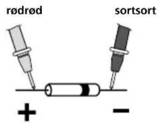
natural_image
Circular mechanical component with concentric rings and a small black square label (no readable text or symbols)Gennemgangstest
natural_image
Illustration of two microphones with a musical note and sound waves, no text or symbols present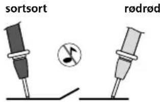
natural_image
Close-up of a mechanical gear or cam component with concentric rings and mounting holes (no visible text or symbols)AC/DC mV
natural_image
Circular mechanical component with concentric rings and a small labeled tag (no readable text or symbols)AC/DC V
!


Kontrollér, at Bluetooth®*-interfacet i den mobile enhed er aktiveret.
REL Mesure comparative
natural_image
Circular mechanical component with concentric rings and a central hole, no visible text or symbolsnatural_image
Circular mechanical component with concentric rings and a small black label (no readable text or symbols)AC/DC
500
natural_image
Circular mechanical component with concentric rings and a small diamond-shaped label (no readable text or symbols)natural_image
Circular mechanical component with concentric rings and a labeled section 'Hrs' (no other text or symbols)natural_image
Circular mechanical component with concentric rings and a central gear-like feature, no visible text or symbolsnatural_image
Simple diagram of a transistor with two terminals and a plus sign, no text or symbols presentnatural_image
Top-down view of a mechanical gear or cam component with concentric rings and flanges (no visible text or symbols)Ω
2.
natural_image
Circular mechanical component with concentric rings and a small black symbol at the bottom (no text or labels)Contrôle des diodes
noirnoir
natural_image
Simple diagram showing two test tubes connected to a cylindrical battery with polarity indicators (no text or labels)natural_image
Top-down view of a mechanical gear or cam component with concentric rings and a small inset detail (no text or symbols visible)Contrôle du passage
natural_image
Illustration of two microphones with a musical note and sound waves, no text or symbols presentrougerougenoir noir
natural_image
Two identical electronic devices with a musical note symbol between them (no text or labels)natural_image
Circular mechanical component with concentric rings and a central dark area, no visible text or symbolsAC/DC mV

natural_image
Circular mechanical gear or cam component with concentric rings and a small label 'Vp Hz' (no readable text or symbols beyond the label)AC/DC V
natural_image
Circular mechanical component with concentric rings and a central arrow, no visible text or symbolsCambiar el interruptor giratorio a "OFF"


natural_image
Circular mechanical component with concentric rings and a small black label (no readable text or symbols)AC/DC
500
natural_image
Circular mechanical component with concentric rings and a small diamond-shaped label (no readable text or symbols)Al encender se visualiza brevemente la temperatura ambiente
2.3.1.

Cambio entre ^ C y ^ F

natural_image
Circular mechanical component with concentric rings and a labeled section 'Hrs' (no other text or symbols)natural_image
Top-down view of a mechanical gear or cam component with concentric rings and a central hub (no text or symbols visible)natural_image
Simple diagram of a cylindrical object connected to two labeled probes (no text or symbols)natural_image
Cross-sectional view of a mechanical gear or cam component (no visible text or symbols)Ω
2.
natural_image
Circular mechanical component with concentric rings and a small black label (no readable text or symbols)natural_image
Pure electrical circuit symbol for a diode with two terminals and a plus/minus signs (no text or labels)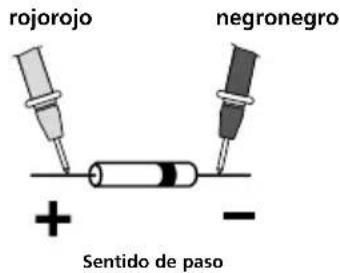
natural_image
Circular mechanical component with concentric rings and a small black square marker (no text or symbols)natural_image
Illustration of two microphones with a musical note and sound waves, no text or symbols present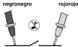
natural_image
Circular mechanical component with concentric rings and a small black arrow labeled 'mv' (no readable text or symbols beyond label)AC/DC mV

natural_image
Circular mechanical gear or cam component with concentric rings and a small labeled tag (no readable text or symbols)AC/DC V
natural_image
Two identical clamp meters connected by a wire, with a warning symbol above (no text or labels)
Download on the App Store

ANDROID APP ON Google™ play


SERVICE


Umarex GmbH & Co. KG
-Laserliner-