USER MANUAL EnergyLine Pro Fi Heat HAYWARD
natural_image
Exterior view of a modern HVAC air conditioning unit with a black fan and control panel (no visible text or symbols on the device itself)

text_image
R32
natural_image
Exterior view of a Hayward air conditioner unit with fan blades (no visible text or symbols)

text_image
R32
3.3 Raccordement hydraulique
text_image
Time switch
6
(Activer)

text_image
Time switch
12:00
00:00

text_image
01-01 2017 10:15:00 26.5°C
IN
SET
26.5°C
OUT 28.8°C
1
2 s
>>
4. INTERFACE UTILISATEUR (suite)
text_image
01-01 2017 10:15:00 ! 26.5°C
IN
SET
26.5°C
OUT 28.8°C
text_image
01-01 2017 10:15:00 ! 26.5°C
IN
26.5 °C
OUT 28.8 °C
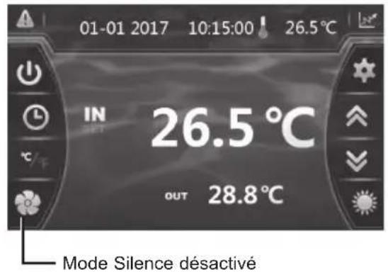
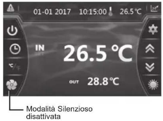
Mode Silence désactivé
Réglage du Timer

text_image
01-01 2017 10:15:00 26.5°C
IN
OUT 26.5 °C
28.8 °C


text_image
01-01 2017 10:15:00 ! 26.5°C
IN
SET
26.5 °C
OUT 28.8 °C
4. INTERFACE UTILISATEUR (suite)
natural_image
Exterior view of a gray industrial water heater with a hand valve and label (no readable text or symbols)
text_image
Technical diagram of an air conditioning unit with numbered components and labeled parts
ENPI4M / ENPI6M
| Rep | Désignation Réf. ENPI4M ENPI6M | | | |
| 1 V | Vanne 4 voies HWX20041437 | | √ | √ |
| 2 D | Détendeur électronique | HWX81000015 | √ | n/a |
| HWX81000016 n/a | | √ |
| 3 F | Filtre ø9.7-ø9.7 (∅28) HWX20041444 | | √ | √ |
| 4 D | Détecteur de débit d'eau HWX83000012 | | √ | √ |
| 5 C | Connecteur T ø9.52-2 x ø6.5(T) x 1.0 HWX304030000002 | | √ | √ |
| 6 T | Trappe d'accès électrique HWX320922029 | | √ | √ |
| 7 P | Panneau Droit HWX80700455 | | √ | √ |
| 8 P | Panneau décoratif droit HWX80900089 | | √ | √ |
| 9 C | Condenseur Titane PVC | HWX80600074 | √ | n/a |
| HWX80600096 n/a | | √ |
| 10 | Compresseur | HWX20000110448 | √ | n/a |
| HWX80100003 n/a | | √ |
| 11 | / | / | // | |
| 12 | / | / | // | |
| 13 | Bornier L-N-GND -5 connexions 4mm ^2 | HWX40003901 | √ | √ |
| 14 | Logo Hayward | HWX20000230596 | √ | √ |
| 15 | Ecran tactile couleur | HWX95005310612 | √ | √ |
| 16 | / | / | // | |
| 17 | Grille de protection ventilateur | HWX20000220169 | √ | √ |
| 18 | Hélice Ventilateur | HWX20000270004 | √ | √ |
| 19 | Moteur ventilateur DC | HWX20000330132 | √ | √ |
| 20 | Panneau décoratif gauche HWX80900088 | | √ | √ |
| 21 | Panneau Avant | HWX80900087 | √ | √ |
| 22 | Support Moteur | HWX80700248 | √ | √ |
| 23 | Evaporateur à ailette | HWX80600044 | √ | n/a |
| HWX80600100 n/a | | √ |
| 24 | Panneau Gauche | HWX80700455 | √ | √ |
| 25 | / | / | // | |
| 26 | Panneau supérieur | HWX301090200806 | √ | √ |
| 27 | Carte électronique Driver | HWX82300008 | √ | n/a |
| HWX82300007 n/a | | √ |
| 28 | Transformateur 230V~/12DC | HWX82600008 | √ | √ |
| 29 | / | / | // | |
| 30 | Relais K2 | HWX20000360297 | √ | √ |
| 31 | Bobine 20A 50Hz 5mH | HWX82500005 | √ | √ |
| 32 | Pressostat basse pression NO 0.30MPa/0.15MPa | HWX20000360157 | √ | √ |
| 33 | Prise de pression 40mm-1/2" | HWX20000140150 | √ | √ |
| 34 | Pressostat haute pression NC 3.2MPa/4.4MPa | HWX20013605 | √ | √ |
| 35 | Connecteur T ø6.5-2 x ø6.5(T) x 0.75T2M | HWX20001460 | √ | √ |
| 36 | / | / | // | |
| 37 | Capteur de pression | HWX20000360123 | √ | √ |
| 38 | Sonde Refoulement Compresseur 50kΩ-660mm | HWX83000026 | √ | √ |
| 39 | Sonde Température Air 5k-350mm | HWX83000049 | √ | √ |
| Sonde Sortie d'eau 5k-410mm | HWX83000050 | √ | √ |
| Sonde Entrée d'eau 5k-850mm | HWX83000052 | √ | √ |
| Sonde d'Aspiration compresseur 5k-560mm | HWX83000044 | √ | √ |
| Sonde de dégivrage 5k-680mm | HWX83000051 | √ | √ |
| 40 | Filtre CEM | HWX20003257 n/a | | √ |
6. ANNEXES (suite)
CONDITIONS DE GARANTIE
natural_image
Exterior view of a Hayward air conditioner unit with fan blades (no visible text or symbols)

text_image
R32
Installation & Instruction Manual
1. PREFACE 1
2. SPECIFICATIONS 4
2.1 Technical data for the swimming pool heat pump unit 4
2.2 Operating range 5
2.3 Dimensions 6
3. INSTALLATION AND CONNECTION 7
3.1 Functional Diagram 7
3.2 Heat pump unit 7
3.3 Hydraulic connection 8
3.4 Electrical connection 9
3.5 Initial start-up 10
3.6 Water flow setting 12
4. USER INTERFACE 13
4.1 General presentation 13
4.2 Setting the Date and Time 14
4.3 Timer function settings 14
4.4 Setting and visualisation of the set point 16
4.5 Locking and unlocking the touch screen 17
4.6 SILENT function settings 18
5. MAINTENANCE AND WINTERISING 21
5.1 Maintenance 21
5.2 Winterising 21
6. APPENDIX 22
6.1 Electrical diagrams 22
6.2 Heating priority wiring for monophasic pump 24
6.3 Exploded view and spare parts 26
6.4 Troubleshooting guide 28
6.5 Recording base 31
6.6 Warranty 32
1. PREFACE
Thank you for purchasing the Hayward heat pump for swimming pools. The Hayward FULL INVERTER heat pump has been designed to strict manufacturing standards meeting the highest levels of quality required.
Hayward heat pumps offer you exceptional performance throughout your bathing season by adapting wattage, power usage and noise levels to the heating requirements of your swimming pool thanks to FULL INVERTER control logic.

Read the instructions in this manual carefully before using the device.
Hayward heat pumps are designed exclusively to heat swimming pool water; do not use this equipment for any other purpose.
This manual includes all the necessary information for installation, trouble-shooting and maintenance.
Read this manual carefully before opening the unit or doing any maintenance work on it. The manufacturer of this product shall on no account accept any liability for injury to a user or damage to the unit further to any errors made during installation, trouble-shooting or unnecessary maintenance. It is particularly important to follow the instructions given in this manual at all times.
Otherwise the guarantee will be voided.
1. PREFACE (continued)

Safety instructions

This device contains R32.
Never use a refrigerant other than R32. Any other gaseous body mixed with R32 could cause abnormally high pressure and lead to a failure or pipes bursting and injuring people.
When carrying out repairs or maintenance work, never use copper tubes less than 0.8 mm thick.
As the heat pump is pressurized, never pierce the pipes or attempt any brazing. There is a risk of explosion.
Never expose the device to flames, sparks or other sources of ignition. It could explode and cause serious or even fatal injuries.
- If kept in storage, the heat pump should be kept in a well-ventilated room with a floor area of more than A_(m^2) as calculated by the following formula:
M is the quantity of refrigerant in the device in kg, and h0 is the storage height. If stored no the floor, h0 = 0.6 m.
- The heat pump is designed exclusively for installation outside buildings.
- The unit must be installed by qualified personnel.
- Do not install the heat pump on a support that risks intensifying the unit's vibrations.
- Make sure the support provided for the unit is strong enough to bear the weight of the unit.
- Do not install the heat pump anywhere liable to amplify its noise level or anywhere where its noise could disturb neighbours.
- All the electrical connections must be fitted by a professional qualified electrician in accordance with the standards in force in the country of installation, see §3.4.
- Shut off the main power supply and disconnecting switch before doing any electrical work. Forgetting to do so could cause electrocution.
- Before installing the unit, check that the earth cable is not cut or disconnected.
$$
A _ {\min} = (M / (2. 5 \times 0. 2 2 7 5 9 \times h 0)) ^ {2}.
$$
1. PREFACE (continued)
- Connect and properly tighten the power cable. A loose connection could damage electrical components.
- Exposing the heat pump to water or a humid atmosphere could cause electrocution. Be very careful.
- If you detect a fault or any abnormal situation, do not install the heat pump and contact your dealer immediately.
- All maintenance work should be done at the recommended intervals, as specified in this manual.
• Repairs must be carried out by qualified personnel.
- Only use OEM spare parts.
- Never use a cleaning method other than the one recommended in this manual.
This makes contains fluorinated greenhouse gases regulated by the Kyoto protocol. Do not release these gases into the atmosphere.
Type of refrigerant: R32
GWP(1) value: 675, based in the 4th report of the IPCC.
The quantity of refrigerant, based on the F-Gas regulation no. 517/2014, is stated on the unit's rating plate.
Period checks for leaks of refrigerant may be required by European or local legislation. Please contact your local dealer for more information.
(1) Global warming potential
2. SPECIFICATIONS
2.1 Technical data for the swimming pool heat pump unit
| Models | ENERGYLINE PRO INVERTER | ENPI4M ENPI6M | |
| Supply voltage V | | 220V-240V ~ / 1ph / 50Hz |
| Refrigerant / R32 | | |
| Load kg 0,50 0,65 | | | |
| Mass in teqCO2 | / 0,34 0,44 | | |
| Leak check frequency / No specific frequency, but an annual check is recommended |
| Min--Max heating capacity (a) kW 2,50--9,73 3,20--11,9 | | | |
| Min--Max electric input power(a) | kW 0,20--1,34 | 0,28--1,68 | |
| Min--Max continuous current rating (a) | A 1,33--6,02 | 1,34--7,32 | |
| Max--Min continuous power (COP) (a) | / | 12,32--7,12 | 11,51--7,10 |
| Min--Max heating capacity (b) kW 1,71--7,60 2,70--9,70 | | | |
| Min--Max electric input power(b) | kW 0,27--1,49 | 0,44--1,88 | |
| Max--Min continuous power (COP) (b) | / | 6,40--5,1 | 6,10--5,55 |
| Maximum continuous current | A | 7,30 8,90 | |
| Fuse rating | aM | 8 | 10 |
| Circuit-breaker curve D | D | 8 | 10 |
| Starting current | A | < CMS < CMS | |
| Hydraulic connection | mm | 50mm |
| Nominal water flow (a) | m3/h | 4,20 5,10 | |
| Max. loss of head on water | kPa | 3,3 | 4,5 |
| Compressor | / | DC Inverter Mitsubishi | DC Inverter Highly |
| Type | / Twin rotary | Twin rotary | |
| Quantity | / | 1 |
| Coil resistance at 20°C | Ohm | 1,91 | 0,788 |
| Fan | / | Axial |
| Quantity | | 1 |
| Diameter | mm 405 | 510 | |
| Number of blades | / | 3 |
| Motor | / | DC Inverter |
| Quantity | / | 1 | 1 |
| Rotation speed | rpm | 500--700 | 500-650 |
| Silent mode speed | rpm 300 | 400 | |
| Sound pressure level at 1 metre | dB(A) | 33--41 | 33-41 |
| Sound pressure level at 10 metres | dB(A) | 16--25 | 16--25 |
| Unit's net dimensions (L-W-H) | mm | 1046/400/768 |
| Weight | kg 53 | 65 | |
(a) Dry air 27°C - Relative humidity 78% - Water inlet temperature 26°C.
(b) Dry air 15°C - Relative humidity 71% - Water inlet temperature 26°C
2. SPECIFICATIONS (continued)
2.2 Operating range
Use the swimming pool heat pump unit within the following ranges of temperature and humidity to ensure safe and efficient operation.
| Heating mode  ng mode ng mode |  |
| Outside temperature -12°C – +35°C | +7°C – +43°C | |
| Water temperature +12°C – +40°C | +8°C – +40°C | |
| Relative humidity < 80% < 80% | | |
| Setting range from the set point +15°C – +32°C +8°C – +32°C | | |

If the temperature or humidity does not correspond to these conditions, the security measures could be activated and the swimming pool heat pump unit may no longer work.

The maximum heating temperature is set at 32^ C to prevent damage to the liners. Hayward cannot be held responsible if used at a temperature above +32^ C.
2. SPECIFICATIONS (continued)
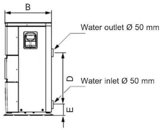
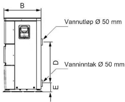
2.3 Dimensions
Models:
ENPI4M / ENPI6M
text_image
B
Water outlet Ø 50 mm
D
Water inlet Ø 50 mm
W
text_image
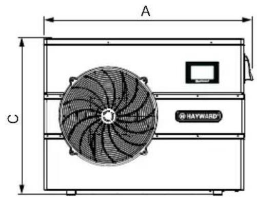
A
C
HAYWARD®
text_image
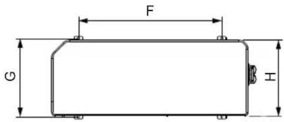
F
G
H
Unit: mm
| SIZE\TYPE | ENPI4M / ENPI6M |
| A 1046 | |
| B 400 | |
| C 768 | |
| D 350 | |
| E 110 | |
| F 615 | |
| G 428 | |
| H 400 | |
3. INSTALLATION AND CONNECTION
3.1 Functional Diagram
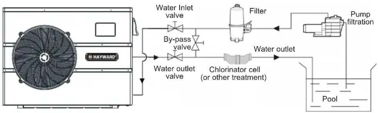
flowchart
graph LR
    A["HAYWARD"] --> B["Water inlet valve"]
    B --> C["Water outlet valve"]
    C --> D["Chlorinator cell (or other treatment)"]
    D --> E["Pump filtration"]
    E --> F["Filter"]
    F --> G["Water outlet"]
    G --> H["Pool"]
Note : The swimming pool heat pump unit is sold without any treatment or filtration equipment. The components presented in the diagram are spare parts to be supplied by the installer.
3.2 Heat pump unit

Place the heat pump outdoors and away from any enclosed technical space.
Placed under a shelter, the minimum required distances mentioned below must be respected in order to avoid any risk of air recirculation and a deficiency in the unit's overall performance.
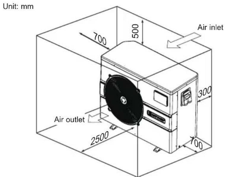
text_image
Unit: mm
700
500
Air inlet
300
Air outlet
2500
700
3. INSTALLATION AND CONNECTION (continued)

It is advised to install the unit on a dissociated cement block or a mounting bracket designed for this use and to set up the unit on the supplied rubber bushing (fastenings and washers not supplied).
The maximum installation distance between the unit and the swimming pool is 15 metres.
The total length of the piping to and from the unit is 30 metres.
Insulate both the above ground and buried hydraulic piping.
The heat pump must be installed at a minimum distance from the pool in compliance with NF C 15-100 (3.5 m from the water for France) or in compliance with installation standards applicable in other countries.
Do not install the heat pump close to a heat source.
For installation in snowy regions we recommend sheltering the machine to avoid snow accumulating on the evaporator.
3.3 Hydraulic connection
The unit is supplied with two 50 mm ∅ union connections. Connect the water inlet to the heat pump coming from the filtration group then connect the water outlet to the heat pump at the water conduit going to the pool (see diagram below).
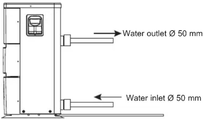
text_image
Water outlet Ø 50 mm
Water inlet Ø 50 mm
Install a by-pass valve between the heat pump entrance and exit.

If an automatic distributor or an electrolyser is used, it should be installed imperatively after the heat pump with the goal of protecting the titanium condenser against an elevated concentration of chemicals.

Be sure to install the by-pass valve and the supplied union connections at the water inlet and outlet level in order to simplify purging during the winter period and to facilitate access when disassembling for maintenance.
3. INSTALLATION AND CONNECTION (continued)
3.4 Electrical connection

Electrical installation and wiring for this equipment must be in conformity with local installation standards.
| F NF C15-100 GB BS7671:1992 | | |
| D DIN VDE 0100-702 EW EVHS-HD 384-7-702 | | |
| A ÖVE 8001-4-702 H MSZ 2364-702/1994/MSZ 10-553 1/1990 | | |
| E UNE 20460-7-702 1993,RECBT ITC-BT-31 2002 | M MSA HD 384-7-702.S2 | |
| IRL Wiring Rules + IS HD 384-7-702 PL PN-IEC 60364-7-702:1999 | | |
| I CEI 64-8/7 CZ CSN 33 2000 7-702 | | |
| LUX | 384-7.702 S2 | SK | STN 33 2000-7-702 |
| NL | NEN 1010-7-702 | SLO | SIST HD 384-7-702.S2 |
| P RSIUEE | TR TS IEC 60364-7-702 |

Verify that the available electrical power supply and the network frequency correspond to the required operating current taking into account the appliance's specific location, and the current required to supply any other appliance connected to the same circuit.
ENPI4M 230V\~ +/- 10 % 50 Hz 1 Phase
ENPI6M 230V\~ +/- 10 % 50 Hz 1 Phase
See the corresponding wiring diagram in the appendix.
The connection box is located on the right side of the unit. Three connections are designed for the power supply and two are for controlling the filter pump (Enslavement).
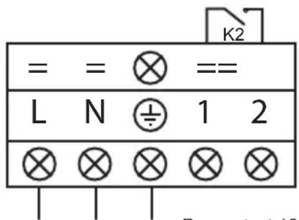
text_image
= = ⊗ ==
L N ⊕ 1 2
⊗ ⊗ ⊗ ⊗ ⊗
Power supply 230V\~ / 50Hz
Dry contact 16 A max potential free.
Priority heating function
3. INSTALLATION AND CONNECTION (continued)

The electrical power supply must have, when appropriate, a fuse protection device like a feed motor (aM) or D curve circuit breaker as well as a differential circuit breaker 30mA (see following table).
| Models | ENPI4M ENPI6M | |
| Power supply | V/Ph/Hz | 230V 50Hz | 230V 50Hz |
| aM type fuse calibre | A 8 aM | 10 aM | |
| Curve D circuit breaker | A 8 D | 10 D | |
| Cable section | mm ^2 | 3G 2,5 3G 2,5 | |

Use an RO 2V/R 2V or equivalent power cord.

The cables sections are given for a maximum length of 25 m. They must however be checked and adjusted according to the installation conditions.

Always shut down the main power supply before opening the electrical control box.
3.5 Initial start-up
Start-up procedure - After installation is complete, follow these steps:
1) Rotate the fans by hand to verify that they can turn freely by hand, and that the turbine is correctly affixed to the motor shaft.
2) Ensure that the unit is connected correctly to the main power supply (see the wiring diagram in the appendix).
3) Activate the filtration pump.
4) Verify that all water valves are open and that the water flows toward the unit before switching on the heating or cooling mode.
5) Verify that the drainage hose is correctly affixed and that it causes no obstructions.
6) Activate the unit power supply, then press the On/Off button 📄 on the control panel.
7) Ensure that the alarm signal ( ) does not light up red. If necessary see the troubleshooting guide (see § 6.4).
3. INSTALLATION AND CONNECTION (continued)
8) Set the water flow using the by-pass valve (see § 3.6 and 2.1), as provided for by each model, to obtain an Entry/Exit temperature of 2^ C.
9) After running for several minutes, verify that the air exiting the unit is cool (between 5 and 10°).
10) With the unit operating, turn off the filter pump. The unit should automatically turn off and display error code E03 (See § 6.4).
11) Allow the unit and the pool pump to run 24 hours per day until the desired water temperature has been reached. When the set water inlet temperature is reached, the unit will turn off. It will automatically restart (as long as the pool pump is running) if the pool temperature is at least 0.5^ C below the set temperature.
Water flow switch - The unit is equipped with a flow switch that turns on the heat pump when the pool filtration pump is running, and deactivates it when the filtration pump is out of order. If the water is low, the E03 alarm code will appear on the regulator (See § 6.4).
Time delay - The unit is equipped with a time delay of 3 minutes in order to protect the control circuit components, to eliminate restart cycling and contactor chatter. Thanks to this time delay, the unit automatically restarts approximately 3 minutes after each control circuit interruption. Even a brief power interruption will activate the restart time delay.
3. INSTALLATION AND CONNECTION (continued)
3.6 Water flow setting
With the water entry and exit valves being open, adjust the by-pass valve in order to obtain a difference of 2^ between the inflow and outflow temperature (see principle diagram § 3.1). You can verify the switch by seeing the entry/exit temperatures directly on the control panel.
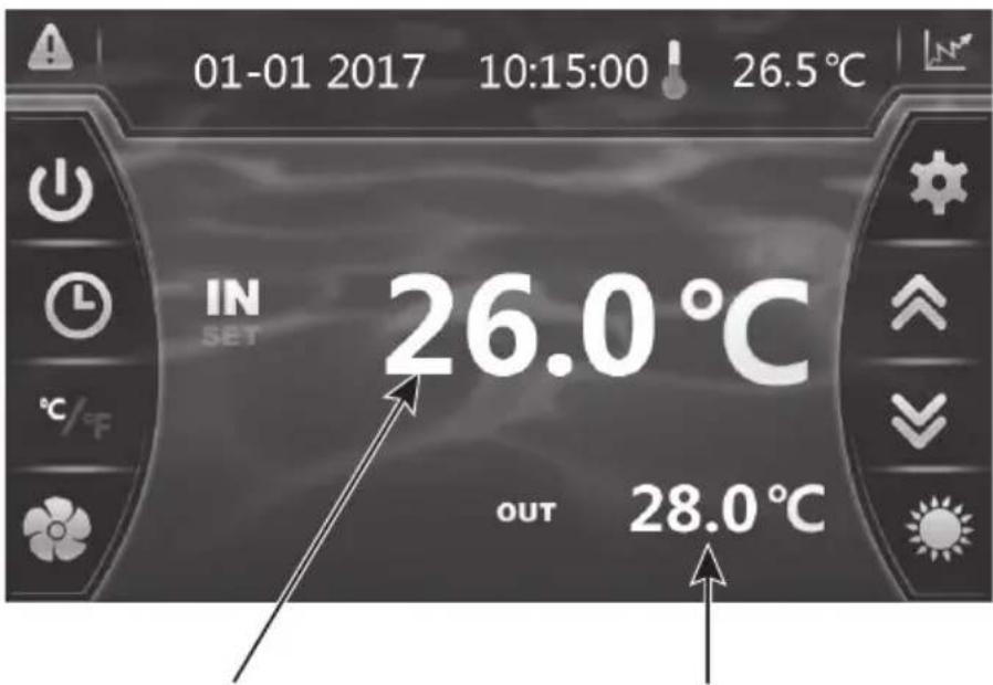
text_image
01-01 2017 10:15:00 26.5°C
IN
SET
26.0°C
OUT 28.0°C
Water inlet temperature Water outlet temperature
Note: Opening the by-pass valve creates a weaker flow, which leads to an increase in T .
Closing the by-pass valve creates a stronger flow, which leads to a decrease in T .
4. USER INTERFACE
4.1 General presentation
The heat pump is equipped with a digital control panel with a touch screen, electronically connected and pre-set at the factory in heating mode.
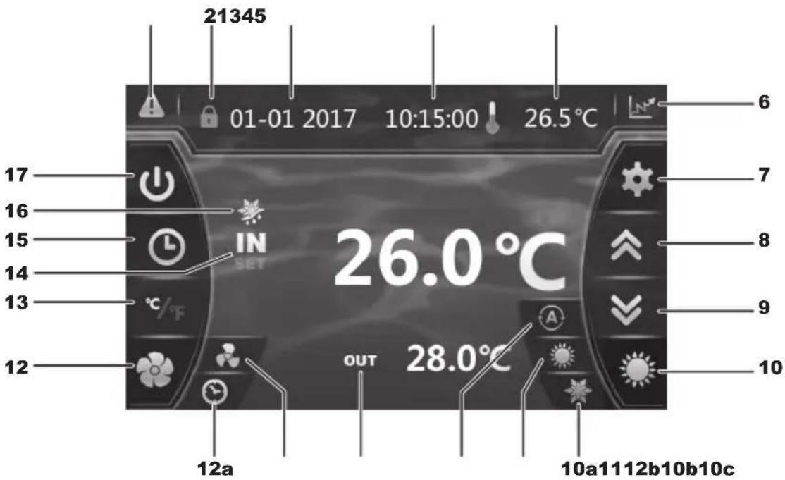
text_image
21345
01-01 2017 10:15:00 26.5°C
IN
SET
26.0°C
OUT 28.0°C
12a
10a1112b10b10c
Legend
| 1 Al |  (blinking red) (blinking red) |
| 2 Lc |  d screen d screen |
| 3 D |  |
| 4 H |  |
| 5 O |  de temperature de temperature |
| 6 |  Recording base (Water temperature and power consumption) Recording base (Water temperature and power consumption) |
| 7 R |  ng settings and saving ng settings and saving |
| 8 S |  up / Increase up / Increase |
| 9 S |  down / Decrease down / Decrease |
| 10 C | Operating mode selection |
| 10a |  ng mode ng mode |
| 10b |  | ng mode |
| 10c |  | matic mode |
| 11 V |  | Output temperature |
| 12 S |  | ting silence mode |
| 12a |  | ng silence mode timer |
| 12b |  | Silence mode and activation light |
| 13 C |  | version °C / °F |
| 14 V |  | Input temperature |
| 15 |  | Setting the Timer date and time ON/OFF |
| 16 D |  | st mode |
| 17 C |  | Off |
4. USER INTERFACE (continued)
OFF Mode
When the heating pump is in sleep mode (OFF Mode), the button is grey.
ON Mode
When the heating pump is running or regulating (ON Mode), the button lights up green.
4.2 Setting the Date and Time

text_image
01-01 2017 10:15:00 26.5°C
IN
OUT 26.5°C
28.8°C
Timer
2
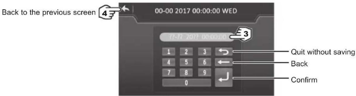
text_image
Back to the previous screen
00-00 2017 00:00:00 WED
1 2 3
4 5 6
7 8 9
0
3
Quit without saving
Back
Confirm

Enter all the fields (Day/Month/Year, Hour/Minute/Second before confirming, otherwise the changes will not be saved.
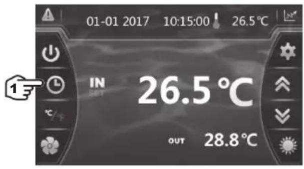
4.3 Timer function settings
Setting this function is necessary if you would like to run the heat pump for a shorter period than what is defined by the filtration clock. Therefore, you can program a deferred start and an anticipated stop or simply stop a certain timeframe from running (at night, for example).
It is possible to set one Start Timer and one Stop Timers.
4. USER INTERFACE (continued)

text_image
01-01 2017 10:15:00 26.5°C
IN
OUT 26.5°C
OUT 28.8°C


text_image
Timer
2
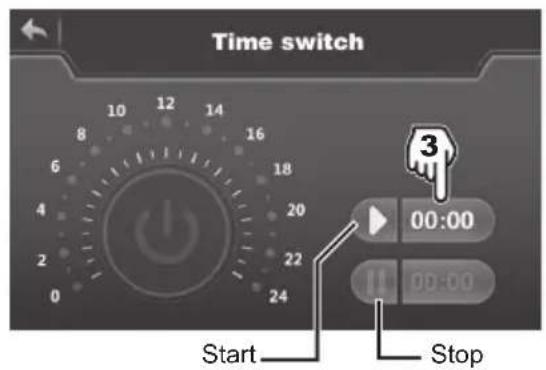
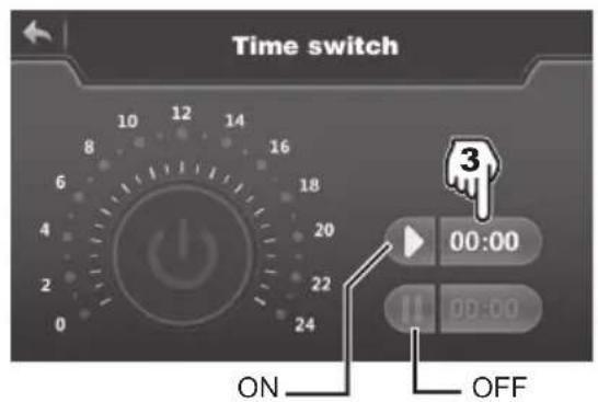
text_image
Time switch
Start
Stop


text_image
Time switch
12
1 2 3
5 6
7 8 9
0
12:00
00:00
(Confirm)
text_image
Time switch
12:00
00:00
6
(Activate)

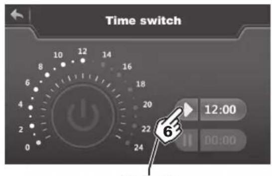
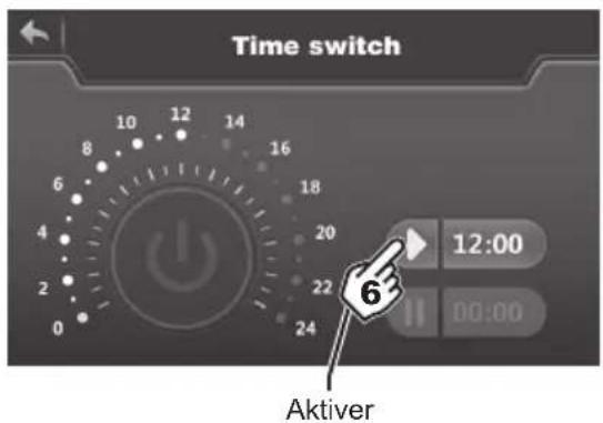
text_image
Time switch
12:00
00:00

Blue highlighting = Activated
Grey = Deactivated

The setting step is "hour to hour".
- Once the start time has been set, press (step 6) to activate the Timer. The symbol and time now have blue highlighting.
- Repeat steps 3 to 6 to set and activate the stop time ( )
- When the settings are complete, the operating range of the heat pump is highlighted in green and the highlight range is yellow.
- Press twice on to return to the main screen.
4. USER INTERFACE (continued)
4.4 Setting and visualisation of the set point
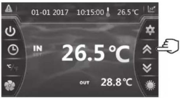
text_image
01-01 2017 10:15:00 26.5°C
IN 26.5°C
OUT 28.8°C
In Mode "OFF" or Mode "ON"
Press the button to display the set point, then press on pour to set the set point you wish.
Confirm by pressing and you will return to the main screen automatically.

The setting is made with a precision of 0.5^ C .

It is recommended to never exceed 30^ C to avoid alteration of the liners.
4. USER INTERFACE (continued)
4.5 Locking and unlocking the touch screen
The control screen locks automatically after one minute (default setting). It is possible to adjust the time before the screen locks automatically to between 1 and 10 minutes, or simply to cancel this function.
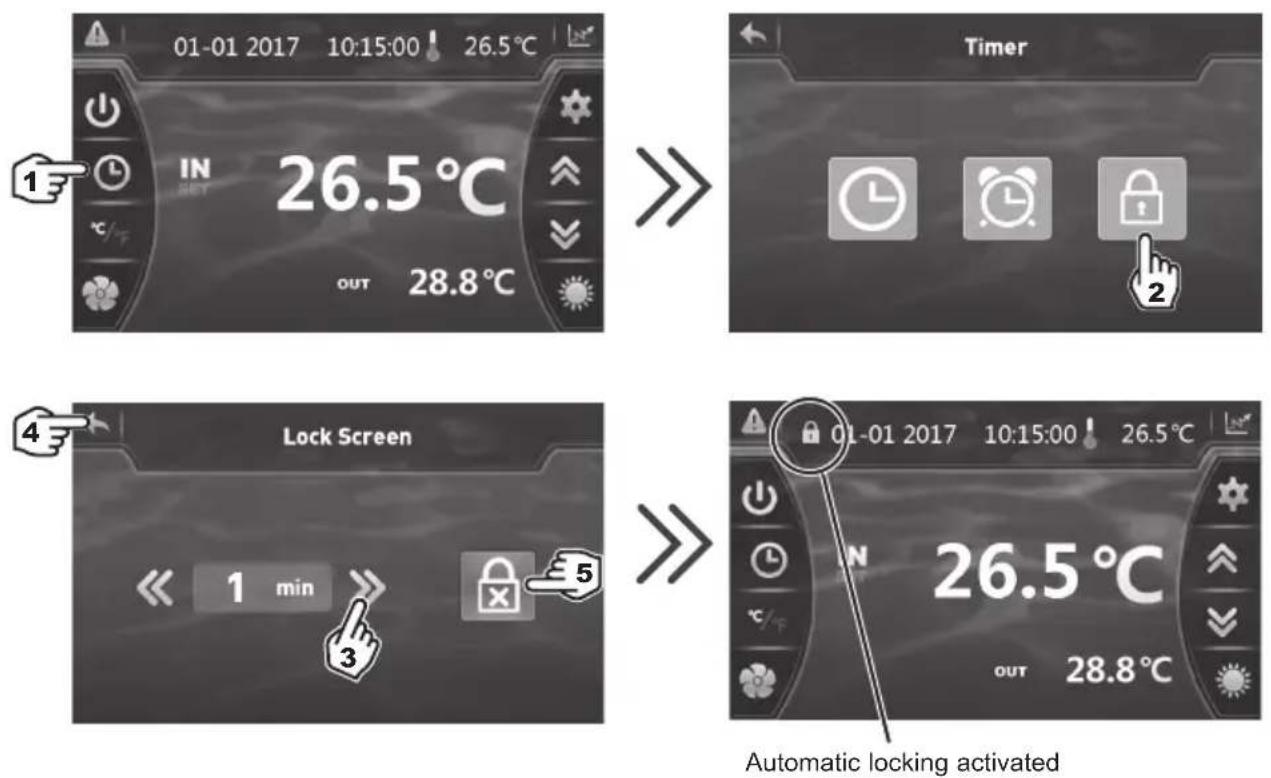
3) Set the time to between 1 and 10 minutes. Saving is automatic.
4) Press twice to return to the main screen.
5) To deactivate automatic locking press
To unlock the screen, press (anywhere) on the screen for 2s.
Enter the code "22" and confirm by pressing EN

text_image
01-01 2017 10:15:00 26.5°C
IN
SET
26.5°C
OUT 28.8°C
1
2 s
>>
4. USER INTERFACE (continued)
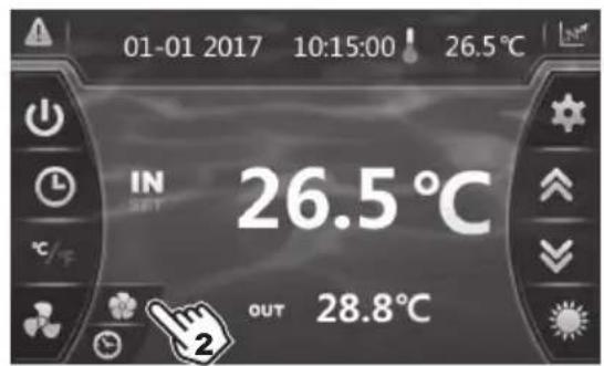
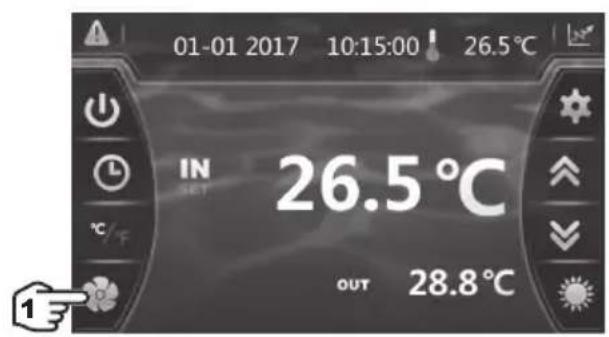
4.6 SILENT function settings
Silence mode enables the heat pump to be used in economic and very silent mode when the heating needs are low (maintaining the pool temperature or need for ultra-silent operation).
This function can be Activated/Deactivated manually or using a Timer.
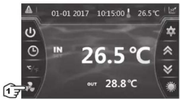
Manual Activation
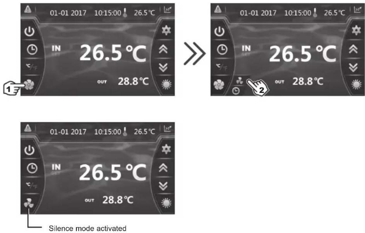
4. USER INTERFACE (continued)
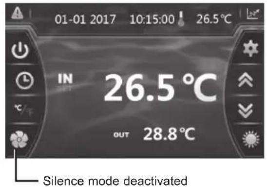
Manual Deactivation
text_image
01-01 2017 10:15:00 26.5°C
IN 26.5 °C
OUT 28.8 °C

text_image
01-01 2017 10:15:00 ! 26.5°C
IN
SET
26.5°C
OUT 28.8°C
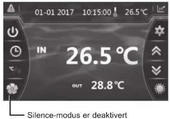
text_image
01-01 2017 10:15:00 ! 26.5°C
IN
26.5 °C
OUT 28.8 °C
Silence mode deactivated
Setting the Timer
text_image
01-01 2017 10:15:00 26.5°C
IN
OUT 26.5 °C
28.8 °C


text_image
01-01 2017 10:15:00 ! 26.5°C
IN
SET
26.5 °C
OUT 28.8 °C
4. USER INTERFACE (continued)
Setting the Timer (continued)

text_image
Mute Timer
ON OFF
1
00:00
2
00:00
Mute Timer
ON OFF
1 2 3
4 5 6
7 8 9
0
20:00
|| 08:00
Confirm
1) Start time, input and confirmation.
2) End time, input and confirmation.
3) Confirm.

text_image
Mute Timer
ON
OFF
20:00
08:00
4) Activation.
5) Deactivation.
6) Back to the main screen.

The setting step is "hour to hour".
Once the Timer is activated, it is active 7 days a week.
5.1 Maintenance
These maintenance operations must be carried out once per year in order to guarantee the longevity and the good working condition of the heat pump.
- Clean the coil with the help of a soft brush or jet of air or water (Warning, never use a high pressure cleaner).
- Verify that the drains flow well.
- Verify the tightening of the hydraulic and electrical connections
- Verify the hydraulic sealing of the condenser.
- Have the leak-tightness of the cooling circuit to the leak detector checked by an accredited professional.

Before any maintenance operation, the heating pump must be disconnected from any electrical current source. The maintenance operations must only be carried out by personnel that is qualified and authorised to handle liquid refrigerants.
5.2 Winterising
- Put the heat pump in "OFF" mode.
- Cut the power supply to the heat pump.
- Empty the condenser with the help of the drain to avoid any risk of deterioration. (high risk of freezing).
- Close the by-pass valve and unscrew the entry/exit connection unions.
- Eliminate the maximum amount of residual stagnant water from the condenser with the help of an air gun.
- Close the water entry and exit areas of the heating pump to avoid introducing foreign bodies.
- Cover the heating pump with a dedicated winterising case.

Any damage caused by poor winterising maintenance will lead to cancellation of the warranty.
6. APPENDIX
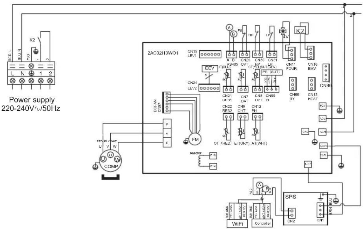
6.1 Electrical diagrams
ENPI4M
text_image
Power supply
220-240V√/50Hz
RED L
BLU N
Y/G
L N 1 2
K2
CN15 LEV1
2AC32I13WO1
CN15
A B FS HP LP 4V K2
RS485 OV T HP CT(VELSUT(SEN)
CN29 CN30 CN31
LEV2
ECV IT(BLU)
CN24
CN21 CN7 CN5 CN9
RES1 OAT OPT PL CN66 CN18 EMV
DN22 CN9 CN12
RES2 OH T PH
OT (RED) ET(GRY) AT(WHT)
FM
DCFAN
CN97
u v w
COMP
reactor P+30 P+40
RED BLK WHT V W
WiFi BLK CND BLK CND BLK CND BLK CND BLK CND BLK CND BLK CND BLK CND BLK CND BLK CND BLK CND BLK CND BLK CND BLK CND BLK CND BLK CND BLK CND BLK CND BLK CND BLK CND BLK CND BLK CND BLK CND BLK CND BLK CND BLK CIND
Controller
SPS
CN2 CN1 BRN BU
CN1
AT : AIR TEMPERATURE SENSOR
LP : LOW PRESSURE SWITCH
COMP : COMPRESSOR OT : OUTLET WATER TEMPERATURE SENSOR
CT : EVAPORATOR TEMPERATURE SENSOR
SUT : SUCTION TEMPERATURE SENSOR
EEV : ELECTRONIC EXPANSION VALVE
4V : 4 WAYS VALVE
FM : FAN MOTOR K2 : DRY CONTACT 16 A MAX
ET : DISCHARGE TEMPERATURE SENSOR
FS : WATER FLOW SWITCH
HP : HIGH PRESSURE SWITCH PS : PRESSURE SENSOR
IT : WATER INLET TEMPERATURE SENSOR
6. APPENDIX (continued)
ENPI6M
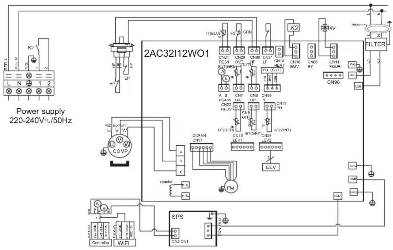
text_image
Power supply
220-240V^/50Hz
RED L
BLU N
Y/G
K2
L
N
1
2
HP
EP
EP
HP
IT(BLU)
FS UP
GRN
CN21
RES1
SUT(GRN)
CN29
OVT
CT(YE)
CN30
HP
CN31
LP
CN13
HEAT
PS (SUT)
BN
CN18
EMV
CN66
RY
CN11
FOUR
CN96
FILTER
L1
N1
A B
RS485
CN22
RES2
CN7
OAT
CN8
OPT
CN99
PL
CN12
PH
AT(WHT)
A B
RS485
CN22
RES2
CN9
OPT
CN99
OT(RED)
ET(GRY)
CN15
LEV1
CN24
LEV2
5
EEV
DCFAN
CN97
FM
reactor
P13L
P14L
SPS
CN2 CN1
BRN FLU
RLN
AT : AIR TEMPERATURE SENSOR
LP : LOW PRESSURE SWITCH
COMP : COMPRESSOR OT : OUTLET WATER TEMPERATURE SENSOR
SUT : SUCTION TEMPERATURE SENSOR
CT : EVAPORATOR TEMPERATURE SENSOR
4V : 4 WAYS VALVE
EEV : ELECTRONIC EXPANSION VALVE
FM : FAN MOTOR K2 : DRY CONTACT 16 A MAX
ET : DISCHARGE TEMPERATURE SENSOR
FS : WATER FLOW SWITCH
HP : HIGH PRESSURE SWITCH PS : PRESSURE SENSOR
IT : WATER INLET TEMPERATURE SENSOR
6. APPENDIX (continued)
6.2 Heating priority wiring for monophasic pump
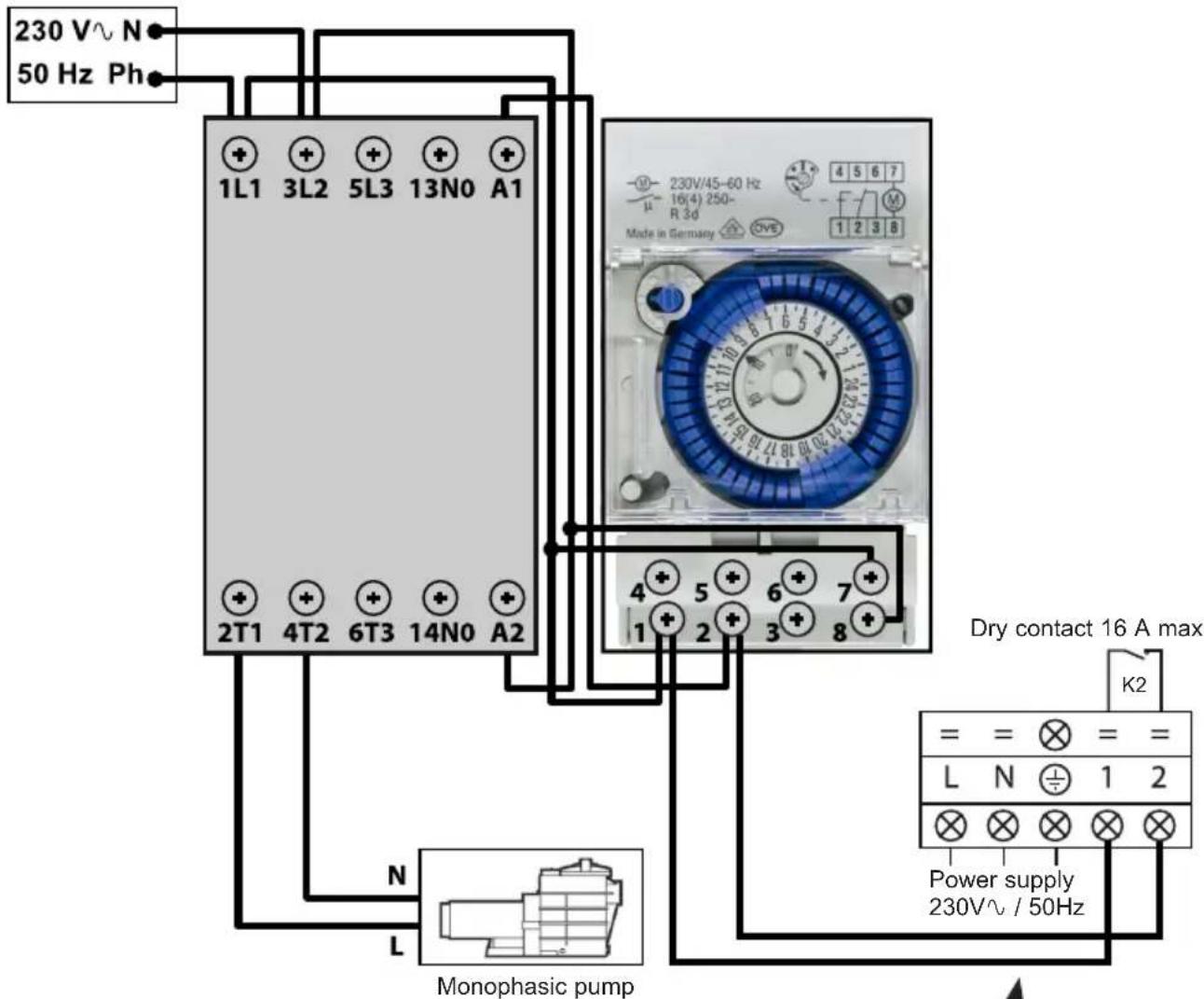
text_image
230 V~ N
50 Hz Ph
1L1 3L2 5L3 13N0 A1
2T1 4T2 6T3 14N0 A2
Monophasic pump
4 5 6 7
1 2 3 8
Made in Germany
230V/45-60 Hz
16(4) 250-
R 3d
Dry contact 16 A max
K2
Power supply
230V~ / 50Hz
Terminals 1 and 2 deliver a potential-free dry contact, 230V\~ / 50 Hz, no polarity.
Wire terminals 1 and 2 as indicated in the diagram above, to activate the operation of the filtration pump in 2-minute cycles each hour if the temperature of the pool is lower than the set point.

Never connect the power supply of the filtration p directly to terminals 1 and 2.
natural_image
Exterior view of a gray industrial water heater with a hand valve and label (no readable text or symbols)
Page left intentionally blank
6. APPENDIX (continued)
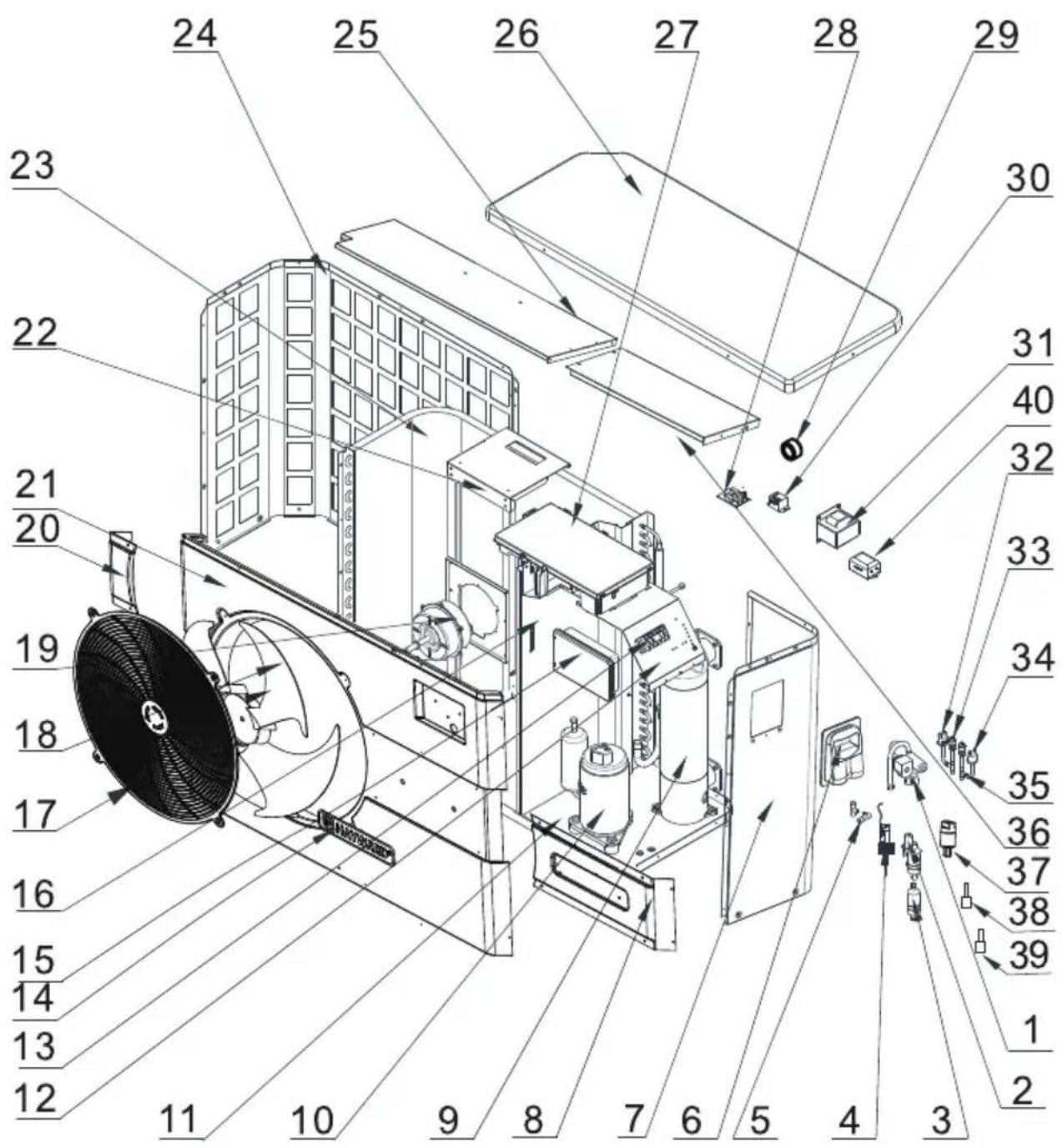
6.3 Exploded view and spare parts
ENPI4M / ENPI6M
text_image
Technical diagram of an air conditioning unit with numbered components and labeled parts
6. APPENDIX (continued)
ENPI4M / ENPI6M
| Mark | Description Ref. ENPI4M ENPI6M | | | |
| 1 4 | ways valve HWX20041437 | | ✓ | ✓ |
| 2 | Electronic expansion valve | HWX81000015 | ✓ | n/a |
| HWX81000016 n/a | | ✓ |
| 3 Filter ø9.7-ø9.7 (∅28) HWX20041444 | | ✓ | ✓ |
| 4 Water flow detector HWX83000012 | | ✓ | ✓ |
| 5 T connector ø9.52-2 x ø6.5(T) x 1.0 HWX304030000002 | | ✓ | ✓ |
| 6 Access hatch HWX320922029 | | ✓ | ✓ |
| 7 Right panel HWX80700455 | | ✓ | ✓ |
| 8 Right decorative panel HWX80900089 | | ✓ | ✓ |
| 9 Titanium/PVC condenser | HWX80600074 | ✓ | n/a |
| HWX80600096 n/a | | ✓ |
| 10 Compressor | HWX20000110448 | ✓ | n/a |
| HWX80100003 n/a | | ✓ |
| 11 / | / | / | / |
| 12 / | / | / | / |
| 13 Terminal block L-N-GND -5 connections 4mm2 | HWX40003901 | ✓ | ✓ |
| 14 HAYWARD logo | HWX20000230596 | ✓ | ✓ |
| 15 Colour touchscreen | HWX95005310612 | ✓ | ✓ |
| 16 / | / | / | / |
| 17 Fan protection grille | HWX20000220169 | ✓ | ✓ |
| 18 Fan blade | HWX20000270004 | ✓ | ✓ |
| 19 DC ventilator motor | HWX20000330132 | ✓ | ✓ |
| 20 Left decorative panel | HWX80900088 | ✓ | ✓ |
| 21 Front panel HWX80900087 | | ✓ | ✓ |
| 22 Motor bracket | HWX80700248 | ✓ | ✓ |
| 23 Fin coil | HWX80600044 | ✓ | n/a |
| HWX80600100 n/a | | ✓ |
| 24 Left panel | HWX80700455 | ✓ | ✓ |
| 25 / | / | / | / |
| 26 Top cover | HWX301090200806 | ✓ | ✓ |
| 27 Printed circuit board Driver | HWX82300008 | ✓ | n/a |
| HWX82300007 n/a | | ✓ |
| 28 230V-/12VDC transformer | HWX82600008 | ✓ | ✓ |
| 29 / | / | / | / |
| 30 K2 relay | HWX20000360297 | ✓ | ✓ |
| 31 20A 50Hz 5mH coil | HWX82500005 | ✓ | ✓ |
| 32 Low pressure switch NO 0.30MPa/0.15MPa | HWX20000360157 | ✓ | ✓ |
| 33 Pressure Tap 40mm 1/2" | HWX20000140150 | ✓ | ✓ |
| 34 High pressure switch NC 3.2MPa/4.4MPa | HWX20013605 | ✓ | ✓ |
| 35 T connector ø6.5-2 x ø6.5(T) x 0.75T2M | HWX20001460 | ✓ | ✓ |
| 36 / | / | / | / |
| 37 Pressure sensor | HWX20000360123 | ✓ | ✓ |
| 38 Compressor discharge probe 50 kΩ-660mm | HWX83000026 | ✓ | ✓ |
| 39 Ambiente temp sensor 5k-350mm | HWX83000049 | ✓ | ✓ |
| Water outlet sensor 5k-410mm | ✓ | ✓ |
| Water inlet sensor 5k-850mm | ✓ | ✓ |
| Compressor aspiration sensor 5k-560mm | ✓ | ✓ |
| De-icing sensor 5k-680mm | ✓ | ✓ |
| 40 EMC filter | HWX20003257 n/a | | ✓ |
6. APPENDIX (continued)
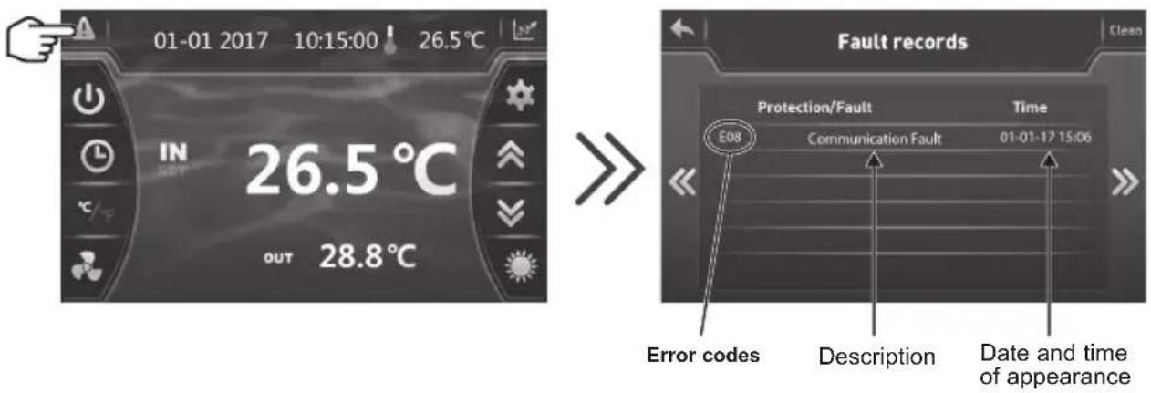
6.4 Troubleshooting guide

Certain operations must be carried out by an authorized technician.
If there is a fault on the heat pump, the symbol 🔍 appears blinking red in the left hand corner of the screen.
Press the symbol 🔒 to access the list of errors.
Refer to following table.
text_image
01-01 2017 10:15:00 26.5°C
IN
26.5 °C
OUT 28.8°C
Fault records
Protection/Fault Time
E08 Communication Fault 01-01-17 15:06
Error codes Description Date and time of appearance

Once the problem has been resolved the error is cancelled automatically and the triangle changes to solid grey.

To delete the error list, press on then return to the previous screen by pressing on
6. APPENDIX (continued)
| Problem | Error codes | Description Solution | |
| Water inlet sensor fault P01 | | The sensor is open or has short-circuited. | Verify the CN21/RES1 connectors on the board and the extension connector or replace the sensor |
| Water outlet sensor fault P02 | | Verify the N22/RES2 connectors on the board and the extension connector or replace the sensor |
| Outside temperature sensor fault P04 | | Verify the CN12/PH connectors on the board and the extension connector or replace the sensor |
| De-icing sensor fault P05 | | Verify the CN8/OPT connectors on the board and the extension connector or replace the sensor |
| Compressor aspiration sensor defect P07 | Verify the CN7/OAT connectors on the board and the extension connector or replace the sensor |
| Compressor discharge sensor fault P081 | Verify the CN9/OHT connectors on the board and the extension connector or replace the sensor |
| High pressure protection E01 The sensor is open or has short-circuited. | Verify the CN30/HP connectors on the card or replace the sensor |
| Check the water flow |
| Check the water flow detector |
| Check the valve opening |
| Check the by-pass |
| Check the evaporator is not clogged |
| Water temperature too hot |
| Incondensable problem after maintenance, empty and evacuate the cooling circuit |
| Fluid load too high, remove fluid into a liquid bottle |
| Low pressure protection E02 The sensor is open or has short-circuited. | Check the AI/DI03 connections on the card or replace the sensor |
| Large coolant leak, search for the leak with the detector |
| Air flow too low, check the ventilator rotation speed |
| Check the evaporator is not clogged, clean its surface |
| Flow sensor fault E03 The sensor is open or has short-circuited. | Check the AI/DI02 connections on the card or replace the sensor |
| Lack of water, check the filtration pump operation |
| Check the stop valve opening |
| Check the by-pass adjustment |
6. APPENDIX (continued)
| Problem | Error codes | Description Solution | |
| Input/Output temperature difference >13°C | E06 | Applicable in Cold mode only | Lack of water, check the filtration pump operation |
| Check the stop valve opening |
| Check the by-pass adjustment |
| Antifreeze protection Cold mode E07 | Water out | put temperature < 4°C | Stop the heat pump, empty the condenser risk of freezing |
| Communication problem E08 | | No communication between the printed circuit board and the user interface | Check the connectors - see the wiring diagram |
| Level 1 antifreeze protection E19 | | 2°< Water temperature < 4°and Air temperature < 0° | Stop heat pump operation, empty the condenser to avoid freezing, by default the heat pump starts the filtration pump to avoid icing over |
| Level 2 antifreeze protection E29 | | Water temperature < 2°and Air temperature < 0° | Stop heat pump operation, empty the condenser to avoid freezing, by default the heat pump starts the filtration pump and the heat pump to avoid icing over. |
| Fan motor fault F031 Motor jammed or faulty connection | Check free rotation; check CN97/DC connectors; replace the motor |
| Fan motor fault F051 Faulty connection | | Check the DCFAN/CN97 connector; replace the motor |
| Exterior temperature too low TP Operating limit reached Stop the heat pump | |
| Pressure sensor fault PP The sensor is open or short-circuiting | Check the connections see electrical diagram |
6. APPENDIX (continued)
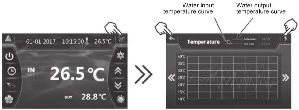
6.5 Recording base
From the main screen, press on 📄 to access the history of water input and output temperature recordings.

This data is available for 60 days.
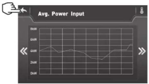
Press on to access the average electric power consumed.
text_image
01-01 2017 10:15:00 26.5°C
IN
SET 26.5°C
OUT 28.8°C
Water input
temperature curve
Water output
temperature curve
Temperature
Outer water 30.5°C
Inner water 30.5°C
40°C
35°C
30°C
25°C
20°C
15°C
10°C
line
Avg. Power Input
| Time Point | Avg. Power Input (kW) |
| :--- | :--- |
| 1 | 4.0 |
| 2 | 4.5 |
| 3 | 3.8 |
| 4 | 4.2 |
| 5 | 3.9 |
| 6 | 3.5 |
| 7 | 2.8 |
| 8 | 2.5 |
| 9 | 3.0 |
| 10 | 3.5 |
| 11 | 4.0 |
| 12 | 4.2 |
| 13 | 4.5 |
| 14 | 4.8 |
| 15 | 5.0 |
| 16 | 5.2 |
| 17 | 5.5 |
| 18 | 5.8 |
| 19 | 6.0 |
| 20 | 6.2 |
| 21 | 6.5 |
| 22 | 6.8 |
| 23 | 7.0 |
| 24 | 7.2 |
| 25 | 7.5 |
| 26 | 7.8 |
| 27 | 8.0 |
| 28 | 8.2 |
| 29 | 8.5 |
| 30 | 8.8 |
| 31 | 9.0 |
| 32 | 9.2 |
| 33 | 9.5 |
| 34 | 9.8 |
| 35 | 10.0 |
| 36 | 10.2 |
| 37 | 10.5 |
| 38 | 10.8 |
| 39 | 11.0 |
| 40 | 11.2 |
| 41 | 11.5 |
| 42 | 11.8 |
| 43 | 12.0 |
| 44 | 12.2 |
| 45 | 12.5 |
| 46 | 12.8 |
| 47 | 13.0 |
| 48 | 13.2 |
| 49 | 13.5 |
| 50 | 13.8 |
| 51 | 14.0 |
| 52 | 14.2 |
| 53 | 14.5 |
| 54 | 14.8 |
| 55 | 15.0 |
| 56 | 15.2 |
| 57 | 15.5 |
| 58 | 15.8 |
| 59 | 16.0 |
| 60 | 16.2 |
| 61 | 16.5 |
| 62 | 16.8 |
| 63 | 17.0 |
| 64 | 17.2 |
| 65 | 17.5 |
| 66 | 17.8 |
| 67 | 18.0 |
| 68 | 18.2 |
| 69 | 18.5 |
| 70 | 18.8 |
| 71 | 19.0 |
| 72 | 19.2 |
| 73 | 19.5 |
| 74 | 19.8 |
| 75 | 20.0 |
| 76 | 20.2 |
| 77 | 20.5 |
| 78 | 20.8 |
| 79 | 21.0 |
| 80 | 21.2 |
| 81 | 21.5 |
| 82 | 21.8 |
| 83 | 22.0 |
| 84 | 22.2 |
| 85 | 22.5 |
| 86 | 22.8 |
| 87 | 23.0 |
| 88 | 23.2 |
| 89 | 23.5 |
| 90 | 23.8 |
| 91 | 24.0 |
| 92 | 24.2 |
| 93 | 24.5 |
| 94 | 24.8 |
| 95 | 25.0 |
| 96 | 25.2 |
| 97 | 25.5 |
| 98 | 25.8 |
| 99 | 26.0 |
| Note: The 'Average Power Input' values are estimated based on the chart title and are not explicitly provided in the code.
Press on to return to the main screen.
6. APPENDIX (continued)
6.6 Warranty
WARRANTY CONDITIONS
All HAYWARD products are guaranteed to be free from manufacturing or material faults for a period of two years as from the date of purchase. Any claim made under the terms of the warranty must be accompanied by a dated proof of purchase. We therefore recommend that you keep your invoice.
The HAYWARD warranty is limited to the repair or replacement, at HAYWARD's discretion, of faulty products, provided they have been used under normal conditions, as described in their user guide, and that the product has not been modified in any way and has been used only with HAYWARD components and parts. Frost and chemical damage are not covered.
No other costs (transportation, labour, etc.) are covered by the warranty.
HAYWARD cannot be held liable for any direct or indirect damage caused by the incorrect installation, connection or operation of a product.
Please contact your retailer if you want to make a claim under the terms of the warranty and request the repair or replacement of an item. No equipment returned to our factory will be accepted without our prior written agreement.
Worn parts are not covered by the warranty.
ENERGYLINE PRO INVERTER
UNIDAD DE BOMBA DE CALOR PARA PISCINAS
natural_image
Exterior view of a Hayward air conditioner unit with fan blades (no visible text or symbols)

text_image
R32
text_image
= = Ⓧ ===
L N ⊕ 1 2
Contacto seco
Alimentación general
230V ∼ / 50Hz
Contacto seco 16 A máx.
libre de potencial
Función prioridad
del calentamiento
text_image
01-01 2017 10:15:00 26.5°C
IN
SET
26.5°C
OUT 28.8°C
2 S
>>
text_image
01-01 2017 10:15:00 ! 26.5°C
IN
SET
26.5°C
OUT 28.8°C
text_image
01-01 2017 10:15:00 26.5°C
IN
26.5 °C
OUT 28.8 °C
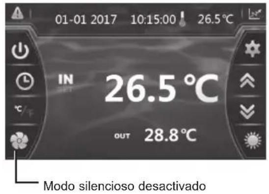
Modo silencioso desactivado
natural_image
Exterior view of a gray industrial water heater with a hand valve and label (no readable text or symbols)
text_image
Technical diagram of an air conditioning unit with numbered components and labeled parts
natural_image
Exterior view of a modern HVAC air conditioning unit with a black fan and control panel (no visible text or symbols on the device itself)

text_image
R32
text_image
= = ≡ ==
L N ⊕ 1 2
Contacto seco
text_image
01-01 2017 10:15:00 ! 26.5°C
IN
SET
26.5°C
OUT 28.8°C

text_image
01-01 2017 10:15:00 ! 26.5°C
IN
26.5 °C
OUT 28.8 °C
Modo silêncio desactivado
Configurar o temporizador

text_image
01-01 2017 10:15:00 26.5°C
IN
OUT 26.5 °C
28.8 °C

text_image
01-01 2017 10:15:00 ! 26.5°C
IN
SET
26.5 °C
OUT 28.8 °C
natural_image
Exterior view of a beige industrial cabinet with a hand valve and a black arrow pointing upward (no visible text or symbols)
text_image
Technical diagram of an air conditioning unit with numbered components and labeled parts
natural_image
Exterior view of a Hayward air conditioner unit with fan blades (no visible text or symbols)

text_image
R32
text_image
01-01 2017 10:15:00 ! 26.5°C
IN
SET
26.5°C
OUT 28.8°C
text_image
01-01 2017 10:15:00 ! 26.5°C
IN
26.5 °C
OUT 28.8 °C
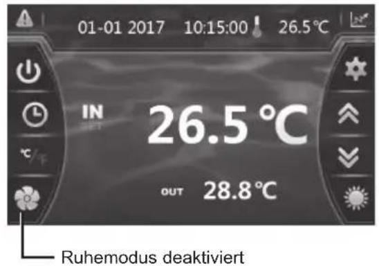
Ruhemodus deaktiviert
natural_image
Exterior view of a gray industrial water heater with a hand valve and label (no readable text or symbols)
text_image
Technical diagram of an air conditioning unit with numbered components and labeled parts
natural_image
Exterior view of a Hayward air conditioner unit with fan blades (no visible text or symbols)

text_image
R32
In Modus "OFF" of "ON"
Handmatige deactivering

text_image
01-01 2017 10:15:00 26.5°C
IN 26.5 °C
OUT 28.8 °C


text_image
01-01 2017 10:15:00 ! 26.5°C
IN
SET
26.5°C
OUT 28.8°C
text_image
01-01 2017 10:15:00 ! 26.5°C
IN
OUT 26.5 °C
28.8 °C
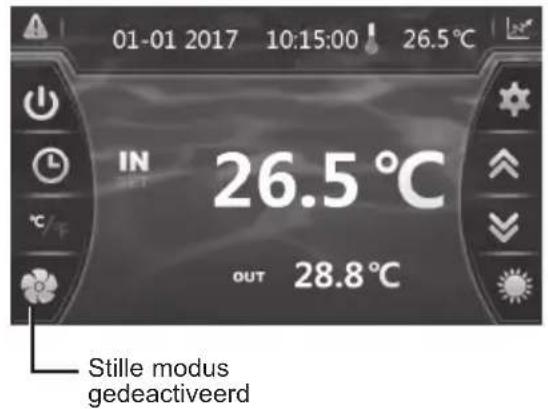
Stille modus
gedeactiveerd
11: BINNENKOMEND WATER
LP : LAGEDRUKSCHAKELAAR
TEMPERATUURSENSOR VOOR
BUITENGAAND WATER
SUT : AANZUIGTEMPERATUURSENSOR
K2 : VOLTVRIJ CONTACT MAX 16 A
ET : TEMPERATUURSENSOR OPSTUWING
PS: DRUKSENSOR
11: BINNENKOMEND WATER
LP : LAGEDRUKSCHAKELAAR
TEMPERATUURSENSOR VOOR
BUITENGAAND WATER
SUT : AANZUIGTEMPERATUURSENSOR
K2 : VOLTVRIJ CONTACT MAX 16 A
ET : TEMPERATUURSENSOR OPSTUWING
PS : DRUKSENSOR
natural_image
Exterior view of a beige industrial cabinet with a hand valve and a black arrow pointing upward (no visible text or symbols)
text_image
Technical diagram of an air conditioning unit with numbered components and labeled parts
natural_image
Exterior view of a modern HVAC air conditioning unit with a black fan and control panel (no visible text or symbols on the device itself)

text_image
R32
text_image
01-01 2017 10:15:00 ! 26.5°C
IN
SET
26.5°C
OUT 28.8°C
natural_image
Exterior view of a beige industrial cabinet with a black upward arrow and label (no readable text or symbols)
text_image
Technical diagram of an air conditioning unit with numbered components and labeled parts
6. APPENDICI (segue)
ENPI4M / ENPI6M
| Num. | Designazione Rif. ENPI4M ENPI6M | | | |
| 1 Valvola 4 vie HWX20041437 | | √ | √ |
| 2 R | iduttore di pressione elettronico | HWX81000015 | √ | n/a |
| HWX81000016 n/a | | √ |
| 3 F | Filtro ø9.7-ø9.7 (∅28) HWX20041444 | | √ | √ |
| 4 R | Rilevatore portata acqua HWX83000012 | | √ | √ |
| 5 C | Connettore a T ø9.52-2 x ø6.5(T) x 1.0 HWX304030000002 | | √ | √ |
| 6 P | Portello d'accesso scatola elettrica HWX320922029 | | √ | √ |
| 7 P | Pannello destro HWX80700455 | | √ | √ |
| 8 P | Pannello decorativo destro HWX80900089 | | √ | √ |
| 9 C | Condensatore Titanio/PVC | HWX80600074 | √ | n/a |
| HWX80600096 n/a | | √ |
| 10 Compressore | HWX20000110448 | √ | n/a |
| HWX80100003 n/a | | √ |
| 11 / | / | / | / |
| 12 / | / | / | / |
| 13 Morsettiera L-N-GND -5 connessioni 4mm2 | HWX40003901 | √ | √ |
| 14 Logo HAYWARD | HWX20000230596 | √ | √ |
| 15 Touch screen a colori | HWX95005310612 | √ | √ |
| 16 / | / | / | / |
| 17 Griglia di protezione ventilatore | HWX20000220169 | √ | √ |
| 18 Elica ventilatore | HWX20000270004 | √ | √ |
| 19 Motore ventola DC | HWX20000330132 | √ | √ |
| 20 Pannello decorativo sinistro | HWX80900088 | √ | √ |
| 21 Pannello anteriore | HWX80900087 | √ | √ |
| 22 supporto motore | HWX80700248 | √ | √ |
| 23 Evaporatore a piastre | HWX80600044 | √ | n/a |
| HWX80600100 n/a | | √ |
| 24 Pannello sinistro | HWX80700455 | √ | √ |
| 25 / | / | / | / |
| 26 Pannello superiore | HWX301090200806 | √ | √ |
| 27 Scheda elettronica Driver | HWX82300008 | √ | n/a |
| HWX82300007 n/a | | √ |
| 28 Trasformatore 230V~/12VDC | HWX82600008 | √ | √ |
| 29 / | / | / | / |
| 30 Relè K2 | HWX20000360297 | √ | √ |
| 31 Bobina 20A 50Hz 5mH | HWX82500005 | √ | √ |
| 32 Pressostato Bassa pressione NO 0.30MPa/0.15MPa | HWX20000360157 | √ | √ |
| 33 Rilevamento Pressione 40mm 1/2" | HWX20000140150 | √ | √ |
| 34 Pressostato Alta pressione NC 3.2MPa/4.4MPa | HWX20013605 | √ | √ |
| 35 Connecteur T ø6.5-2 x ø6.5(T) x 0.75T2M | HWX20001460 | √ | √ |
| 36 / | / | / | / |
| 37 Sensore di Pressione | HWX20000360123 | √ | √ |
| 38 Sonda scarico compressore 50 kΩ-660mm | HWX83000026 | √ | √ |
| 39 Sonda temperatura aria 5k-350mm | HWX83000049 | √ | √ |
| Sonda uscita acqua 5k-410mm | √ | √ |
| Sonda temperatura acqua in ingresso 5k-850mm | HWX83000052 | √ |
| Sonda di aspirazione compressore 5k-560mm | HWX83000044 | √ |
| Sonda antigelo 5k-680mm | HWX83000051 | √ |
| 40 Filtro EMC | HWX20003257 n/a | | √ |
6. APPENDICI (segue)
natural_image
Exterior view of a modern HVAC air conditioning unit with a black fan and control panel (no visible text or symbols on the device itself)

text_image
R32
5. VEDLIKEHOLD OG VINTERKLARGJ∅RING 21
(1) Global warming potential (GWP))
2. SPESIFIKASJONER
2.1 Varmepumpens ytelse
| Modeller | ENERGYLINE PRO INVERTER | ENPI4M ENPI6M | |
| Tilførselsspenning V | | 220V-240V ^ / 1ph / 50Hz |
| Kuldemedium / R32 | | |
| Last kg 0,50 0,65 | | | |
| Masse i teqCO2 | / 0,34 0,44 | | |
| Hyppighet for lekkasjekontroll / Er ikke påkrevet, men årlig kontroll anbefales |
| Oppvarmingskapasitet Min--Maks (a) kW 2,50--9,73 3,20--11,9 | | | |
| Absorbert elektrisk effekt Min--Maks (a) | kW 0,20--1,34 | 0,28--1,68 | |
| Nominell strømverdi Min--Maks (a) | A 1,33--6,02 | 1,34--7,32 | |
| COP Maks--Min (a) | / | 12,32--7,12 | 11,51--7,10 |
| Oppvarmingskapasitet Min--Maks (b) kW 1,71--7,60 2,70--9,70 | | | |
| Absorbert elektrisk effekt Min--Maks (b) | kW 0,27--1,49 | 0,44--1,88 | |
| COP Maks--Min (b) | / | 6,40--5,1 | 6,10--5,55 |
| Maksimum strømverdi | A | 7,30 8,90 | |
| Sikringsstørrelse | aM | 8 | 10 |
| Effektbryter Kurve D | D | 8 | 10 |
| Startstrøm | A | < Maksimum strømverdi | < Maksimum strømverdi |
| Hydraulisk tilkopling | mm | 50mm |
| Nominell vannstrøm (a) | m3/h | 4,20 5,10 | |
| Fall i vantrykk (maks.) | kPa | 3,3 | 4,5 |
| Kompressor | / | Mitsubishi DC-omformer | Highly DC-omformer |
| Type | / Dobbeltroterende | Dobbeltroterende |
| Antall | / | 1 |
| Svingningsmotstand ved 20°C | Ohm | 1,91 | 0,788 |
| Vifte | / | Axial |
| Antall | | 1 |
| Diameter | mm | 405 510 | |
| Antall rotor | / | 3 |
| Motor | / | DC-omformer |
| Antall | / | 1 | 1 |
| Rotasjonshastighet | Omdr/min | 500--700 | 500-650 |
| Hastighet i Silent Mode | Omdr/min 300 | 400 | |
| Lydtrykknivå ved 1 m | dB(A) | 33--41 | 33-41 |
| Lydtrykknivå ved 10 m | dB(A) | 16--25 | 16--25 |
| Enhetens dimensjoner, netto (L-I-H) | mm | 1046/400/768 |
| Vekt | kg 53 | 65 | |
2. SPESIFIKASJONER (fortsetter)
2.2 Driftsområde
2. SPESIFIKASJONER (fortsetter)
2.3 Dimensjoner
Modeller:
ENPI4M / ENPI6M
3. INSTALLERING OG TILKOBLING (fortsetter)

3. INSTALLERING OG TILKOBLING (fortsetter)
3.4 Elektrisk tilkobling

3. INSTALLERING OG TILKOBLING (fortsetter)

Strømledningen skal være utstyrt med en sikring av typen aM eller en effektbryter Kurve D, samt en 30mA jordfeilbryter (se tabell nedenfor).
| Modeller ENPI4M ENPI6M | | |
| Elektrisk strømforsyning | V/Ph/Hz | 230V 50Hz | 230V 50Hz |
| Sikringsstørrelse av typen aM A 8 aM | 10 aM | | |
| Effektbryter Kurve D A 8 D 10 D | | | |
| Kabelseksjon | mm ^2 | 3G 2,5 3G 2,5 | |

Bruk en kabel av typen RO 2V / R 2V eller tilsvarende.

3. INSTALLERING OG TILKOBLING (fortsetter)
3. INSTALLERING OG TILKOBLING (fortsetter)
4. BRUKERGRENSESNITT (fortsetter)
OFF-modus
Når varmepumpen er i standby (OFF-modus) knappen ledtonet.
ON-modus
Når varmepumpen er i drift eller under innstilling (ON-modus) knappen lyser grønt.

4. BRUKERGRENSESNITT (fortsetter)
text_image
01-01 2017 10:15:00 26.5°C
IN
OUT 26.5°C
OUT 28.8°C


text_image
Timer
2
text_image
Time switch
ON
OFF
00:00


text_image
Time switch
12
1 2 3
5 6
8 9
0
12:00
00:00
Godkjenne
text_image
Time switch
6
Aktiver

text_image
Time switch
12:00
00:00

Blå marking = Aktivert
Nedtonet = Deaktivert

4. BRUKERGRENSESNITT (fortsetter)
4. BRUKERGRENSESNITT (fortsetter)
text_image
01-01 2017 10:15:00 26.5°C
IN
SET
26.5°C
OUT 28.8°C
1
2 S
>>
4. BRUKERGRENSESNITT (fortsetter)
4. BRUKERGRENSESNITT (fortsetter)
Manuell deaktivering

text_image
01-01 2017 10:15:00 26.5°C
IN 26.5 °C
OUT 28.8 °C


text_image
01-01 2017 10:15:00 ! 26.5°C
IN
SET
26.5°C
OUT 28.8°C
text_image
01-01 2017 10:15:00 ! 26.5°C
IN
26.5 °C
OUT 28.8 °C
Silence-modus er deaktivert
4. BRUKERGRENSESNITT (fortsetter)
6. VEDLEGG (fortsetter)
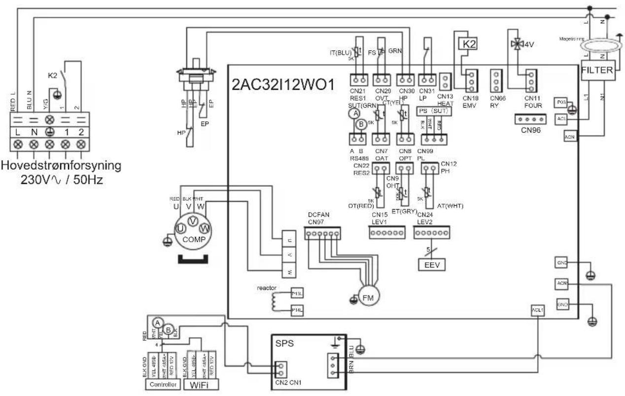
ENPI6M
text_image
Hovedstrømforsyning
230V~ / 50Hz
RED L
BLU N
YIG
L
N
1
2
K2
EP
HP
EP
HP
IT(BLU)
SX
FS
GRN
CN21
RES1
SUT(GRN)
CN29
OVT
CT(YE)
CN30
HP
CN31
LP
CN13
HEAT
PS (SUT)
B.X.
B.K.
CN18
EMV
CN66
RY
CN11
FOUR
CN96
FILTER
L1
N1
Z
A B
RS485
CN22
RES2
CN7
OAT
CN8
OPT
CN99
PL
CN12
PH
OT(RED)
EN
ET(GRY)
5K
AT(WHT)
DCFAN
CN97
CN15
LEV1
CN24
LEV2
5
EEV
FM
reactor
P1L
P14L
SPS
CN2 CN1
BRN FLU
ELK OND
WHT 485A-
RED 48V-
ELK OND
WHT 485A-
RED 48V-
Controller
WiFi
MERKNADER
AT : SENSOR FOR LUFTTEMPERATUR
LP: LAVTRYKKSBRYTER
COMP : KOMPRESSOR OT : TEMPERATURSENSOR TIL VANNUTL∅P
CT : SENSOR FOR FORDAMPET TEMPERATUR SUT : SENSOR FOR SUGETEMPERATUR
EEV : ELEKTRONISK EKSPANSJONSVENTIL
4V : 4-VEIS VENTIL
FM : VIFTEMOTOR K2 : POTENSIALFRI KONTAKT, MAKS. 16A
FS : VANNSENSOR
ET : TEMPERATURSENSOR FOR UTLADNING
HP : H∅YTRYKKSBRYTER PS : TRYKKSENSOR
IT : TEMPERATURSENSOR TIL VANNINNL∅P
6. VEDLEGG (fortsetter)
6.2 Kobling med prioritet på enfaset varmepumpe
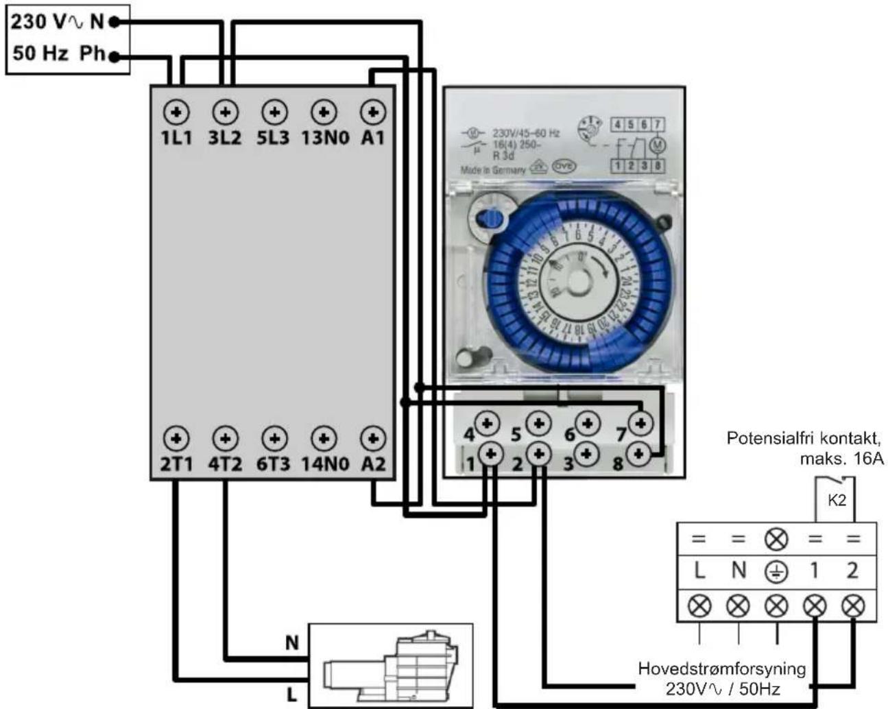
text_image
230 V N
50 Hz Ph
1L1 3L2 5L3 13N0 A1
230V/45-60 Hz
16(4) 250-
R 3d
Made in Germany
4 5 6 7
μ
F 7 M
1 2 3 8
4 5 6 7 6 5 4 3 1
1 2 3 8
Potensialfri kontakt,
maks. 16A
K2
= = = =
L N ÷ 1 2
Hovedstrømforsyning
230V√ / 50Hz
natural_image
Exterior view of a gray industrial water heater with a hand valve and label (no readable text or symbols)
6. VEDLEGG (fortsetter)
text_image
Technical diagram of an air conditioning unit with numbered components and labeled parts
ENPI4M / ENPI6M
| Nr. | Betegnelse Ref. ENPI4M ENPI6M | | | |
| 1 | 4-veisventil HWX20041437 | | √ | √ |
| 2 | Elektronisk ekspansjonsventil | HWX81000015 | √ | Gjelder ikke |
| HWX81000016 Gjelder ikke | √ |
| 3 | Filter ø9.7-ø9.7 (∅28) HWX20041444 | | √ | √ |
| 4 | Sensor for vannstrømning HWX83000012 | | √ | √ |
| 5 | T-formet connector ø9.52-2 x ø6.5(T) x 1.0 HWX304030000002 | √ | √ |
| 6 | Trappe elektrisk tilgang HWX320922029 | | √ | √ |
| 7 | Høyre panel HWX80700455 | | √ | √ |
| 8 | Høyre dekorpanel HWX80900089 | | √ | √ |
| 9 | Kondensator Titanium/PVC | HWX80600074 | √ | Gjelder ikke |
| HWX80600096 Gjelder ikke | √ |
| 10 | Kompressor | HWX20000110448 | √ | Gjelder ikke |
| HWX80100003 Gjelder ikke | √ |
| 11 | / | / | / | / |
| 12 | / | / | / | / |
| 13 | Terminal L-N-GND -5 tilkoplinger 4mm ^2 | HWX40003901 | √ | √ |
| 14 | HAYWARD-logo | HWX20000230596 | √ | √ |
| 15 | Berøringsskjerm med farger | HWX95005310612 | √ | √ |
| 16 | / | / | / | / |
| 17 | Beskyttelsesgitter for viften | HWX20000220169 | √ | √ |
| 18 | Vifteproprell | HWX20000270004 | √ | √ |
| 19 | Viftemotor DC | HWX20000330132 | √ | √ |
| 20 | Venstre dekorpanel | HWX80900088 | √ | √ |
| 21 | Fremre panel | HWX80900087 | √ | √ |
| 22 | Motorstøtte | HWX80700248 | √ | √ |
| 23 | Vinget fordamper | HWX80600044 | √ | Gjelder ikke |
| HWX80600100 Gjelder ikke | √ |
| 24 | Venstre panel | HWX80700455 | √ | √ |
| 25 | / | / | / | / |
| 26 | Øvre panel | HWX301090200806 | √ | √ |
| 27 | Elektronisk Driver-kort | HWX82300008 | √ | Gjelder ikke |
| HWX82300007 Gjelder ikke | √ |
| 28 | Transformer 230V~/12VDC | HWX82600008 | √ | √ |
| 29 | / | / | / | / |
| 30 | Relé K2 | HWX20000360297 | √ | √ |
| 31 | Spole 20A 50Hz 5mH | HWX82500005 | √ | √ |
| 32 | Strømningsbegrenser NO 0.30MPa/0.15MPa | HWX20000360157 | √ | √ |
| 33 | Trykktilkobling 40mm, 1/2" | HWX20000140150 | √ | √ |
| 34 | Høytrykkspressostat NC 3.2MPa/4.4MPa | HWX20013605 | √ | √ |
| 35 | T-formet connector ø6.5-2 x ø6.5(T) x 0.75T2M | HWX20001460 | √ | √ |
| 36 | / | / | / | / |
| 37 | Trykksensor | HWX20000360123 | √ | √ |
| 38 | Kompressorutladningssonde 50 kΩ-660mm | HWX83000026 | √ | √ |
| 39 | Lufttemperatur probe 5k-350mm | HWX83000049 | √ | √ |
| Vannuttak probe 5k-410mm | HWX83000050 | √ | √ |
| Vanninntak probe 5k-850mm | HWX83000052 | √ | √ |
| Kompressorsugesonde 5k-560mm | HWX83000044 | √ | √ |
| Avrimings sensor 5k-680mm | HWX83000051 | √ | √ |
| 40 | EMC Filter | HWX20003257 Gjelder ikke | √ |
6. VEDLEGG (fortsetter)
6. VEDLEGG (fortsetter)
6. VEDLEGG (fortsetter)
6. VEDLEGG (fortsetter)
6.5 Lagringsbase
6. VEDLEGG (fortsetter)
6.6 Garanti
GARANTIBETINGELSER
natural_image
Exterior view of a modern HVAC air conditioning unit with a black fan and control panel (no visible text or symbols on the device itself)

text_image
R32
text_image
01-01 2017 10:15:00 26.5°C
IN
SET
26.5°C
OUT 28.8°C
1
2 s
>>
natural_image
Exterior view of a gray industrial water heater with a hand valve and label (no readable text or symbols)
text_image
Technical diagram of an air conditioning unit with numbered components and labeled parts
natural_image
Simple line drawing of a trash bin with two crossed lines and a blank rectangular base (no text or symbols)