HSBC 300 cool - Boiler STIEBEL ELTRON - Free user manual and instructions
Find the device manual for free HSBC 300 cool STIEBEL ELTRON in PDF.
| Brand | Stiebel Eltron |
| Model | HSBC 300 cool |
| Product type | Boiler with buffer tank and domestic hot water tank |
| Dimensions (H × W × D) | 1918 × 680 × 910 mm |
| Empty weight | 250 kg |
| Weight in operation (filled) | 641 kg |
| Power supply | 230 V / 1/N/PE / 50 Hz |
| Electrical protection control | 1 × B 16 A |
| Max. electrical power consumption (pumps) | 60 W each |
| Domestic hot water tank capacity | 270 L |
| Buffer tank capacity | 100 L |
| Max. admissible pressure DHW tank | 1.00 MPa (10 bar) |
| Max. admissible pressure buffer tank | 0.30 MPa (3 bar) |
| Max. admissible temperature (DHW) | 85 °C |
| Max. temperature primary side | 75 °C |
| Energy efficiency class | B |
| Protection rating (IP) | IP20 |
| Main functions | Heating, cooling (7 °C/12 °C), domestic hot water production |
| Maintenance and cleaning | Clean with a damp cloth; have the electrical safety and safety group checked regularly by an installer |
| Safety | Frost protection, safety valve, anode wear indicator |
| Spare parts and repairability | Accessories: HSBC 3-HKM hydraulic kit, RBS-SBC tube kit, temperature sensor, FET remote control |
Frequently Asked Questions - HSBC 300 cool STIEBEL ELTRON
User questions about HSBC 300 cool STIEBEL ELTRON
0 question about this device. Answer the ones you know or ask your own.
Ask a new question about this device
Download the instructions for your Boiler in PDF format for free! Find your manual HSBC 300 cool - STIEBEL ELTRON and take your electronic device back in hand. On this page are published all the documents necessary for the use of your device. HSBC 300 cool by STIEBEL ELTRON.
USER MANUAL HSBC 300 cool STIEBEL ELTRON
BEDIENUNG UND INSTALLATION OPERATION AND INSTALLATION UTILISATION ET INSTALLATION BEDIENING EN INSTALLATIE USO E INSTALLAZIONE
Integralspeicher | Integral cylinder | Tour hydraulique combinée | Combiboiler | Caldaia integrale
» HSBC 300 cool (WPM)
natural_image
Line drawing of a rectangular electronic device with mounting holes and a central button (no text or symbols)STIEBEL ELTRON
BESONDERE HINWEISE
BEDIENUNG
text_image
Technical diagram of an electrical enclosure with labeled components and a magnified inset showing two lock mechanisms.text_image
D0000102540 Made in GermanyINSTALLATION
7. Sicherheit
natural_image
Diagram showing a ball rolling down an object with a rotating screw inside, and a magnified view of the ball's motion (no text or symbols)natural_image
Technical line drawing of a rectangular electronic device with a directional arrow indicating flow or movement (no text or symbols present)text_image
Exploded view diagram of an electrical enclosure with labeled components including casing, panel, and air duct systemD0000101865
1 Dämmelement 1
2 Dämmelement 2
3 Dämmstoffschraube
4 Dämmelement 3
text_image
Technical diagram of an electrical cabinet with labeled components and directional arrows indicating assembly or connection.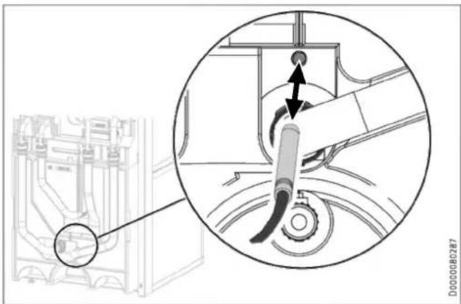
natural_image
Technical diagram showing a mechanical assembly with a magnified inset highlighting a component (no text or symbols present)natural_image
Technical line drawing of a mechanical or electrical enclosure with pipes and components (no text or symbols)text_image
Technical diagram showing a device rear panel with labeled ports and an inset close-up of the handle, plus a 3D geometric triangle view.
natural_image
Cross-sectional diagram of a mechanical assembly with internal components and directional arrows (no text or symbols)natural_image
Technical diagram of a mechanical assembly with pipes and control panel (no text or symbols)natural_image
Technical diagram of an internal device with labeled ports and connectors (no readable text or symbols)natural_image
Technical line drawing of an industrial machine or control unit with multiple ports and mounting brackets (no text or symbols visible)natural_image
3D diagram of a mechanical component with a left-pointing arrow, no text or symbols presentnatural_image
Technical diagram of an electronic device showing internal components and a base housing (no text or symbols present)natural_image
Technical line drawing of an internal electronic device with visible components and wiring (no text or symbols)text_image
Technical diagram of an electronic device with labeled components and a magnified inset showing internal structure details.natural_image
Technical line drawing of a mechanical component with curved and flat surfaces (no text or symbols)natural_image
3D diagram of a mechanical component with a black arrow indicating direction, no text or symbols presenttext_image
Technical diagram of a wall-mounted air conditioner unit with numbered components and labeled partstext_image
Technical diagram of an electronic device with numbered components and a highlighted internal componenttext_image
Technical diagram illustrating mechanical assembly steps with labeled components and warning indicatorstext_image
Technical diagram of an electronic device floor plan with labeled components and connection paths
Sachschaden
natural_image
Technical line drawing of a mechanical assembly with an inset close-up showing a circular component detail (no text or symbols)text_image
Technical diagram of an electrical switchgear assembly with labeled components and a circular cross-section view.natural_image
Technical line drawing of an electronic device showing internal components and mounting brackets (no text or symbols)text_image
Z P E Z P E Z P E Z P 5 X2.4 X2.3 X2.2 X2.1 D0000102047natural_image
Technical line drawing of a mechanical assembly with pipes and housing (no text or symbols)natural_image
Technical line drawing of a mechanical assembly with an inset close-up showing internal components (no text or symbols)natural_image
Technical line drawing of a dual air conditioning unit with fan and cooling unit (no text or symbols)D0000080569
- General information 33
1.1 Relevant documents 33
1.2 Safety instructions 33
1.3 Other symbols in this documentation 34
1.4 Information on the appliance 34
1.5 Units of measurement 34 - Safety 34
2.1 Intended use 34
2.2 General safety instructions 34
2.3 Test symbols 34 - Appliance compatibility 35
- Appliance description 35
- Cleaning, care and maintenance 35
- Troubleshooting 35
INSTALLATION
- Safety 36
7.1 General safety instructions 36
7.2 Instructions, standards and regulations 36 - Appliance description 36
8.1 Standard delivery 36
8.2 Accessories 36 - Preparation 36
9.1 Installation site 36
9.2 Transport and handling 37 - Installation 42
10.1 Positioning the appliance 42
10.2 Heating water connection 42
10.3 DHW connection and safety assembly 44
10.4 Filling the system 45
10.5 Venting the appliance 46 - Electrical connection 46
11.1 Control voltage 47
11.2 Safety extra low voltage 47
11.3 Heat pump manager terminal assignment 47
11.4 Accessories 48
11.5 Sensor installation 49
11.6 Remote control 49 - Commissioning 49
12.1 Checks before commissioning the heat pump manager 49
12.2 Commissioning the heat pump manager ____ 49 - Settings 50
13.1 Wilo-Para .../Sc circulation pumps 50 - Appliance handover 51
- Shutting down the system 51
- Maintenance 51
- Specification 52
17.1 Dimensions and connections 52
17.2 Wiring diagram 54
17.3 Sample installation 57
17.4 Energy consumption data 57
17.5 Data table 57
GUARANTEE
ENVIRONMENT AND RECYCLING
SPECIAL INFORMATION
- The appliance may be used by children over 8 years of age and persons with reduced physical, sensory or mental capabilities or a lack of experience and expertise, provided that they are supervised or they have been instructed on how to use the appliance safely and have understood the potential risks. Children must never play with the appliance. Cleaning and user maintenance must not be carried out by children without supervision.
- The connection to the power supply must be in the form of a permanent connection. Install a safety device to enable the unit to be separated from the power supply over an isolating distance of 3 mm. Safety devices include, for example, contactors, circuit breakers, fuses/MCBs.
- Observe all applicable national and regional regulations and instructions.
- Observe minimum distances (see chapter "Installation / Preparations / Installation site").
- Only a qualified contractor should carry out installation, commissioning, maintenance and repair of the appliance.
DHW cylinder
- Drain the appliance as described in chapter "Installation / Maintenance / Draining the DHW cylinder".
- Observe the maximum permissible pressure (see chapter "Installation / Specification / Data table").
- The DHW cylinder is under supply pressure. During the heat-up process, expansion water will drip from the safety valve.
- The safety valve drain aperture must remain open to atmosphere.
OPERATION
1. General information
The chapters "Special information" and "Operation" are intended for appliance users and qualified contractors.
The chapter "Installation" is intended for qualified contractors.

Note
Read these instructions carefully before using the appliance and retain them for future reference.
Pass on these instructions to a new user if required.
1.1 Relevant documents
Instructions for the WPM heat pump manager
Operating and installation instructions for the connected heat pump
Operating and installation instructions for all other system components
1.2 Safety instructions
1.2.1 Structure of safety instructions

KEYWORD Type of risk
Here, possible consequences are listed that may result from failure to observe the safety instructions.
▶ Steps to prevent the risk are listed.
1.2.2 Symbols, type of risk
| Symbol | Type of risk | |
 | Injury | |
 | Electrocution | |
 | Burns(burns, scalding) | |
1.2.3 Keywords
| KEYWORD | Meaning |
| DANGER | Failure to observe this information will result in serious injury or death. |
| WARNING | Failure to observe this information may result in serious injury or death. |
| CAUTION | Failure to observe this information may result in non-serious or minor injury. |
1.3 Other symbols in this documentation

Note
General information is identified by the adjacent symbol.
▶ Read these texts carefully.
Symbol
Meaning

Material losses
| (appliance damage, consequential losses and environmental pollution) |

Appliance disposal
This symbol indicates that you have to do something. The action you need to take is described step by step.
1.4 Information on the appliance
Connections
| Symbol | Meaning | ||
| Inlet / intake | Red arrow: hotBlue arrow: ColdGreen arrow: Neutral | ||
| Drain / outlet | Red arrow: hotBlue arrow: ColdGreen arrow: Neutral | ||
 | Domestic hot water | ||
 | DHW circulation | ||
 | Heat pump | ||
 | Heating | ||
1.5 Units of measurement

Note
All measurements are given in mm unless stated otherwise.
2. Safety
2.1 Intended use
This appliance is intended to be used for seasonal heating and cooling of interiors (7 °C / 12 °C) and for DHW heating.
The appliance is intended for domestic use. It can be used safely by untrained persons. The appliance can also be used in non-domestic environments, e.g. in small businesses, as long as it is used in the same way.
Any other use beyond that described shall be deemed inappropriate. Observation of these instructions and of the instructions for any accessories used is also part of the correct use of this appliance.
2.2 General safety instructions

WARNING Burns
There is a risk of scalding at outlet temperatures in excess of 43 °C.

WARNING Injury
The appliance may be used by children over 8 years of age and persons with reduced physical, sensory or mental capabilities or a lack of experience and expertise, provided that they are supervised or they have been instructed on how to use the appliance safely and have understood the potential risks. Children must never play with the appliance. Cleaning and user maintenance must not be carried out by children without supervision.

WARNING Injury
For safety reasons, only operate the appliance with the front casing closed.

Material losses
The system's active frost protection is not guaranteed if the power supply is interrupted.
▶ Never interrupt the power supply even outside the heating season.

Note
The DHW cylinder is under supply pressure. During the heat-up process, expansion water will drip from the safety valve.
▶ If water continues to drip when heating is completed, please inform your qualified contractor.
2.3 Test symbols
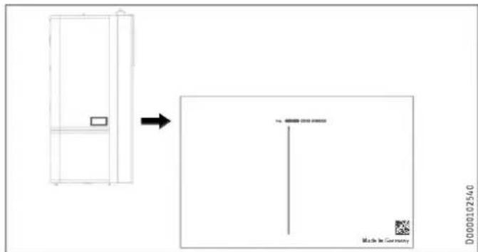
See type plate on the appliance.
3. Appliance compatibility
The appliance can be operated in conjunction with the following air source heat pumps:
- HPA-O 05.1-07.1 CS Premium
- HPA-O 7-13 (C)(S) Premium
- WPL-A 05-07 HK 230 Premium
- WPL 15-25 A(C)(S)
- WPL 19-24 I, A
4. Appliance description
The buffer cylinder and DHW cylinder with indirect coil are arranged one above the other and can be separated for easier handling.
The appliance has a plastic jacket with foam insulation and is equipped with a removable front casing. The appliance is connected hydraulically and electrically to the heat pump. All hydraulic connections are made at the top (heating) and rear (DHW).
In addition to the DHW cylinder and the buffer cylinder, further system components are integrated:
- Heat pump manager
- Highly efficient circulation pump for a heating circuit without mixer
- 3/2-way diverter valve
- Cylinder primary pump
DHW cylinder
The steel cylinder is coated on the inside with special direct enamel and is equipped with a signal anode. The anode with consumption indicator protects the cylinder interior from corrosion.
The heating water heated by the heat pump is pumped through an indirect coil inside the DHW cylinder. The heat channelled through the indirect coil is thus transferred to the domestic hot water. The integral heat pump manager regulates the DHW heating to the required temperature.
Buffer cylinder
The steel cylinder provides hydraulic separation between the flow rates of heat pump and heating circuit. The heating water heated by the heat pump is transferred into the buffer cylinder by the cylinder charging pump. When a demand is issued, the integral heating circuit pump delivers the heating water to the heating circuit.
Heat pump manager (WPM)
The system is controlled by means of the integral heat pump manager.

Note
The heat pump manager has an automatic summer/winter changeover so you can leave the system switched on in summer.
▶ Please observe the instructions for the heat pump manager.
5. Cleaning, care and maintenance
▶ Have the electrical safety of the appliance and the function of the safety assembly regularly checked by a qualified contractor.
▶ Never use abrasive or corrosive cleaning agents. A damp cloth is sufficient for cleaning the unit.
Signal anode with consumption indicator

Material losses
If the consumption indicator changes colour from white to red, have the signal anode checked by a qualified contractor and if necessary replaced.
text_image
Technical diagram of an electrical enclosure with labeled components and a magnified inset showing internal components.1 White = Anode OK
2 Red = Requires checking by qualified contractor
6. Troubleshooting
| Problem | Cause | Remedy |
| The water does not heat up. The heating does not work. | There is no power. | Check the fuses / MCBs in your fuse box / distribution board. |
If you cannot remedy the fault, contact your qualified contractor. To facilitate and speed up your enquiry, please provide the serial number from the type plate (000000-0000-000000).
text_image
D0000102540 Made in GermanyINSTALLATION
7. Safety
Only a qualified contractor should carry out installation, commissioning, maintenance and repair of the appliance.
7.1 General safety instructions
We guarantee trouble-free function and operational reliability only if original accessories and spare parts intended for the unit are used.
7.2 Instructions, standards and regulations

Note
Observe all applicable national and regional regulations and instructions.
8. Appliance description
8.1 Standard delivery
The following are delivered with the appliance:
- 4x Adjustable foot
- 1x Outside temperature sensor AF PT
8.2 Accessories
8.2.1 Required accessories
Safety assemblies and pressure reducing valves are available to suit the prevailing supply pressure. These type-tested safety assemblies protect the appliance against impermissible excess pressure.
Required for area cooling:
- Pt1000 temperature sensor
- FET remote control
8.2.2 Additional accessories
- Pump assembly for a heating circuit with mixer HSBC 3-HKM
- Pipe assembly RBS-SBC
- Pressure hoses
- Water softening fitting HZEA
- Temperature sensor for cooling
- Remote control for heating operation
- STB-FB high limit safety cut-out for underfloor heating systems
Pipe assembly RBS-SBC
The hydraulic connections can be routed upwards at the rear of the DHW cylinder using the RBS-SBC pipe assembly available as an accessory.
9. Preparation
9.1 Installation site

Material losses
Never install the appliance in wet rooms.
Install the appliance near the draw-off point in a dry room free from the risk of frost. To reduce line losses, keep the distance short between the appliance and the heat pump.
Ensure the floor has sufficient load bearing capacity and evenness (for weight, see chapter "Specification / Data table").
The room must not be subject to a risk of explosions arising from dust, gases or vapours.
If you are installing the appliance in a boiler room together with other heating equipment, ensure that the operation of the other heating equipment will not be impaired.
Minimum clearances
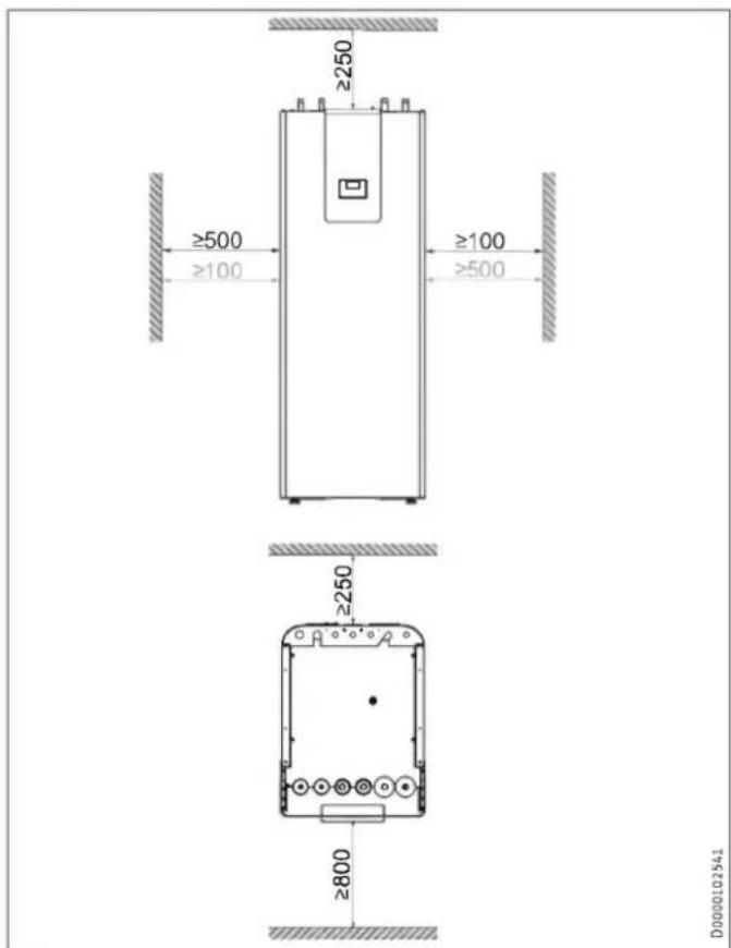
text_image
≥250 ≥500 ≥100 ≥100 ≥500 ≥250 ≥800 D0000102341The minimum side clearances can be swapped between left and right.
9.2 Transport and handling

Material losses
Store and transport the appliance at temperatures between -20 °C and +60 °C.
Handling
▶ Undo the 4 screws from the non-returnable pallet.
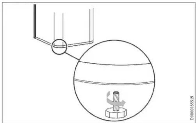
natural_image
Diagram showing a mechanical setup with a rotating component and a magnified view of a bolt inside a spherical housing (no text or symbols)▶ Tilt the appliance and screw the 4 adjustable feet into the appliance.
▶ Lift the appliance off the pallet. For a better hold during transport, use the recessed grips on the underside and rear of the appliance.
If narrow doors or hallways hinder handling, you can separate the upper and lower sections of the appliance as described in the following chapters.
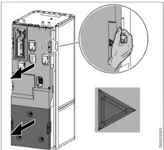
9.2.1 Removing/fitting the front casing
Removing the front casing
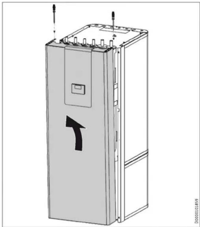
natural_image
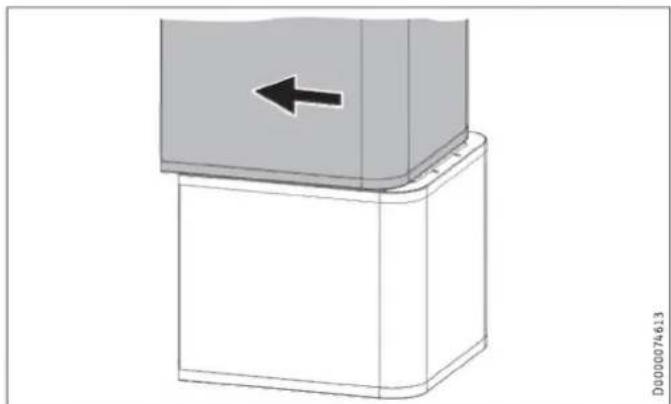
Technical line drawing of a rectangular electronic device with a directional arrow indicator (no text or symbols present)▶ Remove the 2 locking screws on the top of the front casing.
▶ Unhook the front casing towards the top.
▶ AA01-X1.18: If required, disconnect the connector plug of the programming unit from the connection in the appliance. The functionality of the appliance will not be affected. However, it will not be possible to operate the appliance via the programming unit.
▶ Remove the earth cable from the front casing.
Fitting the front casing
▶ Fit the front casing in reverse order.
9.2.2 Overview of insulation segments
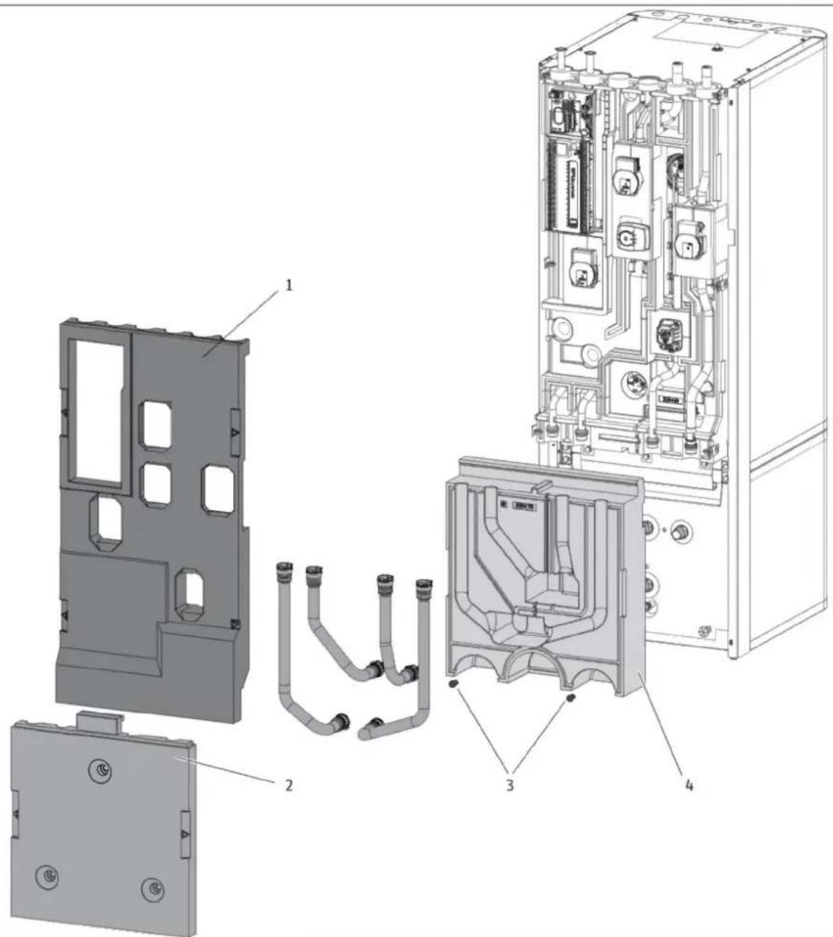
text_image
Exploded view diagram of an industrial electrical enclosure with labeled componentsD0000101865
1 Insulation segment 1
2 Insulation segment 2
3 Insulation material screw
4 Insulation segment 3
9.2.3 Separating / joining the appliance sections
Separating the appliance sections

Material losses
Unscrewing the fastening screws destroys the threads in the insulation segment.
▶ To open the 3 fixing tabs, loosen the fastening screws slightly but do not unscrew them completely.
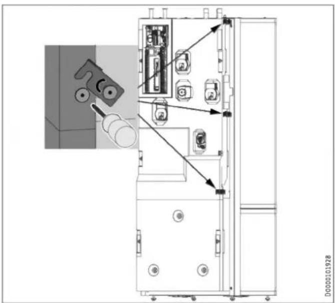
text_image
Technical diagram of an electrical cabinet with labeled components and directional arrows indicating assembly or connection.
Note
To make removal simpler, the insulation segments have labelled recessed grips on the left and right.
text_image
Technical diagram showing a device rear panel with labeled ports and an inset close-up of the handle, plus a 3D geometric triangle view.▶ Remove insulation segment 1.
▶ Remove insulation segment 2.

natural_image
Technical diagram showing a mechanical assembly with a magnified inset highlighting a component (no text or symbols present)▶ Pull the "heating sensor" out of the buffer cylinder.
natural_image
Technical line drawing of a mechanical assembly with pipes and housing (no text or symbols)▶ Release the sensor lead from the guide groove in the insulation segment.
natural_image
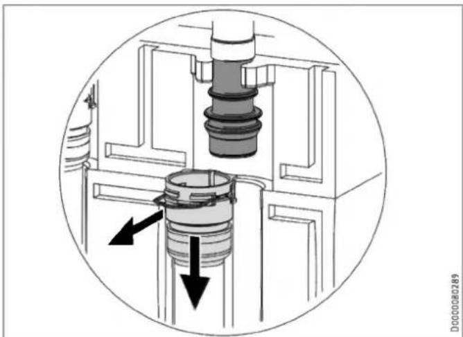
Cross-sectional diagram of a mechanical assembly showing internal components and directional arrows (no text or labels)▶ Disconnect the push-fit connectors of the 4 hydraulic connections. To do this, pull the spring clips fully out with a screwdriver.
▶ Pull the hydraulic connectors as indicated.
natural_image
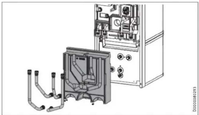
Technical line drawing of a mechanical assembly with pipes and control panel (no text or symbols)▶ Remove the 4 hydraulic hoses.
▶ Remove the 2 insulation material screws.
▶ Remove insulation segment 3.
natural_image
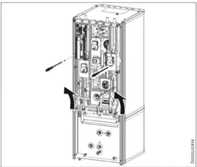
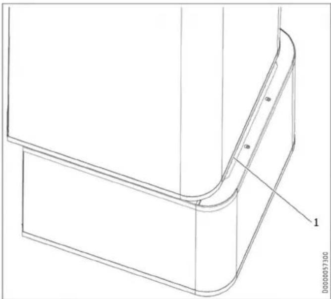
Technical diagram of an internal device with labeled ports and connectors (no readable text or symbols)▶ Undo the 2 locking screws on the side profile strips.
▶ Lift up and unhook the side profile strips.
natural_image
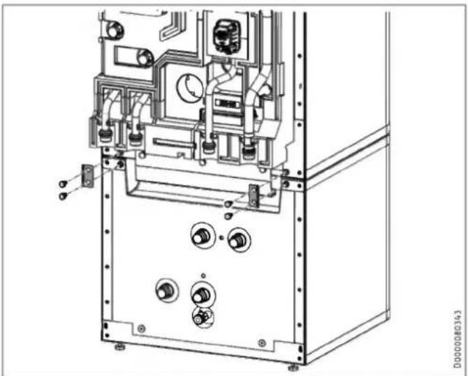
Technical line drawing of an industrial machine casing with internal components and mounting holes (no text or symbols)▶ Release the 4 screws on the tabs at the front of the appliance.
natural_image
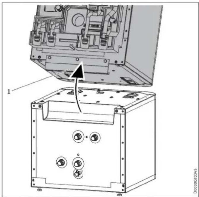
3D diagram of a mechanical component with a left-pointing arrow, no text or symbols present▶ Pull the upper section of the appliance towards the front.
natural_image
Technical diagram of an electronic device showing internal components and a base case with mounting holes (no text or symbols present)1 Handle
▶ Tip the upper section of the appliance backwards. Use the handle for improved grip.
natural_image
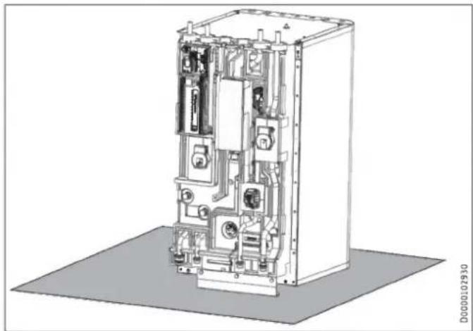
Technical line drawing of an electrical enclosure with internal components and wiring (no text or symbols)▶ Place the upper section of the appliance on a base to prevent damage.
Joining appliance sections

Material losses
To prevent condensation forming, the insulation segments must fit closely against the lower section with no gaps.
▶ When inserting the insulation segments, ensure that the joint grooves are kept clear.
▶ Tap the insulation segments down with your hand.
Rejoin the appliance sections in reverse order.
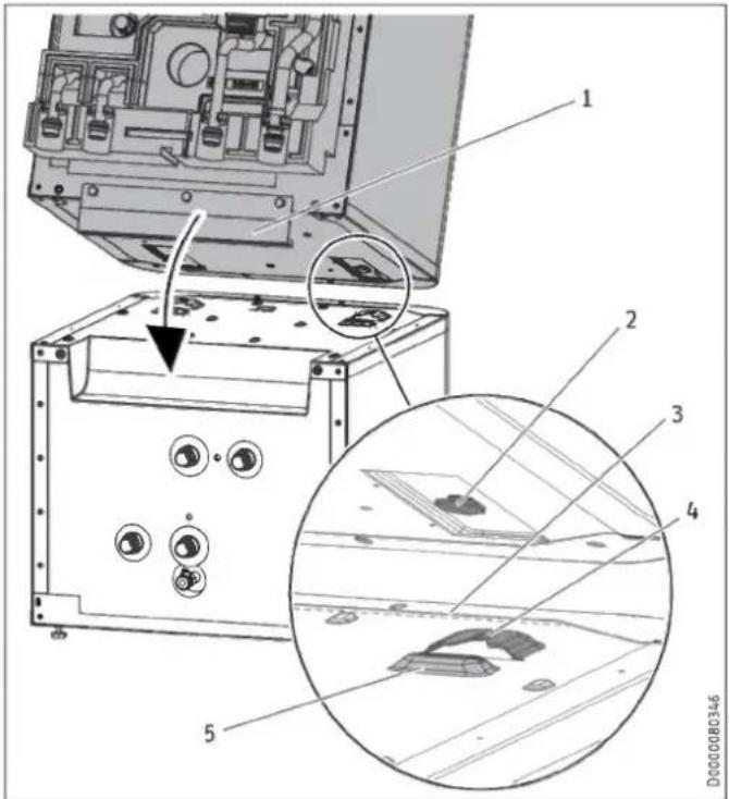
The positioning aids and the dotted line marking provide assistance when positioning and inserting the upper appliance section into the guide groove on the lower section:
text_image
Technical diagram of an electronic device with labeled components and a magnified inset showing internal structure details.1 Handle
2 Guide pin
3 Dotted line (perforation in the panel)
4 Guide groove
5 Positioning aid
natural_image
Technical line drawing of a mechanical component with curved and rectangular features (no text or symbols)1 Dotted line (perforation in the panel)
▶ Place the upper appliance section onto the lower appliance section along the dotted line.
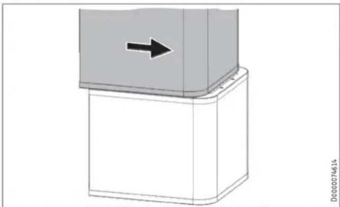
natural_image
3D diagram of a mechanical component with a black arrow indicating direction, no text or symbols present▶ Slide the upper appliance section to the back until it is flush with the lower appliance section. If the appliance sections are joined correctly, the final position is determined by the guide groove and guide pin.
▶ Secure the tabs on the appliance front.
▶ Fit the side profile strips.
▶ Fit insulation segment 3 and the 4 hydraulic hoses.
▶ Connect the push-fit connectors of the 4 hydraulic connections. Ensure that the spring clips click into place.
▶ Insert the "heating sensor" into the buffer cylinder.
▶ Lay the sensor lead in the guide groove provided for this purpose in the insulation segment.
▶ Fit insulation segment 2.
▶ Fit insulation segment 1.
▶ Fit the front casing.
10. Installation
10.1 Positioning the appliance
▶ When positioning the appliance, observe minimum clearances (see chapter "Preparations / Installation site").
▶ Use the adjustable feet to compensate for any unevenness in the floor.
10.2 Heating water connection

Material losses
The heating system to which the appliance is connected must be installed by a qualified contractor in accordance with the water installation drawings in the technical guides.

Material losses
When fitting additional shut-off valves, install a further safety valve in an accessible location on the heat generator itself or in the flow line in close proximity to the heat generator.
There must not be a shut-off valve between the heat generator and the safety valve.
Oxygen diffusion

Material losses
Do not use open vented heating systems. Use oxygen diffusion-proof pipes in underfloor heating systems with plastic pipework.
In underfloor heating systems with plastic pipes that are permeable to oxygen and in open vented heating systems, oxygen diffusion may lead to corrosion on the steel components of the heating system (e.g. on the indirect coil of the DHW cylinder, on buffer cylinders, steel radiators or steel pipes).
▶ With heating systems that are permeable to oxygen, separate the heating system between the heating circuit and the buffer cylinder.

Material losses
The products of corrosion (e.g. rusty sludge) can settle in the heating system components, which may result in a lower output or fault shutdowns due to reduced cross-sections.
Supply lines

Note
The maximum permissible line length between the appliance and the heat pump will vary, depending on the version of the heating system (pressure drop). As a standard value, assume a maximum line length of 10 m and a pipe diameter of 22-28 mm.
▶ Thoroughly flush the pipes before connecting the heat pump. Foreign bodies (e.g. welding pearls, rust, sand, sealing material, etc.) can impair the operational reliability of the system.
▶ Install the heating water pipes (see chapter "Specification / Dimensions and connections").
▶ Protect the flow and return lines against frost with sufficient thermal insulation.
▶ Connect the hydraulic connections with flat gaskets.
If the available external pressure difference is exceeded, the pressure drop in the heating system could result in a reduced heating output.
When sizing the pipes, ensure that the available external pressure differential is not exceeded (see chapter "Specification / Data table").
▶ When calculating the pressure drop, take account of the flow and return lines and the pressure drop of the heat pump. The pressure drop must be covered by the available pressure differential.
10.2.1 HSBC 3-HKM (optional)

WARNING Electrocution
Before starting work on the appliance, disconnect all poles from the power supply and drain the heating circuit via the drain valve on the buffer cylinder.
To extend the appliance with a heating circuit with mixer, you can install pump assembly HSBC 3-HKM (available as an accessory).
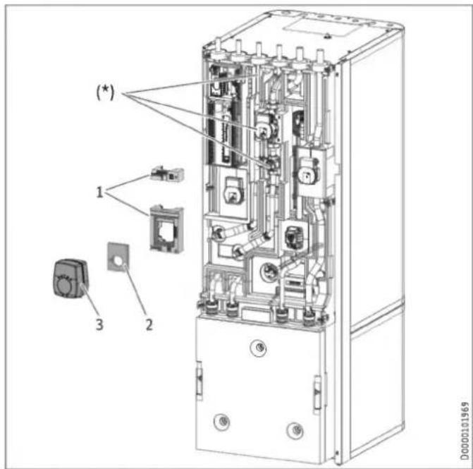
Standard delivery
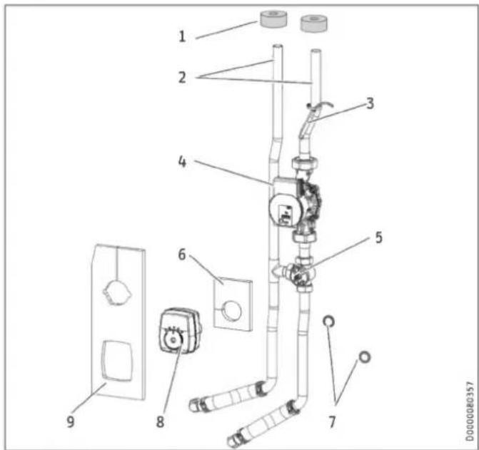
text_image
Technical diagram of a wall-mounted electrical switch assembly with numbered components1 Pipe insulation
2 Connection pipes (*)
3 Temperature sensor
4 Heating circuit pump (*)
5 3-way mixer (*)
6 Insulation mat for 3-way mixer
7 Flat gaskets
8 Servomotor for 3-way mixer (*)
9 Insulation mat for 3-way mixer and heating circuit pump (*) Pipe assembly
Preparation
▶ Remove the front casing and insulation segment 1 (see chapter "Installation / Preparations / Transport and handling").
The following components are prefitted on the HSBC side at the pump assembly installation site:
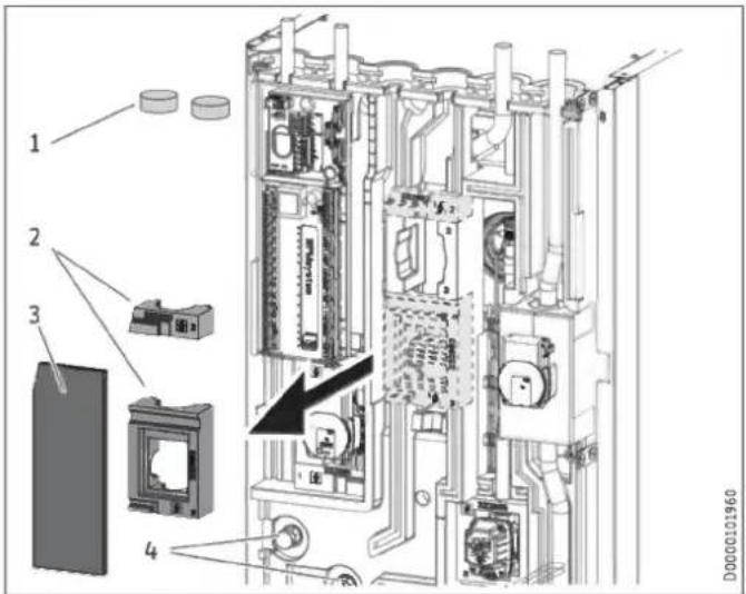
text_image
Technical diagram of an electronic device with numbered components and a highlighted internal mechanism1 Insulation plugs
2 Profiles for 3-way mixer
3 Insulation mat, closed
4 Adaptor with dummy cap screwed on
▶ Remove the insulation plugs.
▶ Remove the closed insulation mat and profiles for the 3-way mixer and the heating circuit pump.
▶ Counterhold and unscrew the dummy caps from the adaptors.
Installation
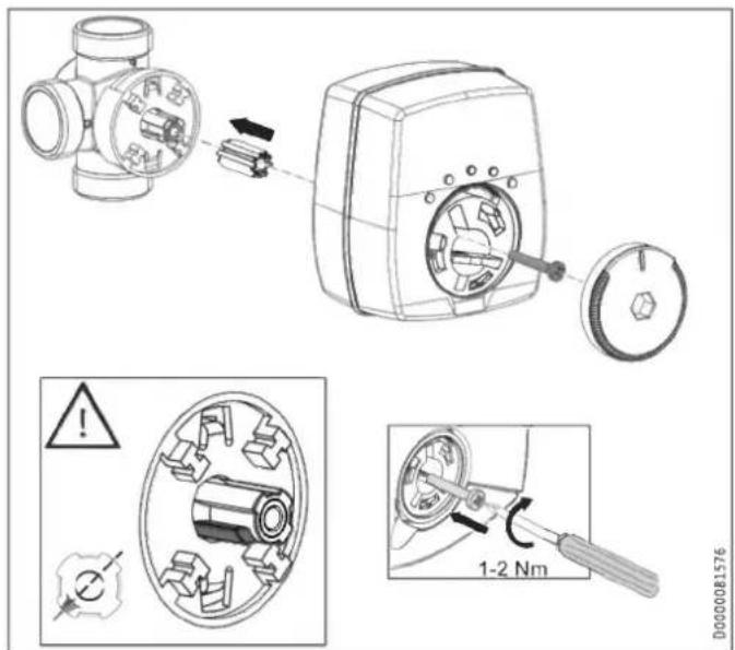
text_image
Technical diagram illustrating mechanical assembly steps with labeled components and warning indicators▶ Check the position of the 3-way mixer shaft.
▶ Adjust the position if necessary.
text_image
(*) 1 2 3 D0000101969(*) Pipe assembly inserted
1 Profiles for 3-way mixer
2 Insulation mat for 3-way mixer
3 Servomotor for 3-way mixer
▶ Insert the pipe assembly.
▶ Insert the flat gaskets into the union nuts for the connection pipes.
▶ Counterhold and secure the union nuts to the adaptors.
▶ Check the alignment of the pipes and functional elements of the pump assembly.
▶ Retighten all fittings.
▶ Install the profiles for the 3-way mixer over the mixing valve body and above the pump.
▶ Place the insulation mat for the 3-way mixer on the valve body.
▶ Install the servomotor for the 3-way mixer.
text_image
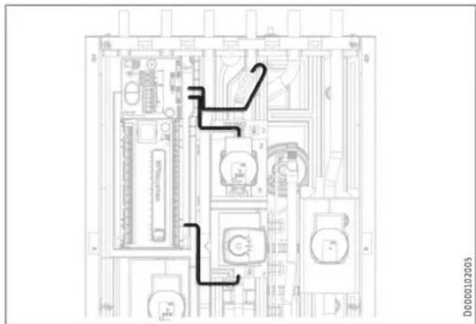
Technical diagram of an electronic device rear panel with labeled components and directional arrows indicating flow or movement.Material losses To prevent con
To prevent condensation from forming, do not lay any cables in the joint grooves of the EPP parts.
▶ Route the pump assembly connecting cable to the control panel as shown.
▶ Slide the pipe insulation over the connection pipe connectors from above.
text_image
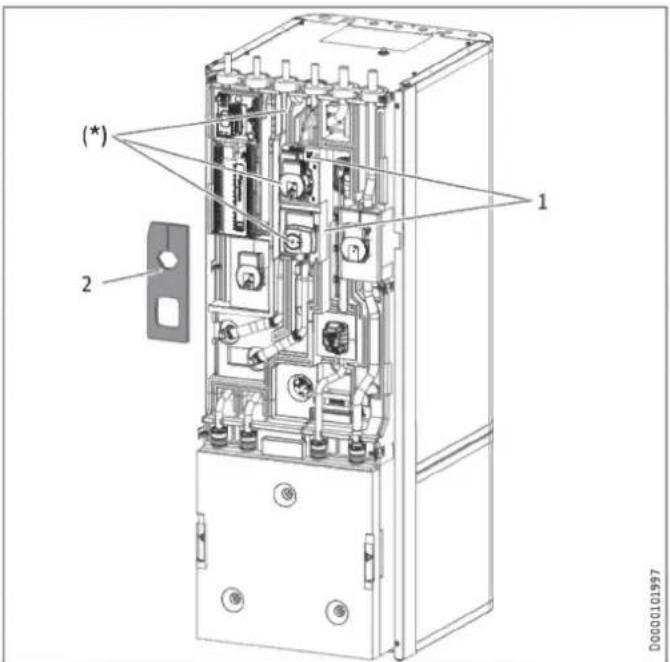
(*) 2 1 00000101997(*) Pipe assembly inserted
1 Profiles for 3-way mixer
2 Insulation mat for 3-way mixer and heating circuit pump
▶ Insert the insulation mat on the HKM side for the 3-way mixer and the heating circuit pump.
▶ Observe the parameter settings in menu "SETTINGS / HEATING / HEATING CIRCUIT 2" in the enclosed commissioning instructions for the heat pump manager.
10.3 DHW connection and safety assembly

Material losses
The maximum permissible pressure must not be exceeded (see chapter "Specification / Data table").

Material losses
Operate the appliance only with pressure-tested taps.
Cold water line
Galvanised steel, stainless steel, copper and plastic are approved materials.

Material losses
A safety valve is required.
Stainless steel, copper and plastic are approved materials.
10.3.1 DHW connection and safety assembly
▶ Flush the pipes thoroughly.
▶ Install the DHW outlet line and the cold water inlet line (see chapter "Specification / Dimensions and connections"). Connect the hydraulic connections with flat gaskets.
▶ Install a type-tested safety valve in the cold water supply line. Please note that, depending on the supply pressure, you may also need a pressure reducing valve.
▶ Size the drain pipe so that water can drain off unimpeded when the safety valve is fully opened.
▶ The safety valve drain aperture must remain open to atmosphere.
▶ Install the safety valve drain pipe with a constant fall to the drain.
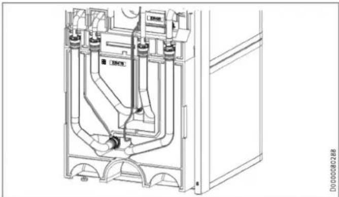
10.3.2 RBS-SBC (optional)

WARNING Electrocution
Before starting work on the appliance, disconnect all poles from the power supply and drain the DHW cylinder.

Note
The following diagrams show pipe assembly RBS-SBC (see chapter "Specification / Dimensions and connections").
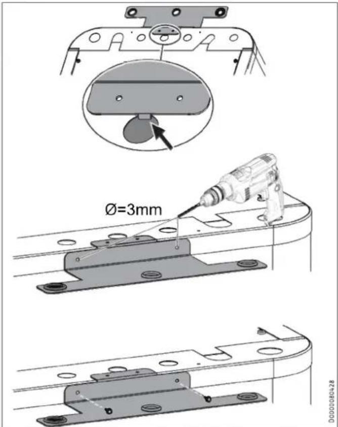
text_image
Ø=3mm 00000004-28▶ Hook the retainer for the connection pipes into the top centre of the appliance.
▶ Use the retainer as a drilling template and pre-drill the fixing holes.
▶ Secure the retainer with the screws.
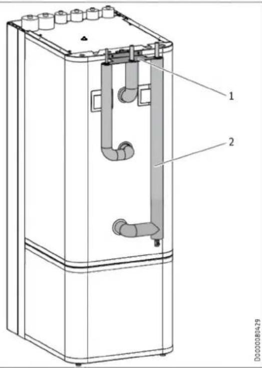
text_image
Technical diagram of a refrigerant or gasifier unit with labeled components and pipe connections1 Retainer
2 Insulated connection pipes
▶ Install the connection pipes in sequence, starting on the left or right depending on the positioning of the appliance.
▶ Insert the connection pipes through the retainer from below.
▶ Secure the connections to the appliance using the union nuts
▶ Connect the pipes of the pipe assembly to the domestic pipework system.
10.3.3 DHW circulation line (optional)
A DHW circulation line with external DHW circulation pump can be fitted to the DHW circulation connection (see chapter "Specification / Dimensions and connections").
▶ Remove the sealing cap from the DHW circulation connection (see chapter "Specification / Dimensions and connections").
▶ Connect the DHW circulation line.
10.4 Filling the system

Material losses
Never switch on the power before filling the system.
10.4.1 Heating circuit water quality
The heating system is filled with drinking water. To prevent damage to the heating system, comply with the following limits.
| Unit | Value | |
| Water hardness | ^ dH | ≤ 3 |
| pH value | 6.5-8.5 | |
| Chloride | mg/l | < 30 |
You can find out the water hardness and the chloride value in the fill water from the local water supplier.
▶ Observe local requirements (e.g. VDI 2035 in Germany).
We do not recommend desalinating the fill water, as this may cause a negative change in the pH value.
▶ If you desalinate the fill water or the pH value of the fill water is less than 8.2, check the pH value 8 to 12 weeks after installation, every time the system is topped up and the next time it is serviced.
▶ Do not add inhibitors or additives to the filling water.
Accessories for water softening
If you need to soften the fill water, you can use the following product.
- Heating water softener HZEA
- HZEN replacement cartridge
▶ Recheck these limits 8-12 weeks after commissioning, every time the system is topped up and during the annual service.
Appliance in low-occupancy buildings
During regular operation, the connection lines and the system are protected by the frost protection function of the appliance.
If the appliance is disconnected from the power supply for a longer period of time (shutdown, prolonged power failure), drain the appliance on the water side. Otherwise the appliance is not protected against frost.
If it is not possible to detect power failures (for example if the system is in a holiday home left vacant for extended periods of time), the following protective measure can be taken.
▶ Add a suitable concentration of ethylene glycol to the fill water (20-40 % by vol.). Observe the instructions for the antifreeze. Only use antifreeze products which have been approved by us.
▶ Please note that antifreeze changes the density and viscosity of the fill water.
MEG 10 Heat transfer medium as concentrate on an ethylene glycol base
MEG 30 Heat transfer medium as concentrate on an ethylene glycol base
10.4.2 Filling the heating system

Material losses
Residual glycol in the hoses can make the heating water acidic. Corrosion and malfunctions may occur as a result.
▶ Use separate hoses for glycol and heating water.
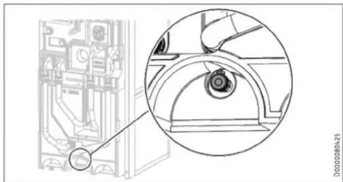
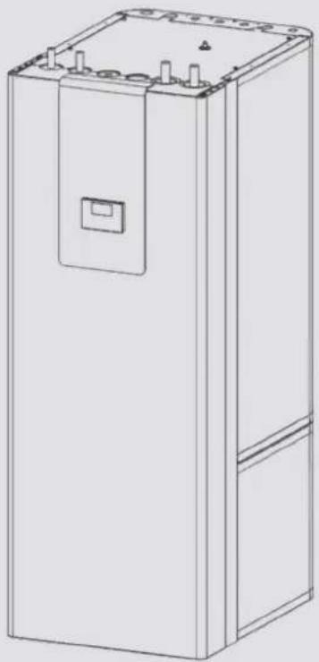
natural_image
Technical line drawing of a mechanical assembly with an inset close-up showing a circular component detail (no text or symbols)▶ Fill the heating system via the drain valve.
▶ Vent the pipework.
▶ Filling the DHW cylinder via the cold water inlet connection.
▶ Open all downstream draw-off valves until the appliance is full and the pipework is free of air.
▶ Adjust the flow rate. For this, observe the maximum permissible flow rate with a fully opened tap (see chapter "Specification / Data table"). If necessary reduce the flow rate at the butterfly valve of the safety assembly.
▶ Carry out a tightness check.
▶ Check the safety valve.
10.5 Venting the appliance
text_image
Technical diagram of an electrical switchgear assembly with labeled components and a magnified view showing internal wiring.1 Air vent valve
2 Vent hose
3 Hose attachment
▶ Detach the vent hose from the hose attachment.
▶ Hang the free end of the vent hose in a container.
▶ To ventilate, open the air vent valve.
▶ After ventilation, close the air vent valve.
▶ Secure the vent hose.
11. Electrical connection

WARNING Electrocution
Carry out all electrical connection and installation work in accordance with relevant regulations.
Before any work on the appliance, disconnect all poles from the power supply.

Material losses
Provide separate fuses for the two power circuits of the appliance and the control unit.

Material losses
Observe the type plate. The specified voltage must match the mains power supply.

Note
Leakage currents of up to 5 mA may occur.
The connection to the power supply must be in the form of a permanent connection.
▶ Install a safety device to enable the unit to be separated from the power supply over an isolating distance of 3 mm. Safety devices include, for example, contactors, circuit breakers, fuses/MCBs.
The terminal box of the appliance is located behind the front casing (see chapter "Preparations / Transport and handling / Removing/ fitting the front casing").
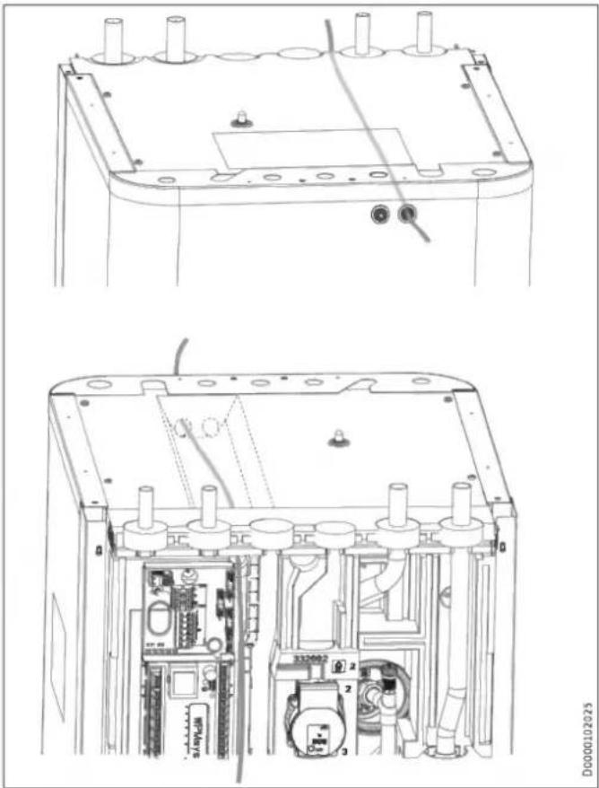
natural_image
Technical line drawings of a device interior showing internal components and mounting brackets (no text or symbols)▶ Route all power cables and sensor leads into the appliance through the cable entry.
▶ Connect the power cables and sensor leads as detailed below.
Install cables with the following cross-sections in accordance with the respective fuse protection:
| Fuse protection | Assignment | Cable cross-section |
| B 16 A | Control unit | 1.5 mm^2 |
11.1 Control voltage
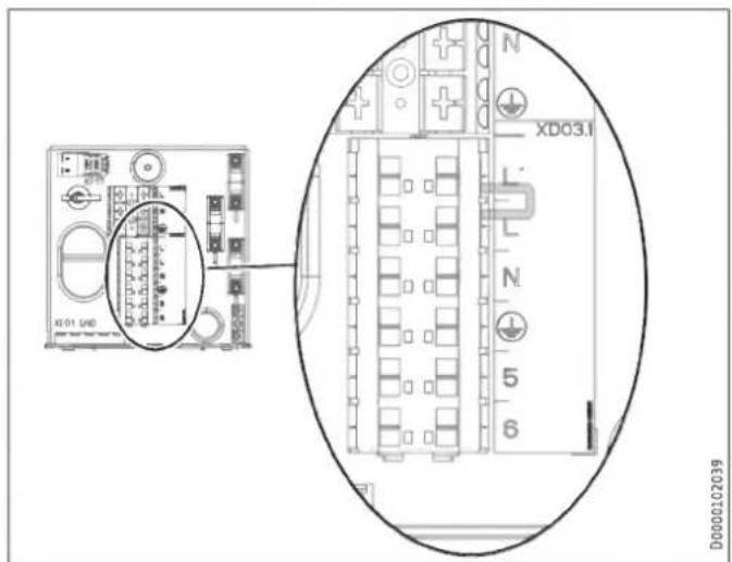
text_image
XD01 (640) XD03.1 L' L N 5 6 D00002C2039Terminal Control voltage
| XD03.1 | Power supplyL, N, PE |
| Power input of power supply utilityL' |
▶ If no ripple control receiver is fitted, install a jumper between L and L'.
11.2 Safety extra low voltage
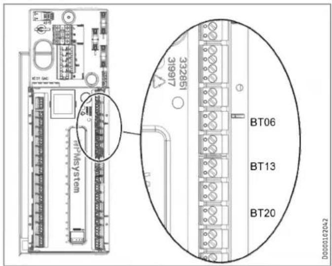
text_image
KT21 GAC 332851 31997 MT-MSystem BT06 BT13 BT20 D00000102042| Termi-nal | Safety extra low voltage | |
| AA01-X1.1 | Heat pump | |
| AA01-X1.3 | Outside sensor | |
| AA01-X1.4 | BT06 | Temperature sensor, heat pump, buffer cylinder |
| AA01-X1.6 | BT13 | Temperature sensor, heat pump, flow, heating circuit 2 (HSBC 3-HKM accessory) |
| AA01-X1.8 | BT20 | DHW cylinder temperature sensor |
Control by WPM via PWM signal
▶ Observe the information in the commissioning instructions for the WPM heat pump manager.
11.3 Heat pump manager terminal assignment

WARNING Electrocution
Only components that operate with safety extra low voltage (SELV) and that ensure secure separation from the mains voltage supply may be connected to the low voltage terminals of the appliance.
Connecting other components can make parts of the appliance and connected components live.
▶ Only use components which have been approved by us.
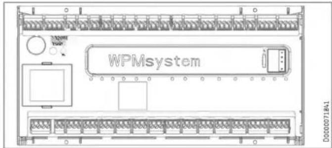
text_image
WPMsystem D000071841Safety extra low voltage
| X1.1CAN A | + | + | CAN (connection for heat pump and WPE heat pump extension) |
| - | - | ||
| L | L | ||
| H | H | ||
| X1.2CAN B | + | + | CAN (connection for FET remote control and ISG Internet Service Gateway) |
| - | - | ||
| L | L | ||
| H | H | ||
| X1.3 | Signal | 1 | Outside sensor |
| Earth | 2 | ||
| X1.4 | Signal | 1 | Buffer sensor (heating circuit sensor 1) |
| Earth | 2 | ||
| X1.5 | Signal | 1 | Flow sensor |
| Earth | 2 | ||
| X1.6 | Signal | 1 | Heating circuit sensor 2 |
| Earth | 2 | ||
| X1.7 | Signal | 1 | Heating circuit sensor 3 |
| Earth | 2 | ||
| X1.8 | Signal | 1 | DHW cylinder sensor |
| Earth | 2 | ||
| X1.9 | Signal | 1 | Source sensor |
| Earth | 2 | ||
| X1.10 | Signal | 1 | 2nd heat generator (2.WE) |
| Earth | 2 | ||
| X1.11 | Signal | 1 | Cooling flow |
| Earth | 2 | ||
| X1.12 | Signal | 1 | DHW circulation sensor |
| Earth | 2 | ||
| X1.13 | Signal | 1 | FE7 remote control / telephone remote switch / heating curve optimisation / SG Ready |
| Earth | 2 | ||
| Signal | 3 | ||
| X1.14 | Constant 12 V | + | Analogue input 0-10 V |
| Input | IN | ||
| GND | |||
| X1.15 | Constant 12 V | + | Analogue input 0-10 V |
| Input | IN | ||
| GND | |||
| X1.16 | Signal | 1 | PWM output 1 |
| Earth | 2 | ||
| X1.17 | Signal | 1 | PWM output 2 |
| Earth | 2 |
Safety extra low voltage
| X1.18CAN B | + | + | CAN (connection for programming unit) |
| - | - | ||
| L | L | ||
| H | H | ||
| X1.19CAN A | + | + | CAN (connection for heat pump and WPE heat pump extension) |
| - | - | ||
| L | L | ||
| H | H |
Mains power supply
| X2.1 | L | L | Power supply |
| L | L | ||
| N | N | ||
| PE | |||
| X2.2 | L' (power supply utility input) | L' | L' (power supply utility input) |
| L* (pumps L) | L* (pumps L) | L* (pumps L) | |
| X2.3 | L | L | Heating circuit pump 1 |
| N | N | ||
| PE | PE | ||
| X2.4 | L | L | Heating circuit pump 2 |
| N | N | ||
| PE | PE | ||
| X2.5 | L | L | Heating circuit pump 3 |
| N | N | ||
| PE | PE | ||
| X2.6 | L | L | Buffer charging pump 1 |
| N | N | ||
| PE | PE | ||
| X2.7 | L | L | Buffer charging pump 2 |
| N | N | ||
| PE | PE | ||
| X2.8 | L | L | DHW charging pump |
| N | N | ||
| PE | PE | ||
| X2.9 | L | L | Source pump / defrost |
| N | N | ||
| PE | PE | ||
| X2.10 | L | L | Fault output |
| N | N | ||
| PE | PE | ||
| X2.11 | L | L | DHW circulation pump / 2nd heat source DHW |
| N | N | ||
| PE | PE | ||
| X2.12 | L | L | 2nd heat source heating |
| N | N | ||
| PE | PE | ||
| X2.13 | L | L | Cooling |
| N | N | ||
| PE | PE | ||
| X2.14 | Mixer OPEN | ▲ | Mixer, heating circuit 2(X2.14.1 Mixer OPEN X2.14.2 Mixer CLOSE) |
| N | N | ||
| PE | PE | ||
| Mixer CLOSE | ▼ | ||
| X2.15 | Mixer OPEN | ▲ | Mixer heating circuit 3(X2.15.1 Mixer OPEN X2.15.2 Mixer CLOSE) |
| N | N | ||
| PE | PE | ||
| Mixer CLOSE | ▼ |

Note
For every appliance fault, output X2.10 issues a 230 V signal.
In the case of temporary faults, the output switches the signal through for a specific time.
In the case of faults that result in a permanent appliance shutdown, the output switches through permanently.
11.4 Accessories
11.4.1 HSBC 3-HKM (optional)
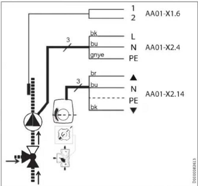
text_image
1 2 AA01-X1.6 bk bu gnye L N PE AA01-X2.4 3 br bu bk ▲ N PE AA01-X2.14 3 DG00082613| Terminal | Safety extra low voltage | ||
| AA01-X1.6 | BT13 | Temperature sensor, heat pump flow, heating circuit 2 | |
| Terminal | Mains power supply | ||
| AA01-X2.4 | L, N, PE | MA11 | Motor, pump, heating circuit |
| AA01-X2.14 | L, L, N | MA19 | Motor, mixing valve heating circuit 2 |
▶ Make the electrical connection for the components.
11.4.2 STB-FB high limit safety cut-out for underfloor heating systems (optional)
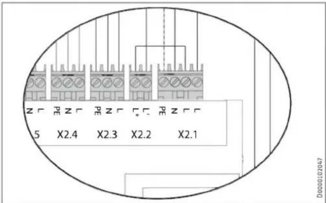
text_image
5 X2.4 X2.3 X2.2 X2.1 D0000102047▶ X2.1 (L), X2.2 (L ^* ): Remove the jumper.
▶ X2.1 (L), X2.2 (L*): Connect the high limit safety cut-out to the terminals.
11.5 Sensor installation
11.5.1 AF PT outside temperature sensor
11.5.2 Temperature sensor for area cooling (optional)
▶ When installing the outside temperature sensor, observe the commissioning instructions for the heat pump manager (see chapter "Connecting external components").
Area cooling requires the fitting of a temperature sensor, available as an accessory.
▶ Remove the front casing (see chapter "Preparations / Transport and handling / Removing/fitting the front casing").
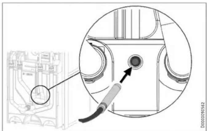
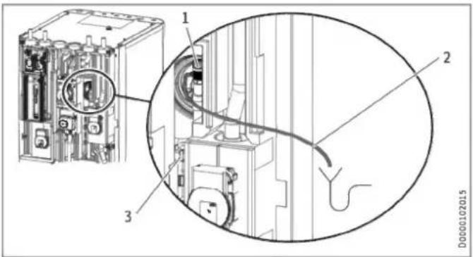
natural_image
Technical diagram showing a mechanical component with an inset close-up of a circular component, no visible text or symbols.▶ Insert the temperature sensor into the sensor well "Sensor heat pump cooling, optional".
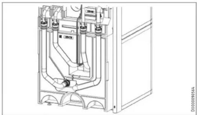
natural_image
Technical line drawing of a mechanical assembly with pipes and components (no text or symbols)▶ Lay the sensor lead in the guide groove provided for this purpose in the insulation segment.
Connect the temperature sensor to the corresponding terminal on the WPM (see chapter "Electrical connection / Heat pump manager terminal assignment").
11.6 Remote control
When installing the remote control unit, observe the commissioning instructions for the heat pump manager (see chapter "Connecting external components").
12. Commissioning
Our customer support can assist with commissioning, which is a chargeable service.
If the appliance is intended for commercial use, observe the rules of the relevant Health & Safety at Work Act during commissioning. For further details, check with your local authorising body (in Germany, for example, this is the TÜV).
12.1 Checks before commissioning the heat pump manager

Material losses
Observe the maximum system temperature in underfloor heating systems.
▶ Check that the heating system is filled to the correct pressure and the quick-action air vent valve is closed.
▶ Check whether the outside temperature sensor is correctly placed and connected.
▶ Check whether the power supply is connected correctly.
▶ Check whether the signal cable to the heat pump (bus cable) is correctly connected.
12.2 Commissioning the heat pump manager
Commission the heat pump manager and make all settings in accordance with the heat pump manager commissioning instructions.

Note
The required settings on the heat pump manager are preset using an SD card.
▶ If the heat pump manager has had to be replaced, perform the following settings.
Requirement: The heat pump manager has recognised the heat pump.
▶ Open the menu and enter the code.
| Parameter | Code |
| VIEW (SETTINGS) | 1 0 0 0 |
▶ Adjust the parameters.
| Parameter | Setting |
| DHW MODE (SETTINGS / DHW / STANDARD SETTING) | PARALLEL OPERATION |
| FUNCTION (COMMISSIONING / I/O CONFIGURATION / OUTPUT X1.16) | PWM 100%...0% |
| PUMP (COMMISSIONING / I/O CONFIGURATION / OUTPUT X1.16) | CHARGING PUMP CONTROL HEATING |
Setting for single-phase operation

Note
On appliances with a single phase connection, set the heat pump manager as follows for calculating the amount of heat.
▶ Adjust the parameters.
| Parameter | Setting |
| NUMBER OF STAGES (SETTINGS / HEATING / ELECTRIC BOOSTER HEATER) | 2 |
Area cooling setting

Material losses
Condensation caused by the temperature falling below the dew point can lead to material losses. The appliance is therefore approved exclusively for area cooling.
▶ When making the area cooling settings, observe the information in the commissioning instructions for the heat pump manager.
13. Settings
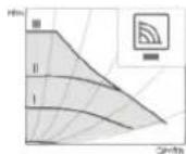
13.1 Wilo-Para .../Sc circulation pumps
▶ Set the operating mode of the pump depending on the heat distribution system.
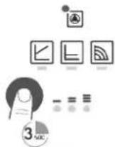
LED indicators
| Operation indicator:LED illuminates green in normal operationLED illuminates/flashes when there is a fault | |
| Display of selected control mode p-v , p-c and constant speed | |
| Display of selected curve (I, II, III) within the control mode | |
| Combinations of LED displays for venting function, manual re-start and key lock |
Operating button
Press
Selecting the control mode
To select the curve (I, II, III) within the control mode
Press and hold
To activate the venting function (press for 3 seconds)
Manual restart (press for 5 seconds)
To lock/unlock the buttons (press for 8 seconds)
Control modes and functions
Variable differential pressure p-v (I, II, III)
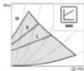
Recommended for two-pipe heating systems with radiators to reduce flow noise at thermostatic valves
The pump reduces the delivery head by half when the flow rate in the pipework decreases.
Saves energy by matching the delivery head to the flow rate demand and the lower flow velocities.
Choice of three pre-defined curves (I, II, III).
Constant pressure differential p-c (I, II, III)
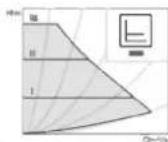
Recommended for underfloor heating systems, large pipework or any application with a non-varying pipework curve (e.g. cylinder charging pumps), as well as single-pipe heating systems with radiators
The control system keeps the set delivery head constant, irrespective of delivered flow rate.
Choice of three pre-defined curves (I, II, III).
Constant speed (I, II, III)
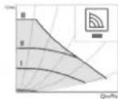
Recommended for systems with unchanging system resistance which require a constant throughput.
The pump runs at three preset fixed speed levels (I, II, III).

Note
Factory setting: Constant speed, curve III
Venting
Filling and venting the system correctly
If the pump does not vent automatically:
Activate the venting function via the operating button,
press button for 3 seconds, then release it.
Venting function starts (duration 10 minutes).
The top and bottom rows of LEDs flash alternately every second.
To cancel, press the operating button for 3 seconds.
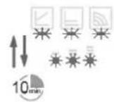

Note
After venting, the LED indicator displays the previously set pump values.
Setting control modes
Selecting the control mode
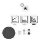
The LEDs for the control modes and associated curves illuminate one after the other.
Briefly press the operating button (for approx. 1 second).
LEDs indicate the current selected control mode and curve (see following table).
(*)Pressing the button for the 9th time in succession returns the system to the factory setting (constant speed, curve III).
| Operating button | LED indicator | Control mode | Curve |
| 1x | Constant speed | II | |
| 2x | Constant speed | I | |
| 3x |  | Variable differential pressure Δp-v | III |
| 4x |  | Variable differential pressure Δp-v | II |
| 5x |  | Variable differential pressure Δp-v | I |
| 6x |  | Constant differential pressure Δp-c | III |
| 7x |  | Constant differential pressure Δp-c | II |
| 8x |  | Constant differential pressure Δp-c | I |
| *9x |  | Constant speed | III |
14. Appliance handover
Explain the appliance function to users and familiarise them with how it works.
▶ Make users aware of potential dangers.
▶ Hand over these instructions.
15. Shutting down the system

Material losses
Observe the temperature application limits and the minimum circulation volume on the heat consumer side (see chapter "Specification / Data table").

Material losses
Drain the system when there is a risk of frost and the heat pump is completely switched off (see chapter "Maintenance / Draining the DHW cylinder").
▶ If you take the system out of use, set the heat pump manager to standby so that the safety functions that protect the appliance (e.g. frost protection) remain active.
16. Maintenance

WARNING Electrocution
Carry out all electrical connection and installation work in accordance with relevant regulations.

WARNING Electrocution
Before any work on the appliance, disconnect all poles of the appliance from the power supply.
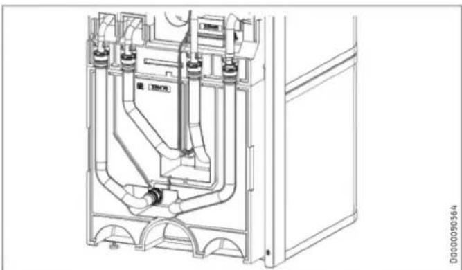
Draining the buffer cylinder
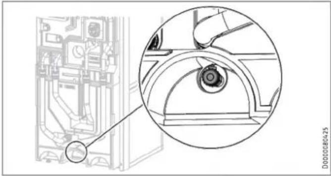
natural_image
Technical line drawing of a mechanical component with an inset close-up view (no text or symbols)▶ Drain the buffer cylinder via the drain valve.
Hot water may escape during draining.
▶ Close the shut-off valve in the cold water supply line.
▶ Open the hot water taps on all draw-off points.
▶ Empty the DHW cylinder via the cold water inlet connection.
Cleaning and descaling the DHW cylinder

Material losses
Never use descaling pumps or descaling agents to clean the cylinder.
▶ Clean the appliance through the inspection flange.
For the torque of the flange screws, see chapter "Specification / Dimensions and connections".
Replacing the signal anode
▶ Replace the signal anode if it becomes depleted.
17. Specification
17.1 Dimensions and connections
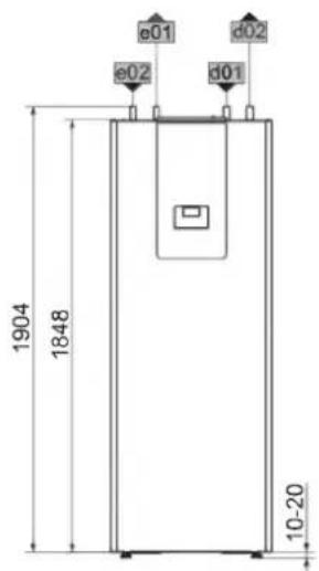
text_image
1904 1848 e01 e02 d01 d02 10-20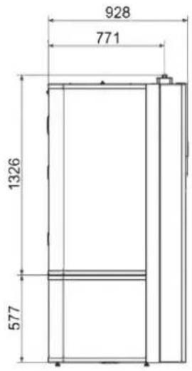
text_image
928 771 1326 577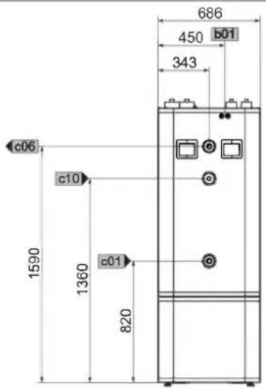
text_image
686 450 b01 343 c06 c10 1590 1360 c01 820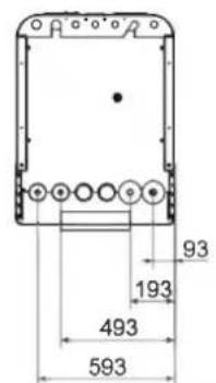
text_image
93 193 493 593D0000102170
| HSBC 300 cool | ||||
| b01 | Entry electrical cables | |||
| c01 | Cold water inlet | Male thread | G 1 | |
| c06 | DHW outlet | Male thread | G 1 | |
| c10 | DHW circulation | Male thread | G 1/2 | |
| d01 | Heat pump flow | Diameter | mm | 28 |
| d02 | Heat pump return | Diameter | mm | 28 |
| e01 | Heating flow | Diameter | mm | 22 |
| e02 | Heating return | Diameter | mm | 22 |
Other dimensions and connections
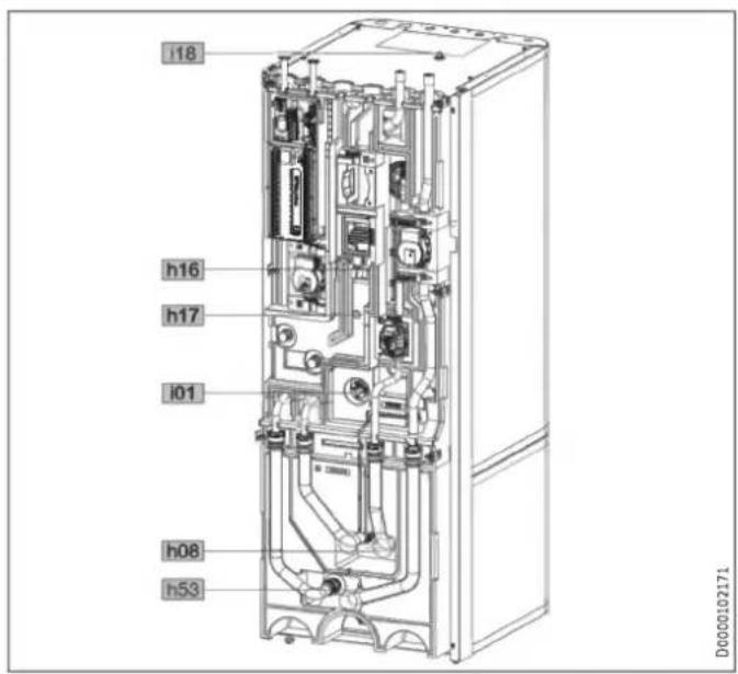
text_image
i18 h16 h17 i01 h08 h53 D0000102171| HSBC 300 cool | ||||
| h08 | Sensor heat pump cooling, optional | Diameter | mm | 9.5 |
| h16 | Sensor DHW | Diameter | mm | 9.5 |
| h17 | Sensor, DHW, optional | Diameter | mm | 9.5 |
| h53 | Sensor heating | Diameter | mm | 9.5 |
| i01 | Flange | External diameter | mm | 140 |
| Torque | Nm | 45 | ||
| i18 | Protective anode | Female thread | G 1 1/4 | |
RBS-SBC
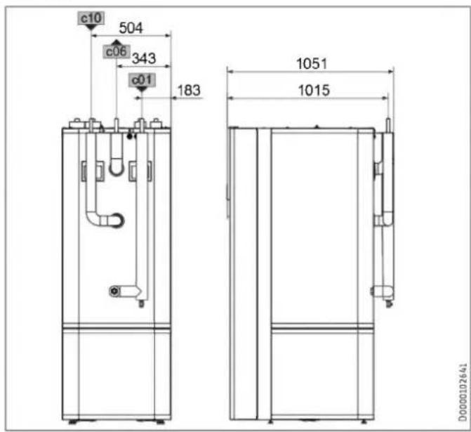
text_image
c10 504 c06 343 c01 183 1051 1015 D0000102641| RBS-SBC | ||||
| c01 | Cold water inlet | Diameter | mm | 22 |
| c06 | DHW outlet | Diameter | mm | 22 |
| c10 | DHW circulation | Diameter | mm | 12 |
17.1.1 Accessories
HSBC 3-HKM
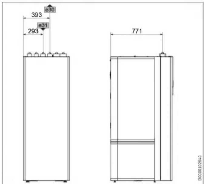
text_image
393 e30 e31 293 771 D0000102640| HSBC 3-HKM | ||||
| e30 | Heating flow, mixed | Diameter | mm | 22 |
| e31 | Heating return, mixed | Diameter | mm | 22 |
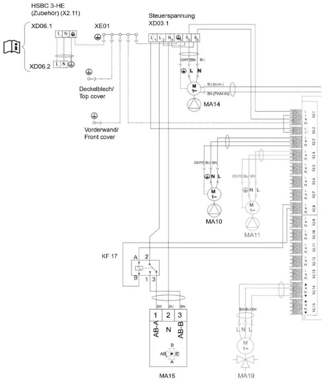
17.2 Wiring diagram
flowchart
graph TD
    A["HSBC 3-HE (Zubehör) (X2.11)"] --> B["XD06.1"]
    A --> C["XE01"]
    B --> D["Deckelblech/Top cover"]
    C --> E["Steuerspannung XD03.1"]
    D --> F["Vorderwand/Front cover"]
    E --> G["Steuerspannung XD03.1"]
    H["KA 17"] --> I["MA15"]
    I --> J["MA19"]
    K["Steuerspannung XD03.1"] --> L["GNYE BN BU"]
    L --> M["M 1~"]
    M --> N["BU (com.)"]
    M --> O["BN (PWM IN)"]
    P["Steuerspannung XD03.1"] --> Q["MA14"]
    Q --> R["GNYE BU BN"]
    R --> S["N L"]
    S --> T["M 1~"]
    T --> U["MA10"]
    U --> V["GNYE BU BN"]
    V --> W["N L"]
    W --> X["M 1~"]
    X --> Y["MA11"]
    Y --> Z["GNYE BU BN"]
    Z --> AA["N L"]
    AA --> AB["M 1~"]
    AB --> AC["MA10"]
    AC --> AD["GNYE BU BN"]
    AD --> AE["N L"]
    AE --> AF["M 1~"]
    AF --> AG["MA11"]
    AG --> AH["GNYE BU BN"]
    AH --> AI["N L"]
    AI --> AJ["M 1~"]
    AJ --> AK["MA10"]
    AK --> AL["GNYE BU BN"]
    AL --> AM["N L"]
    AM --> AN["M 1~"]
    AN --> AO["GNYE BU BN"]
    AO --> AP["N L"]
    AP --> AQ["M 1~"]
    AQ --> AR["GNYE BU BN"]
    AR --> AS["N L"]
    AS --> AT["M 1~"]
    AT --> AU["GNYE BU BN"]
    AU --> AV["N L"]
    AV --> AW["M 1~"]
    AW --> AX["GNYE BU BN"]
    AX --> AY["N L"]
    AY --> AZ["M 1~"]
    AZ --> BA["GNYE BU BN"]
D0000093952
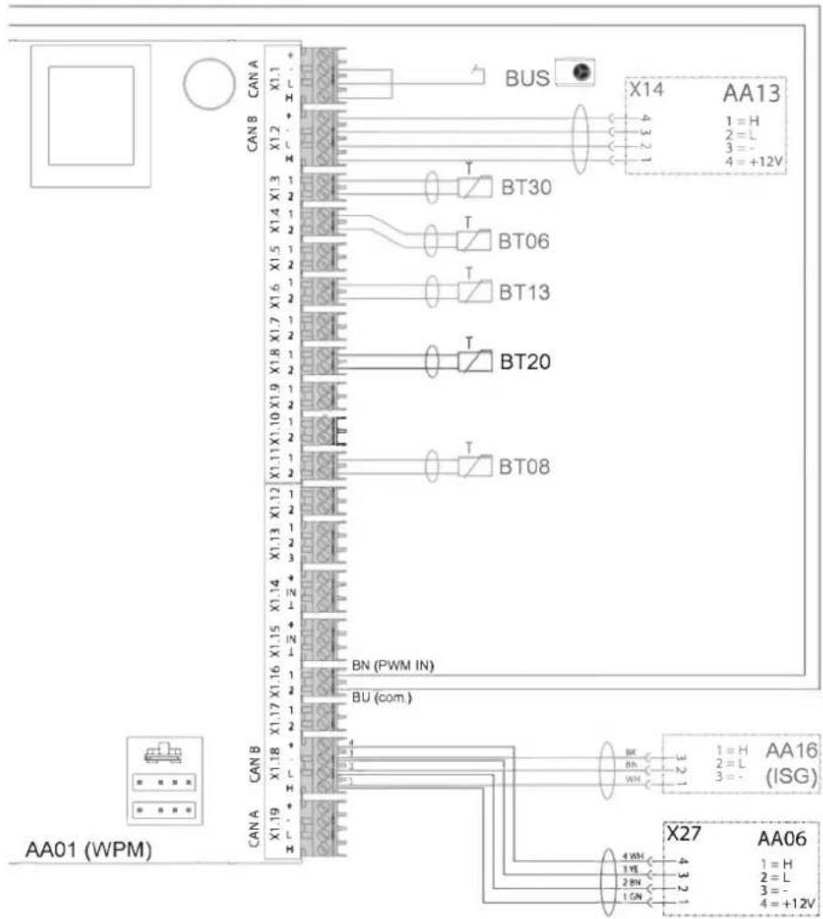
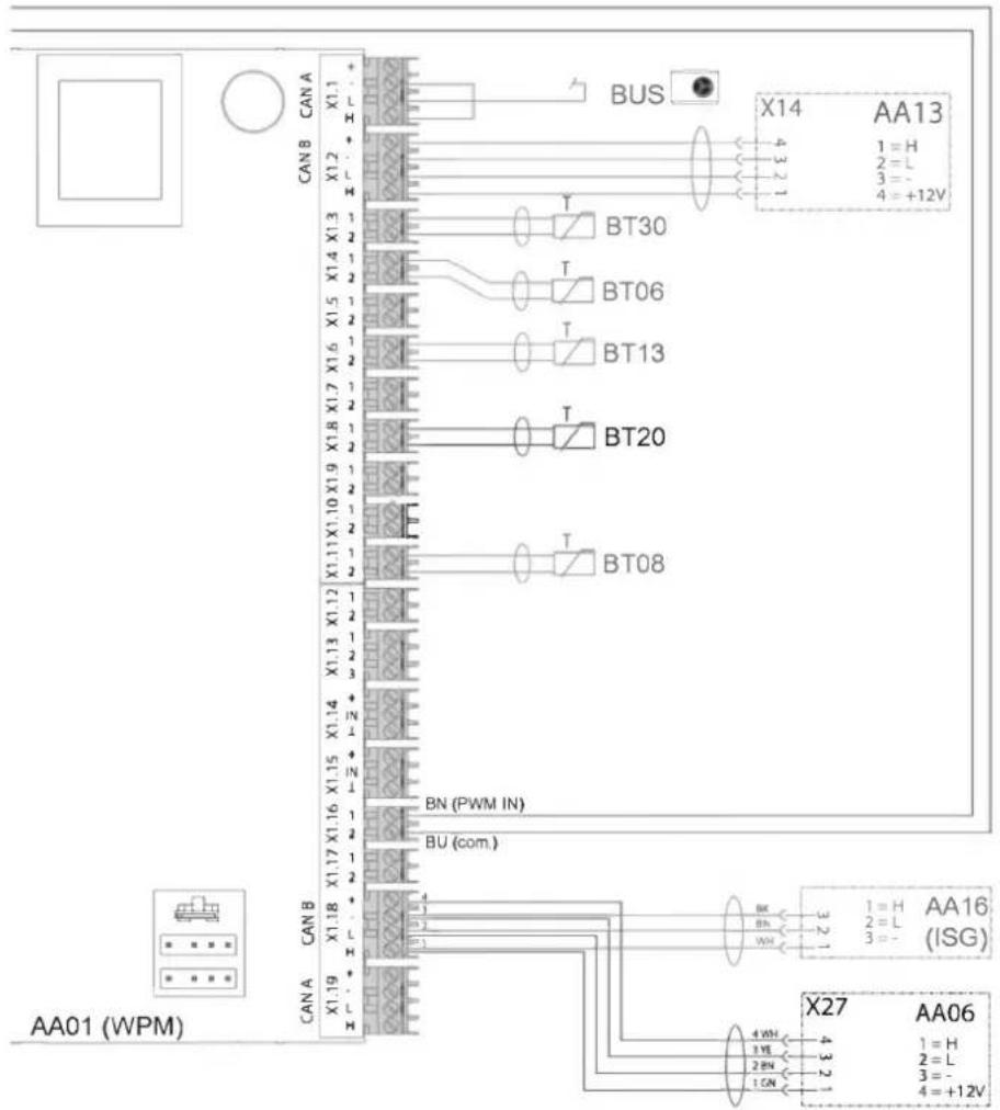
text_image
AA01 (WPM) CAN A CAN B X1.19 X1.18 X1.17 X1.16 X1.15 X1.14 X1.13 X1.12 X1.11 X1.10 X1.9 X1.8 X1.7 X1.6 X1.5 X1.4 X1.3 X1.2 CAN B CAN A BU (com.) BN (PWM IN) BT08 BT20 BT13 BT06 BT30 BUS X27 AA06 3 2 1 H 2 H 3 H 4 H 5 H 6 H 7 H 8 H 9 H 10 H 11 H 12 H X14 AA13 4 3 2 H 2 H 3 H 4 H 5 H 6 H 7 H 8 H 9 H 10 H 11 H 12 H 3 2 1 H 2 H 3 H 4 H 5 H 6 H 7 H 8 H 9 H 4 3 2 H 2 H 3 H 4 H 5 H 6 H 7 H 8 H 9 H 4 3 2 H 2 H 3 H 4 H 5 H 6 H 7 H 8 H 9 H 4 3 2 H 2 H 3 H 4 H 5 H 6 H 7 H 8 H 9 H 4 3 2 H 2 H 3H 4 3 2 H 2 H 3H 4 3 2 H 2 H 3H 4 3 2 H 2 H 3H 4 3 2 H 2 H 3H 4 3 2 H 2 H 3H 4 3 2 H 2 H 3H 4 3 2 H 2 H 3H 4 3 2 H 3H 4 3 2 H 4 3 2 H 4 3 2 H 4 3 2 H 4 3 2 H 4 3 2 H 4 3 2 H 4 3 2 H 4 3 2 H 4 3 2 H 4 3 2 H 4 3 2 H 4 3 2 H 4.5V 4.5V 4.5V 4.5V 4.5V 4.5V 4.5V 4.5V 4.5V 4.5V 4.5V 4.5V 4.5V 4.5V 4.5V 4.5V 4.5V 4.5V 4.5V 4.5V 4.5v 4.5v 4.5v 4.5v 4.5v 4.5v 4.5v 4.5v 4.5v 4.5v 4.5v 4.5v 4.5v 4.5v 4.5v 4.5v 4.5v 4.5v 4.5v 4.5v 4.5sD0000093952
| AA01 | WPM heat pump manager | AA01 | X2.13 | Connector, cooling | |
| AA06 | Programming unit | AA01 | X2.14 | Connector, mixer, heating circuit 2 (X2.14.1 Mixer OPEN/X2.14.2 Mixer CLOSE) | |
| BT06 | Temperature sensor, heat pump buffer cylinder | AA01 | X2.15 | Connector, mixer, heating circuit 3 (X2.15.1 Mixer OPEN/X2.15.2 Mixer CLOSE) | |
| BT08 | Temperature sensor, heat pump, cooling | ||||
| BT13 | Temperature sensor HP flow HC2 (accessories HSBC 3-HKM) | AA06 | X27 | Terminal, programming unit | |
| AA07 | X60 | Connector, temperature sensor, heat pump flow BT01 | |||
| BT20 | DHW cylinder temperature sensor | ||||
| BT30 | Temperature sensor, outside temperature (h51) | AA07 | X61 | Connector, temperature sensor, heat pump return BT02 | |
| MA10 | Motor, pump, heating circuit | AA07 | X62 | Not assigned - connector, temperature sensor, heat pump return | |
| MA11 | Motor, pump, heat pump heating circuit 2 (HSBC 3-HKM accessory) | AA07 | X63 | Not assigned - connector, temperature sensor, DHW cylinder, internal | |
| MA14 | Buffer charging pump motor | ||||
| MA15 | Motor, diverter valve, heating/DHW | AA07 | X64 | Connector, temperature and flow rate, heating circuit, BF01 | |
| MA19 | Motor, mixing valve, heating circuit 2 (HSBC 3-HKM accessory) | AA07 | X65 | Not assigned | |
| KF17 | Relay, diverter valve, heat source | AA07 | X66 | Rast 2.5 connector (heating system pressure) BP01 | |
| XD03.1 | Control voltage terminal | ||||
| XD06.1 | Heater terminal (accessories HSBC 3-HE) | AA07 | X67 | Not assigned | |
| XD06.2 | Heater terminal (accessories HSBC 3-HE) | AA07 | X68 | Connector, switching, motor, diverter valve - heating / DHW | |
| XE01 | Power supply earth terminal | ||||
| AA01 | Safety extra low voltage | AA07 | X69 | Not assigned | |
| AA01 | X1.1 | Connector, CAN A (heat pump connection) | AA07 | X70 | Connector, switching, pump, heating circuit PWM/1-10 V |
| AA01 | X1.2 | Connector, CAN B (FET/ISG connection) | |||
| AA01 | X1.3 | Connector, outside temperature sensor | AA07 | X71 | Not assigned |
| AA01 | X1.4 | Connector, buffer temperature sensor BT06 | AA07 | X72 | Connector, CAN bus |
| AA01 | X1.5 | Connector, flow temperature sensor | AA13 | Remote control (FET) | |
| AA01 | X1.6 | Connector, heating circuit temperature sensor 2 | AA13 | X14 | Connector, WPM remote control ISG Internet Service Gateway |
| AA01 | X1.7 | Connector, heating circuit temperature sensor 3 | |||
| AA01 | X1.8 | Connector, DHW cylinder sensor BT20 | |||
| AA01 | X1.9 | Connector, source sensor | |||
| AA01 | X1.10 | Connector, 2nd heat generator | |||
| AA01 | X1.11 | Connector, flow, cooling | |||
| AA01 | X1.12 | Connector, DHW circulation sensor | |||
| AA01 | X1.13 | Connector, remote control FE7 | |||
| AA01 | X1.14 | Connector, analogue input 0-10 V | |||
| AA01 | X1.15 | Connector, analogue input 0-10 V | |||
| AA01 | X1.16 | Connector, PWM output 1 | |||
| AA01 | X1.17 | Connector, PWM output 2 | |||
| AA01 | X1.18 | Connector, CAN B (FET/ISG connection) | |||
| AA01 | X1.19 | Connector, CAN A (MFG) | |||
| AA01 | Control voltage | ||||
| AA01 | X2.1 | Connector, power supply | |||
| AA01 | X2.2 | Connector, power-OFF contact | |||
| AA01 | X2.3 | Connector, heating circuit pump 1 | |||
| AA01 | X2.4 | Connector, heating circuit pump 2 | |||
| AA01 | X2.5 | Connector, heating circuit pump 3 | |||
| AA01 | X2.6 | Connector, buffer charging pump 1 | |||
| AA01 | X2.7 | Connector, buffer charging pump 2 | |||
| AA01 | X2.8 | Connector, DHW charging pump | |||
| AA01 | X2.9 | Connector, source pump/defrost | |||
| AA01 | X2.10 | Connector, fault output | |||
| AA01 | X2.11 | Connector, DHW circulation pump / 2nd heat generator - DHW | |||
| AA01 | X2.12 | Connector, 2nd heat generator - heating |
17.3 Sample installation
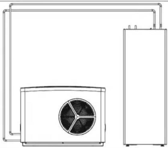
natural_image
Line drawing of a dual air conditioning unit with fan and cooling tower (no text or symbols)D0000080569
17.4 Energy consumption data
Product datasheet: DHW cylinder to Regulation (EU) No 812/2013 (S.I. 2019 No. 539 / Programme 2)
| HSBC 300 cool | ||
| 203801 | ||
| Manufacturer | STIEBEL ELTRON | |
| Supplier's model identifier | HSBC 300 cool | |
| Energy efficiency class | B | |
| Standby losses S | W | 61 |
| Cylinder capacity V | I | 291 |
17.5 Data table
| HSBC 300 cool | ||
| 203801 | ||
| Hydraulic data | ||
| Nominal capacity, DHW cylinder | l | 270 |
| Nominal capacity, buffer cylinder | l | 100 |
| Surface area, heat exchanger | m^2 | 3.20 |
| Capacity, heat exchanger | l | 21 |
| External available pressure differential, circulation pump, heat pump at 1.0 m^3/h | hPa | 656 |
| External available pressure differential, circulation pump, heat pump at 1.5 m^3/h | hPa | 527 |
| External available pressure differential, circulation pump, heat pump at 2.0 m^3/h | hPa | 210 |
| External available pressure differential, circulation pump, heating circuit 1 at 1.0 m^3/h | hPa | 725 |
| External available pressure differential, circulation pump, heating circuit 1 at 1.5 m^3/h | hPa | 663 |
| External available pressure differential, circulation pump, heating circuit 1 at 2.0 m^3/h | hPa | 444 |
| External available pressure differential, circulation pump, heating circuit 2 (optional) at 1.0 m^3/h | hPa | 665 |
| External available pressure differential, circulation pump, heating circuit 2 (optional) at 1.5 m^3/h | hPa | 518 |
| External available pressure differential, circulation pump, heating circuit 2 (optional) at 2.0 m^3/h | hPa | 189 |
| HSBC 300 cool | ||
| Application limits | ||
| Max. permissible pressure, DHW cylinder | MPa | 1.00 |
| Test pressure, DHW cylinder | MPa | 1.50 |
| Max. flow rate | l/min | 25 |
| Max. permissible pressure, buffer cylinder | MPa | 0.30 |
| Test pressure, buffer cylinder | MPa | 0.45 |
| Max. permissible temperature | °C | 85 |
| Max. permissible temperature, primary side | °C | 75 |
| Power consumption | ||
| Max. power consumption, charging pump | W | 60 |
| Max. power consumption, circulation pump, heating side | W | 60 |
| Energy data | ||
| Standby energy consumption/ 24 h at 65 °C | kWh | 1.50 |
| Energy efficiency class | B | |
| Electrical data | ||
| Rated voltage, control unit | V | 230 |
| Phases, control unit | 1/N/PE | |
| Control unit fuse protection | A | 1 x B 16 |
| Frequency | Hz | 50 |
| Versions | ||
| IP rating | IP20 | |
| Dimensions | ||
| Height | mm | 1918 |
| Width | mm | 680 |
| Depth | mm | 910 |
| Height when tilted | mm | 2123 |
| Weights | ||
| Weight of top section | kg | 176 |
| Weight of bottom section | kg | 56 |
| Weight, full | kg | 641 |
| Weight, empty | kg | 250 |
Further details
| HSBC 300 cool | ||
| 203801 | ||
| Maximum height for installation | m | 2000 |
17.5.1 Accessories
Pipe assembly RBS-SBC
| RBS-SBC238827 | ||
| Connections | ||
| Cold water connection | mm | 22 |
| DHW connection | mm | 22 |
| Connection, DHW circulation | mm | 12 |
| Versions | ||
| Suitable for | ...SBC 300 cool/plus, 300 L cool/plus, STI-D 270 | |
Pump assembly HSBC 3-HKM
| HSBC 3-HKM | ||
| 238825 | ||
| Connections | ||
| Connection, heating circuit | mm | 22 |
Guarantee
The guarantee conditions of our German companies do not apply to appliances acquired outside of Germany. In countries where our subsidiaries sell our products a guarantee can only be issued by those subsidiaries. Such guarantee is only granted if the subsidiary has issued its own terms of guarantee. No other guarantee will be granted.
We shall not provide any guarantee for appliances acquired in countries where we have no subsidiary to sell our products. This will not affect warranties issued by any importers.
Environment and recycling
▶ Dispose of the appliances and materials after use in accordance with national regulations.
If a crossed-out waste bin is pictured on the appliance, take the appliance to your local waste and recycling centre or nearest retail take-back point for reuse and recycling.
This document is made of recyclable paper.
- Dispose of the document at the end of the appliance's life cycle in accordance with national regulations.
REMARQUES PARTICULIÈRES
UTILISATION
1.1 Documentation applicable 61
1.1 Documentation applicable
text_image
Technical diagram of an electrical enclosure with labeled components and a magnified inset showing internal structure details.text_image
D0000102540 Made in GermanyINSTALLATION
7. Sécurité
natural_image
Diagram showing a ball suspended by strings above a sphere with a bolt inserted, illustrating mechanical motion (no text or symbols)natural_image
Technical line drawing of a rectangular electronic device with a directional arrow indicator (no text or symbols present)text_image
Exploded view diagram of an electrical enclosure with labeled components including casing, panel, and piping systemD0000101865
text_image
Technical diagram of an electrical cabinet with labeled components and directional arrows indicating assembly or connection.
natural_image
Technical diagram showing a mechanical assembly with a magnified inset highlighting a component (no text or symbols present)natural_image
Technical line drawing of a mechanical assembly with pipes and housing (no text or symbols)text_image
Technical diagram showing a computer tower with labeled components and a magnified view of the interior panel detail.
natural_image
Cross-sectional diagram of a mechanical assembly with internal components and directional arrows (no text or symbols)natural_image
Technical line drawing of a mechanical assembly with pipes and control panel (no text or symbols)▶ Retirez les 4 flexibles hydrauliques.
▶ Retirez les 2 vis pour isolant.
▶ Retirez l'élément isolant 3.

natural_image
Technical diagram of an internal device with labeled ports and connectors (no readable text or symbols)natural_image
Technical line drawing of an industrial machine or control unit with multiple ports and mounting brackets (no text or symbols visible)natural_image
3D diagram of a mechanical component with a block and a top section, showing an arrow indicating direction (no text or symbols present)natural_image
Technical diagram of an electronic device showing internal components and a base housing (no text or symbols present)natural_image
Technical line drawing of an internal electrical enclosure or enclosure with visible components and wiring (no text or symbols)text_image
Technical diagram of a device rear panel with labeled components and an inset close-up showing internal structure.natural_image
Technical line drawing of a mechanical component with curved and rectangular features (no text or symbols)natural_image
3D diagram of a mechanical component with a black arrow indicating direction, no text or symbols presenttext_image
Technical diagram of a wall-mounted electrical switch assembly with numbered componentstext_image
Technical diagram of an electronic device with numbered components and a highlighted internal mechanismtext_image
Technical diagram illustrating mechanical assembly steps with labeled components and warning indicatorsnatural_image
Technical line drawing of a mechanical assembly with an inset close-up showing internal components (no text or symbols)text_image
Technical diagram of a device interior with labeled components and a circular cross-section viewnatural_image
Technical line drawing of an electronic device showing internal components and mounting brackets (no text or symbols)natural_image
Technical diagram showing a mechanical component with an inset close-up of a circular component, no visible text or symbols.natural_image
Technical line drawing of a mechanical or electrical component with pipes and housing (no visible text or symbols)Régime constant (I, II, III)
text_image
Diagram showing icons and labels for a system or application, including symbols like '绘图', '绘图' with arrows and numbers 3 and 10.natural_image
Technical line drawing of a mechanical assembly with an inset close-up showing a circular component detail (no text or symbols)flowchart
graph TD
    A["HSBC 3-HE (Zubehör) (X2.11)"] --> B["XD06.1"]
    A --> C["XE01"]
    B --> D["Deckelblech/Top cover"]
    C --> E["Steuerspannung XD03.1"]
    D --> F["Vorderwand/Front cover"]
    E --> G["Steuerspannung XD03.1"]
    H["KA 17"] --> I["MA15"]
    I --> J["MA19"]
    K["Steuerspannung XD03.1"] --> L["GNYE BN BU"]
    L --> M["M 1~"]
    M --> N["BU (com)"]
    M --> O["BN (PWM IN)"]
    P["Steuerspannung XD03.1"] --> Q["MA14"]
    Q --> R["GNYE BU BN"]
    R --> S["N L"]
    S --> T["M 1~"]
    T --> U["MA10"]
    U --> V["GNYE BU BN"]
    V --> W["N L"]
    W --> X["M 1~"]
    X --> Y["MA11"]
    Y --> Z["GNYE BU BN"]
    Z --> AA["N L"]
    AA --> AB["M 1~"]
    AB --> AC["MA10"]
    AC --> AD["GNYE BU BN"]
    AD --> AE["N L"]
    AE --> AF["M 1~"]
    AF --> AG["MA11"]
    AG --> AH["GNYE BU BN"]
    AH --> AI["N L"]
    AI --> AJ["M 1~"]
    AJ --> AK["MA10"]
    AK --> AL["GNYE BU BN"]
    AL --> AM["N L"]
    AM --> AN["M 1~"]
    AN --> AO["GNYE BU BN"]
    AO --> AP["N L"]
    AP --> AQ["M 1~"]
    AQ --> AR["GNYE BU BN"]
    AR --> AS["N L"]
    AS --> AT["M 1~"]
    AT --> AU["GNYE BU BN"]
    AU --> AV["N L"]
    AV --> AW["M 1~"]
    AW --> AX["GNYE BU BN"]
    AX --> AY["N L"]
    AY --> AZ["M 1~"]
    AZ --> BA["GNYE BU BN"]
    BA --> BB["N L"]
    BB --> BC["M 1~"]
    BC --> BD["GNYE BU BN"]
    BD --> BE["N L"]
    BE --> BF["M 1~"]
    BF --> BG["GNYE BU BN"]
    BG --> BH["N L"]
    BH --> BI["M 1~"]
    BI --> BJ["GNYE BU BN"]
D0000093952
flowchart
graph TD
    subgraph Power Supply
        A["CAN A"] --> B["X1.19"]
        C["CAN B"] --> D["X1.18"]
        E["CAN A"] --> F["X1.17"]
        G["CAN B"] --> H["X1.16"]
        I["XAN"] --> J["X1.15"]
        K["CAN A"] --> L["X1.14"]
        M["CAN B"] --> N["X1.13"]
        O["CAN A"] --> P["X1.12"]
        Q["XAN"] --> R["X1.10"]
        S["CAN B"] --> T["X1.9"]
        U["XAN"] --> V["X1.8"]
        W["XAN"] --> X["X1.7"]
        Y["XAN"] --> Z["X1.6"]
        AA["XAN"] --> AB["X1.5"]
        AC["XAN"] --> AD["X1.4"]
        AE["XAN"] --> AF["X1.3"]
        AG["XAN"] --> AH["X1.2"]
        AI["XAN"] --> AJ["X1.1"]
    end

    subgraph Power Supply
        AK["BU (com.)"]
        AL["BN (PWM IN)"]
        AM["BT08"]
        AN["BT20"]
        AO["BT13"]
        AP["BT06"]
        AQ["BT30"]
        AR["BUS"]
        AS["X14"]
        AT["AA13"]
    end

    subgraph Power Supply
        AU["X27"]
        AV["AA06"]
        AW["AA16 (ISG)"]
    end

    style Power Supply fill:#f9f,stroke:#333
    style Bus fill:#ccf,stroke:#333
    style Power Supply fill:#cfc,stroke:#333
D0000093952
natural_image
Technical line drawing of a dual air conditioning unit with fan and cooling tower (no text or symbols)D0000080569
WAARSCHUWING verbranding
text_image
Technical diagram of an electrical enclosure with labeled components and a magnified inset showing internal components.1 wit = anode ok
2 rood = controle door installateur vereist
6. Problemen verhelpen
text_image
D0000102540 Made in GermanyINSTALLATIE
7. Veiligheid
natural_image
Diagram showing a ball suspended by strings above a sphere with a bolt inserted, illustrating mechanical motion (no text or symbols)natural_image
Technical line drawing of a rectangular electronic device with a black arrow indicating a directional flow (no text or symbols present)text_image
Exploded view diagram of an electrical enclosure with labeled components including casing, panel, and air duct systemD0000101865
text_image
Technical diagram of an electrical cabinet with labeled components and directional arrows indicating assembly or movement.
natural_image
Technical diagram showing a mechanical assembly with a magnified inset highlighting a component (no text or symbols present)natural_image
Technical line drawing of a mechanical assembly with pipes and housing (no text or symbols)text_image
Technical diagram showing a computer tower with labeled components and a magnified view of the door handle mechanism.
natural_image
Cross-sectional diagram of a mechanical assembly with internal components and directional arrows (no text or symbols)natural_image
Technical line drawing of a mechanical assembly with pipes and housing (no text or symbols)natural_image
Technical diagram of an internal device with labeled ports and connectors (no readable text or symbols)natural_image
Technical line drawing of an industrial machine or control unit with multiple ports and mounting brackets (no text or symbols visible)natural_image
3D diagram of a mechanical component with a highlighted section and an arrow indicating direction (no text or symbols)natural_image
Technical diagram of an electronic device showing internal components and a base case with mounting holes (no text or symbols present)natural_image
Technical line drawing of an electrical enclosure with internal components (no text or symbols)text_image
Technical diagram of an electronic device with labeled components and a magnified inset showing internal structure details.natural_image
Technical line drawing of a mechanical component with curved and rectangular features, no visible text or symbolsnatural_image
3D diagram of a mechanical component with an arrow indicating direction, no text or symbols presenttext_image
Technical diagram of a wall-mounted air conditioner unit with numbered components and labeled partstext_image
Technical diagram of an electronic device with numbered components and a highlighted internal mechanismtext_image
Technical diagram illustrating mechanical assembly steps with labeled components and safety warning indicatorsnatural_image
Technical line drawing of a mechanical assembly with an inset close-up showing a circular component detail (no text or symbols)text_image
Technical diagram of a mechanical device with labeled components and a circular inset view showing internal structure.natural_image
Technical line drawing of an electronic device showing internal components and mounting brackets (no text or symbols)natural_image
Technical diagram showing a mechanical component with an inset close-up of a circular component, no visible text or symbols.▶ Steek de temperatuursensor in de sensorhuls "Sensor WP koelen optioneel".
natural_image
Technical line drawing of a mechanical device with pipes and housing (no text or symbols)natural_image
Technical line drawing of a mechanical assembly with an inset close-up showing a circular component detail (no text or symbols)▶ Tap het buffervat af via de aftapkraan.
Warmwaterboiler aftappen

natural_image
Technical line drawing of a dual air conditioning unit with fan and cooling tower (no text or symbols)D0000080569
text_image
Technical diagram of an electrical enclosure with labeled components and a magnified inset showing internal structure.text_image
D0000102540 Made in GermanyINSTALLAZIONE
7. Sicurezza
natural_image
Technical diagram showing a mechanical assembly with a bolt and a magnified inset (no text or symbols)natural_image
Technical line drawing of a rectangular electronic device with a black arrow indicating a directional flow (no text or symbols present)text_image
Exploded view diagram of an electronic device showing internal components and labeled partsD0000101865
1 Elemento isolante 1
2 Elemento isolante 2
text_image
Technical diagram of an electrical cabinet with labeled components and directional arrows indicating assembly or connection.
text_image
Technical diagram showing mechanical assembly with labeled components and a magnified inset view of a component being inserted.natural_image
Technical line drawing of a mechanical assembly with pipes and housing (no text or symbols)text_image
Technical diagram showing a device rear panel with labeled ports and an inset close-up of the handle, alongside a 3D geometric model.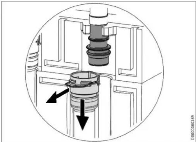
natural_image
Cross-sectional diagram of a mechanical assembly with internal components and directional arrows (no text or symbols)natural_image
Technical line drawing of a mechanical assembly with pipes and control panel (no text or symbols)natural_image
Technical diagram of an internal device with labeled ports and connectors (no readable text or symbols)natural_image
Technical line drawing of an electrical cabinet or enclosure with internal components and mounting holes (no text or symbols)natural_image
3D diagram of a mechanical component with a left-pointing arrow, no text or symbols presentnatural_image
Technical diagram of an electronic device showing internal components and a base housing (no text or symbols present)natural_image
Technical line drawing of an electrical enclosure with internal components and wiring (no text or symbols)text_image
Technical diagram of an electronic device with labeled components and a magnified inset showing internal components.natural_image
Technical line drawing of a mechanical component with curved and flat surfaces, no visible text or symbolsnatural_image
3D diagram of a mechanical component with an arrow indicating direction, no text or symbols presenttext_image
Technical diagram of a wall-mounted air conditioner unit with numbered components and labeled partstext_image
Technical diagram of an electronic device with numbered components and a highlighted internal mechanismtext_image
Technical diagram illustrating mechanical assembly steps with labeled components and warning indicatorstext_image
Technical diagram of an electronic device layout with labeled components and connection linesDanni materiali
natural_image
Technical line drawing of a mechanical assembly with an inset close-up showing internal components (no text or symbols)text_image
Technical diagram of an electrical enclosure with labeled components and a magnified view showing internal wiring or wiring connections.natural_image
Technical line drawing of an electronic device showing internal components and mounting brackets (no text or symbols)natural_image
Technical diagram showing a mechanical component with an inset close-up of a circular component and a curved tool (no text or symbols present)natural_image
Technical line drawing of a mechanical assembly with pipes and housing (no text or symbols)text_image
Diagram showing icons and symbols for document editing, navigation, and settings with arrows and numbers 3 and 10.natural_image
Technical line drawing of a mechanical assembly with an inset close-up showing internal components (no text or symbols)natural_image
Technical line drawing of a dual air conditioning unit with fan and cooling unit (no text or symbols)D0000080569