
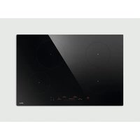
NikolaTesla Flame BLA88 - Cooker ELICA - Free user manual and instructions
Find the device manual for free NikolaTesla Flame BLA88 ELICA in PDF.
| Brand | Elica |
| Model | NikolaTesla Flame BLA88 |
| Product Type | Gas hob with integrated hood |
| Number of Burners | 4 (2 semi-rapid, 1 rapid, 1 Dual) |
| Gas Supply | Natural gas G20/G25.3, LPG G30 (depending on adjustment) |
| Nominal Gas Pressure | 20 mbar (G20), 25 mbar (G25.3), 29/50 mbar (G30) |
| Dual Burner Power (outer + inner) | 2.7 kW + 0.8 kW |
| Rapid Burner Power | 3.0 kW |
| Semi-rapid Burner Power (x2) | 1.75 kW each |
| Electrical Supply | 230 V ~ 50 Hz |
| Type of Installation | Built-in (class 3) |
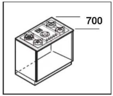
| Cut-out Dimensions (W x D) | Approx. 75-85 cm x 50-55 cm (according to manual) |
| Worktop Thickness | 2-6 cm (TOP installation), 2.5-6 cm (FLUSH) |
| Minimum Side Distance | 40 cm from each side |
| Minimum Back Distance | 5 cm from wall |
| Minimum Above Distance | 50 cm from overhead units |
| Ignition | Electronic spark ignition |
| Safety | Thermocouple on all burners, automatic shut-off in case of flame failure |
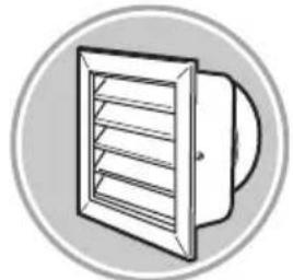
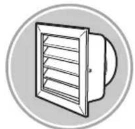
| Integrated Hood | Yes, extraction or recirculation |
| Suction Speeds | 5 (including 2 timed Boost speeds) |
| Hood Timer | Yes (15, 10 or 5 minutes depending on speed) |
| Filter Saturation Indicator | Yes (LED) |
| Grease Filter | Washable metal (monthly) |
| Active Charcoal Filter | Non-washable, to be replaced (recirculation version) |
| Surface Material | Glass |
| Weight (approx.) | Approx. 30 kg |
Frequently Asked Questions - NikolaTesla Flame BLA88 ELICA
User questions about NikolaTesla Flame BLA88 ELICA
0 question about this device. Answer the ones you know or ask your own.
Ask a new question about this device
Download the instructions for your Cooker in PDF format for free! Find your manual NikolaTesla Flame BLA88 - ELICA and take your electronic device back in hand. On this page are published all the documents necessary for the use of your device. NikolaTesla Flame BLA88 by ELICA.
USER MANUAL NikolaTesla Flame BLA88 ELICA
EN Instruction on mounting and use
natural_image
Technical line drawing of a mechanical component with multiple ports and mounting base (no text or symbols)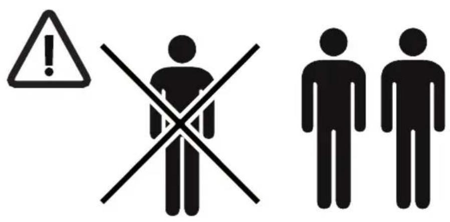

natural_image
Simple line icon of a house with an upward arrow, enclosed in a gray circle (no text or symbols)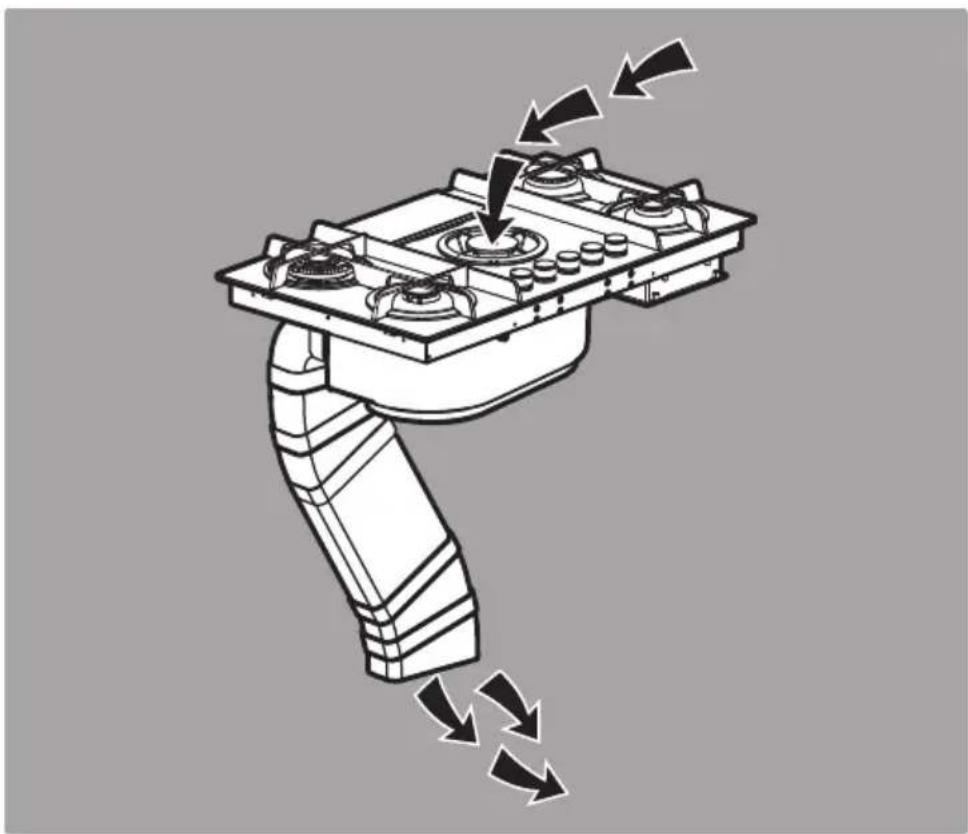
natural_image
Mechanical robotic arm with directional arrows indicating motion or force (no text or symbols)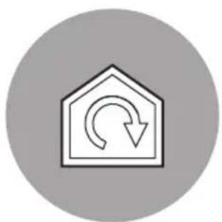
natural_image
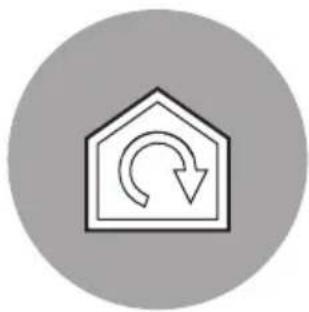
Simple house icon with curved arrow inside, enclosed in a gray circle (no text or symbols)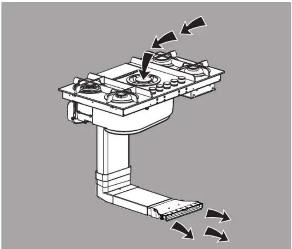
natural_image
Technical illustration of a robotic arm with four stoves and directional arrows indicating motion (no text or symbols)
natural_image
Illustration of a stylized figure holding a magnifying glass, enclosed in a circle with an exclamation mark (no text or symbols on the figure itself)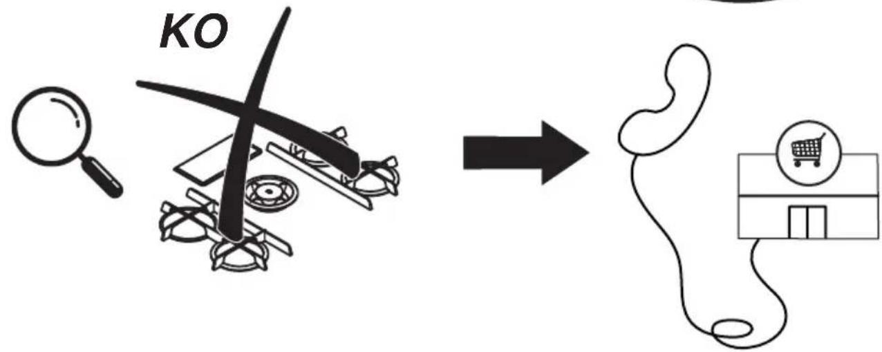
flowchart
graph LR
    A["MO"] --> B["Arrow"]
    B --> C["Shopping Cart Icon"]
2x

1 x
2,8 m

6x


6x

6 x

4x
1x
natural_image
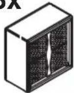
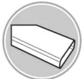
Isometric line drawing of a 3D rectangular prism with internal structural framework (no text or symbols)1x
1x
1x
natural_image
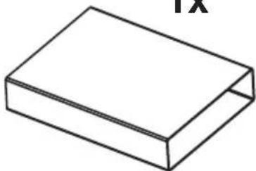
Simple line drawing of a 3D rectangular prism (no text or symbols)1x

4x
natural_image
Line drawing of a 3D rectangular prism or container (no text or symbols)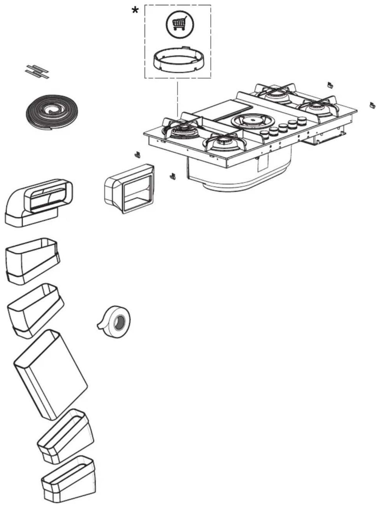
2x


6x


6 x

6 x

1 x
natural_image
Circular object with concentric rings, labeled '2,8 m' at bottom (no other text or symbols)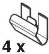
1x
natural_image
Simple line drawing of a 3D rectangular prism with no text or symbols2x
2x

1x
natural_image
Isometric line drawing of a 3D rectangular prism with no text or symbols1x

natural_image
Technical line drawing of a mechanical component with no visible text or symbols
natural_image
Technical line drawing of a mechanical structure with no visible text or symbols1x
3x
1x
1x
natural_image
Simple line drawing of a rectangular box (no text or symbols)1x
natural_image
Technical line drawing of a mechanical housing or enclosure with internal compartments and mounting holes (no text or symbols)*
natural_image
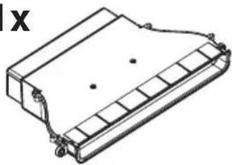
Exploded view diagram of a gas stove assembly showing internal components and parts (no text or labels)


2a.1
inst.A
natural_image
Circular object with spiral pattern, labeled with 1 x and 2.8 m (no other text or symbols)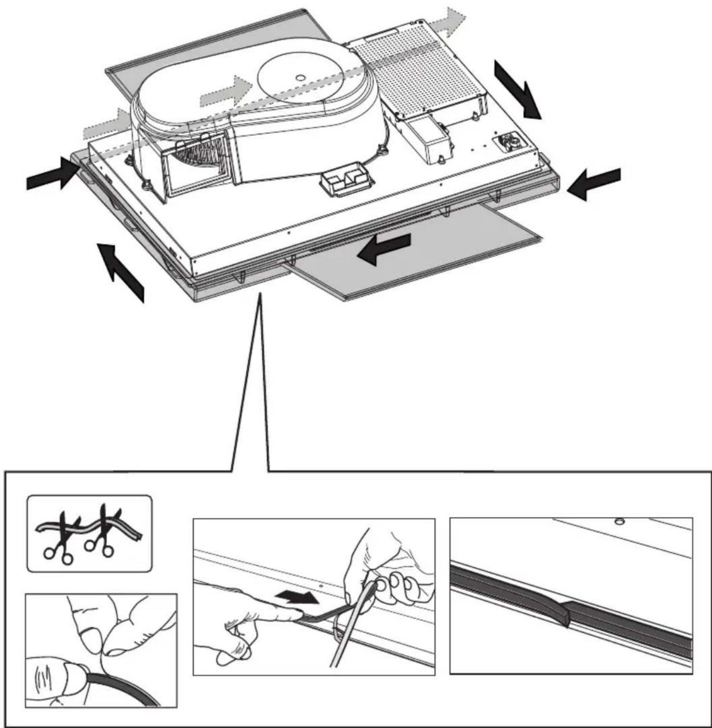
2a.2

220V-240V \~ 50Hz
3
4
natural_image
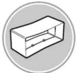
Isometric line drawing of a rectangular box with internal compartments and directional arrows indicating flow or movement (no text or symbols)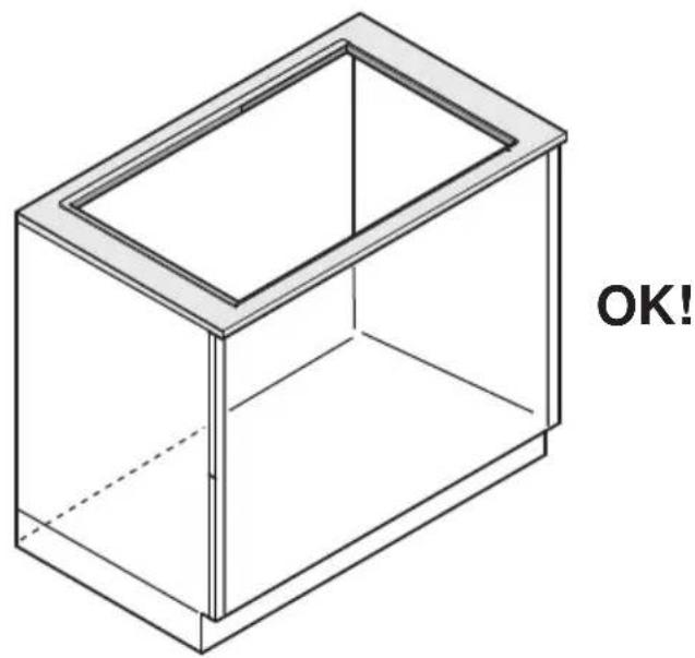
natural_image
Isometric line drawing of a 3D rectangular box with a dashed internal line and 'OK!' text on the right side (no other text or symbols)
natural_image
Technical line drawing of a mechanical component with a 4x label (no other text or symbols)
natural_image
Technical line drawing of a mechanical component with multiple circular features and mounting brackets (no text or symbols)
inst.B

flowchart
graph TD
    A["Top-Down Arrow"] --> B["Arrow Down"]
    B --> C["Bottom-Down Arrow"]
natural_image
Simple line icon of a house with an upward arrow, enclosed in a gray circle (no text or symbols)
natural_image
Technical line drawing of a robotic arm with directional arrows indicating motion or force (no text or symbols)
7a.2

7a.2
7a.3
7a.4

www.elica.com www.shop.elica.com

www.elica.com www.shop.elica.com
natural_image
Technical line drawing of a battery cell with internal components (no text or symbols)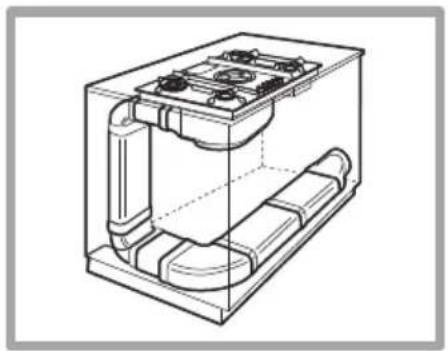
natural_image
Technical line drawing of a mechanical device with internal components and mounting holes (no text or symbols)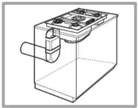
natural_image
Technical line drawing of a mechanical device with a housing and internal components (no text or symbols)KIT0121007
natural_image
Simple line drawing of a bolt with threaded base, enclosed in a circular frame (no text or symbols)227x94 - ∅146mm
KIT0120996
natural_image
Simple line drawing of a cylinder inside a circular frame (no text or symbols)∅150x500mm
KIT0121000
natural_image
Simple line drawing of a cylinder inside a circular frame (no text or symbols)∅150x1000mm
KIT0121003
natural_image
Simple line drawing of a cylindrical object inside a circular frame (no text or symbols)∅158x59mm
KIT0121006
natural_image
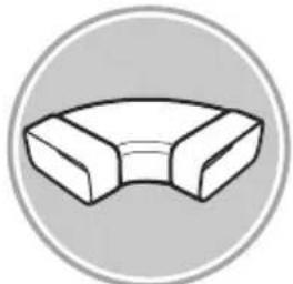
Simple line drawing of a cylindrical object with a flanged end, enclosed in a circular frame (no text or symbols)90°
KIT0120991
natural_image
Simple 3D illustration of a rectangular block inside a circular frame (no text or symbols)222x89x1000mm
KIT0121001
natural_image
Simple line drawing of a rectangular electronic component with two pins, enclosed in a circular frame (no text or symbols)227x94x80mm
KIT0121004
natural_image
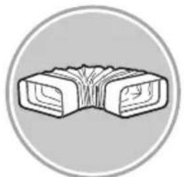
Simple 3D geometric shape resembling a curved bracket or pipe, enclosed in a circular frame (no text or symbols)90° 227x288x94mm
KIT0121005
natural_image
Simple line drawing of a rectangular object inside a circular frame (no text or symbols)90° 227x94mm
KIT0121008
natural_image
Simple line drawing of a pipe fitting (no text or symbols)227x94 - ∅153mm
KIT0121010
natural_image
Simple line drawing of a ventilation duct inside a circular frame (no text or symbols)190x190 - ∅147mm
KIT0121009
natural_image
Simple line drawing of a ventilation duct inside a circular frame (no text or symbols)INT 216X82mm
EXT 290X160mm
natural_image
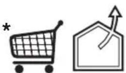
Two simple line icons: a shopping cart with an asterisk and a house with an upward arrow (no text or symbols)www.elica.com
www.shop.elica.com
KIT0121002
natural_image
Simple line drawing of a rectangular object inside a circular frame (no text or symbols)15° - 227x94mm
KIT0126810
natural_image
Simple line drawing of a folded paper or scroll inside a circular frame (no text or symbols)227x94mm
natural_image
Simple house icon with curved arrow inside, enclosed in a hexagon (no text or symbols)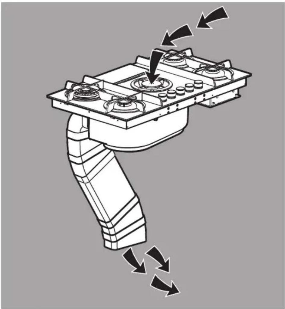
natural_image
Mechanical robotic arm with valve mechanism and directional arrows indicating motion (no text or symbols)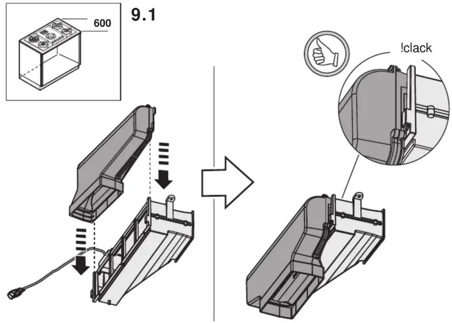
9a.1.2
9a.1.3
natural_image
Diagram showing two mechanical components with arrows indicating assembly or connection, no text or symbols present.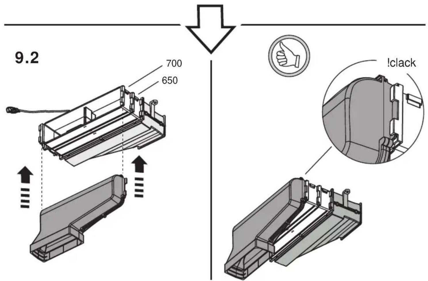
9.3
natural_image
Technical line drawing of a rectangular enclosure with two zoomed-in insets showing internal components (no text or symbols)9.5
X ≥18,5mm ≤ 22,5mm
natural_image
Technical line drawing of a device housing with internal components and a close-up view showing internal structure (no text or symbols)11.2b
natural_image
Technical line drawing of a mechanical device with a handle and mounting base (no text or symbols)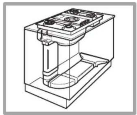
natural_image
Technical line drawing of a mechanical device with internal components (no text or symbols)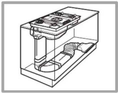
natural_image
Technical line drawing of a mechanical device with internal components (no text or symbols)KIT0121012
natural_image
Simple 3D illustration of a rectangular block inside a circular frame (no text or symbols)218X55X500mm
KIT0121013
natural_image
Simple 3D illustration of a rectangular block inside a circular frame (no text or symbols)218X55X1000mm
KIT0121015
natural_image
Simple line drawing of a rectangular box with internal lines and two dots, enclosed in a circular frame (no text or symbols)218X55X70mm
KIT0121016
natural_image
Simple 3D geometric shape resembling a bent pipe or elbow bracket, enclosed in a circular frame (no text or symbols)90° 218X55mm
KIT0121017

natural_image
Illustration of a rectangular rock or mineral sample with vertical striations, enclosed in a circular frame (no text or symbols)218x55mm
KIT0126810
natural_image
Simple line drawing of a folded paper or seal with no text or symbols227x94mm
KIT0121002
natural_image
Simple line drawing of a rectangular object inside a circular frame (no text or symbols)15° - 227x94mm
KIT0121005
natural_image
Simple line drawing of a rectangular object with a rounded base, enclosed in a circular frame (no text or symbols)90° 227x94mm
KIT0140820

www.elica.com
www.shop.elica.com
natural_image
Simple line drawing of a mechanical component inside a circular frame (no text or symbols)KIT0130427
natural_image
Simple 3D geometric shape resembling a folded corner or bracket, enclosed in a circular frame (no text or symbols)
natural_image
Simple icon of a house inside a circle with a curved arrow indicating rotation (no text or symbols)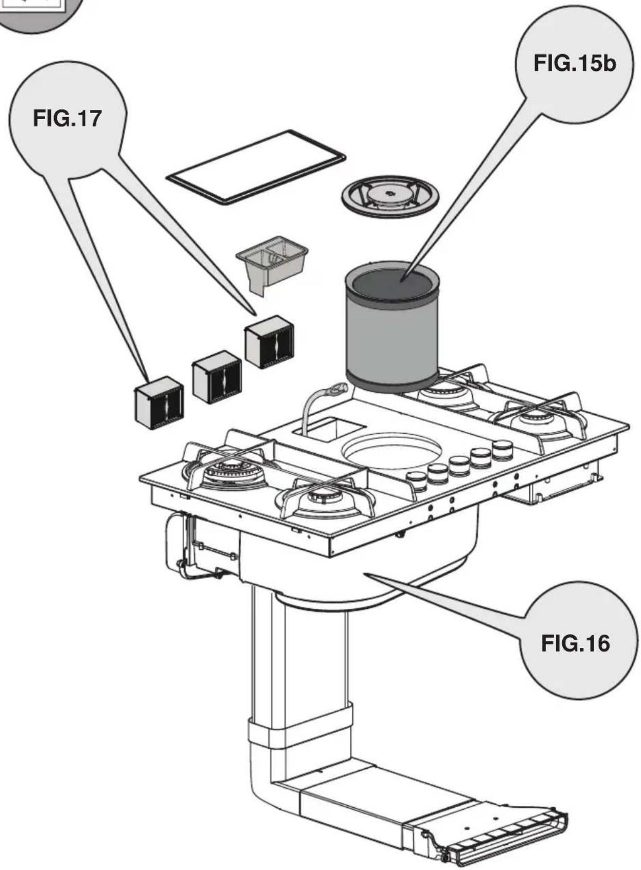
flowchart
graph TD
    A["Top Component"] --> B["Box"]
    B --> C["Container"]
    C --> D["Cylinder"]
    D --> E["Order Box"]
    E --> F["Shake Box"]
    F --> G["Shake Tank"]
    G --> H["Shake Sink"]
    H --> I["Shake Plate"]
    I --> J["Shake Board"]
    J --> K["Shake Panel"]
    K --> L["Shake Column"]
    L --> M["Shake Shelf"]
    M --> N["Shake Floor"]
    N --> O["Shake Window"]
    O --> P["Shake Deck"]
    P --> Q["Shake Deck"]
    Q --> R["Shake Deck"]
    R --> S["Shake Deck"]
    S --> T["Shake Deck"]
    T --> U["Shake Deck"]
    U --> V["Shake Deck"]
    V --> W["Shake Deck"]
    W --> X["Shake Deck"]
natural_image
Simple icon of a house with a circular arrow and curved arrow inside, no text or symbols present.
flowchart
graph TD
    A["Assembly Module"] --> B["Product"]
    B --> C["Assembly Unit"]
    C --> D["Product"]
    D --> E["Product"]
    E --> F["Product"]
    F --> G["Product"]
    G --> H["Product"]
    H --> I["Product"]
    I --> J["Product"]
    J --> K["Product"]
    K --> L["Product"]
    L --> M["Product"]
    M --> N["Product"]
    N --> O["Product"]
    O --> P["Product"]
    P --> Q["Product"]
    Q --> R["Product"]
    R --> S["Product"]
    S --> T["Product"]
    T --> U["Product"]
    U --> V["Product"]
    V --> W["Product"]
    W --> X["Product"]
    X --> Y["Product"]
    Y --> Z["Product"]
natural_image
Technical line drawing of a mechanical assembly with a housing and connecting rod (no text or symbols)
natural_image
Illustration of a cooking pot on a gas stove with steam rising (no text or symbols)natural_image
Mechanical assembly diagram showing a circular component with labeled parts (a and b), no readable text or symbols present.a. DISPOSITIVO DI SICUREZZA
EN - Instruction on mounting and use
Strictly observe the instructions in this manual. All liability is declined for any problems, damage or fires caused by failure to comply with the instructions in this manual. The device is intended for domestic use only, to cook food and extract the fumes generated by cooking. No other use is allowed (e.g. heating rooms). The manufacturer declines any liability for inappropriate use or incorrect control settings. The device may have different aesthetic features with respect to the illustrations in this handbook, however the operating, maintenance and installation instructions remain the same.
Read the instructions carefully: they include important information about installation, use and safety.
Do not make electrical changes to the device.
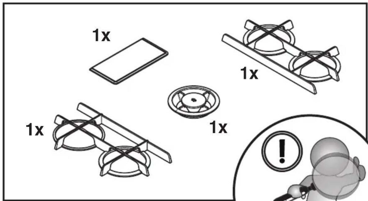
Before installing the device, make sure that none of the components are damaged. Otherwise, contact the dealer and do not continue with the installation.
Check that the device is intact before continuing with installation. Otherwise, contact the dealer and do not continue with the installation.
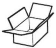
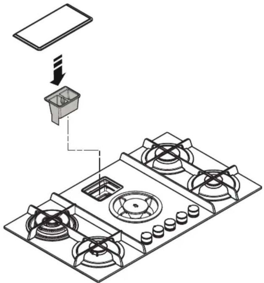
Note: The parts marked with the symbol "(*)" are optional accessories supplied only with some models or otherwise not supplied, but available for purchase.
1. Warnings
Warning! Strictly observe the following instructions: ● Before installation, make sure that the local distribution conditions (the gas type and pressure) and equipment adjustment are compatible. ● The device must be installed and connected in compliance with current installation regulations in the country of destination/use. Special precautions must be taken with respect to ventilation requirements of the premises in which the device to be installed. ● This device is a class 3 recessed device. ● The instructions are only valid for countries whose symbols are indicated on the serial number plate. ● The device is intended for non-professional use in the home. ● Do not allow the power cable for the device in question and for other
electrical appliances to come into contact with the hot surfaces. ● Do not obstruct the openings for ventilation and heat dispersion. ● In the event of a fault, never access the internal mechanisms to try to repair them. Contact technical support. ● Make sure that the handles of pans are always facing towards the inside of the hob to avoid accidentally knocking them. ● Do not use unstable or deformed pans. ● The device must be disconnected from the electrical supply before performing any installation work. ● If the power cable is damaged, it must be replaced by the manufacturer or by the authorised technical support service or by a technician with a similar qualification to avoid any risks. ● Installation or maintenance must be performed by a qualified technician, in compliance with the manufacturer's instructions and local safety regulations. Do not repair or replace any part of the device unless specifically stated in the operating manual. ● Earthing the device is compulsory. ● In order for the installation to comply with current safety regulations, a compliant omnipolar switch is required that guarantees the complete disconnection of the mains in category III overvoltage conditions, in accordance with the installation rules. ● Do not use power strips or extension cords. ● Once installation is complete, the electrical components must no longer be accessible by the user. ● The device and its accessible parts get hot during use.
Be careful not to touch the heating elements. ● Ensure that children do not play with the device; keep children away and supervise them, as the accessible parts may become very hot during use. ● During and after use, do not touch the heating elements of the device. ● Avoid contact with kitchen towels or other flammable materials until all components of the device have sufficiently cooled. ● Do not place flammable materials on or near the device. ● Overheated fats and oils easily catch fire. Take extra care when cooking food rich in fat and oil. ● If the surface is cracked, switch off the device to avoid the possibility of an electric shock. ● The device is not intended to be run with an external timer or a separate remote control system. ● The cooking process must be supervised. ● NEVER attempt to put fires out using water. Instead, turn off the device and smother the flames, for example with a lid or a fire blanket. Fire hazard: do not rest objects on the cooking surfaces. ● Do not use steam cleaners. ● Before connecting the device to the electrical network: check the data plate (on the bottom of the device) to ensure that the voltage and power correspond to the network values and that the connection socket is suitable. If in doubt, consult a qualified electrician.
Important: • After use, turn off the hob with the control device. • To prevent liquids from boiling over, reduce the heat. • Do not leave the heating elements on with empty pots and pans or with no pans. • Once cooking is complete, turn off the relevant zone. • Never leave empty pans on the hot elements when switched on. • Do not use pans which protrude over the edges of the top. • WARNING! If the glass top breaks: • 1) immediately turn off all the burners and disconnect the power supply. • 2) do not touch the surface of the device • 3) do not use the device. • WARNING! Using the gas top produces heat, humidity and combustion products in the room in which it is installed. Make sure that the room is well ventilated, especially when the device is in use. Keep the ventilation openings open or install a mechanical fan. • Prolonged and intensive use of the device may require additional ventilation (e.g. opening a window) or more efficient ventilation (e.g. increasing the level of mechanical fan when present). •
WARNING! The device is designed exclusively for domestic use for cooking food. No other use is allowed (e.g. heating rooms). • Never heat a tin or can containing foods without opening it first: it might explode! • The containers must be placed directly on the hob and should be centred. Under no circumstances may any other objects be inserted between the pan and the hob. • When used, the device produces heat and humidity in the room in which it is installed. Make sure the kitchen is adequately ventilated; keep the ventilation openings open as required by current laws. • Prolonged use of the device may require additional ventilation, for example, opening a window. • If after 15 seconds, the burner does not ignite, open the door of the room and wait at
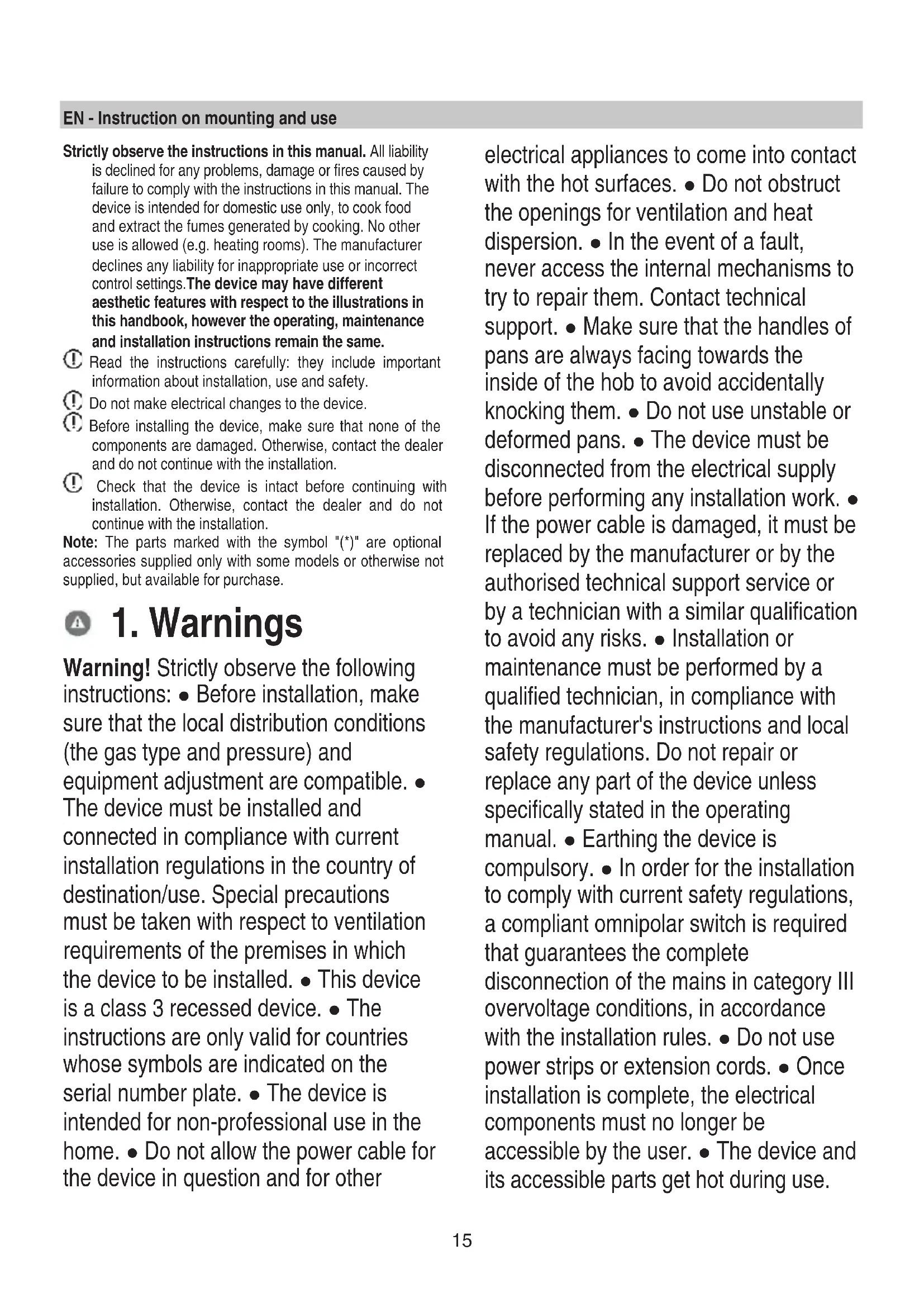
least one minute before trying again. On tops with no safety mechanism, if the flames go out, close the relevant tap and do not attempt to relight the stove for one minute. After cooking, it is advisable to close the main gas tap and/or cylinder. Before performing any cleaning or maintenance work, disconnect the product from the electrical power supply by removing the plug or disconnecting the master switch. For all installation and maintenance operations, always use work gloves. The device can be used by children 8 years or older and by persons with physical, sensory or mental impairments, or by people without any experience or the necessary knowledge, provided they are supervised or have received instructions regarding the safe use of the device and provided they have a thorough understanding of the associated risks. Children must be supervised to ensure they do not play with the device. Cleaning and maintenance must never be performed by children unless they are properly supervised. Children under the age of 8 must be kept away from the device. Children must not play with the device. The room must be properly ventilated when the cooker hood is used at the same time as other combustion devices, gas or otherwise. The hood must be regularly cleaned both internally and externally (AT LEAST ONCE PER MONTH), in strict accordance with the maintenance instructions. Failure to follow the rules for hood cleaning and filter replacement and cleaning shall result in a fire hazard. ● It is strictly prohibited to cook food directly with the flame. ● The use of an open flame may damage the filters and cause a fire hazard; it must therefore be avoided under all circumstances. ● Extra care must be taken when frying to prevent the oil from overheating and catching fire. ● WARNING: When the hob is on, the accessible parts of the hood may become hot. ● Warning! Do not connect the device to the electrical network until installation is entirely complete. ● In regards to the technical and safety measures that must be adopted for fume extraction, regulations issued by local authorities must be strictly followed. ● The extracted air must not be conveyed through the same ducts used to extract the fumes generated by gas combustion or other types of combustion devices. ● Never use the hood unless the grill has been correctly assembled! ● Use only the fastening screws supplied with the product for its installation, or if not supplied, purchase the correct type of screws. Use screws with the right length, as indicated in the installation guide. ● When the cooker hood is used together with other devices powered with non-electrical energy, the negative pressure of the room must not exceed 4 Pa (4 x 10⁻⁵ bar). This device is marked in compliance with the European Directive 2012/19/EC - UK SI 2013 No3113, Waste Electrical and Electronic Equipment (WEEE). By ensuring that this device is disposed of correctly, the user will help prevent potential negative impacts on the environment and
human health. The symbol
on the product or
accompanying documentation indicates that this product should not be treated as household waste but should be handed over at a suitable collection point for the recycling of electrical and electronic equipment. Dispose of the device in accordance with local regulations on waste disposal. For further information about the treatment, recovery and recycling of this product, please contact your local authority, a collection service for household waste or the shop where the product was purchased.
Device designed, tested and developed in compliance with regulations on:
- Safety: EN/IEC 60335-1; EN/IEC 60335-2-102, EN/IEC 60335-2-31, EN/IEC 62233, EN30-1.
• Performance: EN/IEC 61591; ISO 5167-1; ISO 5167-3; ISO 5168; EN/IEC 60704-1; EN/IEC 60704-2-13; EN/IEC 60704-3; ISO 3741; EN 50564; IEC 62301; EN30-2-1. - EMC: EN 55014-1; CISPR 14-1; EN 55014-2; CISPR 14-2; EN/IEC 61000-3-3; EN/IEC 61000-3-12. Recommendations for correct use in order to reduce the impact on the environment: When you start cooking, turn the device on at minimum speed, leaving it on for a few minutes when you have finished cooking. Increase the speed only if there is a large quantity of fumes and steam, using the Booster function only in extreme cases. To keep the odour reduction system running efficiently, replace the carbon filter/s when necessary.
To ensure the high performance of the grease filter, clean it when necessary. To improve efficiency and minimise noise, use the maximum duct diameter indicated in this manual.
2. Use
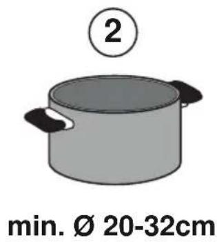
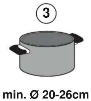
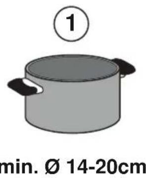
2.2 Energy saving
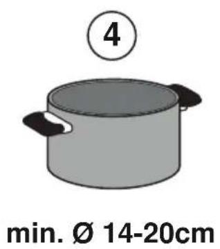
NB = use pans with a suitable diameter for the burners and make sure the highest flame does not protrude from under them
Recommendations for best results:
- Use pots and pans with a base diameter suitable for the size of the burners.
To see the diameter of the pan to use on each individual burner, consult the relevant section in this manual.
- Use only pots and pans with flat bottoms.
- Where possible, keep the lid on pots during cooking
- Cook vegetables, potatoes, etc. with a minimal amount of water to reduce cooking time.
- Use a pressure cooker, as it further reduces the energy consumption and cooking time
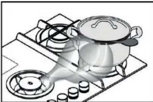
- Place the pot in the centre of the cooking zone drawn on the hob.
- To reduce power consumption, the burners should be adjusted to suit the cooking under way. For best extraction of vapours, place a ladle between the lid and the pot, in particular in the case of tall pots.
natural_image
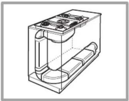
Illustration of a cooking pot on a gas stove with steam rising (no text or symbols)Using the extractor fan
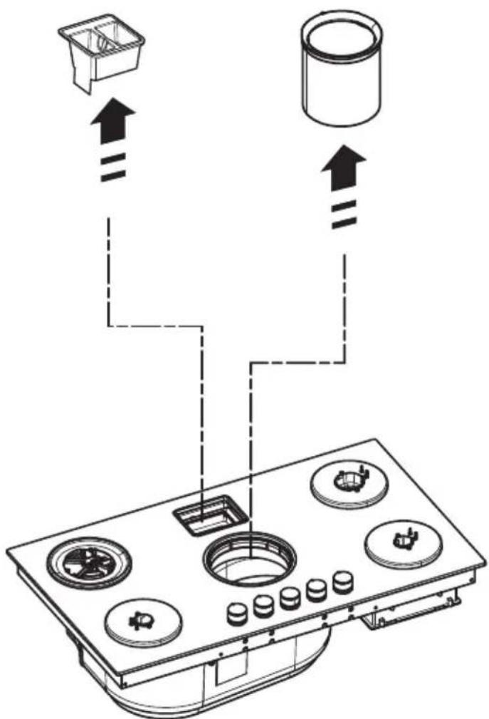
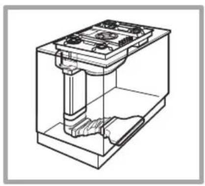
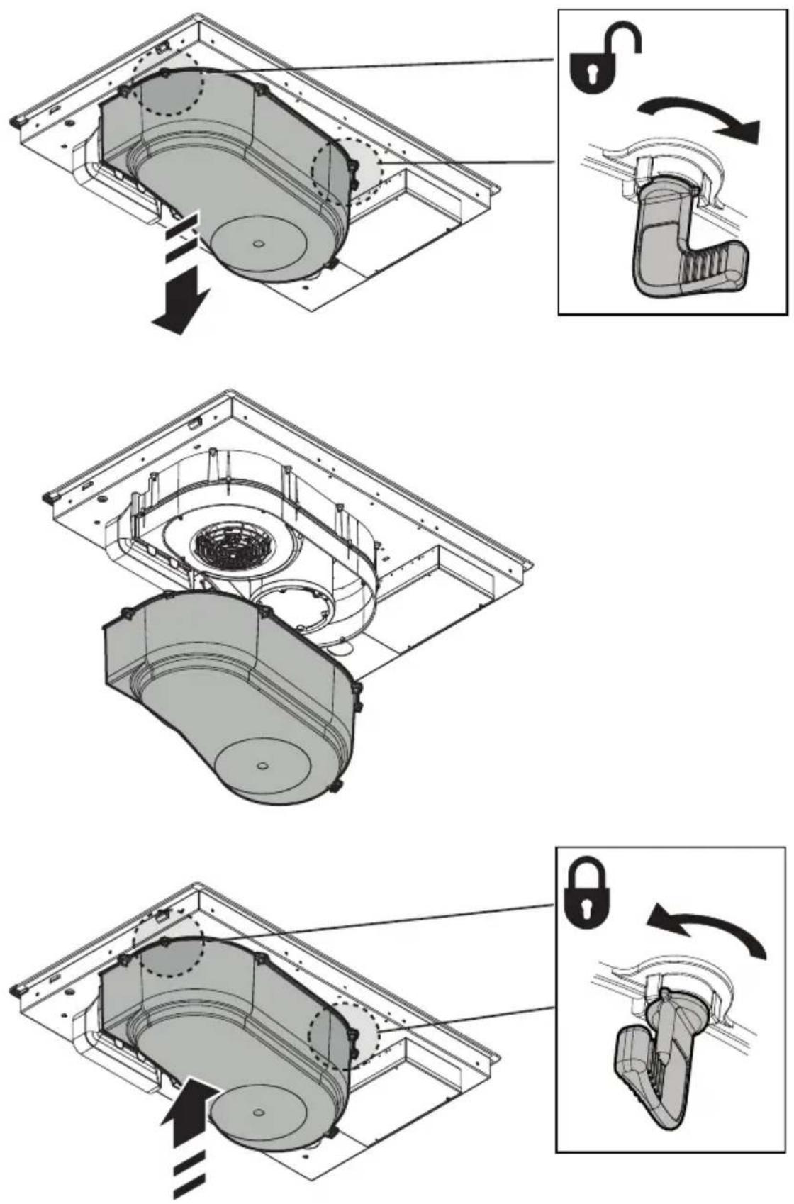
The extraction system can be used in two versions: external extraction and evacuation or as a filter with internal recirculation.

Extraction version
Fig.7
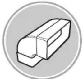
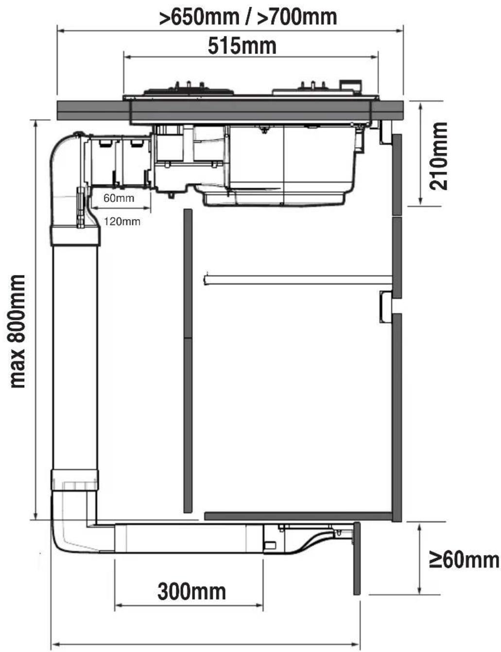
The fumes are evacuated towards the outside through a series of pipes (bought separately) fastened to the supplied connecting flange.
The diameter of the exhaust pipe must be equivalent to the diameter of the connecting ring:
- for rectangular outlets 222 x 89 mm
- for circular outlets ∅ 150 mm (*)
For more information, see the page relative to the extraction version in the illustrated part of this manual. Fig.7c
Connect the product to wall-mounted exhaust pipes and holes with a diameter equivalent to the air outlet (connecting flange). Using wall-mounted exhaust pipes and holes with a smaller diameter may reduce the efficiency of extraction and drastically increase noise levels.
All responsibility in this regard is therefore denied.
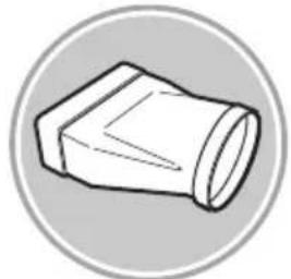
Keep duct as short as possible.
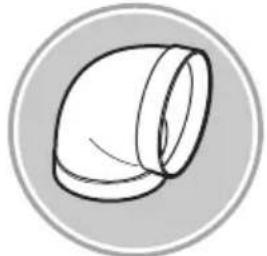
① Use ducting with the least possible number of curves (maximum angle: 90°).
Avoid drastic changes in the ducting diameter.

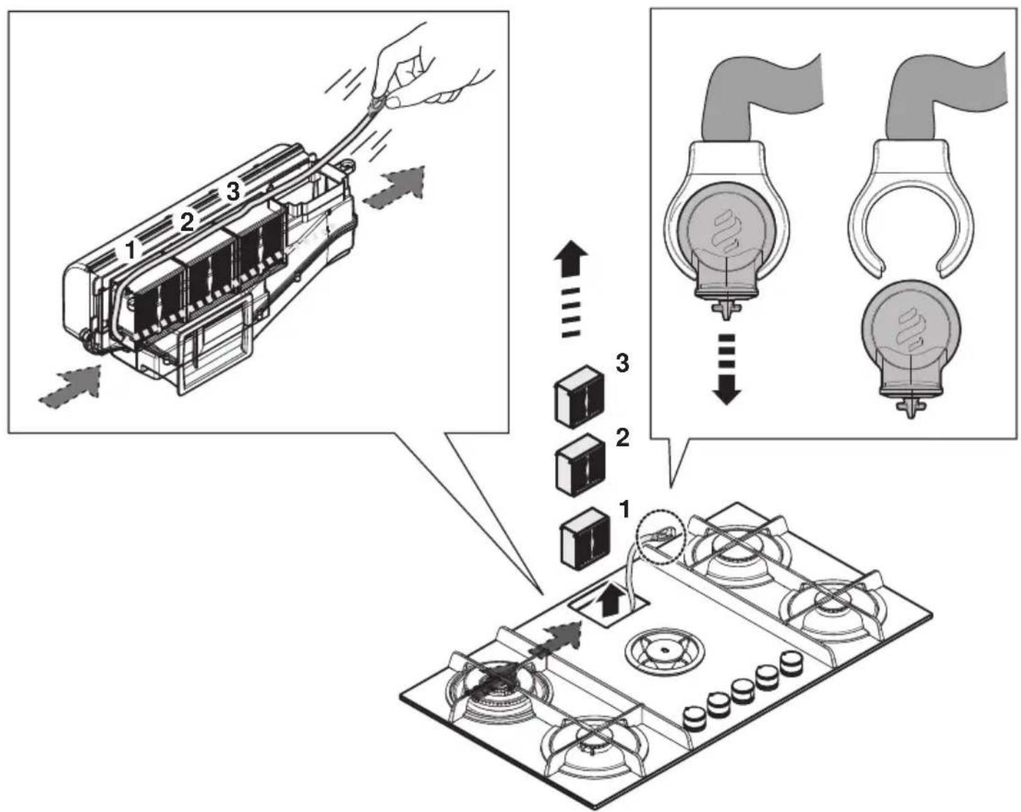
Filtration version
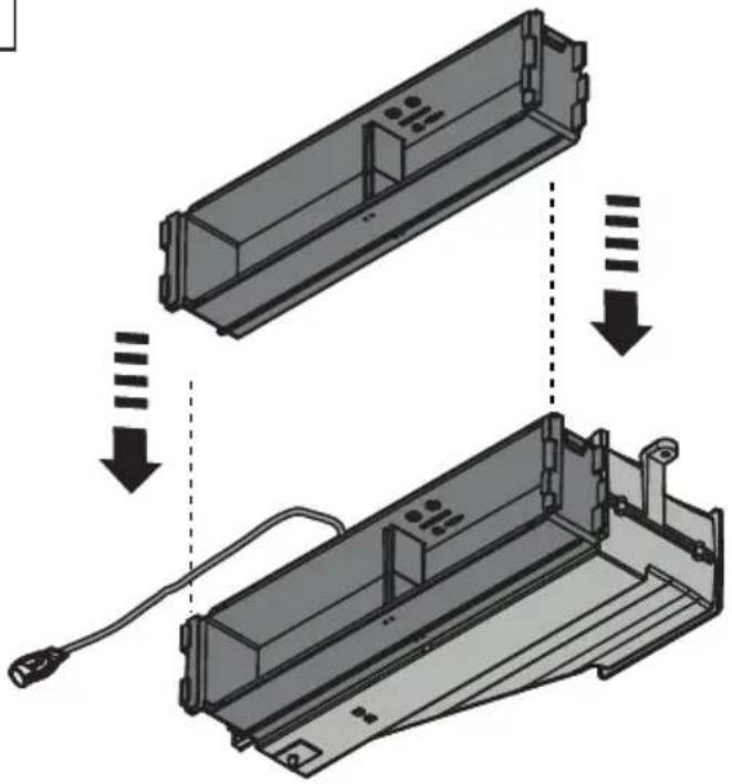
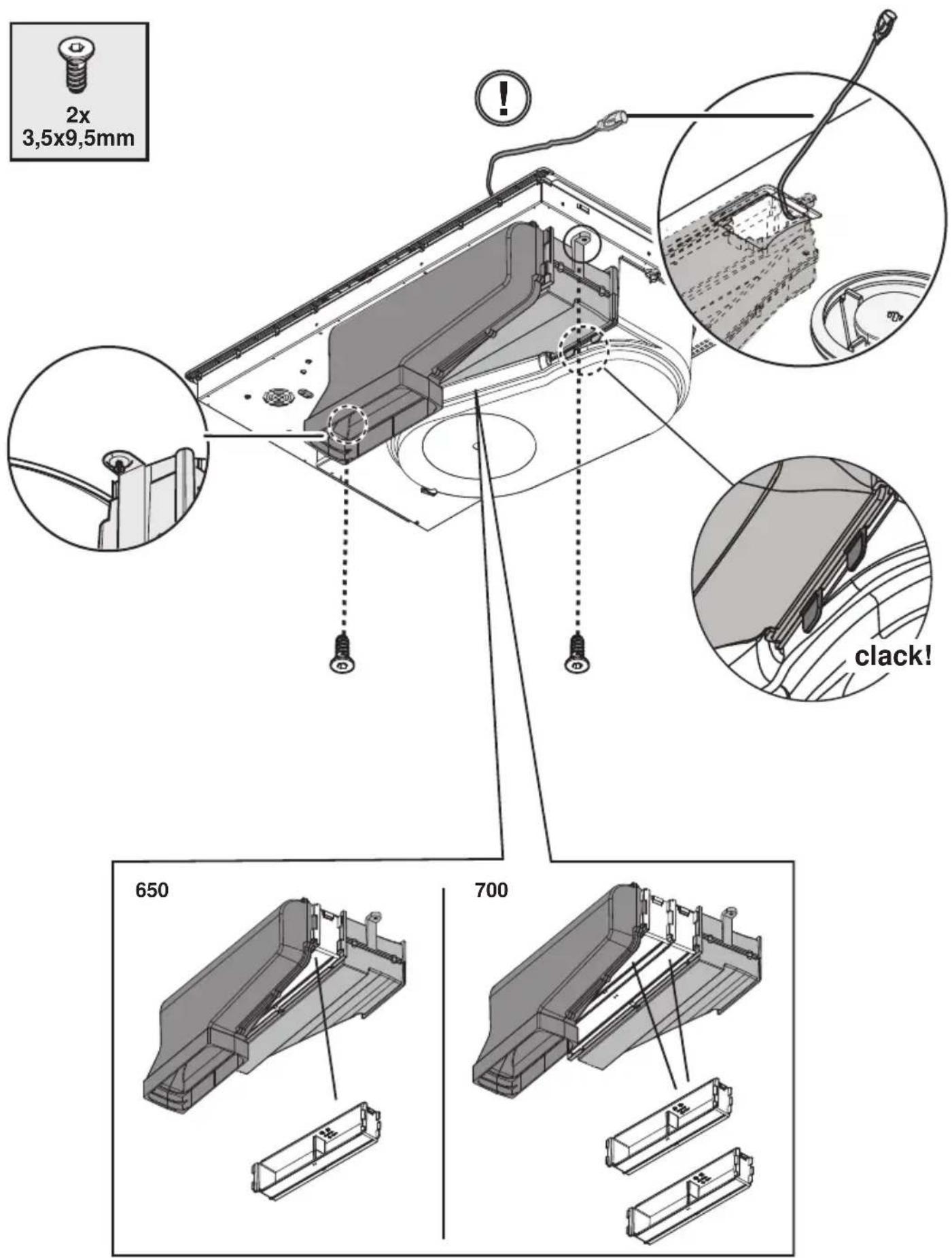
Fig. 8
The extracted air will be filtered in special grease filters and odour filters before being sent back into the room.
The product is supplied with all parts necessary for standard installation, with the air outlet positioned in the front part of the cabinet plinth.
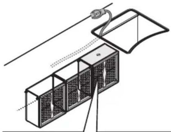
The product is equipped with four filter packs that trap odours thanks to the activated carbons.
The activated carbons are integrated into a non-woven fabric matrix, making them easily and completely accessible to impurities, thus creating a high absorption surface.
For more information, see the page relative to the filtration version (in the illustrated part of this manual).
Fig. 13b
Visit the websites www.elica.com and www.shop.elica.com to check the complete range of available kits for different types of filtration and extraction installations.
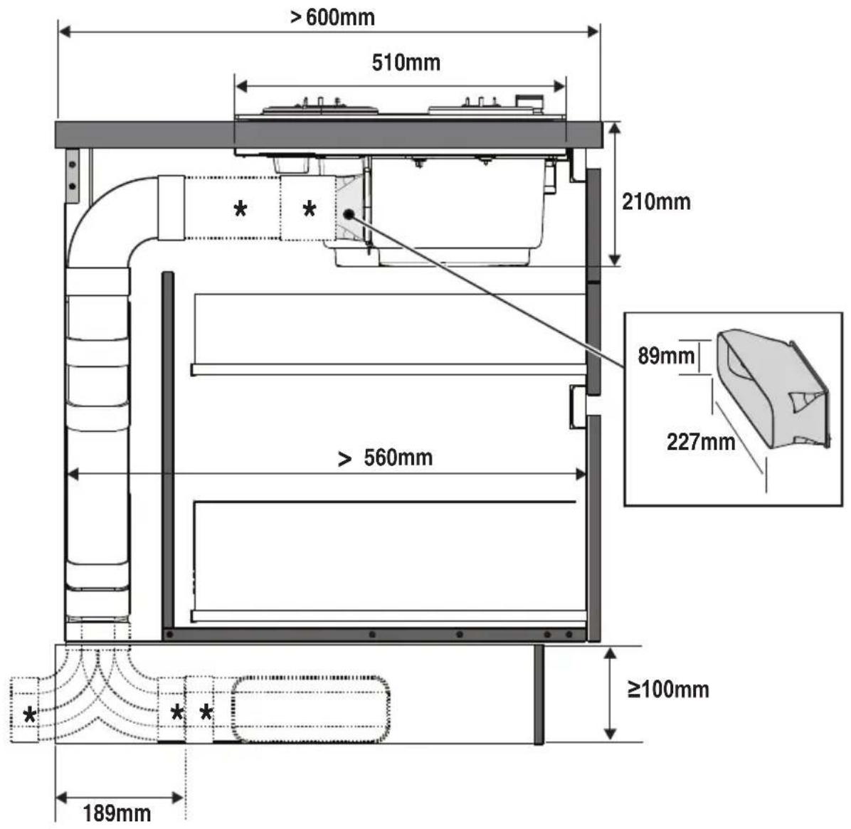
3. Installation
The electrical and mechanical installation and gas connection must be carried out by specialised personnel.
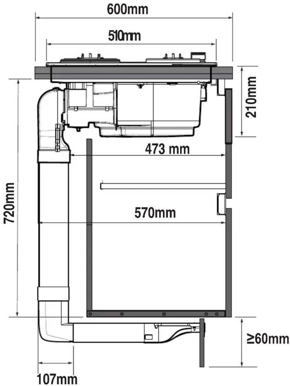
The electrical appliance is designed to be built-in to a 2-6 cm thick worktop in the case of TOP installations; 2.5-6 cm in the case of FLUSH installations.
The minimum distance between the hob and the wall must be at least 5 cm from the rear part, at least 40 cm from the side walls and at least 50 cm from the wall units above.
This product is a class 3 recessed appliance.
Fig. 1a /1b

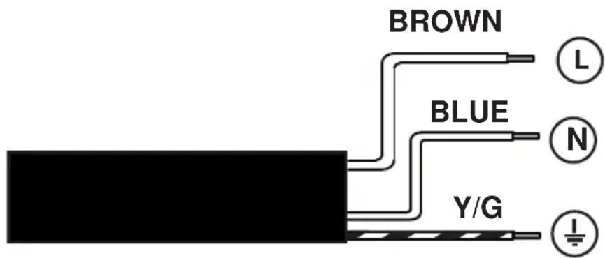
3.1 Electrical connection
Fig. 3
- The installation must be performed by professionally qualified personnel familiar with the applicable installation and safety standards • The manufacturer declines all responsibility to persons, animals or property if the guidelines provided in this handbook are not followed. • The power cable must be long enough to allow removal of the hob from the worktop • Make sure that the voltage on the rating plate on the bottom of the device corresponds to that of the house where it will be installed. • Do not use extension cords. • Earthing is required by law • The earth power cable must be 2cm longer than the other cables • At no point along the length of the cable must it reach a temperature of 50°C above the room temperature. • The device is intended to be permanently connected to the electrical network, therefore, make the connection to the fixed network via a standard omnipolar switch, which assures the complete disconnection of the mains under category III over-voltage conditions, and which is readily
accessible after the installation.
- Please note! Before reconnecting the circuit to the mains power supply, make sure that it is working correctly, always check that the power cable is correctly installed. - Please note! The interconnection cable must be replaced by the authorised technical support service or by a person with similar qualifications.
3.2 Gas connection
- The installation must be performed by professionally qualified personnel familiar with the applicable installation and safety regulations. Connect the device to the cylinder or gas supply in accordance with the provisions of the standards in force, making sure in advance that the equipment is pre-configured for the type of gas available.

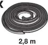
- If not, refer to: “Adaptation to different types of gas”. - Check also that the supply pressure falls within the values in the table: “Characteristics of gas burners”. - Rigid/semi-rigid metal connection - Make the connection with metal fittings and pipes (also flexible) to avoid straining the internal parts of the appliance. - When installing flexible pipes, make sure that, when fully extended, their length does not exceed 2 metres. - Only use pipes that comply with the national standards in force. - N.B. - Once the installation is complete, check that the entire connection system is properly sealed with a soapy solution.
Never use a flame to perform this check.
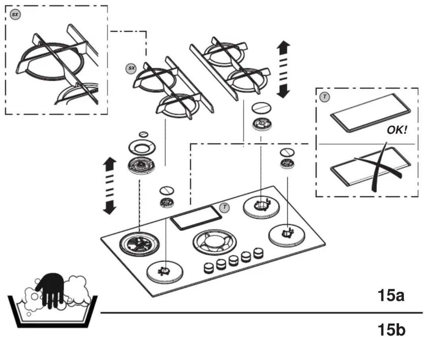
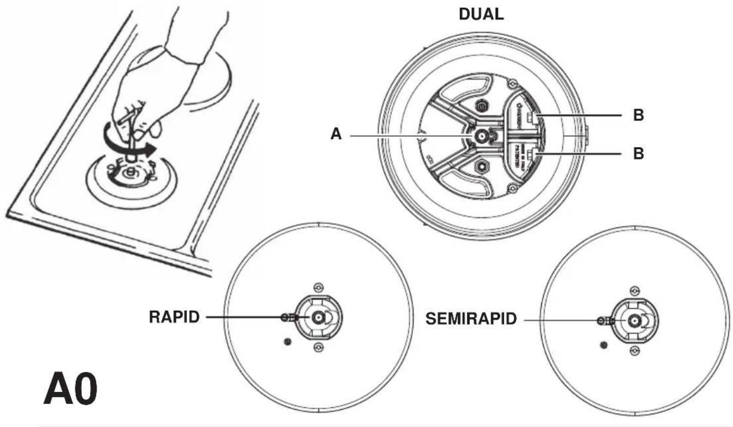
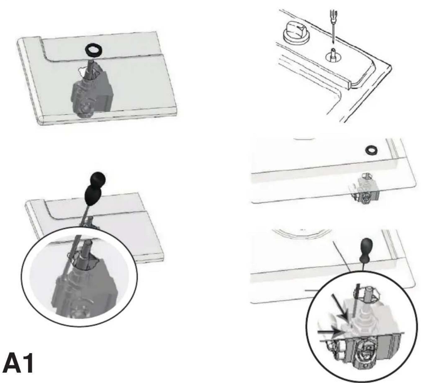
- Adaptation to different types of gas To adapt the appliance to a type of gas other than that for which it is designed (as indicated on the label fixed to the lower part of the hob or the packaging), the burner nozzles must be replaced by performing the following operations: ● 1 - remove the stove top grids and remove the burners from their slots ● 2 - unscrew the nozzles, using a 7mm socket wrench and replace them with ones suitable for the new type of gas (see table “Characteristics of gas burners”) ● 3 - reassemble the parts following the steps in reverse order ● Warning! At the end of the operation, replace the old calibration label with the one for the new gas used. FIG.A0.
- Minimum adjustment ● For minimum adjustment: ● 1 - turn the tap to the minimum setting ● 2- remove the knob and adjust the screw located inside or next to the valve shaft, with a suitable screwdriver, until a small regular flame is obtained FIG.A01 ● 3 - check that by turning the knob quickly, from maximum to minimum, the burners do not turn off ● 4 - if the safety device fails (thermocouple), with the burners on minimum setting, increase the minimum flow rate by adjusting the relevant screw. ● 5 - once the adjustment has been made, re-seal the seals on the by-pass with sealing wax or equivalent materials ● In the case of liquid gases (e.g. LPG), the adjustment screw must be screwed in completely. ● Warning! At the end of the operation, replace the old calibration label with the one for the new gas used. ●
Warning! If the pressure of the gas used is different (or variable) from that the one indicated, an appropriate pressure regulator on the inlet pipe must be installed that complies with the national standards in force. ● The amount of air required for combustion must not be less than 2.0 m3/h for each kW of installed power. See the table for the burner power.
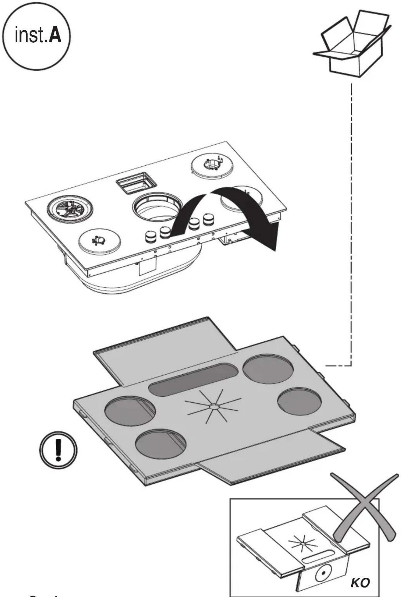
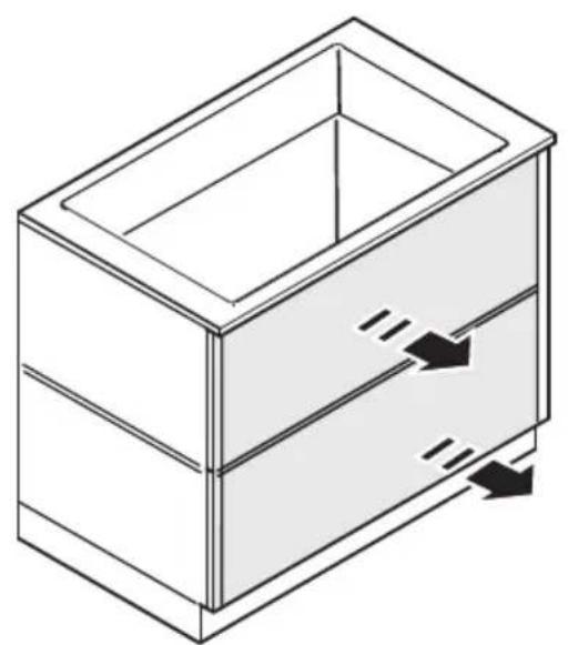
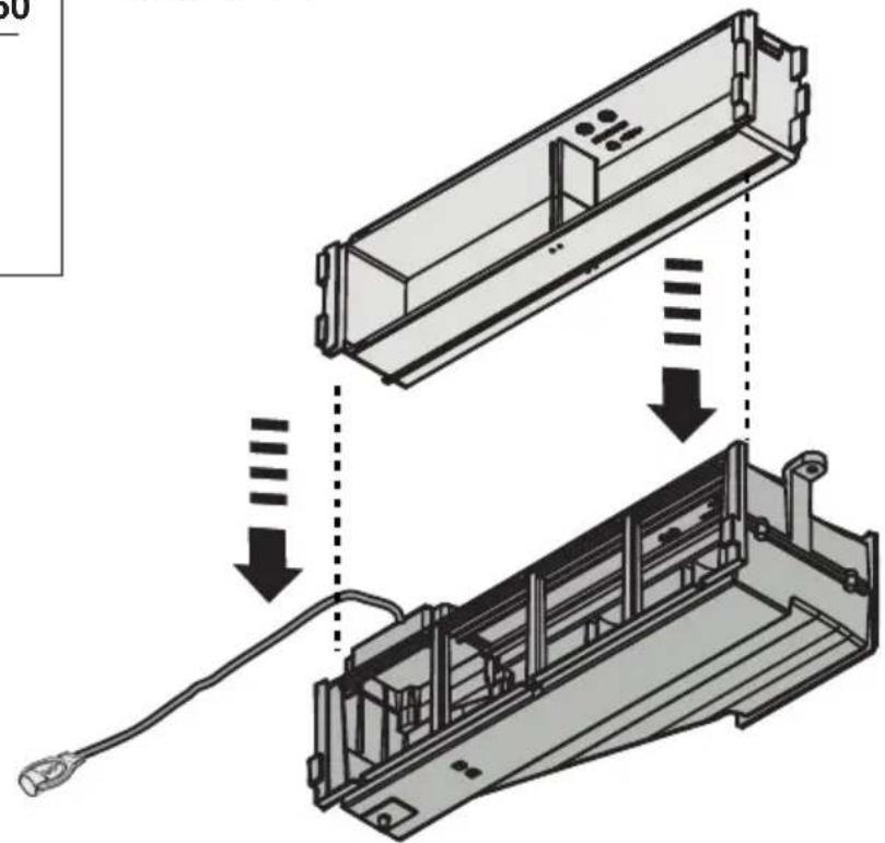
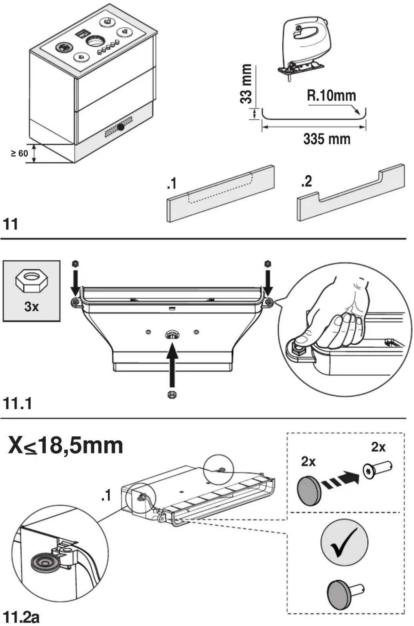
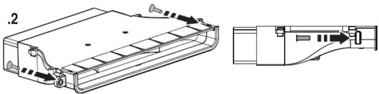
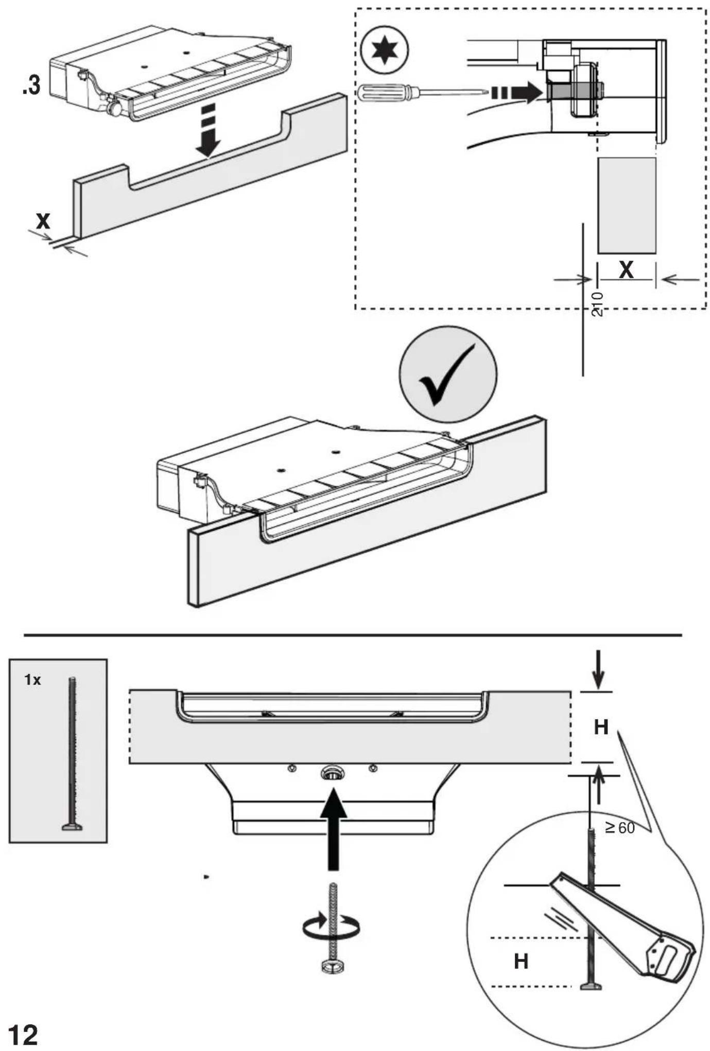
3.3 Mounting
Before starting the installation:
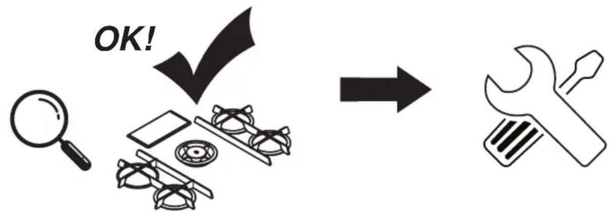
- After unpacking the product, check that it has not been damaged during transport and in the event of problem, please contact the reseller or the Customer support service before installing it.
- Check that the product is the right size for the installation area.
- Check for accessories (e.g. bags containing screws, warranty certificates, etc.) inside the packaging (placed there for transport reasons). Remove and keep them safe, if present.
- Also check that there is a power socket near the installation area.
Preparing the cabinet for installation:
- The product cannot be installed above cooling appliances, dishwashers, heaters, ovens, washing machines and dryers.
- Create the cut-outs in the cabinet before inserting the hob and carefully remove any shavings or sawdust.
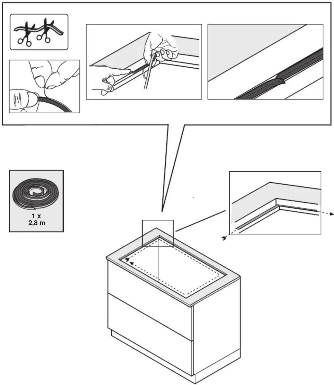
IMPORTANT: use a single-component adhesive sealant (S), which withstands temperatures up to 250°; before installation, thoroughly clean the surfaces to stick and eliminate any substance that may compromise adhesion, (e.g. release agents, preservatives, fats, oil, dust, traces of old adhesives, etc.); the adhesive should be uniformly spread all around the outside of the frame; after sticking, leave the adhesive to dry for about 24 hours.
Fig. 1b
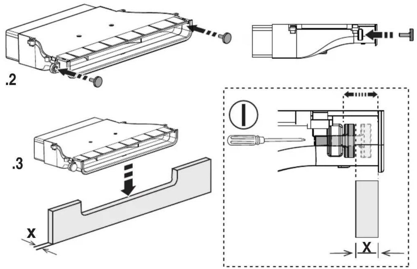
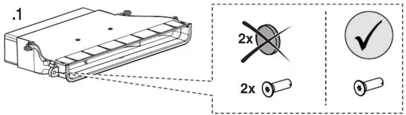
Caution! Failure to install screws and fasteners in accordance with these instructions may result in electrical hazards.
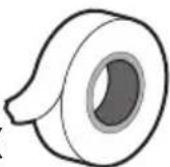
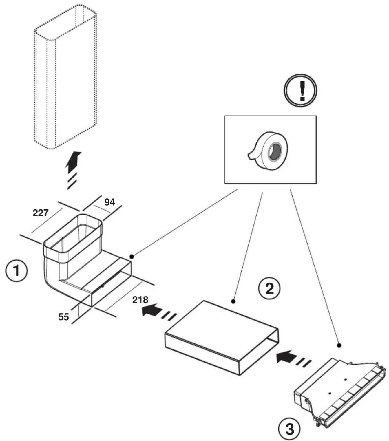
Note: to ensure the correct installation of the product, it is recommended to tape the pipes using an adhesive with the following characteristics:
- soft elastic PVC film, with an acrylic-based adhesive
- which complies with DIN EN 60454 regulations
- self-extinguishing
- excellent resistance against wear
- resistant against temperature fluctuations
- can be used in low temperatures
4. Operation
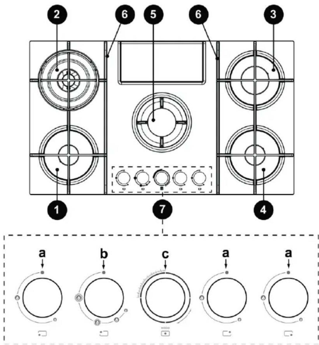
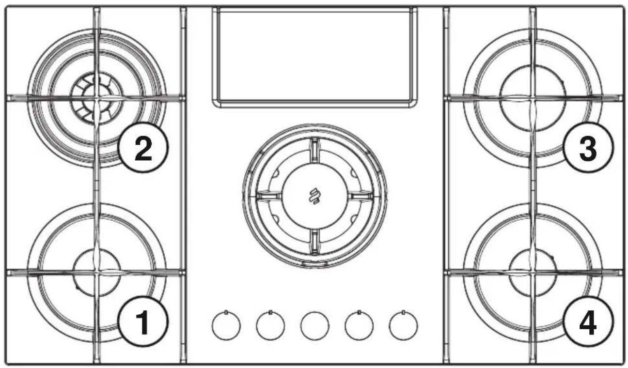
1- Semi-rapid burner
2- Dual burner
3- Rapid burner
4- Semi-rapid burner
5- Extraction area / Removable support
6- Removable grids
7- Control knobs:
a. Gas burner on/off
b. Dual gas burner on/off
c. Extraction fan on/off
3.2 Using the hob USING THE HOB
The burners are ignited (1-3-4) by pressing the corresponding knob and turning it counter-clockwise until the indicator is in
the maximum position
The electric discharge between the igniter and the burner lights the burner in question. When lit, immediately release the knob and adjust the flame as required.
The burner is ignited by keeping the knob fully pressed in the maximum position for about 3/5 seconds. When releasing the knob, make sure that the burner stays on.
NB = in the event of a power failure, the burner can be lit by turning the knob in the same way and placing a small flame close to the holes in the upper part of the burner.
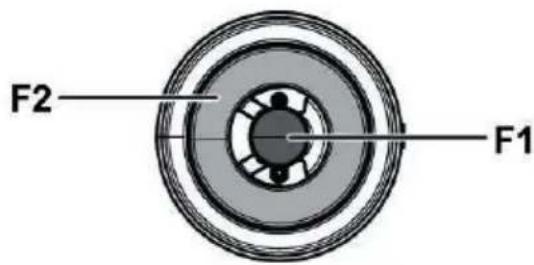
The Dual burner is ignited (2) in the same way, by pressing and turning the knob counter-clockwise.
In this case, each position corresponds to a different burner operation, as indicated below:
1st click: F1 high flame - F2 high flame.
2nd click: F1 high flame - F2 low flame.
3rd click: F1 high flame - F2 off.
4th click: F1 low flame - F2 off.
USING THE EXTRACTOR FAN
NB = the extraction fan knob has back-lit dial; depending on the function to be performed, the knob can be turned or pressed.
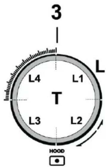
•To select the extraction speeds available:
Turn the knob (3) clockwise to switch on and increase the extraction speed and anti-clockwise to decrease it, and turn off the hood.
The crown (L) lights up to indicate the chosen extraction speed:
•L1 on
speed 1
•L1+L2 on
speed 2
•L1+L2+L3 on
speed 3
•L1+L2+L3+L4-flashing slowly
speed 4 (boost 1): Duration 30 minutes after which the hood is automatically set to speed 3
•L1+L2+L3+L4-flashing rapidly
speed 5 (boost 2): duration 7 minutes, after which the hood is automatically set to speed 3
•L off:
Extraction motor off
•Timer
The extraction fan has a timer function for automatic timed switch-off.
NB = there is no timer for Boost 1 and Boost 2 speeds, which are already timed
To activate the timer, press the knob (3-T) for 2 seconds;
- if you are using speed 1: the hood will automatically switch off after 15 minutes (L1 flashes)
- if you are using speed 2: the hood will automatically switch off after 10 minutes (L1 is fixed – L2 flashes)
- if you are using speed 3: the hood will automatically switch off after 5 minutes (L1+L2 are fixed - L3 flashes)
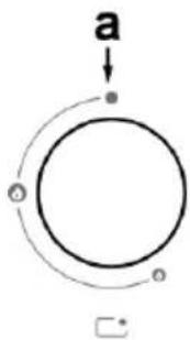
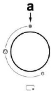
•Filter saturation check device
The hood is fitted with a device that signals when the filters require maintenance
To activate the filter saturation check device, proceed as follows:
1 - Switch off the hood.
2 - Press the knob (3-T), for 5 seconds;
The crown (L) turns on fully and flashes, indicating that you have entered the filter settings menus
NB = the anti-grease filter saturation check device is usually already enabled;
The active carbon filter check device is usually disabled
3a -Anti-grease filter
Turn the knob (3) clockwise, L2+L3 are on and fixed
Press the knob: L2 +L3 start flashing, the anti-grease filter check device is disabled
Press the knob: L2 +L3 stop flashing and become fixed, the anti-grease filter check device is enabled
3b -Active carbon filters
Turn the knob (3) anti-clockwise L1+L4 are on and flashing. Press the knob: L1 + L4 stop flashing and become fixed, the active carbon filter check device is enabled
Press the knob: L1 +L4 start flashing, the active carbon filter check device is disabled
4 - Press the knob (3-T) again for 5 seconds; the crown (L) flashes, then turns off, indicating that you have exited the filter settings menu
NB = you automatically exit the menu after 1 minute in any case
Anti-grease filter saturation warning
L2 + L3 flash when maintenance of the anti-grease filter is required
Active carbon filter saturation warning
L1 + L4 flash when maintenance of the active carbon filter is required
Filter saturation warning reset
After filter maintenance, press the knob (3-T) for 4 seconds: the LED lights L switch off, confirming that they have been reset.
Note: if the saturation warnings occur at the same time (anti-grease and active carbon filter saturation), the reset operation must be repeated twice.
Power tables
| POWER SUPPLY | BURNERS | INJECTOR MARKING | FLOW RATE Kw | CONSUMPTION | GAS PRESSURE | |||
| TYPE | NORM. PRESSURE mbar | min. | nom. | max. | ||||
| Gas | G20 20mbar | DUAL EXTERNAL - B | 89 | 2.7 | 334 l/h | 17 | 20 | 25 |
| DUAL CENT - A | 68 | 0.8 | ||||||
| RAPID SEMI-RAPID | 125 97 | 3 1.75 | 286 l/h 167 l/h | |||||
| Gas | G30 29mbar | DUAL EXTERNAL - B | 63 | 2.7 | 255 g/h | 20 | 28 - 30 | 35 |
| DUAL CENT - A | 46 | 0.8 | ||||||
| RAPID SEMI-RAPID | 80 66 | 2.5 1.75 | 182 g/h 127 g/h | |||||
| Gas | G25.3 25mbar | DUAL EXTERNAL - B | 92 | 2.7 | 382 l/h | 20 | 25 | 30 |
| DUAL CENT - A | 71 | 0.8 | ||||||
| RAPID SEMI-RAPID | 130 100 | 3 1.75 | 327l/h 191 l/h | |||||
| Gas | G30 50mbar | DUAL EXTERNAL - B | 54 | 2.7 | 255 g/h | 42.5 | 50 | 57.5 |
| DUAL CENT - A | 40 | 0.8 | ||||||
| RAPID SEMI-RAPID | 78 60 | 3 1.75 | 218 g/h 127 g/h | |||||
DUAL EXTERNAL - B
DUAL CENT - A
Fig. 19
Note: the valid configurations are those relative to the fitted nozzles supplied with the kit (which vary depending on the product).
5. Maintenance
Hob maintenance
Warning! Before carrying out any cleaning or maintenance operations, make sure that the cooking areas are switched off and cold.
5.1 Cleaning
The hob must be cleaned after each use.
Important:
Do not use abrasive sponges, scouring pads. Their use, over time, may ruin the glass.
Do not use chemical irritants, such as oven sprays or stain removers.
After each use, leave the hob to cool and clean it to remove deposits and stains caused by food residue.
Sugar or food with a high sugar content damages the hob and must be immediately removed.
Salt, sugar and sand may scratch the glass surface.
Use a soft cloth, paper towel or specific products to clean the hob (follow the Manufacturer's instructions).
DO NOT USE STEAM JET CLEANERS!!!
To ensure longer equipment life, it is essential to periodically perform a thorough general cleaning, keeping in mind the following:
- the glass, steel and/or enamelled parts must be cleaned with suitable (commercially available) non-abrasive or corrosive products. Avoid chlorine-based products (bleach, etc.)
- avoid leaving acid or alkaline substances (vinegar, salt, lemon juice, etc.) on the work surface;
the flame spreader and the caps (mobile parts of the burner) should be frequently washed with hot water and detergent, taking care to remove any dried-on dirt, dry thoroughly, and check that none of the holes in the flame spreader are even partly clogged.
After cleaning, reposition the grids and the burners correctly.
natural_image
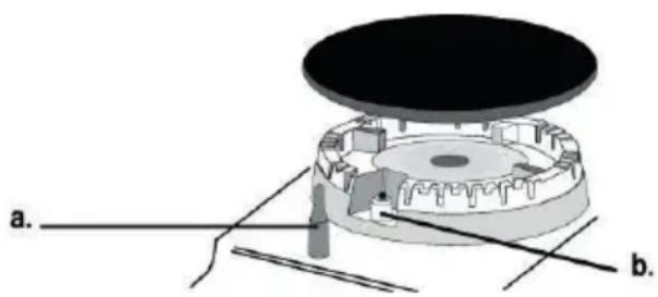
Technical diagram of a mechanical component with labeled parts (a and b), showing internal structure without any readable text or symbols.a. SAFETY DEVICES
b. Igniter for GAS BURNERS
NB: Any lubrication of the valves must be performed by qualified personnel who should be contacted in the event of faults. Periodically check the condition of the gas supply hose. In the event of leaks, request the immediate intervention of qualified personnel for replacement. Important:
If liquids accidentally or excessively leak out of the pots, the drain valve located on the lower part of the product can be opened so as to remove any residue and be able to clean in conditions of maximum hygiene.
Fig. 16
For a more complete and in-depth clean, the lower tray can be completely removed.
Fig. 18
Cleaning the metal grille:
The grille must be washed by hand with hot water and neutral detergent, then dried thoroughly to prevent oxidation.
Extractor fan maintenance
Cleaning
For cleaning, use ONLY a cloth moistened with neutral liquid detergents. DO NOT USE CLEANING UTENSILS OR TOOLS!
Avoid the use of products containing abrasives.
DO NOT USE ALCOHOL!
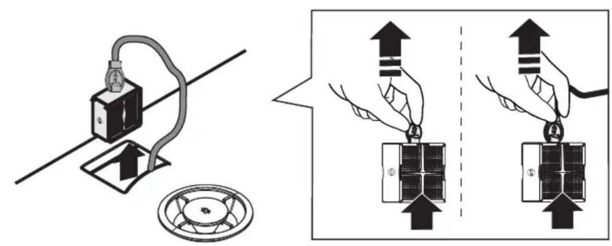
Grease filter
Traps grease particles generated by cooking.
Must be cleaned once per month (or when the filter saturation indication system indicates this need), with non-aggressive detergents, either manually or in the dishwasher at a low temperature and in a short cycle.
When cleaned in the dishwasher, the metal grease filter may discolour, but its filtering characteristics remain unchanged.
Fig. 15b
Activated carbon pleated filter
(Only for Filtration Version)
The filters trap odours thanks to the activated carbons. The activated carbons are integrated into a non-woven fabric matrix, making them easily and completely accessible to impurities, thus creating a high absorption surface. The activated carbon filters are saturated after more or less prolonged use, depending on the type of kitchen and the regularity with which the grease filter is cleaned. These odour filters cannot be regenerated and must be replaced when the warning lamp turns on.
Fig. 17-17a-17b-17c
5.2 Troubleshooting
The top may sometimes not work or not work correctly. Try troubleshooting before calling customer support. Firstly, check that there are no interruptions in the gas and electricity supply networks, and in particular that the gas taps upstream of the hob are open.
The burner does not ignite or the flame is not even
Check if:
•The gas outlet holes in the burner are blocked.
- All the mobile parts that make up the burner are correctly assembled.
•There are drafts near the stove top.
The flame does not stay lit
Check if:
- You have pressed the knob fully.
- You have kept the knob pressed down for long enough to activate the safety device.
•The gas outlet holes in the safety device are blocked.
The burner does not stay lit at the minimum setting
Check if:
•The gas outlet holes are blocked.
•There are drafts near the stove top.
•The minimum adjustment setting is correct.
The pans are unstable
Check if:
•The bottom of the pan is perfectly flat.
•The pan is centred on the burner or hot plate.
•The grids have been inverted.
If, despite all the checks, the stove top does not work and the problem you detected persists, call the technical support centre.
Communicate:
•the machine model (Mod.)
•the serial number (S/N)
The serial number can be found on the information data label located on the device and/or on the packaging.
! Never use unauthorized technicians and always refuse the installation of non-original spare parts.
natural_image
Illustration of a cooking pot on a gas stove with cooking utensils (no text or symbols)natural_image
Technical diagram of a mechanical assembly with labeled parts (a and b), showing internal components and no readable text or symbols.natural_image
Illustration of a cooking pot on a gas stove with steam rising (no text or symbols)natural_image
Technical diagram of a mechanical component with labeled parts (a and b), showing internal components and no readable text or symbols.a. DISPOSITIF DE SÉCURITÉ
natural_image
Illustration of a cooking pot on a gas stove with steam rising (no text or symbols)natural_image
Technical diagram of a mechanical assembly with labeled parts (a and b), showing internal components and alignment lines (no text or symbols beyond labels)a. VEILIGHEIDSVOORZIENING
b. Ontstekingsbougie van de GASBRANDERS
natural_image
Illustration of a cooking pot on a gas stove with steam rising (no text or symbols)natural_image
Technical diagram of a mechanical assembly with labeled parts (a and b), showing internal components and no readable text or symbols.natural_image
Illustration of a cooking pot on a gas stove with steam rising (no text or symbols)natural_image
Technical diagram of a mechanical assembly with labeled components (a and b), showing internal components and alignment lines (no text or symbols beyond labels)natural_image
Illustration of a cooking pot on a gas stove with steam rising (no text or symbols)natural_image
3D mechanical assembly diagram showing a central component with flanged top and base, labeled with axes a. and b. (no text or symbols on the diagram itself)natural_image
Illustration of a cooking pan on a gas stove with steam rising (no text or symbols)natural_image
3D mechanical assembly diagram showing a circular component with labeled parts (a and b), no readable text or symbols present.a. SÄKERHETSANORDNING
natural_image
Illustration of a cooking pot on a gas stove with steam rising (no text or symbols)Imurin käyttö
natural_image
Technical diagram of a mechanical assembly with labeled parts (a and b), showing internal components and no readable text or symbols.a. TURVALAITE
b. Sytytystulppa: KAASUPOLTTIMET
natural_image
Illustration of a cooking stove with a pot and stove burner (no text or symbols)Bruke avtrekket
natural_image
3D mechanical assembly diagram showing a circular component with labeled parts (a and b), no readable text or symbols present.a. SIKKERHETSINNRETNINGER
b. Tennplugger for GASSBRENNERE
natural_image
Illustration of a cooking pot on a gas stove with steam rising (no text or symbols)Brug af sugeapparat
natural_image
3D mechanical assembly diagram showing a circular component with labeled parts (a and b), no readable text or symbols present.a. SIKKERHEDSANORDNING
natural_image
Illustration of a cooking pot on a gas stove with steamers and cooking utensils (no text or symbols)Użytkowanie okapu
natural_image
3D mechanical assembly diagram showing a circular component with labeled parts (a and b), no readable text or symbols present.a. URZĄDZENIE BEZPIECZEŃSTWA
natural_image
Illustration of a cooking pot on a gas stove with steam rising (no text or symbols)Použití odsávače
natural_image
Technical diagram of a mechanical assembly with labeled parts (a and b), showing internal components without any readable text or symbols.a. BEZPEČNOSTNÍ ZAŘÍZENÍ
b. Zapalovací svíčka PLYNOVÝCH HOŘÁKŮ
natural_image
Illustration of a cooking pot on a gas stove with steam rising (no text or symbols)Použitie odsávača
natural_image
Technical diagram of a mechanical component with labeled parts (a and b), showing internal structure without any readable text or symbols.a. BEZPEČNOSTNÉ ZARIADENIE
b. Zapal'ovacia sviečka PLYNOVÝCH HORÁKOV
- model stroja (Mod.)
natural_image
Illustration of a cooking pot on a gas stove with cooking utensils (no text or symbols)Употреба на аспиратора
natural_image
Technical diagram of a mechanical assembly with labeled parts (a and b), showing internal components and no readable text or symbols.natural_image
Illustration of a cooking pot on a gas stove with steamers and cooking utensils (no text or symbols)natural_image
Mechanical assembly diagram showing a circular component with internal gears and a top plate, labeled with 'a.' and 'b.' (no text or symbols on the diagram itself)a. DISPOZITIV DE SIGURANTĂ
natural_image
Illustration of a cooking setup with a pot, stove, and cooking utensils (no text or symbols)flowchart
graph TD
    b --> A
    A --> B
    B --> C
    C --> D
    D --> E
    E --> F
    F --> G
    G --> H
    H --> I
    I --> J
    J --> K
    K --> L
    L --> M
    M --> N
    N --> O
    O --> P
    P --> Q
    Q --> R
    R --> S
    S --> T
    T --> U
    U --> V
    V --> W
    W --> X
    X --> Y
    Y --> Z
    Z --> A
natural_image
3D mechanical assembly diagram showing a circular component with internal gears and a central hub, labeled with parts a and b (no text or symbols present)natural_image
Illustration of a cooking pot on a gas stove with a stirrer (no text or symbols)Anumad on ebastabiilsed
Veenduge järgmises.
natural_image
Illustration of a cooking pot on a gas stove with steam rising (no text or symbols)natural_image
Mechanical assembly diagram showing a circular component with internal gears and labeled parts (a and b), no readable text or symbols present.natural_image
Illustration of a cooking pot on a gas stove with steam rising (no text or symbols)natural_image
Technical diagram of a mechanical assembly with labeled components (a and b), showing internal components and no readable text or symbols.a. DROŠĪBAS IERĪCE
natural_image
Illustration of a cooking pot on a gas stove with steamers and cooking utensils (no text or symbols)Uporaba sesalnika
natural_image
Illustration of a cooking pot on a gas stove with steam rising (no text or symbols)Uporaba nape
Sustav za usisavanje se može koristiti u načinu rada za ekstrakciju i evakuaciju zraka ili za filtriranje za unutarnju recirkulaciju.

Usisna verzija
SI.7
Para se evakuira prema van kroz niz cijevi (moraju se kupiti odvojeno) pričvršćenih na isporučenu prirubnicu za spajanje.
natural_image
3D mechanical assembly diagram showing a circular component with labeled parts (a and b), no readable text or symbols present.a. SIGURNOSNI UREĐAJ
NEMOJTE KORISTITI ALKOHOL!
Filtar za mast
natural_image
Illustration of a cooking pot on a gas stove with steam rising (no text or symbols)natural_image
3D mechanical assembly diagram showing a circular component with labeled parts (a and b), no readable text or symbols present.a. EMNİYET DONANIMI
natural_image
Mechanical assembly diagram showing a circular component with internal components and labeled parts (a and b), no readable text or symbols present.a. جهاز السلام
natural_image
Illustration of a cooking pot on a stovetop with steam rising (no text or symbols)


- a. DISPOSITIVO DI SICUREZZA
- EN - Instruction on mounting and use
- Warnings
- Use
- Energy saving
- Using the extractor fan
- Extraction version
- Fig.7
- Filtration version
- Fig. 8
- Installation
- Electrical connection
- Fig. 3
- Gas connection
- Mounting
- Preparing the cabinet for installation:
- Fig. 1b
- Operation
- Using the hob USING THE HOB
- •To select the extraction speeds available:
- •Timer
- •Filter saturation check device
- 3a -Anti-grease filter
- 3b -Active carbon filters
- Anti-grease filter saturation warning
- Active carbon filter saturation warning
- Filter saturation warning reset
- Maintenance
- Hob maintenance
- Cleaning
- Important:
- DO NOT USE STEAM JET CLEANERS!!!
- Extractor fan maintenance
- Cleaning
- Grease filter
- Activated carbon pleated filter
- (Only for Filtration Version)
- Troubleshooting
- The burner does not ignite or the flame is not even
- The flame does not stay lit
- The burner does not stay lit at the minimum setting
- The pans are unstable
- a. DISPOSITIF DE SÉCURITÉ
- Imurin käyttö
- Bruke avtrekket
- a. SIKKERHETSINNRETNINGER
- Brug af sugeapparat
- Użytkowanie okapu
- a. URZĄDZENIE BEZPIECZEŃSTWA
- Použití odsávače
- Použitie odsávača
- a. BEZPEČNOSTNÉ ZARIADENIE
- Употреба на аспиратора
- a. DISPOZITIV DE SIGURANTĂ
- Anumad on ebastabiilsed
- Uporaba sesalnika
- Uporaba nape
- Usisna verzija
- SI.7
- Filtar za mast
- a. EMNİYET DONANIMI
Brand : ELICA
Model : NikolaTesla Flame BLA88
Category : Cooker