
Bluextreme 1100 - Aquarium Ferplast - Free user manual and instructions
Find the device manual for free Bluextreme 1100 Ferplast in PDF.
| Product type | External aquarium filter |
| Brand | Ferplast |
| Model | Bluextreme 1100 |
| Usage | Freshwater aquarium water filtration, indoor |
| Flow rate (L/h) | 1100 L/h |
| Max lift height | 1.5 m |
| Biological filter volume | 7 L |
| Total filtration volume | 11.4 L |
| Dimensions (L x D x H) | 22 x 22 x 40 cm |
| Weight | Approximately 4.5 kg (empty) |
| Power consumption | 16 W |
| Voltage | 220-240 V / 50 Hz |
| Recommended aquarium volume | 150 to 300 L |
| Number of filter baskets | 4 |
| Filtration type | Mechanical (foams), biological (cylinders), adsorbent (carbon, zeolite) |
| Priming system | Automatic (self-priming) |
| Materials | Non-toxic PVC for hoses, EPDM rubber for seals |
| Support feet | 4 plastic feet to glue |
| Included accessories | Flexible hoses (2x2m), BLUSTART capsules (x4), accessory kit (hoses, spray bar, nozzle, clips, suction cups) |
| Maintenance | Clean foams every 3-4 weeks; replace foams every 6 months; clean rotor every 3-4 months |
| Safety | 30 mA residual current device recommended; dry run protection; shut-off valves |
| Spare parts | Available (BLUMEC foams, BLUCARBON carbon, BLUZEOLITE zeolite, gaskets, etc.) |
| Warranty | Manufacturing defects; excludes foams, seals, improper use |
| Max water temperature | 35°C |
Frequently Asked Questions - Bluextreme 1100 Ferplast
User questions about Bluextreme 1100 Ferplast
0 question about this device. Answer the ones you know or ask your own.
Ask a new question about this device
Download the instructions for your Aquarium in PDF format for free! Find your manual Bluextreme 1100 - Ferplast and take your electronic device back in hand. On this page are published all the documents necessary for the use of your device. Bluextreme 1100 by Ferplast.
USER MANUAL Bluextreme 1100 Ferplast
Congratulations for having chosen a BLUEXTREME external filter by Ferplast, designed for your complete satisfaction and to ensure the total health of your fish and plants, without neglecting your safety, seeing as the powerful pump integrated in the filter is completely submergible and each component conforms to the relevant international safety regulations (CEI EN 60335-2-41).
Installation and management of the filter will be easy and fun. And, thanks to BLUEXTREME, only a few minutes of maintenance every month are enough to have an aquarium that is always in perfect efficient condition.
PRELIMINARY WARNINGS
• Make sure that the indicated voltage on the equipment label corresponds to the electric network.
• The filter is designed for interior use.
- Make sure that your home is protected upstream by a differential cutout switch with intervention current that does not exceed 30mA.
- Unplug the equipment from the power supply before performing any maintenance operations.
• The power cord must not be repaired or replaced: in case of damage, replace the entire equipment.
• The temperature of the liquid must not exceed 35^ C.
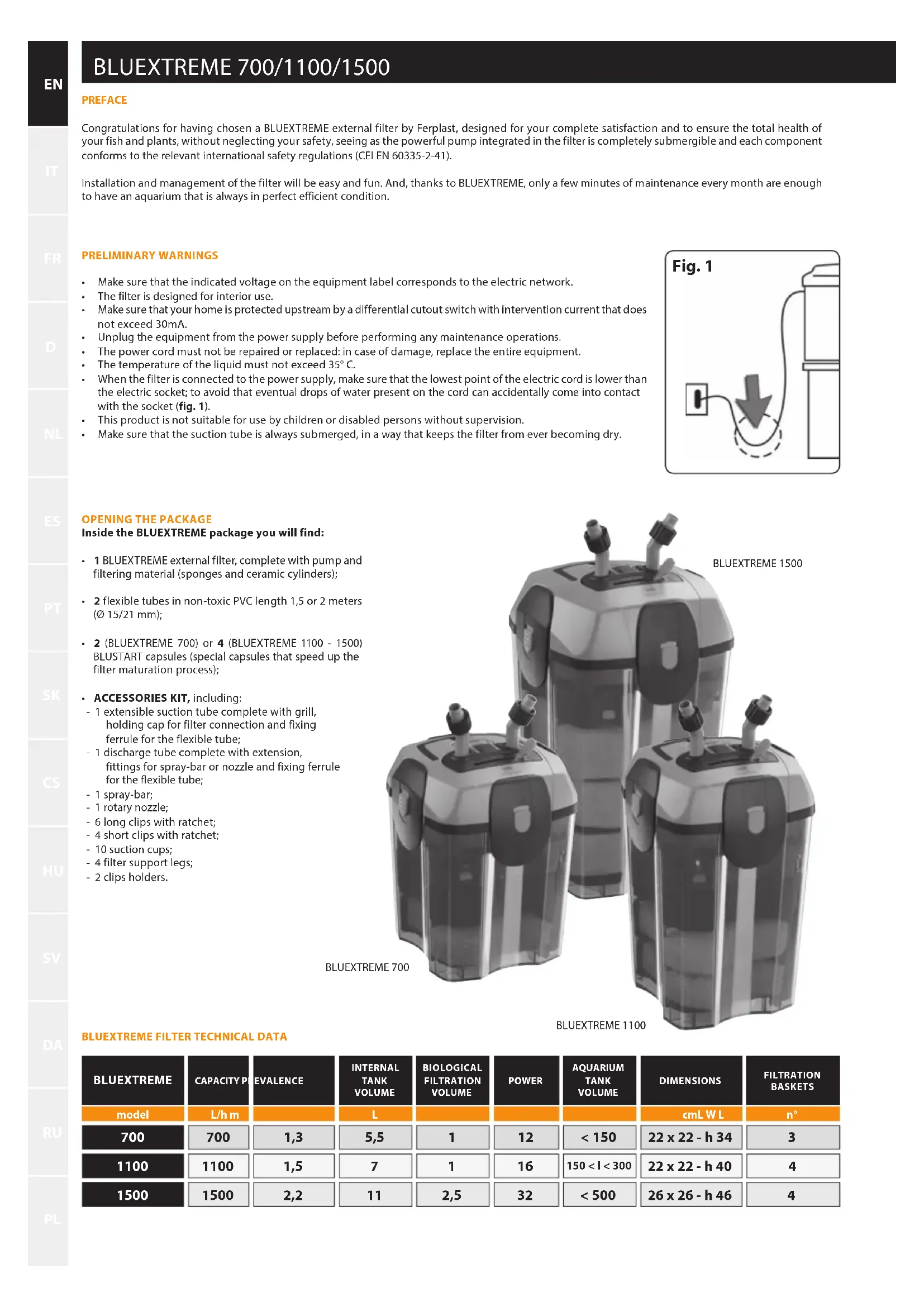
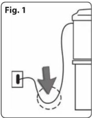
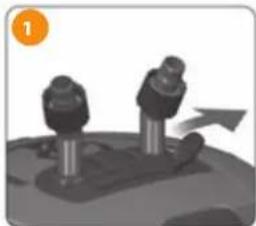
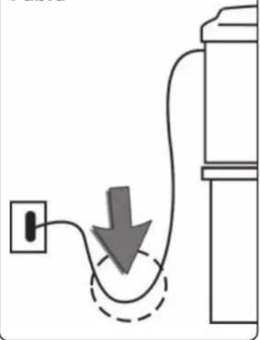
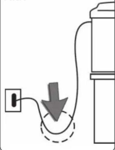
- When the filter is connected to the power supply, make sure that the lowest point of the electric cord is lower than the electric socket; to avoid that eventual drops of water present on the cord can accidentally come into contact with the socket (fig. 1).
• This product is not suitable for use by children or disabled persons without supervision.
• Make sure that the suction tube is always submerged, in a way that keeps the filter from ever becoming dry.
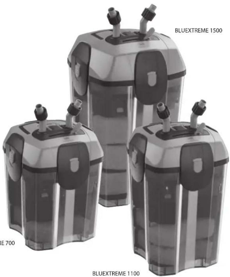
OPENING THE PACKAGE
Inside the BLUEXTREME package you will find:
• 1 BLUEXTREME external filter, complete with pump and filtering material (sponges and ceramic cylinders);
- 2 flexible tubes in non-toxic PVC length 1,5 or 2 meters (∅ 15/21 mm);
- 2 (BLUEXTREME 700) or 4 (BLUEXTREME 1100 - 1500) BLUSTART capsules (special capsules that speed up the filter maturation process);
- ACCESSORIES KIT, including:
- 1 extensible suction tube complete with grill, holding cap for filter connection and fixing ferrule for the flexible tube;
- 1 discharge tube complete with extension, fittings for spray-bar or nozzle and fixing ferrule for the flexible tube;
- 1 spray-bar;
- 1 rotary nozzle;
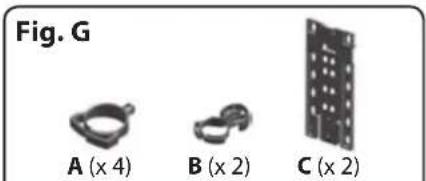
- 6 long clips with ratchet;
- 4 short clips with ratchet;
- 10 suction cups;
- 4 filter support legs;
- 2 clips holders.
BLUEXTREME FILTER TECHNICAL DATA
| BLUEXTREME | CAPACITY P | EVALENCE | INTERNAL TANK VOLUME | BIOLOGICAL FILTRATION VOLUME | POWER | AQUARIUM TANK VOLUME | DIMENSIONS | FILTRATION BASKETS |
| model | L/h m | L | cmL W L | n° | ||||
| 700 | 700 | 1,3 | 5,5 | 1 | 12 | < 150 | 22 x 22 - h 34 | 3 |
| 1100 | 1100 | 1,5 | 7 | 1 | 16 | 150 < l < 300 | 22 x 22 - h 40 | 4 |
| 1500 | 1500 | 2,2 | 11 | 2,5 | 32 | < 500 | 26 x 26 - h 46 | 4 |
BLUEXTREME:
discover all of its impressive qualities
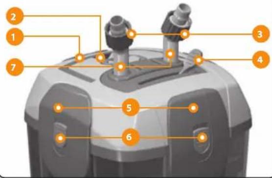
Filter handle
An easy to use handle for transporting the filter, designed to support it even when full of water (Fig. A/1).
Valve release lever
An easy to use lever that facilitates the extraction of the valves group from the filter cover during maintenance operations (Fig. A/2).
PLEASE NOTE: The Valves Group can be extracted from the cover only if the lever is in a vertical position.
Valve opening lever (safety system)
A lever that permits the opening/closing of the valves and the regulation of flow (Fig. A/4).
Tube fittings with ferrule
Easy to use 360° rotary fittings (Fig. A/7) with a ferrule that permits a secure fitting onto the flexible tube (Fig. A/3).
Valves group
An element easily extracted from the cover thanks to the release lever, which contains the valves for the interception of the water flow (Fig. A/10).
PLEASE NOTE: When extracted from the cover, a special system blocks the valve opening lever, so that it cannot move accidentally and cause bothersome water leakage.
Hooks
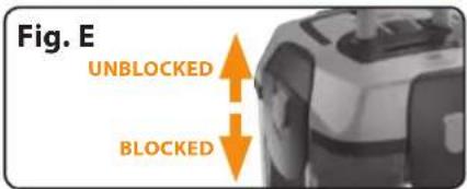
4 strong hooks for a tight hold between the cover and the filter tank (Fig. A/5). A special button permits blocking of the hook, when closed, in order to avoid bothersome accidental opening (Fig. A/6).
PLEASE NOTE: Red: blocked hook; Green: unblocked hook.
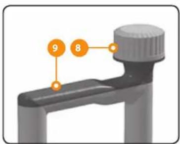
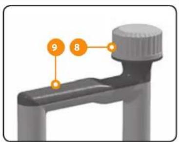
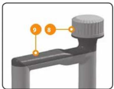
Tank seal
Special seal in EPDM rubber, to guarantee the maximum hold between the cover and tank (Fig. A/8).
Pre-chamber seal
Special seal in EPDM expanded with closed cells that guarantees water flow from the filter input to the bottom of the tank, without any preferential passage (Fig. A/9).
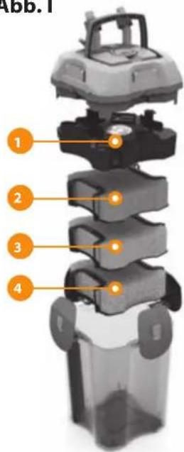
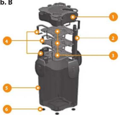
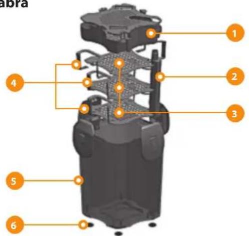
Ceramic cylinders basket
Easy to use basket containing ceramic cylinders for biological filtration.
This position optimizes filter efficiency (Fig. B/1).
Water passage tube
An integrated tube that ensures a direct flow of water from the aquarium to the bottom of the tank (Fig. B/2).
Filtration material basket
Easy to use baskets containing sponges of varied porosity, easily adaptable to other types of materials (Fig. B/3). The special adjustable handles ensure that their position is always well adhered to the tank wall, in a way that avoids the preferential passages of water around the sponges (Fig. B/4). The filtration materials can be replaced with others including perlon wool BLUFIBRE (mechanical filtration), activated charcoal in grains BLUCARBON and the zeolite BLUZEOLITE (absorbent filtration) or other materials, being careful not to clog the filter.
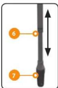
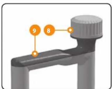
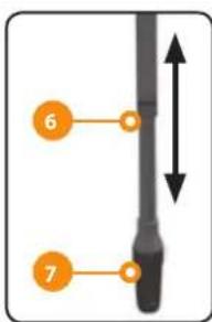
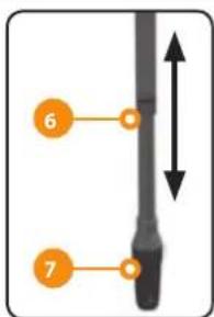
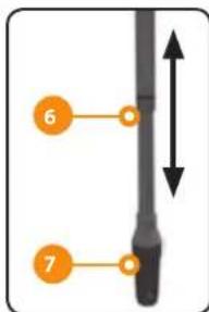
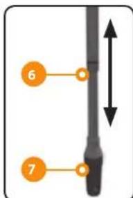
Suction tube
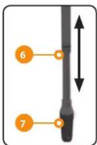
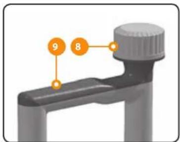
Special tube for suctioning the water in the aquarium, length adjustable (Fig. C/6). The tube includes a grill to avoid the entrance of leaves or fish into the filter (Fig. C/7) and a hole with a cap for the connection (Fig. C/8). In addition, the ferrule ensures a tight on the flexible tube.
Flexible tube
Special flexible tube in PVC with a diameter of 15/21 mm available pre-cut in 2 pieces.
Fig. A
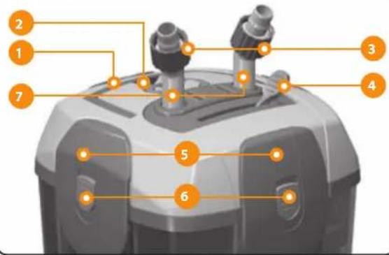
1 Filter handle
2 Valve release lever
3 Ferrules
4 Valve opening and flow regulation lever
5 Hook
6 Hook closure safety button
7 Tube fittings for water intake and discharge
8 Tank seal
9 Pre-chamber seal
10 Valves group
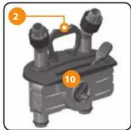
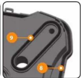
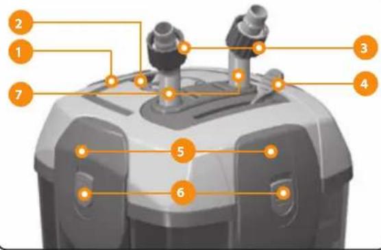
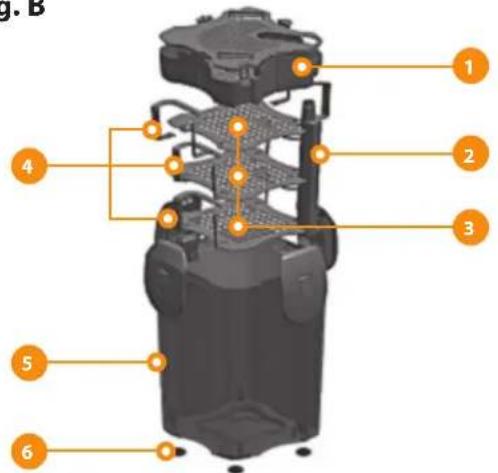
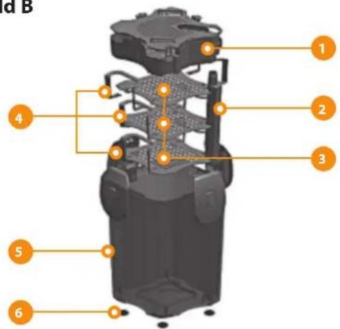
Fig. B

1 Ceramic cylinders basket with cover
2 Water passage tube towards tank bottom
3 Filtration materials basket with sponges
4 Adjustable basket handles
5 Tank
6 Support legs
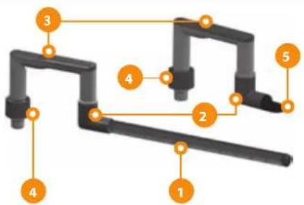
Fig. C
1 Spray-bar
2 "L" fittings
3 Fittings without cap
4 Ferrule for attachment to
the flexible tube
5 Rotary nozzle
6 Adjustable suction tube
7 Grill
8 Holding cap for filter
connection
9 Fittings with cap


Setting up the aquarium
- Decorate the aquarium as recommended by your trusted shop owner or as indicated in the instructions manual.
- In any case, if you are setting up an aquarium with tropical fresh water fish, we recommend a uniform shallow layer of fertilizer.
- Fill the tank with water (we recommend using 50% tap water and 50% demineralized water for aquariums, even though this percentage can vary depending on the characteristics of your tap water).
- Set the temperature of the heater based on the chosen species of fish and plants (for example, for tropical fresh water aquariums, the average temperature is approximately 25 - 26^ ).
Install the external filter as described below
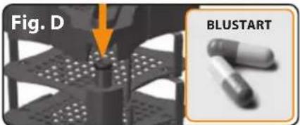
(Including the insertion of BLUSTART tablets)
- Place the plants in the aquarium after the water has been in the tank for 24 hours, to be sure the temperature and the chemical values of the water are stable.
- Before inserting the fish, you must wait 10-12 days, so the filter will be active. We recommend that you verify the parameters of the water of your aquarium with the measuring device MULTISTICK TESTER. Your trusted shop owner can also recommend the ideal values for temperature, hardness, etc., according to the species of fish and plants that you have chosen for your aquarium. It is a good idea to repeat the control frequently. When the fish are inserted, add the BLUSTART tablets included with the filter (1 in 700 and 2 in 1100 and 1500) in the bottom of the filter tank (you can introduce them easily through the tube, Fig. D).
- During the period of time necessary for filter maintenance, add a daily small dose of dry food: it will facilitate the formation of bacterial flora.
Preparation and installation of the filter
- Stick the four support legs of the filter to the bottom of the tank (Fig. B/6).
- Position the BLUEXTREME filter under the level of your aquarium (if you want, position it on the side of the aquarium, which can be done after start-up). All the Ferplast stands are designed to accommodate the filter and facilitate the passage of the tubes.
PLEASE NOTE: From the base of the filter support to the intake point of the tubes into the aquarium there must not be more than 160 cm. - Insert the valves group into the seat; lower the release lever and verify that the regulation lever is in the UNBLOCKED position.
- Extract the filter tank cover using the hooks (remember that the 4 safety buttons must first be raised, going from red to green, Fig. E) and verify the correct position of the filtration materials; release 1 (700) or 2 (1100-1500) BLUSTART capsules into the bottom of the filter tank (you can easily introduce them through the tube). Re-close the filter, positioning the cover over the tank, blocking it with the four hooks and closing the safety buttons.
PLEASE NOTE: do not lock one hook at a time, but pairs of hooks (one opposite the other).
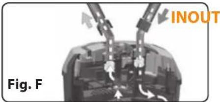
Be careful of the correct assembly and correct direction of the cover onto the tank, positioning it in a way to guarantee the continuity of the water's passage from the intake to the discharge (Fig. F). Make sure that there is not dirt or foreign matter on the seals under the cover.
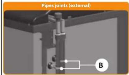
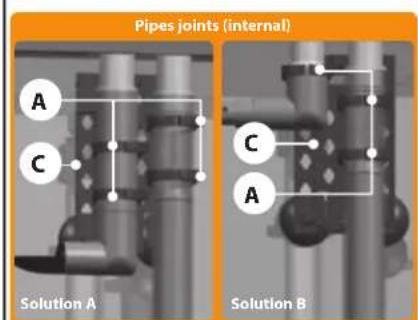
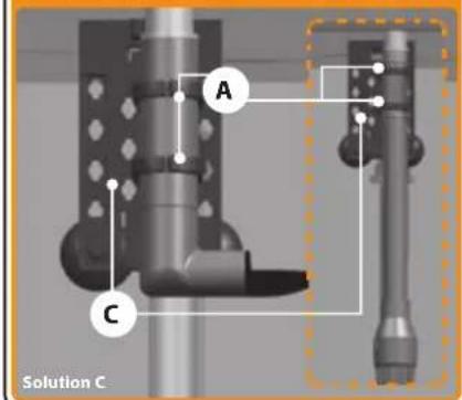
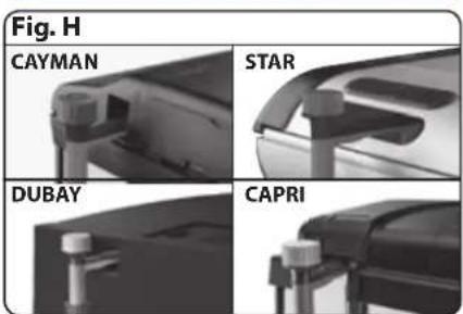
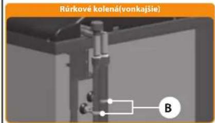
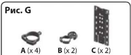
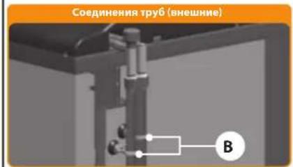
- Position the flow and suction pipes in your aquarium, making sure to fix them properly with the suitable accessories (Fig. G).
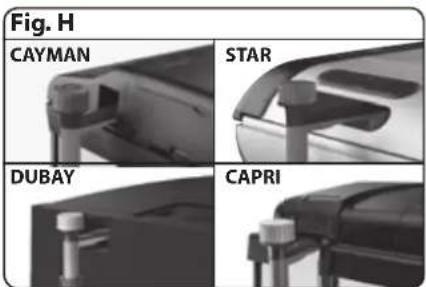
PLEASE NOTE: the FERPLAST aquariums are opportunely designed for the passage of tubes (Fig. H). - In the CAYMAN, DUBAI & CAPRI models there are easily removable rupture blocks present on the back of the cover.
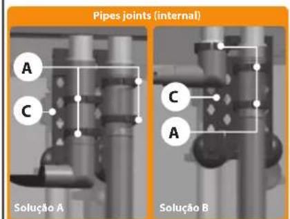
- In the STAR models, the rear grill vents can be easily removed to permit the passage of tubes. - We recommend that you position the flow and suction unit in the rear angles, in opposite positions, to avoid the formation of direct passages between the two. In fact, these passages could compromise the efficient functioning of your aquarium.
PLEASE NOTE: In the aquarium CAYMAN 60, because of the reduced amount of available space, it is not possible to utilize the "C" fittings in the left angle of the aquarium; therefore we recommend to position the suction on the right side and the flow on the left, entering directly into the flow with the flexible tube.
SUCTION TUBE
Position the "C" fittings with cap (Fig. C/9) on the aquarium and connect the semi-transparent tube towards the inside side of the aquarium; insert the height regulation tube (Fig. C/6), having already connected the grill on the bottom. Then regulate the position of the aquarium grill, keeping it approximately 3-4 cm from the bottom of the tank.
FLOW TUBES
Position the "C" fitting without cap (Fig. C/3) on the aquarium and connect the "L" fitting with or without extension (Fig. C/2), according to your needs. Then connect the spray-bar (Fig. C/1) or 360° rotary nozzle (Fig. C/5). Connect the flexible tubes to the filter tube fitting and the flow and suction unit, being careful not to invert the direction (IN from the filter towards the suction unit, OUT from the external filter towards the flow tube, Fig. F). After having inserted them into the seat, use the ferrules to fix them securely.
PLEASE NOTE: The flexible tubes are to be cut cleanly and at the correct length; they are then to be connected in a way that does not create horns (this also facilitates filter connection) or bending (which could compromise the water capacity).
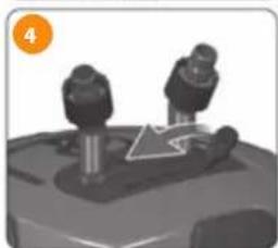
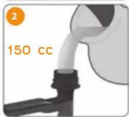
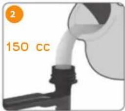
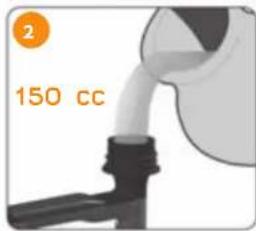
Starting the filter (self-priming system)
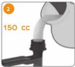
1 Make sure that the valve-opening lever is in the closed position.
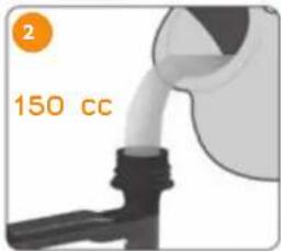
2 Open the cap located above the suction unit and pour a water cup (approximately 150 cc).
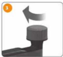
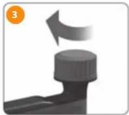
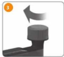
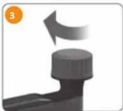
3 Re-close the cap carefully.
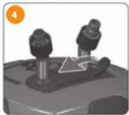
4 Open the filter valve using the appropriate lever. In this way, the system auto-starts.
5 Turn on the filter by connecting it to the electrical socket. Using the lever it is possible to regulate the flow and discharge of the water.
PLEASE NOTE:
Once the filter is started, make certain that there are no leaks. After a couple of hours of functioning, verify that the filter functions correctly and re-control that there are not any leaks. If the water does not flow in a satisfactory manner in the discharge tube, verify the connections of the tube and make certain that they are not obstructed or bent. By lightly shaking the filter it is possible to let out any air present inside.
Maintenance
Important: always unplug the filter from the electrical current before performing any maintenance.
Filter maintenance must be performed regularly, at least every 3-4 weeks, and always when there is an evident reduction in the flow level.
To perform maintenance:
- close the valve using the lever (Fig. I/5a);
- disconnect the filter from electricity;
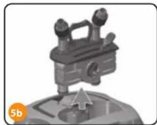
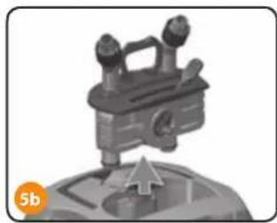
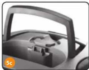
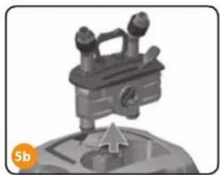
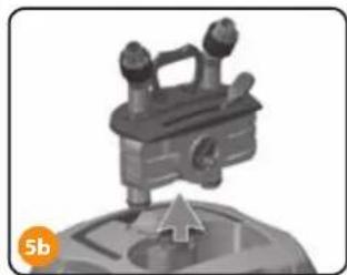
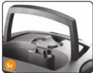
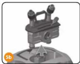
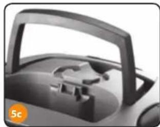
• after a few seconds, extract the valves group, using the release lever that facilitates the extraction (Fig. I/5b); - transport the filter towards the area where you will clean it, using the solid handle (Fig. I/5c);
- open the filter by moving the hooks (remember to raise the safety buttons);
- extract the ceramic cylinders basket. (PLEASE NOTE: it's not necessary to wash the biological filtration material, so they can retain their bacterial associations that keep them active);
- Rinse the mechanical and absorption filtration sponges, extracting them through the apposite basket handles:
- the mechanical filtration sponges must be replaced at least every 6 months; use only original BLUMEC replacements;
- The effect of the absorbent sponge runs out in the arc of 2-3 weeks; therefore, we recommend to replace it with original BLUCLEAR replacement or leave it in the filter with mechanical functioning; in any case, it must be replaced every 6 months;
- the absorbent sponge can also be replaced by other materials including activated carbon in grains BLUCARBON or zeolite BLUZEOLITE (it is advisable to position them with the provided bag);
- during periods of special therapeutic treatments, the absorbent sponge must be removed from the filter (to avoid a reduction in their beneficiary effects). Once this period is over, we recommend that you insert a new one.
- Clean the rotor and the shaft of the filter pump at least every 3-4 months:
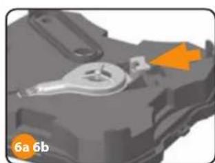
- remove the pump cover, pushing the tab towards the fan and pulling it off completely (Fig. I/6a-b);
- extract the rotor and shaft and clean them with a soft brush and tepid water (do not use detergent or abrasives);
- reassemble the pump by inverting the process, making certain that the ceramic shaft in tightly in its seat in the socket (be careful when handling it, as it is very fragile).
- Reassemble the filter; be careful to re-insert the filtration materials in the correct order: blue large pored sponge on the bottom, blue small pored sponge in the middle (only for 1100 and 1500), sponge with activated carbon on next, basket with ceramic cylinders on top.
- Position the filter near the tank and re-insert the valves group into its seat. Attention: if there is some water on the internal cover, before setting it into the filter, let the water go out by simply tilting the cover.
- If you have proceeded correctly, simply opening the valves and connecting the electricity will start the filter. In case, for any reason, the filter does not start-up, perform the procedure indicated in paragraph "Starting the filter".
Other maintenance activities:
- Seal: to guarantee an always-perfect filter hold, we recommend replacing the seals at least once a year, with the appropriate Ferplast Kit.
• Periodically clean the suction grill, verifying that it is never blocked. - Regularly re-clean the flexible tubes, so that algae or dirt do not reduce or impede the passage of water
natural_image
Illustration of two mechanical components with an arrow indicating motion (no text or symbols)SELF-PRIMING SYSTEM


natural_image
Close-up of a mechanical component with a curved arrow indicating rotation (no text or symbols)
natural_image
Mechanical component with two cylindrical parts and a triangular motion arrow (no text or symbols)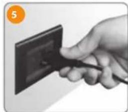
natural_image
Hand holding a black electrical outlet with a cable, no visible text or symbols
natural_image
Close-up of a mechanical lever mechanism with two stents and a directional arrow (no text or symbols)Fig. I
natural_image
Illustration of a mechanical device with three protrusions and a base, no visible text or symbols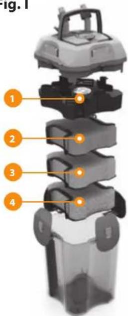

natural_image
Close-up of a car's front wheel and side door (no visible text or symbols)1 ceramic cylinders basket
2 absorbent sponge
3 large pored sponge
4 small pored sponge

natural_image
Close-up of a mechanical component with orange arrows indicating a specific part (no text or symbols visible)
natural_image
Close-up of a mechanical component with no visible text or symbolsReplacement parts and accessories
Every part of the BLUEXTREME filter is easily replaced. The replacement parts are available in the store where you purchased the filter. There are also numerous Ferplast accessories available, continuously updated, and useful for accommodating the aquarium for diverse needs. For the replacement of any component and to guarantee the maximum functioning and safety of your product, it is necessary to use only original Ferplast Parts. The assembly of unoriginal replacement parts renders the warranty null and void.
Warranty
Ferplast guarantees the BLUEXTREME filter and all of its components and accessories within the limits illustrated in the present clause and by the provisions of applicable law. The warranty is valid only for manufacturing defects and includes the repairs or replacement at no cost. The warranty is not valid for damage and/or defects caused by neglect, wear, use not conforming to the indications and warnings reported in this manual, accidents, mishandling, misuse, inappropriate repairs, and sales not accompanied by a sales receipt. The sponges, seals and filtration materials are excluded from the warranty.
PREMESSA
Fig. B


natural_image
Illustration of two mechanical components with a downward arrow, no text or symbols presentSELF-PRIMING SYSTEM Auto innesco


natural_image
Close-up of a mechanical component with a curved arrow indicating rotation (no text or symbols)
natural_image
3D rendered mechanical component with two cylindrical parts and a curved arrow indicating motion (no text or symbols)
natural_image
Hand holding a black electrical outlet with a cable, no visible text or symbols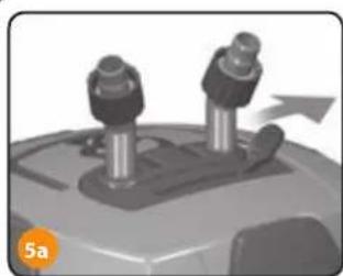
natural_image
Close-up of a mechanical component with two cylindrical parts and an arrow indicating motion (no text or symbols)Fig. I
natural_image
Illustration of a mechanical device with three protrusions and an arrow, no visible text or symbols
natural_image
Close-up of a car's front compartment showing the handle and seat (no visible text or symbols)natural_image
Close-up of a mechanical component with orange arrows indicating features (no readable text or symbols)
natural_image
Illustration of a mechanical device with orange arrows indicating motion or force (no text or symbols)Fig. B


natural_image
Illustration of two mechanical components with an arrow indicating motion (no text or symbols)
natural_image
3D rendered mechanical component with two cylindrical parts and a triangular pointer (no text or symbols)SELF-PRIMING SYSTEM
natural_image
Close-up of a mechanical component with a curved arrow indicating rotation (no text or symbols)
natural_image
Hand holding a black electrical outlet with a cable inserted (no text or symbols visible)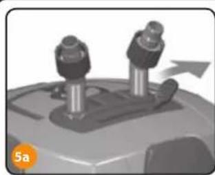
natural_image
Close-up of a mechanical component with two cylindrical parts and an arrow indicating motion (no text or symbols)
natural_image
Illustration of a mechanical device with three protrusions and a pointer, labeled '5b' in the corner (no text or symbols on the device itself)
natural_image
Close-up of a car's front wheel and dashboard (no visible text or symbols)Fig. I

natural_image
Close-up of a mechanical component with a highlighted section and orange arrow indicator (no readable text or symbols)
natural_image
Close-up of a mechanical component with orange arrows indicating direction (no visible text or symbols)Abb. B

natural_image
Illustration of two mechanical components with a downward arrow, no text or symbols presentSELF-PRIMING SYSTEM
Selbstansaugend
natural_image
Close-up of a mechanical component with a curved arrow indicating rotation (no text or symbols)
natural_image
3D rendered mechanical component with two protruding pins and a curved arrow indicating motion (no text or symbols)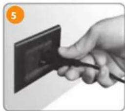
natural_image
Hand holding a black electrical outlet with a cable inserted (no visible text or symbols)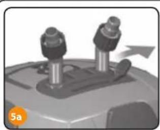
natural_image
Close-up of a mechanical component with two protruding pins and a directional arrow (no text or symbols)Abb. I
natural_image
Illustration of a mechanical device with a pointer and base, no visible text or symbols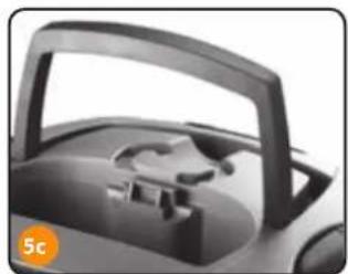
natural_image
Close-up of a car's front compartment showing the handle and seat (no text or symbols visible)natural_image
Mechanical component diagram showing a valve and housing with orange arrows indicating direction (no text or symbols)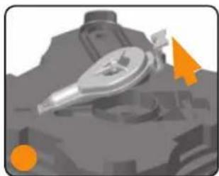
natural_image
Illustration of a mechanical component with orange arrows indicating direction (no text or symbols)DE VERPAKKING OPENMAKEN
In de verpakking van de BLUEXTREME-filter vindt u:
Afb. B


De filter opstarten (self-priming systeem)
natural_image
Illustration of two mechanical components with a downward arrow, no text or symbols presentSELF-PRIMING SYSTEM
Automisch in
werking stellend

natural_image
Close-up of a mechanical component with a curved arrow indicating rotation (no text or symbols)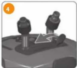
natural_image
3D rendered mechanical component with two protruding parts and a triangular load symbol (no text or labels)
natural_image
Hand holding a black electrical outlet with a cable, no visible text or symbols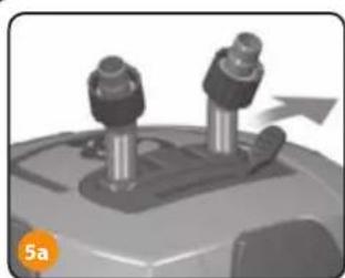
natural_image
Close-up of a mechanical device with two cylindrical components and an arrow indicating motion (no text or symbols)Afb.1

natural_image
Illustration of a mechanical device with three protrusions and an arrow, no visible text or symbols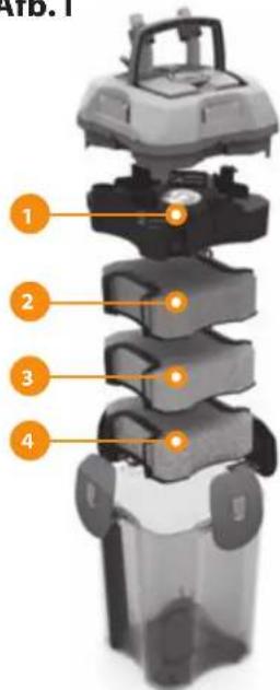

natural_image
Close-up of a car's front wheel and side door (no visible text or symbols)natural_image
Close-up of a mechanical component with a highlighted section and orange arrow (no readable text or symbols)
natural_image
Illustration of a futuristic spacecraft with a targeting gear and orange directional arrows (no text or symbols)Fig. B
natural_image
Illustration of two mechanical components with a downward arrow, no text or symbols presentSELF-PRIMING SYSTEM Auto encendido


natural_image
Close-up of a mechanical component with a curved arrow indicating rotation (no text or symbols)
natural_image
3D rendered mechanical component with two cylindrical parts and a curved arrow indicating motion (no text or symbols)
natural_image
Hand holding a black electrical outlet with a cable inserted (no text or symbols visible)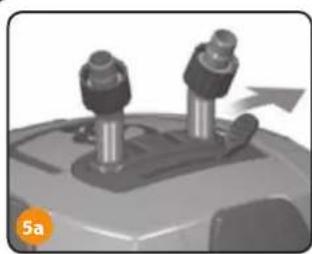
natural_image
Close-up of a mechanical device with two cylindrical components and an arrow indicating motion (no text or symbols)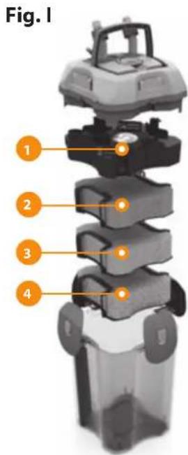

natural_image
Illustration of a mechanical device with three protrusions and an arrow pointing upward (no text or symbols)
natural_image
Close-up of a car's front wheel and dashboard (no visible text or symbols)natural_image
Close-up of a mechanical component with a highlighted section and orange arrow (no readable text or symbols)
natural_image
Illustration of a mechanical device with orange arrows indicating direction (no text or symbols)Garantía

Fig. B


natural_image
Illustration of two mechanical components with a downward arrow, no text or symbols present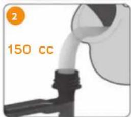
natural_image
3D-rendered mechanical component with two protruding parts and a triangular motion arrow (no text or symbols)natural_image
Close-up of a mechanical component with a curved arrow indicating rotation (no text or symbols)
natural_image
Hand holding a black cable inserted into an electrical outlet (no text or symbols visible)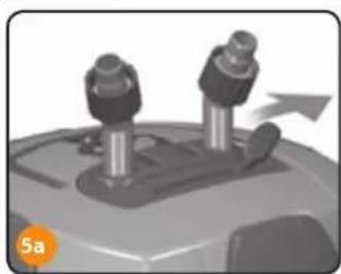
natural_image
Close-up of a mechanical device with two cylindrical components and an arrow indicating motion (no text or symbols)
natural_image
Illustration of a mechanical device with three protrusions and an arrow pointing to a base (no text or symbols)
natural_image
Close-up of a car's front wheel and dashboard (no visible text or symbols)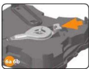
natural_image
Mechanical component diagram showing a valve and housing with orange arrows indicating direction (no text or symbols)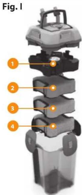
1 Cesto de cilindros de cerâmica
2 Esponja absorvente
3 Esponja grande de poros
4 Esponja pequena de poros
natural_image
Illustration of a futuristic spacecraft or spacecraft with a metallic helmet and orange directional arrows (no text or symbols)natural_image
Exterior view of a transparent cylindrical water heater with two protruding ports (no text or symbols visible)Otvorenie balíka
Vo vnútri balenia BLUEXTREME nájdete:
Orb. B


Príprava akvária
natural_image
Illustration of two mechanical components with a downward arrow, no text or symbols presentSAMOSPÚŠTACÍ SYSTÉM


natural_image
Close-up of a mechanical component with a curved arrow indicating motion (no text or symbols)
natural_image
3D rendered mechanical component with two cylindrical parts and a triangular guide arrow (no text or symbols)
natural_image
Hand holding a black electrical outlet with a cable inserted (no text or symbols visible)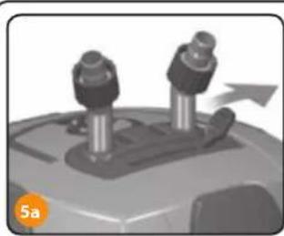
natural_image
Close-up of a mechanical device with two cylindrical components and an arrow indicating motion (no text or symbols)Orb.1
natural_image
Illustration of a mechanical device with three protrusions and an arrow pointing to a base (no text or symbols)
natural_image
Close-up of a car's front wheel and dashboard (no visible text or symbols)natural_image
Close-up of a mechanical component with orange arrows indicating a specific feature (no text or symbols visible)
natural_image
Illustration of a mechanical device with orange arrows indicating direction (no text or symbols)natural_image
Exterior view of a transparent cylindrical water dispenser with two protruding ports (no text or symbols visible)Otevření balíku
Orb. B


Příprava akvária

natural_image
Illustration of two mechanical components with a downward arrow, no text or symbols presentSAMOSPOUŠTĚCÍ SYSTÉM
natural_image
Close-up of a mechanical component with a curved arrow indicating rotation (no text or symbols)
natural_image
3D rendered mechanical component with two cylindrical components and a triangular guide (no text or symbols)
natural_image
Hand holding a black electrical outlet with a cable, no visible text or symbols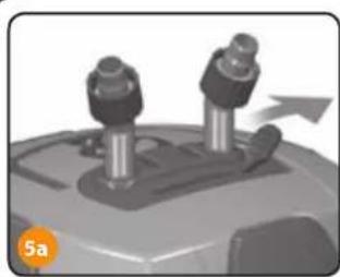
natural_image
Mechanical component with two bolts and a directional arrow, no visible text or symbolsOrb.1
natural_image
3D rendered mechanical component with no visible text or symbols

natural_image
Close-up of a car's front wheel and side door (no visible text or symbols)natural_image
Mechanical component diagram showing a lever and housing with orange arrows indicating specific parts (no text or symbols present)
natural_image
Close-up of a mechanical component with no visible text or symbolsnatural_image
Exterior view of a transparent cylindrical water heater with two protruding ports (no text or symbols visible)1 ábra
natural_image
Simple line drawing of a power outlet connected to a vertical pipe with a downward arrow indicating flow or discharge (no text or symbols)A BLUEXTREME technikai adatai
B ábra

natural_image
Illustration of two mechanical components with a downward arrow, no text or symbols presentÖNINDÍTÓ RENDSZER

natural_image
Close-up of a mechanical component with a curved arrow indicating motion (no text or symbols)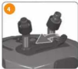
natural_image
3D rendered mechanical component with two protruding pins and a triangular motion arrow (no text or symbols)
natural_image
Hand holding a black cable inserted into an electrical outlet (no text or symbols visible)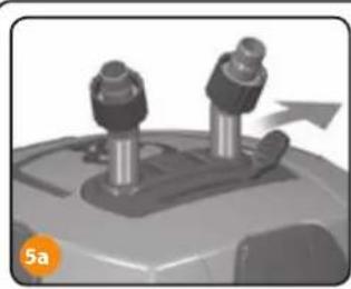
natural_image
Close-up of a mechanical device with two cylindrical components and an arrow indicating motion (no text or symbols)I ábra

natural_image
Illustration of a mechanical device with three protrusions and a pointer, no visible text or symbols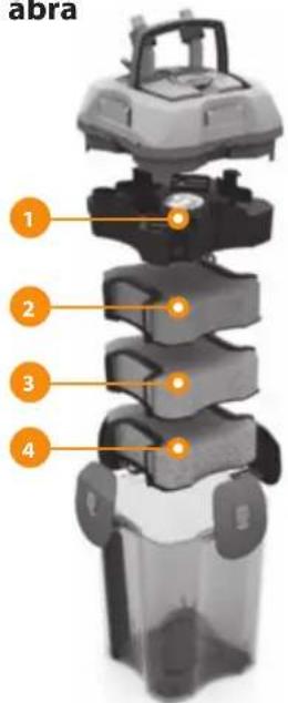

natural_image
Close-up of a car's front wheel and side door (no visible text or symbols)natural_image
Mechanical component diagram showing a valve and housing with orange arrows indicating direction (no text or symbols)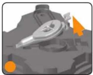
natural_image
3D rendered mechanical component with orange directional arrows (no text or symbols)
Bild B
natural_image
Illustration of two mechanical components with a downward arrow, no text or symbols present

natural_image
3D rendered mechanical component with two protruding parts and a triangular guide mechanism (no text or symbols)SJÄLVSUGANDE SYSTEM

natural_image
Close-up of a mechanical component with a curved arrow indicating motion (no text or symbols)
natural_image
Hand holding a black electrical outlet with a cable inserted (no text or symbols visible)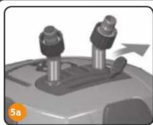
natural_image
Close-up of a mechanical device with two cylindrical components and an arrow indicating motion (no text or symbols)
natural_image
Illustration of a mechanical device with three protrusions and a base, no visible text or symbols
natural_image
Close-up of a car's front wheel and side door (no visible text or symbols)Fig. I

1 keramiska cylinderkorgar
2 absorberande svamp
3 svamp med stora porer
4 svamp med små porer
natural_image
Mechanical component diagram showing a lever and housing with an orange arrow indicating direction (no text or symbols)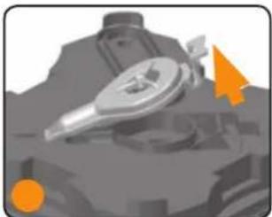
natural_image
Close-up of a mechanical component with no visible text or symbols
Fig. B


natural_image
Illustration of two mechanical components with an arrow indicating motion (no text or symbols)

natural_image
3D rendered mechanical component with two protruding parts and a triangular guide mechanism (no text or symbols)DET
SELVSPÄNDENDE
SYSTEM

natural_image
Close-up of a mechanical component with a curved arrow indicating motion (no text or symbols)
natural_image
Hand holding a black electrical outlet with a cable inserted (no text or symbols visible)
natural_image
Close-up of a mechanical device with two cylindrical components and an arrow indicating motion (no text or symbols)
natural_image
Illustration of a mechanical device with three protrusions and a base, no visible text or symbols
natural_image
Close-up of a car's front wheel and side door (no visible text or symbols)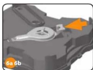
natural_image
Close-up of a mechanical component with orange arrow indicating a specific part (no text or symbols visible)Fig. I

1 kurv med keramiske cylindere
2 absorberende svamp
3 svamp med store porer
4 svamp med små porer

natural_image
Close-up of a mechanical component with no visible text or symbolsnatural_image
Exterior view of a transparent cylindrical water heater with two protruding pipes (no text or symbols visible)Рис. I
natural_image
Simple line diagram showing a power outlet connected to a vertical pipe with a downward arrow indicating flow or direction (no text or symbols)Рис. В

natural_image
Illustration of two mechanical components with an arrow indicating motion (no text or symbols)ПУСК НАСОСА
natural_image
Close-up of a mechanical component with a curved arrow indicating motion (no text or symbols)
natural_image
Mechanical component with two cylindrical parts mounted on a base, no visible text or symbols
natural_image
Hand holding a black pen touching a dark electrical outlet (no text or symbols visible)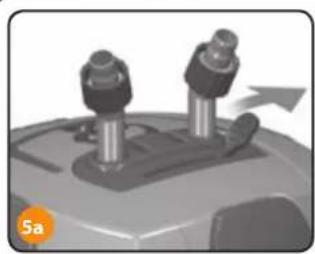
natural_image
Close-up of a mechanical device with two cylindrical components and an arrow indicating motion (no text or symbols)Рис. I

natural_image
Illustration of a mechanical device with three protrusions and an arrow pointing to a base (no text or symbols)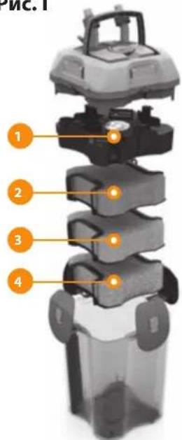
natural_image
Close-up of a black plastic car interior with handle and seat (no visible text or symbols)natural_image
Close-up of a mechanical component with orange arrows indicating features (no readable text or symbols)
natural_image
Illustration of a mechanical component with orange arrows indicating direction (no text or symbols)Запасные детали
rys B

ZAKŁADANIE AKWARIUM
natural_image
Illustration of two mechanical components with a downward arrow, no text or symbols present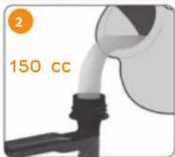

natural_image
3D rendered mechanical component with two protruding parts and a triangular guide mechanism (no text or symbols)SELF-PRIMING SYSTEM
natural_image
Close-up of a mechanical component with a curved arrow indicating rotation (no text or symbols)
natural_image
Hand holding a black electrical outlet with a cable inserted (no text or symbols visible)
natural_image
Close-up of a mechanical device with two cylindrical components and an arrow indicating motion (no text or symbols)
natural_image
Illustration of a mechanical device with three protrusions and a base, no visible text or symbols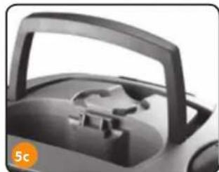
natural_image
Close-up of a car's front wheel and side door (no visible text or symbols)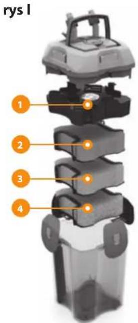
natural_image
Close-up of a mechanical component with orange arrow indicating a specific part (no text or symbols visible)
natural_image
Close-up of a mechanical component with no visible text or symbolsCZEŚCI ZAMIENNE I AKCESORIA
natural_image
Black-and-white underwater photo of a striped fish head and its mouth, surrounded by palm trees (no text or symbols visible)
IMPORTANT
Within the European Union, a crossed-out wheelie bin symbol on the product, documentation or packaging indicates that the product cannot be disposed of in the regular household waste stream, in compliance with EU Directive 2012/19/EC and with current local regulations. The product must be disposed of at recycling centres or authorised waste disposal centres for electrical and electronic equipment, in accordance with current legislation in the country where the product is found. Incorrect disposal of this type of waste can have a negative impact on the environment and human health, caused by the potentially hazardous substances produce by electrical and electronic equipment. Correct disposal of these products will also contribute to the efficient use of natural resources. Further information is available from the product retailer, the competent local authorities and national manufacturer's organisations.
IMPORTANTE

- PRELIMINARY WARNINGS
- OPENING THE PACKAGE
- Inside the BLUEXTREME package you will find:
- BLUEXTREME:
- discover all of its impressive qualities
- Filter handle
- Valve release lever
- Valve opening lever (safety system)
- Tube fittings with ferrule
- Valves group
- Hooks
- Tank seal
- Pre-chamber seal
- Ceramic cylinders basket
- Water passage tube
- Filtration material basket
- Suction tube
- Flexible tube
- Fig. A
- Fig. C
- Setting up the aquarium
- Install the external filter as described below
- Preparation and installation of the filter
- FLOW TUBES
- Starting the filter (self-priming system)
- PLEASE NOTE:
- Maintenance
- To perform maintenance:
- Other maintenance activities:
- Replacement parts and accessories
- Warranty
- PREMESSA
- SELF-PRIMING SYSTEM
- DE VERPAKKING OPENMAKEN
- In de verpakking van de BLUEXTREME-filter vindt u:
- De filter opstarten (self-priming systeem)
- Garantía
- Otvorenie balíka
- Vo vnútri balenia BLUEXTREME nájdete:
- Príprava akvária
- Otevření balíku
- Příprava akvária
- A BLUEXTREME technikai adatai
- SJÄLVSUGANDE SYSTEM
- Запасные детали
- ZAKŁADANIE AKWARIUM
- CZEŚCI ZAMIENNE I AKCESORIA
- IMPORTANT
- IMPORTANTE
Brand : Ferplast
Model : Bluextreme 1100
Category : Aquarium