546534 - Saw SILVERLINE - Free user manual and instructions
Find the device manual for free 546534 SILVERLINE in PDF.


User questions about 546534 SILVERLINE
0 question about this device. Answer the ones you know or ask your own.
Ask a new question about this device
Download the instructions for your Saw in PDF format for free! Find your manual 546534 - SILVERLINE and take your electronic device back in hand. On this page are published all the documents necessary for the use of your device. 546534 by SILVERLINE.
USER MANUAL 546534 SILVERLINE
natural_image
Mechanical cutting cutter with blade and workpiece, no visible text or symbols
text_image
DIY SERIES


text_image
Technical diagram of a mechanical device with numbered parts, likely an electric motor or cutting tool assembly.English ......08
Français ......16
Deutsch......26
Español......36
Italiano......44
Nederlands .....52
Polski ......60
A
natural_image
Close-up of a hand operating a mechanical power tool with a downward arrow indicating motion (no text or symbols visible)B
natural_image
Close-up of hands assembling or adjusting mechanical components (no visible text or symbols)C

natural_image
Close-up of a hand operating a cutting tool with a metal bracket (no visible text or symbols)D
natural_image
Close-up of a hand operating a mechanical clamp or cutting tool (no visible text or symbols)E

natural_image
Close-up of a mechanical tool with a metallic handle and lever mechanism (no visible text or symbols)F
natural_image
Close-up of a hand holding two black tool tips with arrows pointing outward, next to a mechanical component (no visible text or symbols)G
natural_image
Close-up of a hand using a mechanical tool to adjust or install a component, no visible text or symbolsH
natural_image
Close-up of a mechanical clamp or fixture with hands operating it, no visible text or symbols1
natural_image
Close-up of a mechanical component with a curved black knob and a metallic handle, mounted on a wooden surface (no visible text or symbols)J
natural_image
Close-up of a mechanical assembly with a hand adjusting components (no visible text or symbols)K
natural_image
Person using a cutting tool on a metal workbench, no visible text or symbolsL
natural_image
Close-up of a hand adjusting a car wheel component with a magnified inset showing the finger detail (no text or symbols visible)M
natural_image
Close-up of a mechanical component with a tool inserted, showing rotational motion and dimension (no text or symbols visible)N
natural_image
Close-up of a mechanical component with a metallic part and internal components (no visible text or symbols)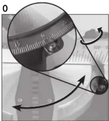
natural_image
Close-up of a mechanical component with circular motion arrows and measurement scale (no readable text or symbols)P
text_image
45°Q
natural_image
Close-up of a mechanical assembly with arrows indicating motion or force direction (no visible text or symbols)R
natural_image
Close-up of a mechanical assembly with a tool inserted, no visible text or symbolsS
natural_image
Close-up of a robotic arm cutting metal components with a 45-degree angle marker (no text or symbols on the diagram itself)T
natural_image
Close-up of a mechanical component with visible parts and a circular feature (no text or symbols)U
natural_image
Close-up of a mechanical device with four arms and a central hub, viewed from above (no visible text or symbols)V
natural_image
Close-up of a mechanical device with a central component and directional arrows indicating movement or force (no visible text or symbols)W
natural_image
Close-up of a hand adjusting a mechanical component with tools and components (no visible text or symbols)X
natural_image
Close-up of a hand using a tool to adjust or install a mechanical component (no visible text or symbols)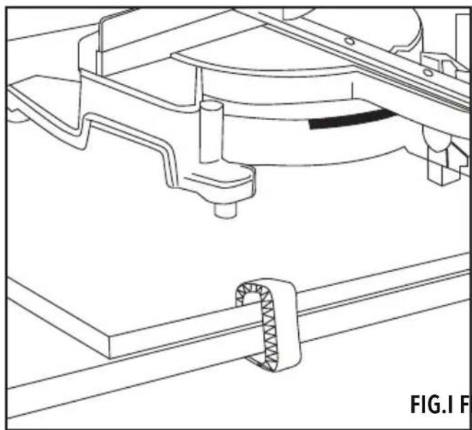
natural_image
Technical line drawing of a mechanical assembly with no visible text or symbolsFIG.1 FIG.1
natural_image
Pure electrical circuit lines without any symbols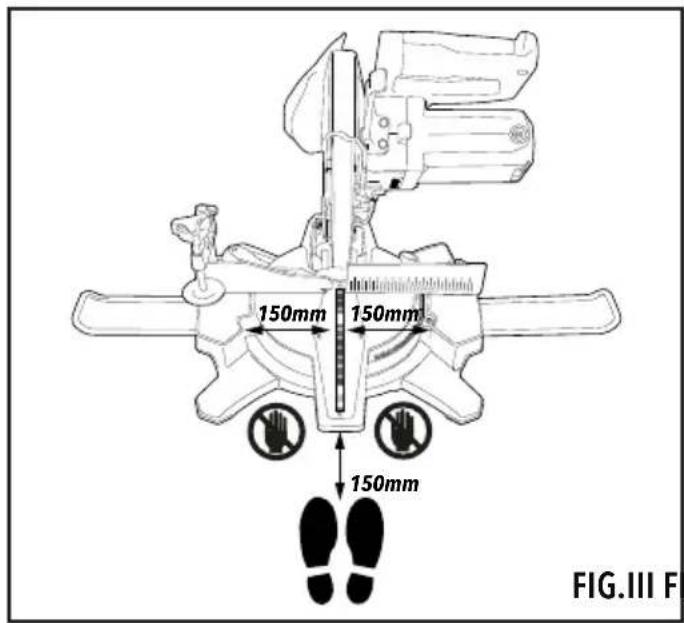
text_image
150mm 150mm 150mm FIG.III FFIG.III FIG.IV
natural_image
Technical line drawing of a mechanical device with a curved base and lever mechanism (no text or symbols)Introduction
Thank you for purchasing this Silverline tool. This manual contains information necessary for safe and effective operation of this product. This product has unique features and, even if you are familiar with similar products, it is necessary to read this manual carefully to ensure you fully understand the instructions. Ensure all users of the tool read and fully understand this manual.
Description of Symbols
The rating plate on your tool may show symbols. These represent important information about the product or instructions on its use.

Wear hearing protection.
Wear eye protection.
Wear breathing protection.
Wear head protection.

Wear hand protection.

Read instruction manual.

Toxic fumes or gases!

LASER warning!

Be aware of kickback!

Warning: Sharp blades or teeth!

DO NOT use in rain or damp environments!

Class II construction (double insulated for additional protection)

Environmental Protection
Waste electrical products should not be disposed of with household waste. Please recycle where facilities exist. Check with your local authority or retailer for recycling advice.

Conforms to relevant legislation and safety standards.

Caution!

Always disconnect from the power supply when adjusting, changing accessories, cleaning, carrying out maintenance and when not in use!

Do not touch the blades before the machine is disconnected from the supply and the blades have come to complete stop.

Dust extraction required or recommended
Technical Abbreviations Key
| V Volts | |
| ~, AC Alternating current | |
| A, mA Ampere, milli-Amp | |
| n0 No load speed | |
| ° Degrees | |
| ∅ Diameter | |
| Hz Hertz | |
| W, kW Watt, kilowatt | |
| /min or min ^-1 | Operations per minute |
| rpm Revolutions per minute | |
| dB(A) Decibel sound level (A weighted) |
Specification
| Voltage: | 230V~50Hz |
| Power: | 1450W |
| No load speed: | 5000rpm |
| Max depth of cut: | 62mm |
| Max blade size: | ∅210mm |
| Blade bore: | ∅30mm |
| Supplied blade: | ∅210 x 30 x 2.8mm 24T |
| Mitre table angles: | 45 to +45° |
| Bevel cuts: | 0-45° |
| Straight cut: | |
| 0° mitre x 0° bevel. | 170 x 60mm |
| Mitre cut: | |
| 45° (L&R) x 0° | 120 x 60mm |
| Bevel cut: | |
| 0° mitre x bevel (L) 45° | 170 x 34mm |
| 45° mitre (L&R) x bevel (L) 45° | 120 x 34mm |
| Laser Class: | II |
| Laser Wavelength: | 650nm |
| Laser Output power: | ≤ 1mW |
| Power cord length: | 2m |
| Protection class: | |
| Ingress protection: | IP20 |
| Dimensions (L x W x H): | 380 x 340 x 420mm |
| Weight: | 7.23kg |
| As part of our ongoing product development, specifications of Silverline products may alter without notice. | |
| Sound and vibration information: | |
| Sound pressure L _TM | 96.54dB(A) |
| Sound power L _MAX | 109.54dB(A) |
| Uncertainty K | 3dB |
| The sound intensity level for the operator may exceed 85dB(A)and sound protection measures are necessary. | |

WARNING: Always wear ear protection where the sound level exceeds 85dB(A) and limit me of exposure if necessary. If sound levels are uncomfortable, even with ear protection, stop the tool immediately and check the ear protection is correctly fitted and provides the correct of sound attenuation for the level of sound produced by your tool.

WARNING: User exposure to tool vibration can result in loss of sense of touch, numbness, ting and reduced ability to grip. Long-term exposure can lead to a chronic condition. If necessary, the length of time exposed to vibration and use anti-vibration gloves. Do not operate the tool and below a normal comfortable temperature, as vibration will have a greater effect. Use the tools provided in the specification relating to vibration to calculate the duration and frequency operating the tool.
Sound and vibration levels in the specification are determined according to international standards. The figures represent normal use for the tool in normal working conditions. A poorly maintained, incorrectly assembled, or misused tool, may produce increased levels of noise and vibration. www.osha.europa.eu provides information on sound and vibration levels in the workplace that may be useful to domestic users who use tools for long periods of time.
Carefully read and understand this manual and any label attached to the tool before use. Keep these instructions with the product for future reference. Ensure all persons who use this product are fully acquainted with this manual.
Even when used as prescribed it is not possible to eliminate all residual risk factors. Use with caution. If you are at all unsure of the correct and safe manner in which to use this tool, do not attempt to use it.
General Power Tool Safety Warnings

WARNING: Read all safety warnings, instructions, illustrations and specifications
provided with this power tool. Failure to follow all instructions listed below may result in electric shock, fire and/or serious injury.
Save all warnings and instructions for future reference.
The term "power tool" in the warnings refers to your mains-operated (corded) power tool or battery-operated (cordless) power tool.
1) Work area safety
a) Keep work area clean and well lit. Cluttered or dark areas invite accidents.
b) Do not operate power tools in explosive atmospheres, such as in the presence of flammable liquids, gases or dust. Power tools create sparks which may ignite the dust or fumes.
c) Keep children and bystanders away while operating a power tool. Distractions can cause you to lose control.
2) Electrical safety
a) Power tool plugs must match the outlet. Never modify the plug in any way. Do not use any adapter plugs with earthed (grounded) power tools. Unmodified plugs and matching outlets will reduce risk of electric shock.
b) Avoid body contact with earthed or grounded surfaces, such as pipes, radiators, ranges and refrigerators. There is an increased risk of electric shock if your body is earthed or grounded.
c) Do not expose power tools to rain or wet conditions. Water entering a power tool will increase the risk of electric shock.
d) Do not abuse the cord. Never use the cord for carrying, pulling or unplugging the power tool. Keep cord away from heat, oil, sharp edges or moving parts. Damaged or entangled cords increase the risk of electric shock.
e) When operating a power tool outdoors, use an extension cord suitable for outdoor use. Use of a cord suitable for outdoor use reduces the risk of electric shock.
f) If operating a power tool in a damp location is unavoidable, use a residual current device (RCD) protected supply. Use of an RCD reduces the risk of electric shock.
3) Personal safety
a) Stay alert, watch what you are doing and use common sense when operating a power tool. Do not use a power tool while you are tired or under the influence of drugs, alcohol or medication. A moment of inattention while operating power tools may result in serious personal injury.
b) Use personal protective equipment. Always wear eye protection. Protective equipment such as a dust mask, non-skid safety shoes, hard hat or hearing protection used for appropriate conditions will reduce personal injuries.
c) Prevent unintentional starting. Ensure the switch is in the OFF-position before connecting to power source and/or battery pack, picking up or carrying the tool. Carrying power tools with your finger on the switch or energising power tools that have the switch ON invites accidents.
d) Remove any adjusting key or wrench before turning the power tool ON. A wrench or a key left attached to a rotating part of the power tool may result in personal injury.
e) Do not overreach. Keep proper footing and balance at all times. This enables better control of the power tool in unexpected situations.
f) Dress properly. Do not wear loose clothing or jewellery. Keep your hair and clothing away from moving parts. Loose clothes, jewellery or long hair can be caught in moving parts.
g) If devices are provided for the connection of dust extraction and collection facilities, ensure these are connected and properly used. Use of dust collection can reduce dust-related hazards.
h) Do not let familiarity gained from frequent use of tools allow you to become complacent and ignore tool safety principles. A careless action can cause severe injury within a fraction of a second.
4) Power tool use and care
a) Do not force the power tool. Use the correct power tool for your application. The correct power tool will do the job better and safer at the rate for which it was designed.
b) Do not use the power tool if the switch does not turn it ON and OFF. Any power tool that cannot be controlled with the switch is dangerous and must be repaired.
c) Disconnect the plug from the power source and/or remove the battery pack, if detachable, from the power tool before making any adjustments, changing accessories, or storing power tools. Such preventive safety measures reduce the risk of starting the power tool accidentally.
d) Store idle power tools out of the reach of children and do not allow persons unfamiliar with the power tool or these instructions to operate the power tool. Power tools are dangerous in the hands of untrained users.
c) Maintain power tools and accessories. Check for misalignment or binding of moving parts, breakage of parts and any other condition that may affect the power tool's operation. If damaged, have the power tool repaired before use. Many accidents are caused by poorly maintained power tools.
f) Keep cutting tools sharp and clean. Properly maintained cutting tools with sharp cutting edges are less likely to bind and are easier to control.
g) Use the power tool, accessories and tool bits, etc. in accordance with these instructions, taking into account the working conditions and the work to be performed. Use of the power tool for operations different from those intended could result in a hazardous situation.
h) Keep handles and grasping surfaces dry, clean and free from oil and grease. Slippery handles and grasping surfaces do not allow for safe handling and control of the tool in unexpected situations.
5)
a) Service Have your power tool serviced by a qualified repair person using only identical replacement parts. This will ensure that the safety of the power tool is maintained.
Specific Safety
Mitre Saw Safety
WARNING: Before connecting a tool to a power source (mains switch power point receptacle, outlet, etc.) be sure that the voltage supply is the same as that specified on the rating label of the tool. A power source with a voltage greater than that specified for the tool can result in serious injury to the user, and damage to the tool. If in doubt, do not plug in the tool. Using a power source with a voltage less than the nameplate rating is harmful to the motor.

WARNING!
- Hold the power tool by insulated gripping surfaces only, when performing an operation where the cutting tool may contact its own cord. Contact with a "live" wire will also make exposed metal parts of the power tool "live" and could give the operator electric shock.
- Always use blades with correct size and shape (diamond versus round) of arbour holes. Blades that do not match the mounting hardware of the saw will run eccentrically, causing loss of control.
- Never use damaged or incorrect blade washers or bolt. The blade washers and bolt were specially designed for your saw, for optimum performance and safety of operation.
- Keep hands away from cutting area and the blade.
IMPORTANT: If you are unsure about operating this tool after reading these instructions, please seek additional training.
a) Do not allow anyone under the age of 18 years to operate this saw
b) When operating the saw, use safety equipment including safety goggles or shield, ear protection, dust mask and protective clothing including safety gloves
c) Power tools may produce vibration. Vibration can cause disease. Gloves may help to maintain good blood circulation in the fingers. Hand-held tools should not be used for long periods without a break
d) Whenever possible, use a vacuum dust extraction system to control dust/waste
c) Do not attempt to cut material thicker than detailed in the Specifications section of this manual
f) Mitre saws are not designed for general cutting of firewood. Always ensure wood is dry with suitable flat surfaces, so it is securely held on the mitre table and fence
g) Only guide the saw blade against the workpiece when the tool is switched on. Otherwise there is a risk of kickback when the blade becomes wedged in the workpiece
h) Adjust the cutting depth to the thickness of the workpiece
i) Never remove dust, chips or waste by hand close to the blade. Ensure the tool is unpowered and use a suitable brush
j) Only use saw blades recommended by the manufacturer that conform to EN 847-1 or equivalent standard in your country
k) Keep rags, cloths and string away from the work area and ensure the operator's clothing has no loose strands of material that could become caught in the rotating blade, causing injury. Gloves worn by the operator must not have loose strands
1) Ensure the mitre saw is operated without risk of items stored above falling onto the tool. Vibration of the tool may cause nearby stored items to move
m) Keep saw blades not fitted to the tool in a suitable container to protect against cuts - especially when carrying
n) Always ensure the saw blade is suitable for the material being cut and that the maximum rpm of the blade is not exceeded by the maximum no load speed of the saw
o) When using blades with a larger bore than the mitre saw spindle ensure the correct size bore spacer (spindle ring) is used
p) When transporting the saw, ensure its own transport handle is used (not the operating handle) and that the saw is in the locked down position
q) Do not remove cut-off material or swap the workpiece without first returning the saw head to the top position with the guard closed
r) Ensure work is correctly supported. Large panels may sag under their own weight and bind the saw blade. Supports must be placed under the panel on both sides, close to the line of cut and near the edge of the panel
s) Ensure all supports and power cables are completely clear of the cutting path
1) Always secure the workpiece to a stable platform, ensuring body exposure is minimised, avoiding blade binding, or loss of control
u) Do not stand in line with the saw blade of the mitre saw in use. Stand to the side to avoid possible kickback
v) Note the direction of rotation of the motor and the blade
w) Inspect the workpiece and remove all nails and other embedded objects prior to starting work
x) Do not apply any sideways or twisting force to the blade whilst cutting
y) If a cut does not extend to the edge of the workpiece, or if the blade binds in the cut, allow the blade to come to a complete stop and lift the saw out of the workpiece
z) Do not attempt to free a jammed blade before first disconnecting the machine from power
- Beware of projected waste. In some situations, waste material may be projected at speed from the cutting tool. It is the user's responsibility to ensure that other people in the work area are protected from the possibility of projected waste
- If you are interrupted when operating the saw, complete the process and switch off before diverting your attention
- Check the lower guard for proper closing before each use. Do not operate the saw if the lower guard does not move freely and close instantly. Never clamp or tie the lower guard into the open position. If the saw is accidentally dropped, the lower guard may be bent. Raise the lower guard with the retracting handle and make sure it moves freely and does not touch the blade or any other part, in all angles and depths of cut
- Never operate the saw without the guards fitted
- Periodically check that all nuts, bolts and other fixings have not loosened, tighten where necessary
- Do not use blades of High Speed Steel (HSS blades)
- If the table insert is damaged or worn, have it replaced by a power tool repairer.
The tool must be used only for its prescribed purpose. Any use other than those mentioned in this manual will be considered a case of misuse. The user, and not the manufacturer, shall be liable for any damage or injury resulting from such cases of misuse.
The manufacturer shall not be liable for any modifications made to the tool nor for any damage resulting from such modifications. Even when the tool is used as prescribed it is not possible to eliminate all residual risk factors.
Further safety instructions for all saws
Kickback causes & related warnings
- kickback is a sudden reaction to a pinched, bound or misaligned saw blade, causing an uncontrolled saw to lift up and out of the workpiece toward the operator;
- when the blade is pinched or bound tightly by the kerf closing down, the blade stalls and the motor reaction drives the unit rapidly back toward the operator;
- if the blade becomes twisted or misaligned in the cut, the teeth at the back edge of the blade can dig into the top surface of the wood causing the blade to climb out of the kerf and jump back toward the operator.
Kickback is the result of saw misuse and/or incorrect operating procedures or conditions and can be avoided by taking proper precautions as given below.
a) Maintain a firm grip with both hands on the saw and position your arms to resist kickback forces. Position your body to either side of the blade, but not in line with the blade. Kickback could cause the saw to jump backwards, but kickback forces can be controlled by the operator if proper precautions are taken.
b) When blade is binding, or when interrupting a cut for any reason, release the trigger and hold the saw motionless in the material until the blade comes to a complete stop. Never attempt to remove the saw from the work or pull the saw backward while the blade is in motion or kickback may occur. Investigate and take corrective actions to eliminate the cause of blade binding.
c) When restarting a saw in the workpiece, centre the saw blade in the kerf and check that saw teeth are not engaged into the material. If saw blade is binding, it may walk up or kickback from the workpiece as the saw is restarted.
d) Support large panels to minimise the risk of blade pinching and kickback. Large panels tend to sag under their own weight. Supports must be placed under the panel on both sides, near the line of cut and near the edge of the panel.
e) Do not use dull or damaged blades. Unsharpened or improperly set blades produce narrow kerf causing excessive friction, blade binding and kickback.
f) Blade depth and bevel adjusting locking levers must be tight and secure before making
cut. If blade adjustment shifts while cutting, it may cause binding and kickback.
g) Use extra caution when sawing into existing walls or other blind areas. The protruding blade may cut objects that can cause kickback.
Lower guard function
a) Check lower guard for proper closing before each use. Do not operate the saw if lower guard does not move freely and close instantly. Never clamp or tie the lower guard into the open position. If saw is accidentally dropped, lower guard may be bent. Raise the lower guard with the retracting handle and make sure it moves freely and does not touch the blade or any other part, in all angles and depths of cut.
b) Check the operation of the lower guard spring. If the guard and the spring are not operating properly, they must be serviced before use. Lower guard may operate sluggishly due to damaged parts, gummy deposits, or a build-up of debris.
c) Lower guard may be retracted manually only for special cuts such as "plunge cuts" and "compound cuts". Raise lower guard by retracting handle and as soon as blade enters the material, the lower guard must be released. For all other sawing, the lower guard should operate automatically.
d) Always observe that the lower guard is covering the blade before placing saw down on bench or floor. An unprotected, coasting blade will cause the saw to walk backwards, cutting whatever is in its path. Be aware of the time it takes for the blade to stop after switch is released.
Guard function
a) Check guard for proper closing before each use. Do not operate the saw if guard does not move freely and enclose the blade instantly. Never clamp or tie the guard so that the blade is exposed. If saw is accidentally dropped, guard may be bent. Check to make sure that guard moves freely and does not touch the blade or any other part, in all angles and depths of cut.
b) Check the operation and condition of the guard return spring. If the guard and the spring are not operating properly, they must be serviced before use. Guard may operate sluggishly due to damaged parts, gummy deposits, or a build-up of debris.
c) Assure that the base plate of the saw will not shift while performing the "plunge cut" when the blade bevel setting is not at 90°. Blade shifting sideways will cause binding and likely kick back.
d) Always observe that the guard is covering the blade before placing saw down on bench or floor. An unprotected, coasting blade will cause the saw to walk backwards, cutting whatever is in its path. Be aware of the time it takes for the blade to stop after switch is released.
Laser Safety
The laser used in this device is a Class 2 laser with maximum power of ≤1mW and a wavelength of 400-700nm.
These lasers do not normally present an optical hazard, although staring at the beam may cause flash blindness.
WARNING: Avoid direct eye contact.
A hazard may exist if you deliberately stare into the beam, please observe all safety rules as follows:
- The laser shall be used and maintained in accordance with the manufacturer's instructions
- Do not switch on the laser light until the tool is ready to cut
- Never aim the beam at any person, and particularly not into the eyes of any person or animal, or any object other than the workpiece
- Always ensure the laser beam is aimed at a sturdy workpiece without reflective surfaces. i.e. wood or rough-coated surfaces are acceptable. Reflective sheet steel or similar is not suitable for laser use as the reflective surface could direct the beam back at the operator
Do not change the laser light assembly. Repairs must only be carried out by the laser manufacturer or an authorised agent. DO NOT exchange with a different type of laser
CAUTION: Use of controls or adjustments or performance of procedures other than those specified herein may result in hazardous radiation exposure.
Please refer to the relevant EN standards, EN60825-1:2007 for more information on Lasers.
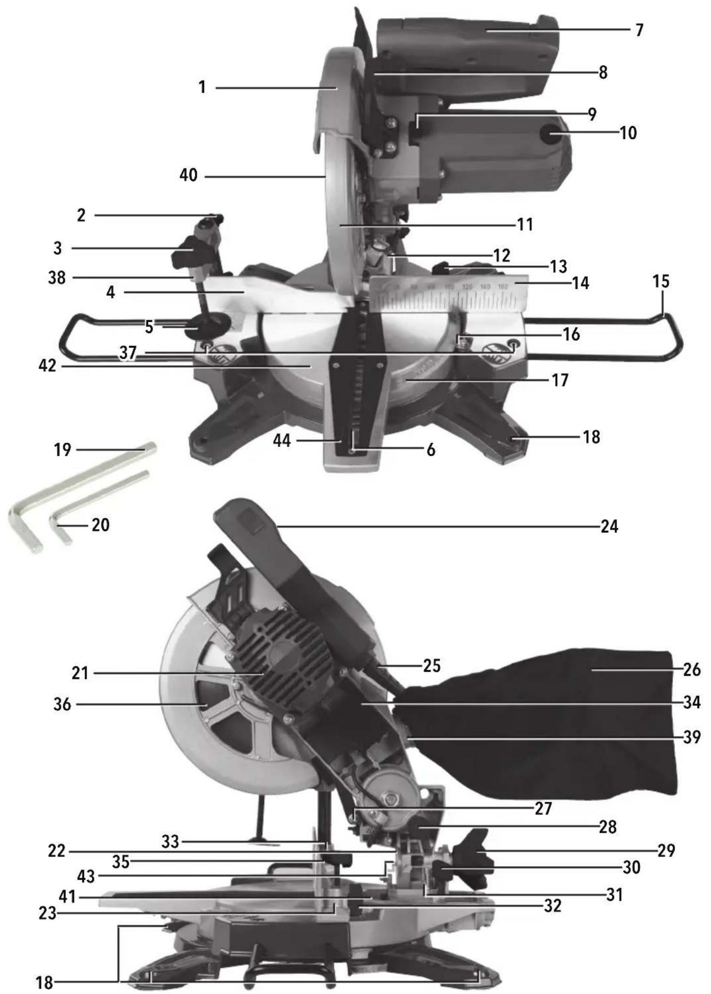
Product Familiarisation
- Blade Guard
- Workpiece Clamp Adjustment Locking Knob
- Workpiece Clamping Screw
- Sliding Fence
- Workpiece Clamping Plate
- Blade Channel
- Operating Handle
- Blade Guard Safety Latch
- Spindle Lock Button
- Brush Access Cover
| 11. | Lower Blade Guard |
| 12. | Slide Rails Mechanism |
| 13. | Mitre Lock |
| 14. | Fixed Fence |
| 15. | Workpiece Supports |
| 16. | Mitre Angle Indicator |
| 17. | Mitre Angle Gauge |
| 18. | Bench Mounting Holes |
| 19. | 5mm Hex Key |
| 20. | 4mm Hex Key |
| 21. | Motor Vents |
| 22. | Bevel Angle Gauge |
| 23. | Workpiece Clamp Slot |
| 24. | ON/OFF Trigger Switch |
| 25. | Power Cord |
| 26. | Dust Collection Bag |
| 27. | Laser |
| 28. | Cutting Head Latching Pin |
| 29. | Bevel Locking Knob |
| 30. | Slide Rails Locking Knob |
| 31. | Bevel Stop/Calibration Screw |
| 32. | Workpiece Clamp Locking Knob |
| 33. | Sliding Fence Screw |
| 34. | Laser ON/OFF Switch |
| 35. | Fence Alignment Screw |
| 36. | Blade |
| 37. | Workpiece Support Screws |
| 38. | Workpiece Clamp |
| 39. | Dust Extraction Port |
| 40. | Arbor Bolt |
| 41. | Slide Rails |
| 42. | Mitre Table |
| 43. | Bevel Angle Indicator |
| 44. | Throat Plate |
Intended Use
Mains powered bench-mounted or portable sliding mitre saw for cutting through wood and other materials. Performs straight and bevel cuts. The included saw blade is suitable for natural wood and artificial composite wood materials.
Note: For non-commercial use only.
Unpacking Your Tool
- Carefully unpack and inspect your product. Fully familiarise yourself with all its features and functions
- Ensure all parts of the product are present and in good condition. If any parts are missing or damaged, have such parts replaced before attempting to use this product
Before Use
WARNING: Important safety devices! Ensure correct function, maintain in accordance with instructions and DO NOT disable!
WARNING: Ensure the tool is disconnected from the power supply before attaching or changing accessories, or making any adjustments.
Note: Cutter/cutting head is a description of the section of the tool incorporating the motor, blade assembly and pivoting arm. On a sliding mitre saw it is the section that traverses the pole arm or arms.
Bench mounting
IMPORTANT: It is recommended to mount the saw to a bench or board. Although the saw can be used without mounting to a bench or board, there is a greater risk to safety during use.
- Mount the saw to a level, horizontal bench or work table using bolts, washers and locking nuts (not supplied) through the four Bench Mounting Holes (18)
- DO NOT over-tighten; this may damage the base
- Do not use bolts that are not a good fit for the Bench Mounting Holes; this may encourage unwanted movement
- Alternatively, mount the saw on 13mm or thicker board, and clamp the board to a work support (Fig. I); this makes it easy to relocate the saw, clamping it to a work support wherever needed
- When using a board it may be necessary to countersink the washers and nuts so the board is level on the surface
WARNING: Ensure the mounting surface is not warped; an uneven surface can cause binding and inaccurate sawing.
Unlatching & raising the Cutting Head
WARNING: ALWAYS ensure the tool is unplugged from the power socket and the blade has come to a complete stop before latching the cutting head down, carrying the tool, and/or unlatching the cutting head.
To unlatch & raise the Cutting Head:
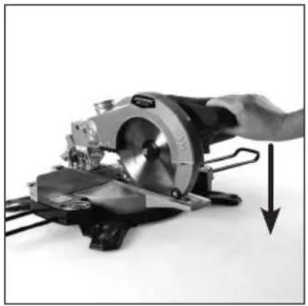
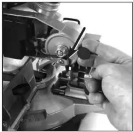
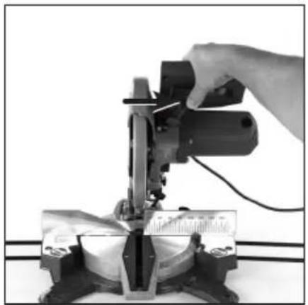
- Press down on the Operating Handle (7) (Image A) and pull out the Cutting Head Latching Pin (28) (Image B)
- Slowly raise the saw's cutting head (Image C)
To lower & latch the Cutting Head:
- From the raised position, disengage the Blade Guard Safety Latch (8) (Image D)
- Press the Operating Handle (7) and cutting head down slowly (Image A) then press in the Cutting Head Latching Pin (28)
Adjusting the Fence
- Ensure the Fence (4 & 14) is used with every cut
- The Sliding Fence (4) can be adjusted and extended out or removed entirely
- To adjust the Sliding Fence loosen the Sliding Fence Screw (33) using the 4mm Hex Key (20) and slide the Fence to the required position (Image E)
- Tighten the Sliding Fence Screw using the 4mm Hex Key to secure the Sliding Fence
Note: If the Workpiece Clamp is attached to the saw on the Sliding Fence it will require removing before Fence adjustment can take place.
- If performing a bevel cut, the Sliding Fence may need to be removed so it does not obstruct the movement of the cutting head or interfere with the Blade (36) when tilted
WARNING: NEVER use the mitre saw without the Fixed Fence.
Adjusting the Workpiece Supports
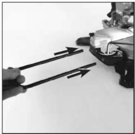
- Loosen the Workpiece Support Screws (37) using the 4mm Hex Key (20)
- Slide the Workpiece Supports (15) into the holes on the side of the tool (Image F)
- Tighten the Workpiece Support Screws to secure the Workpiece Supports in position
Fitting the Workpiece Clamp
- Decide which side of the cutting head that the workpiece is to be clamped (normally the longer side of the workpiece protruding from the tool)
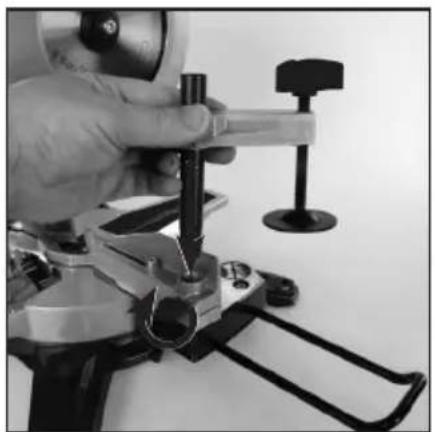
- Insert the Workpiece Clamp (38) fully into the desired Workpiece Clamp Slot (23) (Image G)
- Tighten the Workpiece Clamp Locking Knob (32)
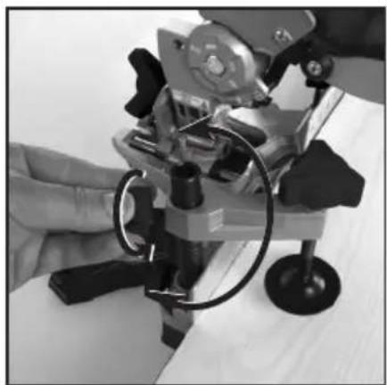
- Position the Clamp over the workpiece by swivelling the upper part of the Clamp and raise or lower the Clamp according to the size of the workpiece (Image H)
- Once the clamp is in position tighten the Workpiece Clamp Adjustment Locking Knob (2)
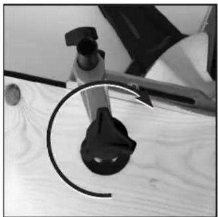
- Screw the Workpiece Clamping Screw (3) clockwise to lower the Workpiece Clamping Plate (5) onto the workpiece to clamp in position (Image I)
Dust Extraction
- Optimal dust extraction is achieved by connecting a dust extraction system or vacuum cleaner to the Dust Extraction Port (39). A dust port adaptor (not supplied) may be required to help connect the dust extraction system to the Dust Port
- The Dust Collection Bag (26) fits directly on to the Dust Extraction Port using a spring clip
- For efficient Dust Bag operation, empty the bag when it is no more than half full, which allows better air flow through the Dust Bag
Transportation
- When transporting or storing the saw, ensure the cutting head is latched down with the Cutting Head Latching Pin (28) and all bevel and mitre locks are in place
- DO NOT carry the saw holding movable parts as this may cause injury
- If the saw is mounted to a bench or support, ensure the fixings are removed and the saw is free to move
- If the saw is mounted to a portable board, ensure the board is unclamped from the workbench or support so the saw is free to move
- When moving or transporting the saw, always keep it upright
Fitting & removing the Blade
WARNING: Never fit and use a blade that is visibly damaged, deformed or has dull or missing teeth.
WARNING: ALWAYS ensure the tool is disconnected from mains power when removing and replacing blades or accessories on the saw.
WARNING: Wear gloves when handling blades.
WARNING: Never attempt to use a blade larger than the stated capacity of the saw, as it might come into contact with the blade guards. Never use a blade that is too thick to allow the outer blade washer to engage with the flats on the spindle; this will prevent the blade screw from properly securing the blade on the spindle.
WARNING: Do not use the saw to cut metal or masonry unless the saw blade is specifically designed for that material and any dust or swarf can be correctly and safely removed in use.
WARNING: Ensure any spacers and spindle rings that may be required are provided by the manufacturer of the blade or confirmed as compatible.
WARNING: Never fit and use a blade made from High Speed Steel (HSS).
IMPORTANT: Even if the blade is pre-fitted, if this is the first use of the tool always check the blade is securely fitted before use.
Note: Cutter/cutting head is a description of the section of the tool incorporating the motor, blade assembly and pivoting arm. On a sliding mitre saw it is the section that traverses the pole arm or arms.
To remove a blade:
- Set the cutting head to the raised position (see 'Unlatching & raising the cutting head' section of this manual).
- Unscrew the Blade Guard (1) spring mechanism nut and screw (Image J)
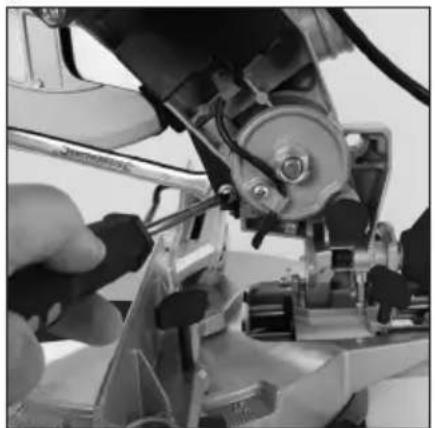
- Press the Blade Guard Safety Latch (8) and retract the Blade Guard (Image K)
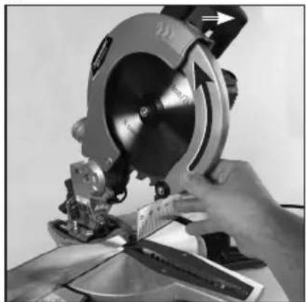
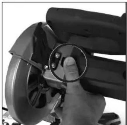
- Press and hold the Spindle Lock Button (9) (Image L)
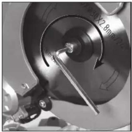
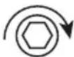
- With Spindle Lock pressed use the 6m (19) to remove the Arbor Bolt (40) by turning the bolt clockwise (Image M):
- Once the Arbor Bolt has been removed, carefully remove the spacers and the Blade (36) from the cutter head
Replacing a blade:
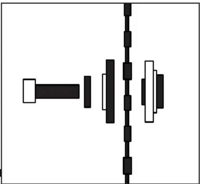
- After removing the existing Blade (36) (see steps 1–6 in 'To remove a blade' section of manual) insert the Blade into the cutter head using any necessary spacers (Fig. II)
Note: Ensure the Blade is installed in the correct rotational directional. - Press and hold the Spindle Lock Button (9)
- Using the 6mm Hex Key (19) tighten the Arbor Bolt (40) by rotating the Bolt anticlockwise:
- Release the Spindle Lock Button; ensure the Blade rotates freely and straight without wobbling or sideways movement
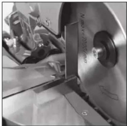
- Check the Blade is 90° to the Mitre Table using a square (Image N)
- Replace the Blade Guard mechanism screw and ensure the guard operates correctly before use
Note: After installing a Blade, always run the saw for a short time before use, to ensure the blade is rotating and operating correctly. If there are any problems, immediately stop the saw, disconnect from the mains power, and amend the problem.

Adjusting the mitre angle
The Mitre Lock (13) is used to lock the Mitre Table (42) at the desired mitre angle. The mitre saw cuts from 0^ to 45^ both left and right.
WARNING: ALWAYS ensure the saw is disconnected from mains power before making any adjustments to angles or bevels.
To adjust the mitre angle:
- If locked, unscrew the Mitre Lock (13) anticlockwise
- With the Mitre Lock released, rotate the Mitre Table (42) to the required mitre angle indicated on the Mitre Angle Gauge (17) via the Mitre Angle Indicator (16) (Image O)
- Once positioned to the correct angle, tighten the Mitre Lock
WARNING: BEFORE MAKING ANY CUTS, ensure the Mitre Lock is always applied. Failure to do so could result in the Mitre Table (42) moving during the cut and could cause serious personal injury.
Adjusting the bevel angle
The saw blade can be set at a desired bevel angle to the left from 0° to 45°.
WARNING: ALWAYS ensure the saw is disconnected from mains power before making any adjustments to angles, bevels, or plunge depths.
To adjust the bevel angle:
- Ensure the Mitre Lock is locked
- Turn the Bevel Locking Knob (29) anticlockwise to release the bevel lock
- Adjust the bevel angle of the cutter to the required angle using the Bevel Angle Gauge (22) for reference (Image P)
- When the required bevel angle is selected tighten the Bevel Locking Knob by rotating clockwise
WARNING: BEFORE MAKING ANY CUTS, ensure the Bevel Locking Knob is tight (29). Failure to do so could result in the saw arm moving during the cut and could cause serious personal injury.
WARNING: ALWAYS ensure that the Sliding Fence (4) does not interfere with the Blades cutting trajectory before making any cuts (see 'Adjusting the Fence' section in this manual.
Releasing & locking the slide rail locking knob
- The saw has a dual slide rail for adjusting the saw forwards and backwards across the cutting table.
- To allow sliding movement slacken the Slide Rails Locking Knob (30) (Image O)
- To lock the cutting head at a particular length tighten the Slide Rails Locking Knob at the required location
Operation
WARNING: ALWAYS wear eye protection, adequate respiratory and hearing protection, and suitable non-woven gloves when working with this tool.
IMPORTANT: Always inspect the mitre saw before each use. Before connecting the saw to mains power, inspect the guards and the correct functioning safety features of the tool.
IMPORTANT: Ensure the operator has adequate training in the operation, adjustment, and maintenance of the mitre saw before connecting the saw to mains power and operating the saw.
WARNING: ALWAYS ensure the tool is unplugged from mains power before adjusting or changing any of the tool's parts. Observe the rotational direction of the blade and compare to the correct rotational direction on the saw blade; at the front of the saw, the blade teeth should always point down.
Switching ON & OFF
- To switch the saw 'ON' squeeze the ON/OFF Trigger Switch (24).
- To switch the saw 'OFF' release the ON/OFF Trigger Switch.
Laser
WARNING: DO NOT look directly into the Laser as this can damage your eyes and potentially cause blindness.
• The Laser operates independently of the saw
• To switch the Laser (27) 'ON' press 'I' on the Laser ON/OFF Switch (34)
- To switch the Laser 'OFF' press '0' on the Laser ON/OFF Switch
Making a cut
WARNING: Never place hands closer than 150mm to the blade. Always keep hands and limbs well clear from the path of the Blade (36) and the Blade Channel (6) (Fig III).
WARNING: Avoid hand positions and awkward usage operations where an accidental slip could cause a hand or fingers to move into the Blade.
IMPORTANT: For accurate cutting, ensure the blade, the fence, the mitre, and the bevels are all calibrated correctly (see 'Calibration' in Maintenance).
Compound mitre cuts:
- A compound mitre cut involves using a mitre angle and a bevel angle at the same time. It is used to make picture frames, cut mouldings, make boxes and sloping sides, and for roof framing
• Always make a test cut on a piece of scrap wood before cutting the workpiece - If making a compound mitre cut, set the required bevel angle (see 'Adjusting the bevel angle') and mitre angle (see 'Adjusting the mitre angle') first, then proceed to cutting
Chop cuts:
• These cuts are used for cutting small or narrow pieces/sections of material
• The cutting head is gently pushed down to cut through the secured workpiece
- The Slide Rails Mechanism (12) should be locked in place at the rearmost position on the Slide Rails (41)
Slide cuts:
- The saw's Slide Rail (41) system allows the saw to make slide cuts
- To completely free up the cutting head, allowing it to glide smoothly, loosen the Slide Rail Locking Knob (30)
- During the cut, the Blade (36) is lowered into the workpiece then pushed back to the rear of the Blade Channel (6) to complete the cut
- Use slide cuts for cutting wider pieces of material (see 'Specifications' for maximum workpiece sizes)
Making a cut:
- With the saw disconnected from the mains power, ensure the required settings—such as mitre angle and bevel angle—are set and locked on the saw
- Place the workpiece flat on the Mitre Table (42) with one edge securely against the Fence (14 & 4)
Note:
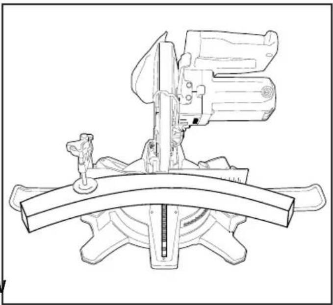
- If the board is warped, place the convex side against the Fence (Fig. IV)
- If the concave side is placed against the Fence, the board could break and jam the Blade
- Use the Workpiece Clamp (38) (see 'Fitting the Workpiece Clamp') on either side of the cutting head where necessary to secure the workpiece
- Use the Workpiece Supports (15) (see 'Adjusting the workpiece supports') if necessary to help stabilise longer workpieces
- Perform a dry run with the cutting head on the workpiece, ensuring the cutting head is free to move up and down, and free to glide smoothly on the Slide Rails (41)
- Connect the saw to mains power
- Hold the Operating Handle (7) firmly and squeeze the ON/OFF Trigger Switch (24)
- Allow the Blade (36) to reach maximum speed, then press the Blade Guard Safety Latch (8) and slowly lower the Blade into and through the workpiece, allowing the speed of the Blade to do all the work (there should be no need to apply undue pressure on the Handle)
- When the cut is completed, release the ON/OFF Trigger Switch then allow the Blade to stop completely before raising the cutting head
- Remove the workpiece only when the Blade is completely stopped and the Blade Guard (1) has completely retracted to cover all of the Blade's teeth
Accessories
- A full range of accessories including saw blades, additional clamps and personal protective equipment is available from your Silverline stockist
- Spare parts can be obtained from toolsparesonline.com
Maintenance
WARNING: ALWAYS ensure the tool is unplugged from mains power before adjusting, changing or calibrating any of the tool's parts, or performing any maintenance or cleaning the tool.
Bevel angle adjustment
Checking 0° angle
- Ensure the cutting head is down and locked with the Cutting Head Latching Pin (28) so that the Blade (36) is in the Blade Channel (6)
- Set the bevel angle to 0^ (see 'Adjusting the bevel angle')
- Raise the cutter head by releasing the latching pin, then check that the bevel is still set to 0^
- Place a set square on the table with one short edge against the Mitre Table (42) and the other short edge against the Blade (avoiding the saw teeth)
Note: If the Blade is not square (90°) with the Mitre Table, adjustment and calibration is required.
Changing 0° angle
- Loosen the Bevel Locking Knob (29) and set the bevel angle to 0^
- Check the 0^ angle by using a square against the surface of the Blade (36) and the Mitre Table (42)
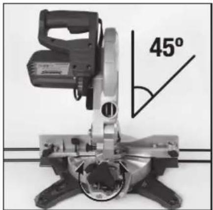
- Set the bevel angle to 45^
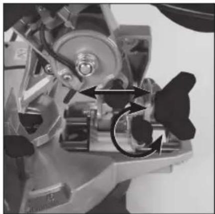
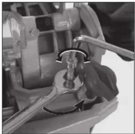
- Loosen the Bevel Stop/Calibration Screw (31) locking nut (Image R)
- Raise or lower the Screw by rotating clockwise/anticlockwise using the 4mm Hex Key (20) (Image R)
- Recheck the 0^ angle using a square
- Once 0^6 angle is achieved, tighten the Bevel Stop/Calibration Screw nut to secure the Screw in place
Checking 45° angle
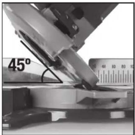
- After calibrating the bevel gauge to true 0^ , set the bevel angle to 45^ and check the Bevel Angle Indicator (43) matches the Bevel Angle Gauge (22)
- Use an appropriate tool to measure and check the 45^ bevel angle of the Blade (36) (Image S)
- If the tool is out and not true 45^ , consult a qualified Silverline service technician
Mitre angle 90° adjustment
The major adjustment of the mitre angle 0^ position is achieved by altering the Fixed Fence (14) position.
- Set the mitre angle to 0^ (See ‘Adjusting the mitre angle’) according to the Mitre Gauge (17) and the Mitre Angle Indicator (16)
- Remove the Sliding Fence (4)
- Lower the cutting head and lock in place with the Cutting Head Latching Pin (28) so that the Blade (36) is in the Blade Channel (6)
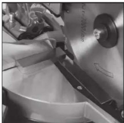
- Use a set square to check the 90^ angle between the Fixed Fence (14) and the Blade (Image T)
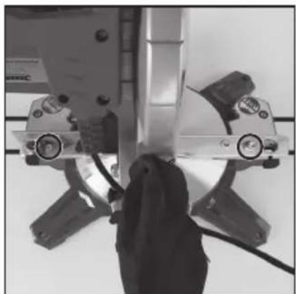
- If the Fence is not square with the Blade, loosen the Fence Alignment Screws (35) and make minor adjustments until the Fixed Fence is 90^ square on both sides of the Blade (Image U)
- Retighten the Fence Alignment Screws
- Release the Cutting Head Latching Pin and allow the cutter head to return to the raised position
Replacing the throat plate
IMPORTANT: If the Throat Plate (44) is damaged or heavily worn, it must be replaced to ensure safe operation of the tool.
- Remove the Fence (14) and Sliding Fence (4) from the Mitre Table (42)
- Set the cutter head bevel to 45°
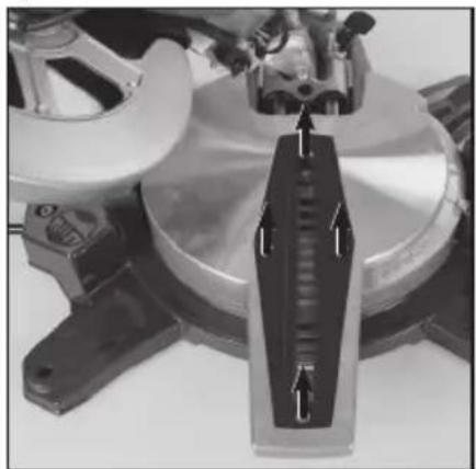
- Unscrew the Throat Plate (44) screws and remove the Throat Plate (Image V)
- Clean the Blade Channel (6) and fit the new Throat Plate
- Retighten Throat Plate screws
- Refit the Fence ensuring it is 90° square with the Blade (36) (see 'Mitre angle 90° adjustment')
General inspection
• Regularly check that all the fixing screws and bolts are tight
- Inspect the tool's Power Cord (25) prior to each use, for damage or wear. Repairs should be carried out by an authorised Silverline service centre. This advice also applies to extension cords used with this tool
Cleaning
- Keep your tool clean at all times. Dirt and dust will cause internal parts to wear quickly, and shorten the machine's service life. Clean the body of your machine with a soft brush or dry cloth. If available, use clean, dry, compressed air to blow through the ventilation holes
- Clean the tool casing with a soft damp cloth using a mild detergent. Do not use alcohol, petrol or strong cleaning agents
- Never use caustic agents to clean plastic parts
- Lubrication
- Slightly lubricate all moving parts at regular intervals with a suitable spray lubricant
- Brushes
• Over time the carbon brushes inside the motor may become worn - Excessively worn brushes may cause loss of power, intermittent failure, or visible sparking
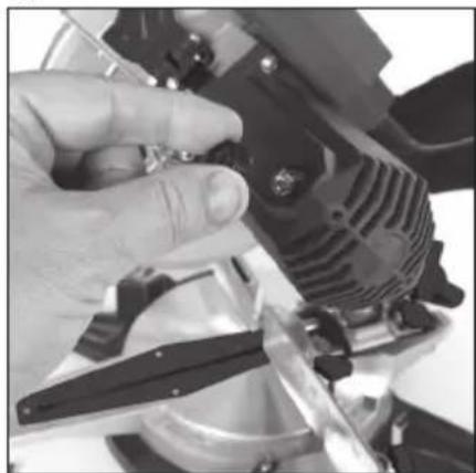
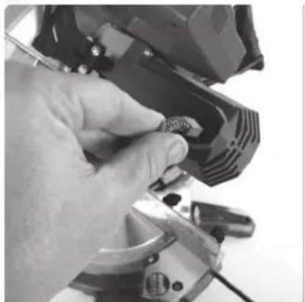
- To replace the brushes, remove the Brush Access Covers (10) from both sides of the motor (Image W). Remove the worn brushes and replace with new (Image X), then replace the covers
• Alternatively, have the tool serviced at an authorised Silverline service centre
Note: Always replace carbon brushes in pairs.
Contact
For technical or repair service advice, please contact the helpline on (+44) 1935 382 222
Web: silverlinetools.com/en-GB/Support
Address:
Powerbox
Boundary Way
Lufton Trading Estate
Yeovil, Somerset
BA22 8HZ, United Kingdom
Storage
- The cutting head can be lowered and secured by the Cutting Head Latching Pin (28) to make the saw a smaller, more secure size for storage
- Ensure all bevel and mitre locks are in place before storing
- Store this tool carefully if a secure, dry place out of the reach of children
Disposal
Always adhere to national regulations when disposing of power tools that are no longer functional and are not viable for repair.
- Do not dispose of power tools, or other waste electronic equipment (WEEE), with household waste
- Contact your local waste disposal authority for information on the correct way to dispose of power tools
Troubleshooting
| Problem Possible cause Solution | ||
| No operation | Plug fuse Replace fuse | |
| Worn brushes | Replace brushes (pair) with new, or have brushes replaced by an authorised Silverline service centre | |
| Power tool fault Contact an authorised Silverline service centre | ||
| Cutting performance poor | Teeth worn or damaged Replace saw Blade (36) | |
| Incorrect saw blade type Replace saw blade with correct type for material being sawed | ||
| Incorrect saw blade specification Ensure saw blade meets the required blade specification for this mitre saw | ||
| Incorrectly fitted saw blade Remove saw blade and refit exactly as per the instructions in this manual | ||
| Power tool vibrating excessively in use | Sawblade distorted, bent or damaged Replace saw blade immediately | |
| Saw blade incorrectly mounted Re fit saw blade exactly as per the instructions in this manual | ||
| Power tool fault Contact an authorised Silverline service centre | ||
| Mitre or bevel angle difficult to adjust | Build-up of saw dust Vacuum up sawdust | |
Silverline Tools Guarantee
This Silverline product comes with a 3 year guarantee
Register this product at www.silverlinetools.com within 30 days of purchase in order to qualify for the 3 year guarantee. Guarantee period begins according to the date of purchase on your sales receipt.
Registering your purchase
Registration is made at silverlinetools.com by selecting the Guarantee Registration button. You will need to enter:-
- Your personal details
• Details of the product and purchase information
Once this information is entered your guarantee certificate will be created in PDF format for you to print out and keep with your purchase.
Terms & Conditions
Guarantee period becomes effective from the date of retail purchase as detailed on your sales receipt.
PLEASE KEEP YOUR SALES RECEIPT
If this product develops a fault within 30 days of purchase, return it to the stockist where it was purchased, with your receipt, stating details of the fault. You will receive a replacement or refund.
If this product develops a fault after the 30 day period, return it to:
Silverline Tools Service Centre
PO Box 2988
Yeovil
BA21 1WU, UK
The guarantee claim must be submitted during the guarantee period.
You must provide the original sales receipt indicating the purchase date, your name, address and place of purchase before any work can be carried out.
You must provide precise details of the fault requiring correction.
Claims made within the guarantee period will be verified by Silverline Tools to establish if the deficiencies are related to material or manufacturing of the product.
Carriage will not be refunded. Items for return must be in a suitably clean and safe state for repair, and should be packaged carefully to prevent damage or injury during transportation. We may reject unsuitable or unsafe deliveries.
All work will be carried out by Silverline Tools or its authorized repair agents.
The repair or replacement of the product will not extend the period of guarantee
Defects recognised by us as being covered by the guarantee shall be corrected by means of repair of the tool, free of charge (excluding carriage charges) or by replacement with a tool in perfect working order.
Retained tools, or parts, for which a replacement has been issued, will become the property of Silverline Tools.
The repair or replacement of your product under guarantee provides benefits which are additional to and do not affect your statutory rights as a consumer.
What is covered:
The repair of the product, if it can be verified to the satisfaction of Silverline Tools that the deficiencies were due to faulty materials or workmanship within the guarantee period.
If any part is no longer available or out of manufacture, Silverline Tools will replace it with a functional replacement part.
Use of this product in the EU.
What is not covered:
Silverline Tools does not guarantee repairs required as a result of:
Normal wear and tear caused by use in accordance with the operating instructions eg blades, brushes, belts, bulbs, batteries etc.
The replacement of any provided accessories drill bits, blades, sanding sheets, cutting discs and other related items.
Accidental damage, faults caused by negligent use or care, misuse, neglect, careless operation or handling of the product.
Use of the product for anything other than normal domestic purposes.
Change or modification of the product in any way.
Use of parts and accessories which are not genuine Silverline Tools components.
Faulty installation (except installed by Silverline Tools).
Repairs or alterations carried out by parties other than Silverline Tools or its authorized repair agents.
Claims other than the right to correction of faults on the tool named in these guarantee conditions are not covered by the guarantee.
CE Declaration of Conformity
The undersigned: Mr Darrell Morris
as authorised by: Silverline Tools
Declares that
This declaration has been issued under the sole responsibility of the manufacturer.
The object of the declaration is in conformity with the relevant Union harmonisation Legislation.
Identification code: 546534
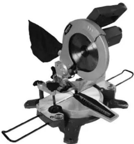
Description: DIY 1450W Sliding Mitre Saw
Conforms to the following directives and standards:
• Machinery Directive 2006/42/EC
• EMC Directive 2014/30/EU
• RoHS Directive 2011/65/EU
• EN 61029-1:2009+A11
• EN 61029-2-9:2012+A11
• EN 55014-1:2006+A1+A2
• EN 55014-2:2015
• EN 61000-3-2:2014
• EN 61000-3-3:2013
Notified body: Rheinland
The technical documentation is kept by: Silverline Tools
Date: 28/09/2018
Signed:
Mr Darrell Morris
Managing Director
Name and address of the manufacturer:
Powerbox International Limited, Company No. 06897059. Registered address:
Powerbox, Boundary Way, Lufton Trading Estate, Yeovil, Somerset BA22 8HZ, United Kingdom.
Introduction
Silverline Tools Service Centre
PO Box 2988
Yeovil
Silverline Tools Service Centre
PO Box 2988
Yeovil
BA21 1WU, GB
WAARSCHUWING: VERMIJD DIRECT OOGCONTACT.
Silverline Tools Service Centre
PO Box 2988
Yeovil
BA21 1WU, GB
Silverline Tools Service Centre
PO Box 2988
Yeovil
BA21 1WU, UK
Powerbox International Limited, Company No. 06897059. Registered address: Powerbox, Boundary
Way, Lufton Trading Estate, Yeovil, Somerset BA22 8HZ, United Kingdom.
natural_image
Mechanical cutting cutter with blade and blade assembly (no visible text or symbols)GB 3 Year Guarantee. Register online within 30 days. Terms and Conditions apply.