285873 - Saw SILVERLINE - Free user manual and instructions
Find the device manual for free 285873 SILVERLINE in PDF.


User questions about 285873 SILVERLINE
0 question about this device. Answer the ones you know or ask your own.
Ask a new question about this device
Download the instructions for your Saw in PDF format for free! Find your manual 285873 - SILVERLINE and take your electronic device back in hand. On this page are published all the documents necessary for the use of your device. 285873 by SILVERLINE.
USER MANUAL 285873 SILVERLINE
JSILVERLINEC® Sow with Laser Guide
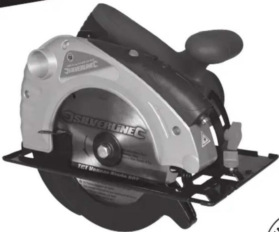
1400W Circular Saw with Laser Guide 185mm
natural_image
Exterior view of a silver cutting tool (no signage or text on the device itself)
text_image
YEAR GUARANTEE 3 REGISTER ONLINE*GB 1400W Circular Saw with Laser Guide
FR Scie circulaire 1 400 W avec guide laser
DE Handkreissäge mit Laserführung, 1400 W
ES Sierra circular con guía láser, 1400 W
IT 1400 W Sega Circolare con Guida Laser
NL 1400 W Silverstorm cirkelzaag met lasergeleider
text_image
A 3.5 x 20 x 2.5 x 24 FOR WOOD TX185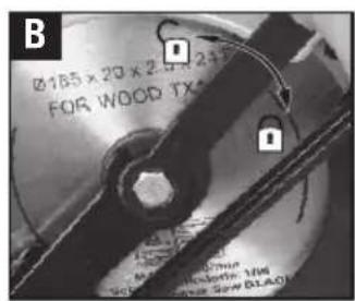
text_image
B Ø185 x 20 x 2.5 x 2+1 FOR WOOD TX Ø185 MILK 20mm SOLVER: 30mm SOLVER: 30mm SLA01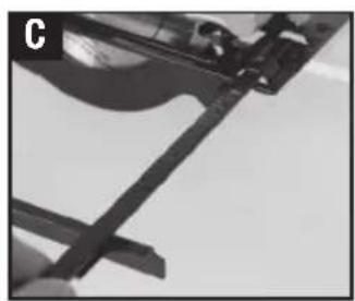
natural_image
Close-up of a mechanical component with a curved blade and attached bracket (no visible text or symbols)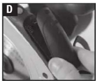
natural_image
Close-up of hands holding a black pen, partially visible with no text or symbols (no legible signage)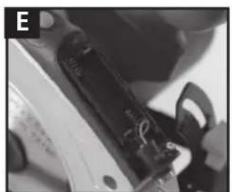
natural_image
Close-up of a mechanical component with a black cylindrical part and a white handle, no visible text or symbols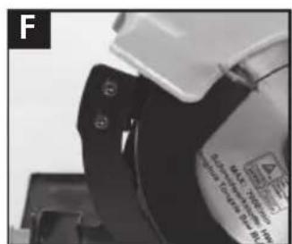
natural_image
Close-up of a mechanical component with mounting holes and a label (no readable text or symbols)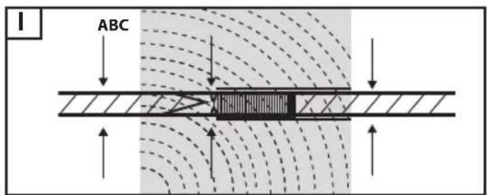
text_image
ABCJSILVERLINEC® Sow with Laser Guide
1400W Circular Saw with Laser Guide 185mm
English 4
Français ...... 12
Deutsch 20
Español ...... 28
Italiano 36
Nederlands......44
Description of Symbols
The rating plate on your tool may show symbols. These represent important information about the product or instructions on its use.

Wear hearing protection
Wear eye protection
Wear breathing protection
Wear head protection

Wear hand protection

Read instruction manual

Wear protective shoes

Double insulated for additional protection

Be aware of kickback!

Warning: Sharp blades or teeth!

DO NOT use in rain or damp environments!

Always disconnect from the power supply when adjusting, changing accessories, cleaning, carrying out maintenance and when not in use!

LASER warning!

Dust extraction required or recommended

WARNING: Moving parts can cause crush and cut injuries

Caution!

Important safety devices! Ensure correct function, maintain in accordance with instructions and DO NOT disable!

Class II construction (double insulated for additional protection
Environmental Protection
Waste electrical products should not be disposed of with household waste. Please recycle where facilities exist. Check with your local authority or retailer for recycling advice

Conforms to relevant legislation and safety standards
Technical Abbreviations Key
| V Volts | |
| ~ Alternating current | |
| A Ampere | |
| no No load speed | |
| Hz Hertz | |
| W, kW Watt, kilowatt | |
| /min or min ^-1 | (revolutions or reciprocation) per minute |
Specification
Voltage: 230-240V\~50Hz
Power: 1400W
Laser power:....2 x AAA batteries
Laser Type: Class 2, λ650nm
No load speed: 4500min ^1
Blade size (max): 0185mm
Bore: 020mm
Riving knife thickness: 2mm
Supplied blade:....Ø185 x Ø20 x 2.5 x 1.6mm x 24T
Max depth of cut: 63mm (0°)
40mm (45°)
Bevel Range: 0-45°
Protection Class: ....

Ingress Protection Rating: IP20
Dimensions (L x W x H): 300 x 230 x 250mm
Power cable: 2m
Weight: 3.5kg
As part of our ongoing product development, specifications of Silverline products may alter without notice
Sound and Vibration Information
Sound pressure (L PA): 98dB(A)
Sound power (L _WA ): 109dB(A)
Uncertainty K: 3dB(A)
Weighted vibration a _n :
Main handle: 4.983m/s²
Front handle: 3.439m/s²
Uncertainty K: 1.5m/s²
The sound intensity level for the operator may exceed 85dB(A) and sound protection measures are necessary.
WARNING: Always wear ear protection where the sound level exceeds 85dB(A) and limit the time of exposure if necessary. If sound levels are uncomfortable, even with ear protection, stop using the tool immediately and check the ear protection is correctly fitted and provides the correct level of sound attenuation for the level of sound produced by your tool.
WARNING: User exposure to tool vibration can result in loss of sense of touch, numbness, tingling and reduced ability to grip. Long term exposure can lead to a chronic condition. If necessary, limit the length of time exposed to vibration and use anti-vibration gloves. Do not operate the tool with hands below a normal comfortable temperature, as vibration will have a greater effect. Use the figures provided in the specification relating to vibration to calculate the duration and frequency of operating the tool.
Sound and vibration levels in the specification are determined according to EN60745 or similar international standards. The figures represent normal use for the tool in normal working conditions. A poorly maintained, incorrectly assembled, or misused tool, may produce increased levels of noise and vibration. www.osha.europa.eu provides information on sound and vibration levels in the workplace that may be useful to domestic users who use tools for long periods of time.
General Safety
WARNING Read all safety warnings and all instructions. Failure to follow the warnings and instructions may result in electric shock, fire and/or serious injury.
Save all warnings and instructions for future reference.
The term "power tool" in the warnings refers to your mains-operated (corded) power tool or battery-operated (cordless) power tool.
1) Work area safety
a) Keep work area clean and well lit. Cluttered or dark areas invite accidents
b) Do not operate power tools in explosive atmospheres, such as in the presence of flammable liquids, gases or dust. Power tools create sparks which may ignite the dust or fumes
c) Keep children and bystanders away while operating a power tool. Distractions can cause you to lose control
2) Electrical safety
a) Power tool plugs must match the outlet. Never modify the plug in any way. Do not use any adapter plugs with earthed (grounded) power tools. Unmodified plugs and matching outlets will reduce risk of electric shock
b) Avoid body contact with earthed or grounded surfaces, such as pipes, radiators, ranges and refrigerators. There is an increased risk of electric shock if your body is earthed or grounded
c) Do not expose power tools to rain or wet conditions. Water entering a power tool will increase the risk of electric shock
d) Do not abuse the cord. Never use the cord for carrying, pulling or unplugging the power tool. Keep cord away from heat, oil, sharp edges or moving parts. Damaged or entangled cords increase the risk of electric shock
e) When operating a power tool outdoors, use an extension cord suitable for outdoor use. Use of a cord suitable for outdoor use reduces the risk of electric shock
f) If operating a power tool in a damp location is unavoidable, use a residual current device (RCD) protected supply. Use of an RCD reduces the risk of electric shock
WARNING: When used in Australia or New Zealand, it is recommended that this tool is ALWAYS supplied via Residual Current Device (RCD) with a rated residual current of 30mA or less.
3) Personal safety
a) Stay alert, watch what you are doing and use common sense when operating a power tool. Do not use a power tool while you are tired or under the influence of drugs, alcohol or medication. A moment of inattention while operating power tools may result in serious personal injury
b) Use personal protective equipment. Always wear eye protection. Protective equipment such as dust mask, non-skid safety shoes, hard hat, or hearing protection used for appropriate conditions will reduce personal injuries
c) Prevent unintentional starting. Ensure the switch is in the off-position before connecting to power source and/or battery pack, picking up or carrying the tool. Carrying power tools with your finger on the switch or energising power tools that have the switch on invites accidents
d) Remove any adjusting key or wrench before turning the power tool on. A wrench or a key left attached to a rotating part of the power tool may result in personal injury
e) Do not overreach. Keep proper footing and balance at all times. This enables better control of the power tool in unexpected situations
f) Dress properly. Do not wear loose clothing or jewellery. Keep your hair, clothing and gloves away from moving parts. Loose clothes, jewellery or long hair can be caught in moving parts
g) If devices are provided for the connection of dust extraction and collection facilities, ensure these are connected and properly used. Use of dust collection can reduce dust-related hazards
4) Power tool use & care
a) Do not force the power tool. Use the correct power tool for your application. The correct power tool will do the job better and safer at the rate for which it was designed
b) Do not use the power tool if the switch does not turn it on and off. Any power tool that cannot be controlled with the switch is dangerous and must be repaired
c) Disconnect the plug from the power source and/or the battery pack from the power tool before making any adjustments, changing accessories, or storing power tools. Such preventive safety measures reduce the risk of starting the power tool accidentally
d) Store idle power tools out of the reach of children and do not allow persons unfamiliar with the power tool or these instructions to operate the power tool. Power tools are dangerous in the hands of untrained users
e) Maintain power tools. Check for misalignment or binding of moving parts, breakage of parts and any other condition that may affect the power tool's operation. If damaged, have the power tool repaired before use. Many accidents are caused by poorly maintained power tools
f) Keep cutting tools sharp and clean. Properly maintained cutting tools with sharp cutting edges are less likely to bind and are easier to control
g) Use the power tool, accessories and tool bits etc. in accordance with these instructions, taking into account the working conditions and the work to be performed. Use of the power tool for operations different from those intended could result in a hazardous situation
5) Service
a) Have your power tool serviced by a qualified repair person using only identical replacement parts. This will ensure that the safety of the power tool is maintained.
Circular Saw Safety
Cutting procedures
a) ⚠️ DANGER: Keep hands away from cutting area and the blade. Keep your second hand on auxiliary handle, or motor housing. If both hands are holding the saw, they cannot be cut by the blade.
b) Do not reach underneath the workpiece. The guard cannot protect you from the blade below the workpiece.
c) Adjust the cutting depth to the thickness of the workpiece. Less than a full tooth of the blade teeth should be visible below the workpiece.
d) Never hold piece being cut in your hands or across your leg. Secure the workpiece to a stable platform. It is important to support the work properly to minimise body exposure, blade binding, or loss of control.
e) Hold the power tool by insulated gripping surfaces only, when performing an operation where the cutting tool may contact hidden wiring or its own cord. Contact with a "live" wire will also make exposed metal parts of the power tool "live" and could give the operator an electric shock.
f) When ripping, always use a rip fence or straight edge guide. This improves the accuracy of cut and reduces the chance of blade binding.
g) Always use blades with correct size and shape (diamond versus round) of arbour holes. Blades that do not match the mounting hardware of the saw will run eccentrically, causing loss of control.
h) Never use damaged or incorrect blade washers or bolts. The blade washers and bolt were specially designed for your saw, for optimum performance and safety of operation.
Further Safety Instructions For All Saws
Kickback causes and related warnings
- Kickback is a sudden reaction to a pinched, bound or misaligned saw blade, causing an uncontrolled saw to lift up and out of the workpiece toward the operator;
- When the blade is pinched or bound tightly by the kerf closing down, the blade stalls and the motor reaction drives the unit rapidly back toward the operator;
- If the blade becomes twisted or misaligned in the cut, the teeth at the back edge of the blade can dig into the top surface of the wood causing the blade to climb out of the kerf and jump back toward the operator.
Kickback is the result of saw misuse and/or incorrect operating procedures or conditions and can be avoided by taking proper precautions as given below.
a) Maintain a firm grip with both hands on the saw and position your arms to resist kickback forces. Position your body to either side of the blade, but not in line with the blade. Kickback could cause the saw to jump backwards, but kickback forces can be controlled by the operator if proper precautions are taken.
b) When blade is binding, or when interrupting a cut for any reason, release the trigger and hold the saw motionless in the material until the blade comes to a complete stop. Never attempt to remove the saw from the work or pull the saw backward while the blade is in motion or kickback may occur. Investigate and take corrective actions to eliminate the cause of blade binding.
c) When restarting a saw in the workpiece, centre the saw blade in the kerf and check that saw teeth are not engaged into the material. If saw blade is binding, it may walk up or kickback from the workpiece as the saw is restarted.
d) Support large panels to minimise the risk of blade pinching and kickback. Large panels tend to sag under their own weight.
Supports must be placed under the panel on both sides, near the line of cut and near the edge of the panel.
e) Do not use dull or damaged blades. Unsharpened or improperly set blades produce narrow kerf causing excessive friction, blade binding and kickback.
f) Blade depth and bevel adjusting locking levers must be tight and secure before making cut. If blade adjustment shifts while cutting, it may cause binding and kickback.
g) Use extra caution when sawing into existing walls or other blind areas. The protruding blade may cut objects that can cause kickback.
Lower guard function
a) Check lower guard for proper closing before each use. Do not operate the saw if lower guard does not move freely and close instantly. Never clamp or tie the lower guard into the open position. If saw is accidentally dropped, lower guard may be bent. Raise the lower guard with the retracting handle and make sure it moves freely and does not touch the blade or any other part, in all angles and depths of cut.
b) Check the operation of the lower guard spring. If the guard and the spring are not operating properly, they must be serviced before use. Lower guard may operate sluggishly due to damaged parts, gummy deposits, or a build-up of debris.
c) Lower guard may be retracted manually only for special cuts such as "plunge cuts" and "compound cuts". Raise lower guard by retracting handle and as soon as blade enters the material, the lower guard must be released. For all other sawing, the lower guard should operate automatically.
d) Always observe that the lower guard is covering the blade before placing saw down on bench or floor. An unprotected, coasting blade will cause the saw to walk backwards, cutting whatever is in its path. Be aware of the time it takes for the blade to stop after switch is released.
Riving knife function
a) Use the appropriate saw blade for the riving knife. For the riving knife to function, the body of the blade must be thinner than the riving knife and the cutting width of the blade must be wider than the thickness of the riving knife.
b) Adjust the riving knife as described in this instruction manual. Incorrect spacing, positioning and alignment can make the riving knife ineffective in preventing kickback.
c) Always use the riving knife except when plunge cutting. Riving knife must be replaced after plunge cutting. Riving knife causes interference during plunge cutting and can create kickback.
d) For the riving knife to work, it must be engaged in the workpiece. The riving knife is ineffective in preventing kickback during short cuts.
e) Do not operate the saw if riving knife is bent. Even a light interference can slow the closing rate of a guard.
Additional circular saw safety
WARNING: Before connecting a tool to a power source (mains switch power point receptacle, outlet, etc.) be sure that the voltage supply is the same as that specified on the nameplate of the tool. A power source with a voltage greater than that specified for the tool can result in serious injury to the user, and damage to the tool. If in doubt, do not plug in the tool. Using a power source with a voltage less than the nameplate rating is harmful to the motor.
a) Do not allow anyone under the age of 18 years to operate this saw
b) When operating the saw, use safety equipment including safety goggles or shield, ear protection, dust mask and protective clothing including safety gloves
c) Hand-held power tools may produce vibration. Vibration can cause disease. Gloves may help to maintain blood circulation in the fingers. Hand-held tools should not be used for long periods without a break
d) Whenever possible, use a vacuum dust extraction system to control dust/waste
e) Do not attempt to cut material thicker than detailed in the Specifications section of this manual
f) Adjust the cutting depth to the thickness of the workpiece i.e. less than a full tooth of the blade should be visible below the workpiece
g) Ensure work is correctly supported. Large panels may sag under their own weight and bind the saw blade. Supports must be placed under the panel on both sides, close to the line of cut and near the edge of the panel
h) Ensure all supports and power cables are completely clear of the cutting path
i) Always secure the workpiece to a stable platform, ensuring body exposure is minimised, avoiding blade binding, or loss of control
j) Always stand at an angle to the tool when operating
k) Be aware that the blade will project from the underside of the workpiece
I) Do not reach beneath the workpiece where the guard cannot protect you from the blade
m) Note the direction of rotation of the motor and the blade
n) Inspect the workpiece and remove all nails and other embedded objects prior to starting work
o) Do not apply any sideways or twisting force to the blade whilst cutting
p) If a cut does not extend to the edge of the workpiece, or if the blade binds in the cut, allow the blade to come to a complete stop and lift the saw out of the workpiece
q) Do not attempt to free a jammed blade before first disconnecting the machine from power
r) Do not move the saw backwards at any time whilst cutting
s) Beware of projected waste. In some situations, waste material may be projected at speed from the cutting tool. It is the user's responsibility to ensure other people in the work area are protected from the possibility of projected waste
t) If you are interrupted when operating the saw, complete the process and switch off before diverting your attention
u) Check the lower guard for proper closure before each use. Do not operate the saw if the lower guard does not move freely and close instantly. Never clamp or tie the lower guard into the open position. If the saw is accidentally dropped, the lower guard may be bent. Raise the lower guard with the retracting handle and make sure it moves freely and does not touch the blade or any other part, in all angles and depths of cut
v) Always observe that the lower guard is covering the blade before resting the saw on a surface after use. An unprotected, coasting blade will cause the saw to move backwards, cutting whatever is in its path. Be aware of the time it takes for the blade to stop after the trigger switch is released
w) Periodically check that all nuts, bolts and other fixings have not become loose, and tighten where necessary
The tool must be used only for its prescribed purpose. Any use other than those mentioned in this manual will be considered a case of misuse. The user, and not the manufacturer, shall be liable for any damage or injury resulting from such cases of misuse.
The manufacturer shall not be liable for any modifications made to the tool nor for any damage resulting from such modifications. Even when the tool is used as prescribed it is not possible to eliminate all residual risk factors.
Laser Safety
The laser used in this device is a Class 2 laser with maximum power of ≤ 1mW and a wavelength of 650Nm.
These lasers do not normally present an optical hazard, although staring at the beam may cause flash blindness.
WARNING: Avoid direct eye contact.
A hazard may exist if you deliberately stare into the beam, please observe all safety rules as follows:
- The laser shall be used and maintained in accordance with the manufacturer's instructions
- Do not switch on the laser light until the tool is ready to cut
- Never aim the beam at any person, and particularly not into the eyes of any person or animal, or any object other than the workpiece
- Always ensure the laser beam is aimed at a sturdy workpiece without reflective surfaces. i.e. wood or rough-coated surfaces are acceptable. Reflective sheet steel or similar is not suitable for laser use as the reflective surface could direct the beam back at the operator
- Do not change the laser light assembly. Repairs must only be carried out by the laser manufacturer or an authorised agent. DO NOT exchange with a different type of laser
CAUTION: Use of controls or adjustments or performance of procedures other than those specified herein may result in hazardous radiation exposure.
Please refer to the relevant EN standards, EN60825-1:2007 for more information on Lasers.
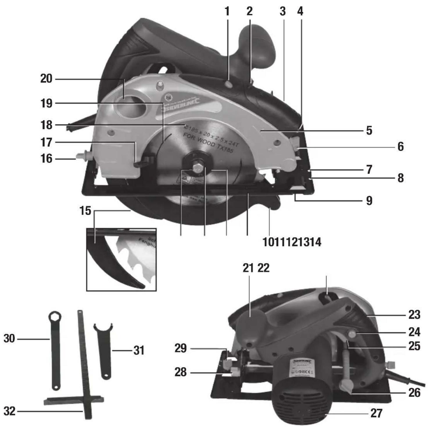
Product Familiarisation
- Laser On/Off Switch
- Battery Compartment Button
- Battery Compartment Cover
- Laser
- Direction Indicator
- Guide Locking Knob
- 45° Line
- 0° Line
- Guide Slot
- Lower Guard
- Base Plate
- Blade Flange
- Blade Washer
- Blade Securing Bolt
- Riving Knife
- Minor Bevel Angle Locking Knob
- Lower Guard Lever
- Blade
- Blade Direction Indicator
- Dust Extraction Port
- Front Handle
- Depth Scale
-
Rear Handle
-
Safety Lock-Off Button
-
On/Off Trigger
-
Depth Locking Knob
-
Motor Vents
-
Bevel Angle Locking Knob
-
Bevel Angle Scale
-
Blade Spanner
-
Pin Spanner
-
Parallel Guide Fence
Fig I
A – Riving knife
B - Kerf (cutting/teeth width)
C - Blade body
Intended Use
Hand-held portable mains circular saw for cross, rip and bevel cutting of hard and soft woods, natural and composite. Suitable for additional materials when an additional compatible blade is fitted. Plunge/pocket cuts can only be performed by a skilled operator once the riving knife is removed.
Unpacking Your Tool
- Carefully unpack and inspect your tool. Familiarise yourself with all its features and functions.
- Ensure that all parts of the tool are present and in good condition. If any parts are missing or damaged, have such parts replaced before attempting to use this tool.
Before Use
Dust extraction
- For a cleaner, safer work environment, and to protect the tool from dust and over-heating, connect a dust extraction system or workshop vacuum cleaner to the Dust Extraction Port (20)
Note: The supplied blade is pre-fitted. Make sure the Blade Securing Bolt (14) is securely tightened before first use
Fitting and removing blades
WARNING: Wear cut-proof gloves when handling sharp blades.
• Always check the blade being fitted is suitable for the material being cut
- Only fit blades that are in perfect condition. Blunt, bent, and cracked blades should be discarded
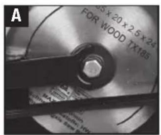
- Fit the Pin Spanner (31) into the recess as shown in Image A and into the two holes of the Blade Flange (12). Unscrew the Blade Securing Bolt (14) anti-clockwise using the supplied Blade Spanner (30)
- Remove the Blade Securing Bolt, Blade Washer (13) and Blade Flange (12)
- Use the Lower Guard Lever (17) to rotate the Lower Guard out of the way and slide the existing blade out
- Fit the required blade, making sure the Blade Direction Indicator (19) on the face of the blade is in the same direction as the Direction Indicator (5)
- Re-fit the Blade Flange, Blade Washer and Blade Securing Bolt.
- Ensure the blade is secure before use
Laser guide – installing batteries
- Press the Battery Compartment Button (2) and slide the Battery Compartment Cover (3) towards the Laser On/Off Switch (1) and remove
- Insert 2 x AAA batteries into the battery compartment (Image D). Ensure the polarity of the batteries is correct when fitting
- Place the Battery Compartment Cover in the position shown in Image E and slide back into place over the batteries, the cover will lock back in place
Setting bevel angle
- This saw is equipped with a tilting Base Plate (11). This allows bevel cuts to be made
- Alter the angle of the Base Plate by loosening the Bevel Angle Locking Knob (28) and the Minor Bevel Angle Locking Knob (16). The Base Plate will now be free to pivot
- Select the angle required (0-45°) using the Bevel Angle Scale (29) and retighten the Bevel Angle Locking Knob and Minor Bevel Angle Locking Knob
- Ensure accuracy by checking the angle between the Blade (18) and the Base Plate using a suitable protractor
Setting depth adjustment
- Alter the depth of the cut by loosening the Depth Locking Knob (26). The Base Plate (11) is now free to adjust to the required depth
- Adjust the Base Plate to the required depth using the Depth Scale (22) or a ruler, and retighten the Depth Locking Knob
- When set correctly, the blade teeth should project approximately 3mm from the underside of the material being cut
Fitting the parallel guide fence
- The Parallel Guide Fence (32) can be used on the left or the right of the Blade (18)
- Using the Parallel Guide Fence provides accurate cuts without the need to follow pencil lines
- Loosen the Guide Locking Knob (6) and insert the Parallel Guide Fence (27) into the required side of the base (Image C)
- Set to the required position for the cut using the graduations on the fence and base
- Tighten the Guide Locking Knob to lock it into position
Operation
Before using the saw, practise on scrap material. The settings of the machine are crucial to achieving a good quality finish, and your work could easily be damaged by using an incorrect setting
Handling your circular saw
• Always hold the saw securely, with both hands, by the handles provided
- Always allow the blade to come to a complete stop before placing the machine down
• Always unplug the machine if it is to be left unattended
- Always make sure that work will not move whilst being cut. Use clamps where appropriate
Making a Cut
- Hold the saw securely and rest the front edge of the Base Plate (5) on the edge of the workpiece
- Check that the blade is not in contact with the workpiece, or any other object
- To start the machine, depress the Lock Off Button (12) and squeeze the Trigger Switch (11)
- Allow the motor to reach full speed
- Smoothly push the saw forward across the workpiece
NOTE: The front edge of the base plate features guide notches. For normal 0^ cutting align the notch 0^ Line (8) with the line to be cut, for 45^ bevel cutting align the notch 45^ Line (7) with the line to be cut.
-
Allow the blade to pass through the material and release the trigger switch. Alternatively, if the cut does not reach the edge of the workpiece, release the trigger switch and allow the blade to stop moving before lifting out of the cut
-
Do not place the machine down until the blade has stopped completely
Using the parallel guide fence
When working parallel to an edge, use the Parallel Guide Fence (6)
-
When working parallel to an edge, the Parallel Guide Fence (32) should be used
-
The position of the guide fence can be adjusted to suit different tasks
-
Follow an edge by keeping the vertical foot of the guide fence pressed against the vertical edge, to be followed as the cut is made
Laser
WARNING: Do not stare directly at the laser beam. Never aim the beam at any person or object other than the workpiece.
- Ensure the laser beam is aimed at a sturdy workpiece without reflective surfaces - wood or rough-coated surfaces are acceptable. Bright shiny reflective sheet steel or the like is not suitable for laser use as the reflective surface could direct the beam back at the operator
-
Only switch the laser beam on when the tool is on the workpiece
-
Rest the front edge of the saw Base Plate (11) on the workpiece. Ensure the blade is not touching the workpiece
-
Switch on the Laser On/Off Switch (1)
Note: If the laser does not operate the batteries may need replacing.
- Line up the laser beam with your pencil line
- Commence the cut
- Switch off the laser beam
Riving knife
- This power tool has a fitted Riving Knife (15) which is a small blade behind the main Blade (18). This is an important safety device which helps to prevent kickback in use
- The thickness of the Riving Knife (A) should be between the kerf (B) and the blade body (C), see Fig. I
- The tool is supplied configured with the correct blade for the Riving Knife. Ensure replacement blades have a blade thickness less than the Riving Knife, but with a kerf (teeth thickness) that exceeds it for correct optimal operation
- In some instances the Riving Knife may need to be removed, re-flattened or replaced. Access the Riving Knife bolts (Image F) by loosening the Depth Locking Knob (26) and setting to the maximum depth position as shown on the Depth Scale (22)
- Replace immediately if it becomes damaged or cannot be made flat
- Position it so it is centralised behind the saw blade. The riving blade bolts may require additional washers to centralise the riving knife when using different thickness saw blades
- Removing the riving knife for plunge/pocket cuts needs special care and attention. Take time to prepare and make sure all safety precautions are followed. Do not attempt to make plunge/pocket cuts with the riving knife fitted. If the riving knife is not easily removed and refitted the saw is not suitable for plunge/pocket cuts
WARNING: Always re-fit the riving knife it is an essential safety feature for normal use.
Accessories
A range of accessories are available for this power tool from your Silverline dealer including saw blades. Spare parts are available from your Triton dealer or www.toolsparesonline.com.
Maintenance
WARNING: Always disconnect from the power supply before carrying out any maintenance/cleaning.
Laser adjustment
Note: The laser is pre-configured at the factory and in normal use does not need adjustment.
If the laser does need adjustment, the assembly may be lightly glued into the correct position. Make an adjustment by removing the two screws of the assembly (Image D) and carefully separating any existing glue with a precision knife to ensure the cables are not damaged. Refit the two screws so they only just maintain the laser in its set position, and make fine adjustments to its position. Once set correctly tighten the screws and carry out a test cut to ensure this position is correct. Due to the high vibration of the tool a small amount of glue can be applied to maintain this set position.
General inspection
- Regularly check that all the fixing screws are tight. They may vibrate loose over time
- Inspect the supply cord of the tool, prior to each use, for damage or wear. Repairs should be carried out by an authorised Silverline service centre. This advice also applies to extension cords used with this tool
Cleaning
WARNING: ALWAYS wear protective equipment including eye protection and gloves when cleaning this tool.
- Keep your tool clean at all times. Dirt and dust will cause internal parts to wear quickly, and shorten the device's service life
- Clean the body of your machine with a soft brush, or dry cloth
- Never use caustic agents to clean plastic parts. If dry cleaning is not sufficient, a mild detergent on a damp cloth is recommended
• Water must never come into contact with the tool - Ensure the tool is thoroughly dry before using it
- If available, use clean, dry, compressed air to blow through the ventilation holes (where applicable)
Brushes
• Over time the carbon brushes inside the motor may become worn
- Excessively worn brushes may cause loss of power, intermittent failure, or visible sparking
1. To replace the brushes, remove the two screws next to the Motor Vents (27) and remove the Motor Vents cover
2. Carefully remove the worn brushes from their housings and replace with new ensuring no part of the motor is scratched or damaged. Always replace both carbon brushes at the same time
3. Refit the cover
- Alternatively, have the machine serviced at an authorised Silverline service centre
- New carbon brushes will take a short while to bed in and give full performance and normal sound levels
Note: Carbon brushes are available from www.toolsparesonline.com.
Storage
- Store this tool carefully in a secure, dry place out of the reach of children
- For long-term storage, remove the laser batteries and store separately
Disposal
- Always adhere to national regulations when disposing of power tools that are no longer functional and are not viable for repair.
- Do not dispose of power tools, or other waste electrical and electronic equipment (WEEE), with household waste
- Contact your local waste disposal authority for information on the correct way to dispose of power tools
- Contact your local waste disposal authority for information on the correct way to dispose of power tools
Silverline Tools Guarantee
This Silverline product comes with a 3 year guarantee
Register this product at www.silverlinetools.com within 30 days of purchase in order to qualify for the 3 year guarantee. Guarantee period begins according to the date of purchase on your sales receipt.
Registering your purchase
Registration is made at silverlinetools.com by selecting the Guarantee Registration button. You will need to enter:-
- Your personal details
• Details of the product and purchase information
Once this information is entered your guarantee certificate will be created in PDF format for you to print out and keep with your purchase.
Terms & Conditions
Guarantee period becomes effective from the date of retail purchase as detailed on your sales receipt.
PLEASE KEEP YOUR SALES RECEIPT
If this product develops a fault within 30 days of purchase, return it to the stockist where it was purchased, with your receipt, stating details of the fault. You will receive a replacement or refund.
If this product develops a fault after the 30 day period, return it to:
Silverline Tools Service Centre
PO Box 2988
Yeovil
BA21 1WU, UK
The guarantee claim must be submitted during the guarantee period.
You must provide the original sales receipt indicating the purchase date, your name, address and place of purchase before any work can be carried out.
You must provide precise details of the fault requiring correction.
Claims made within the guarantee period will be verified by Silverline Tools to establish if the deficiencies are related to material or manufacturing of the product.
Carriage will not be refunded. Items for return must be in a suitably clean and safe state for repair, and should be packaged carefully to prevent damage or injury during transportation. We may reject unsuitable or unsafe deliveries.
All work will be carried out by Silverline Tools or its authorized repair agents.
The repair or replacement of the product will not extend the period of guarantee
Defects recognised by us as being covered by the guarantee shall be corrected by means of repair of the tool, free of charge (excluding carriage charges) or by replacement with a tool in perfect working order.
Retained tools, or parts, for which a replacement has been issued, will become the property of Silverline Tools.
The repair or replacement of your product under guarantee provides benefits which are additional to and do not affect your statutory rights as a consumer.
What is covered:
The repair of the product, if it can be verified to the satisfaction of Silverline Tools that the deficiencies were due to faulty materials or workmanship within the guarantee period.
If any part is no longer available or out of manufacture, Silverline Tools will replace it with a functional replacement part.
Use of this product in the EU.
What is not covered:
Silverline Tools does not guarantee repairs required as a result of:
Normal wear and tear caused by use in accordance with the operating instructions eg blades, brushes, belts, bulbs, batteries etc.
The replacement of any provided accessories drill bits, blades, sanding sheets, cutting discs and other related items.
Accidental damage, faults caused by negligent use or care, misuse, neglect, careless operation or handling of the product.
Use of the product for anything other than normal domestic purposes.
Change or modification of the product in any way.
Use of parts and accessories which are not genuine Silverline Tools components.
Faulty installation (except installed by Silverline Tools).
Repairs or alterations carried out by parties other than Silverline Tools or its authorized repair agents.
Claims other than the right to correction of faults on the tool named in these guarantee conditions are not covered by the guarantee.
Battery Guarantee
Silverline batteries are guaranteed for 30 days. If a defect occurs on a registered battery during the term of the Battery Guarantee, due to material or manufacturing fault, then Silverline will replace it free of charge. This guarantee does not apply to commercial use nor does it extend to normal wear and tear or damage as a result of accident, abuse or misuse.
CE Declaration of Conformity
The undersigned: Mr Darrell Morris
as authorised by: Silverline Tools
Declares that
Identification code: 285873
Description: 1400W Circular Saw with Laser Guide
Conforms to the following directives and standards:
• Machinery Directive 2006/42/EC
• Low Voltage Directive 2006/95/EC
• EMC Directive 2004/108/EC
• RoHS Directive 2011/65/EU
• EN60745-1:2009+A11:2010
• EN60745-2-2:2010
• EN55014-1:2006+A1:2009+A2:2011
• EN55014-2:1997+A1:2001+A2:2008
• EN61000-3-2:2006+A1:2009+A2:2009
• EN61000-3-3:2008
Notified body: TÜV Rheinland
The technical documentation is kept by: Silverline Tools
Date: 24/02/2015
Signed:
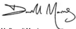
Mr Darrell Morris
Managing Director
Name and address of the manufacturer:
Powerbox International Limited, Company No. 06897059. Registered address: Central House, Church Street, Yeovil, Somerset BA20 1HH, United Kingdom.
Silverline Tools Service Centre
PO Box 2988
Yeovil
TolleranzaK: 3dB (A)
WAARSCHUWING: Voorkom direct oogcontact
Silverline Tools Service Centre
PO Box 2988
Yeovil
BA21 1WU, GB
natural_image
Exterior view of a silver and black circular saw cutting a circular blade (no text or symbols visible on the saw itself)
3 Year Guarantee
*Register online within 30 days. Terms & Conditions apply