
PV 5300 - Mixer PEAVEY - Free user manual and instructions
Find the device manual for free PV 5300 PEAVEY in PDF.
| Product type | All-in-one powered mixer |
| Brand | Peavey |
| Model | PV 5300 |
| Dimensions (H x W x D) | 22.9 cm x 35.6 cm x 22.9 cm |
| Weight | 6.4 kg |
| Power supply | 120 V AC, 50/60 Hz, 40 W nominal |
| Output power (RMS) | 30 W per channel at 8 Ω, 50 W per channel at 4 Ω |
| Peak power | 200 W |
| Number of input channels | 4 combined XLR/6.35 mm jack, 1 media channel (RCA + 3.5 mm mini-jack) |
| Equalizer | 5-band graphic (±12 dB per band) |
| Subsonic filter | Integrated into power amplifier |
| Reverb | Built-in digital, footswitch control possible |
| Feedback suppression system | FLS™ (Feedback Locating System) with per-band LED indicators |
| Speaker protection | Built-in DDT™ limiting circuit |
| Outputs | 2 x 6.35 mm jack for speakers (minimum impedance 4 Ω), RCA recording output, 6.35 mm main output jack |
| Media input | Stereo RCA and stereo 3.5 mm mini-jack |
| Mute function | Mute for channels 1-4 with LED indicator |
| Phantom power | +15 V on XLR inputs for condenser microphones |
| Maintenance and cleaning | Use a dry cloth; do not expose to moisture |
| Safety | Protective earth terminal; do not open; refer servicing to qualified personnel |
| Spare parts and repairability | Fuse replaceable by qualified technician; no user-serviceable parts |
| General information | Manufactured by Peavey Electronics Corporation, Meridian, MS, USA; complies with WEEE directive |
Frequently Asked Questions - PV 5300 PEAVEY
User questions about PV 5300 PEAVEY
0 question about this device. Answer the ones you know or ask your own.
Ask a new question about this device
Download the instructions for your Mixer in PDF format for free! Find your manual PV 5300 - PEAVEY and take your electronic device back in hand. On this page are published all the documents necessary for the use of your device. PV 5300 by PEAVEY.
USER MANUAL PV 5300 PEAVEY
Intended to alert the user to the presence of uninsulated "dangerous voltage" within the product's enclosure that may be of sufficient magnitude to constitute a risk of electric shock to persons. Intended to alert the user of the presence of important operating and maintenance (servicing) instructions in the literature accompanying the product.
CAUTION: Risk of electrical shock - DO NOT OPEN!
CAUTION: To reduce the risk of electric shock, do not remove cover. No user serviceable parts inside. Refer servicing to qualified service personnel.
WARNING: To prevent electrical shock or fire hazard, this apparatus should not be exposed to rain or moisture, and objects filled with liquids, such as vases, should not be placed on this apparatus. Before using this apparatus, read the operating guide for further warnings.
Protective earthing terminal. The apparatus should be connected to a mains socket outlet with a protective earthing connection.

工:在王亡其曾增增增增增增增增增增增增增增增增增增增增增增增增增增增增增增增增增增增增增增

部击
aalal aalal alalal alalal alalal alalal alalal alalal alalal alalal alalal
SΔAPQ = SΔAQP + SΔQPQ

aill 1000
12 2-4yS aed jzll jz

J 1
a
J 1
j 1 j 1
Paaa Uaa Ua Tg SSc 1 Cuaa uauu Ucoi Nus piau Pte Uus Udoaspe Lauu Uua

IMPORTANT SAFETY INSTRUCTIONS
WARNING: When using electrical products, basic cautions should always be followed, including the following:
- Read these instructions.
- Keep these instructions.
- Heed all warnings.
- Follow all instructions.
- Do not use this apparatus near water.
- Clean only with a dry cloth.
- Do not block any of the ventilation openings. Install in accordance with manufacturer's instructions.
- Do not install near any heat sources such as radiators, heat registers, stoves or other apparatus (including amplifiers) that produce heat.
- Do not defeat the safety purpose of the polarized or grounding-type plug. A polarized plug has two blades with one wider than the other. A grounding type plug has two blades and a third grounding plug. The wide blade or third prong is provided for your safety. If the provided plug does not fit into your outlet, consult an electrician for replacement of the obsolete outlet.
- Protect the power cord from being walked on or pinched, particularly at plugs, convenience receptacles, and the point they exit from the apparatus.
- Only use attachments/accessories provided by the manufacturer.
- Use only with a cart, stand, tripod, bracket, or table specified by the manufacturer, or sold with the apparatus. When a cart is used, use caution when moving the cart/apparatus combination to avoid injury from tip-over.
- Unplug this apparatus during lightning storms or when unused for long periods of time.
- Refer all servicing to qualified service personnel. Servicing is required when the apparatus has been damaged in any way, such as power-supply cord or plug is damaged, liquid has been spilled or objects have fallen into the apparatus, the apparatus has been exposed to rain or moisture, does not operate normally, or has been dropped.
- Never break off the ground pin. Write for our free booklet "Shock Hazard and Grounding." Connect only to a power supply of the type marked on the unit adjacent to the power supply cord.
- If this product is to be mounted in an equipment rack, rear support should be provided.
- Note for UK only: If the colors of the wires in the mains lead of this unit do not correspond with the terminals in your plug, proceed as follows: a) The wire that is colored green and yellow must be connected to the terminal that is marked by the letter E, the earth symbol, colored green or colored green and yellow. b) The wire that is colored blue must be connected to the terminal that is marked with the letter N or the color black. c) The wire that is colored brown must be connected to the terminal that is marked with the letter L or the color red.
- This electrical apparatus should not be exposed to dripping or splashing and care should be taken not to place objects containing liquids, such as vases, upon the apparatus.
- The on/off switch in this unit does not break both sides of the primary mains. Hazardous energy can be present inside the chassis when the on/off switch is in the off position. The mains plug or appliance coupler is used as the disconnect device, the disconnect device shall remain readily operable.
- Exposure to extremely high noise levels may cause a permanent hearing loss. Individuals vary considerably in susceptibility to noise-induced hearing loss, but nearly everyone will lose some hearing if exposed to sufficiently intense noise for a sufficient time. The U.S. Government's Occupational Safety and Health Administration (OSHA) has specified the following permissible noise level exposures:
| Duration Per Day In Hours Sound Level dBA, Slow Response | ||
| 8 90 | ||
| 6 92 | ||
| 4 95 | ||
| 3 97 | ||
| 2 100 | ||
| 1 1/2 102 | ||
| 1 105 | ||
| 1/2 | 110 | |
| 1/4 or less | 115 | |
According to OSHA, any exposure in excess of the above permissible limits could result in some hearing loss. Earplugs or protectors to the ear canals or over the ears must be worn when operating this amplification system in order to prevent a permanent hearing loss, if exposure is in excess of the limits as set forth above. To ensure against potentially dangerous exposure to high sound pressure levels, it is recommended that all persons exposed to equipment capable of producing high sound pressure levels such as this amplification system be protected by hearing protectors while this unit is in operation.
a) The wire that is colored green and yellow must be connected to the terminal that is marked by the letter E, the earth symbol, colored green or colored green and yellow.
b) The wire that is colored blue must be connected to the terminal that is marked with the letter N or the color black.
c) The wire that is colored brown must be connected to the terminal that is marked with the letter L or the color red.
a) The wire that is colored green and yellow must be connected to the terminal that is marked by the letter E, the earth symbol, colored green or colored green and yellow.
b) The wire that is colored blue must be connected to the terminal that is marked with the letter N or the color black.
- i
- 2
- 本司国
4.本国之中国公民可持以下身份证明: - 3
- 1
- Note for UK only: If the colors of the wires in the mains lead of this unit do not correspond with the terminals in your plug, proceed as follows: a) The wire that is colored green and yellow must be connected to the terminal that is marked by the letter E, the earth symbol, colored green or colored green and yellow. b) The wire that is colored blue must be connected to the terminal that is marked with the letter N or the color black. c) The wire that is colored brown must be connected to the terminal that is marked with the letter L or the color red.
- 1
- 2
| 8 90 | 8 90 | 8 90 |
| 6 92 | ||
| 4 95 | ||
| 3 97 | ||
| 2 100 | ||
| 1½ 102 | ||
| 1 105 | ||
| ½ 110 | ||
| 1/4 이해 | 115 |
Jalal jauagaaa aalall yllal gaiiia iie jaiy
11
Logo referenced in Directive 2002/96/EC Annex IV(OJ(L)37/38,13.02.03 and defined in EN 50419:2005 e bar is the symbol for marking of new waste and is applied only to equipment manufactured after 13 August 2005
Correct Disposal of this product. This marking indicates that this product should not be disposed with other house hold wastes throughout the EU. To prevent possible harm to the environment or human health from uncontrolled waste disposal, recycle it responsibly to promote the sustainable reuse of material resources. To return your used device, please use the return and collection systems, or contact the retailer where the product was purchased. They can take this product for environmental safe recycling.

FCC Compliancy Statement
This device complies with Part 15 of the FCC rules. Operation is subject to the following two conditions: (1) this device may not cause harmful interference, and (2) this device must accept any interference received, that may cause undesired operation.
Warning: Changes or modifications to the equipment not approved by Peavey Electronics Corp. can void the user's authority to use the equipment.
Note - This equipment has been tested and found to comply with the limits for a Class B digital device, pursuant to Part 15 of the FCC Rules. These limits are designed to provide reasonable protection against harmful interference in a residential installation. This equipment generates, uses and can radiate radio frequency energy and, if not installed and used in accordance with the instructions, may cause harmful interference to radio communications. However, there is no guarantee that interference will not occur in a particular installation. If this equipment does cause harmful interference to radio or television reception, which can be determined by turning the equipment off and on, the user is encouraged to try and correct the interference by one or more of the following measures.
Reorient or relocate the receiving antenna.
- Increase the separation between the equipment and receiver.
- Connect the equipment into an outlet on a circuit different from that to which the receiver is connected.
- Consult the dealer or an experienced radio/TV technician for help.
Responsible Party:
Peavey Electronics Corporation dot 5022 Hartley Peavey Drive dot Meridian, MS dot 39305
(601)483-5365·FAX (601)486-1278·www.peavey.com·80305780·@2011

English
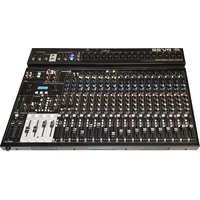
PV 5300
Powered Mixer
Congratulations on the purchase of your new PV powered mixer from Peavey. The Peavey PV 5300 is an all-in-one powered mixer, providing up to four combination XLR and 1/4 inputs using premium Peavey mic preamps, and 200 watts of peak power for crystal clear audio reproduction. The Peavey PV 5300 uses exclusive and patented features to accurately help improve tone and clarity of vocals. Our patented and revolutionary FLS Feedback Locating System quickly and easily identifies and removes feedback. Footswitchable, built-in reverb complements the already feature-packed unit. Connect almost anything to this versatile mixer via the onboard 1/4 ", RCA and 1/8 mini jacks.
Before you begin using your powered mixer, it is very important to ensure that the product has the proper AC voltage supplied. You can find the proper voltage for your amp printed next to the IEC line (power) cord on the rear panel of the unit.
Features:
- FLS® Feedback Locating System
- On-board digital reverb
- Combination XLR and 1/4 input jack
- 5-band graphic EQ with FLS®
- Master mute for channels 1-4
Footswitchable effects defeat - RCA, 1/8" media input
- Dual power amp section
RCA record outputs
LED meter bridge - Power amp sub-sonic filtering
VENTILATION: For proper ventilation, allow 6'' (15.5 cm) clearance on all sides.
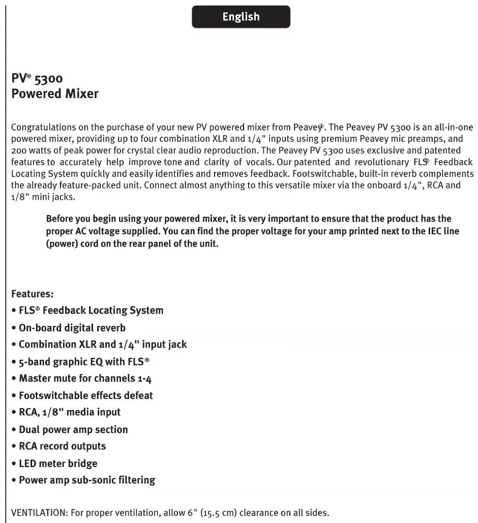
(1) HIGH (TREBLE) TONE CONTROL
An active tone control (shelving type: ± 15 dB) that varies the level of the high frequency range.
(2) LOW (BASS) TONE CONTROL
An active tone control (shelving type: ± 15 dB) that varies the level of the low frequency range.
Caution: Excessive low frequency boost causes greater power consumption and increases the possibility of speaker damage.
(3) REVERB CONTROL
This is used as a send control to the effects bus. It controls the amount of reverberation added to the input signals.
(4) LEVEL CONTROL
The level control for each channel sends the signal to the master mix bus. Typical operation is between 4 and 8 (dependent upon the input devices) but should be lower than the master level. Please remember that this acts like a preamp, so if you are using a device that has a volume output control (i.e., a tape or CD player) you will need to match the levels by adjusting the level controls on each unit.
(5)CLIPLED
Indicates when the signal level is within 3 dB of clipping.
(6) 3-PIN (XLR) LOW-IMPEDANCE MICROPHONE INPUT
This input is for typical balanced, low-impedance microphones. It will automatically provide 15V phantom power for condenser mics or active direct boxes. This has an input impedance of 1k ohms. The connector is wired as: Pin 1=shield; Pin 2=positive (hot); Pin 3=negative (cold).
(7) 1 / 4 LINE
The 1/4'' line input connector is used to connect line-level sources to the channel input. The line input is typically used for sources like keyboards and CD players and can be used with the high level output of wireless microphone receivers. When this input is used, the XLR mic input is disconnected.
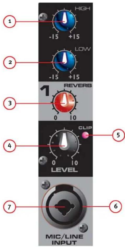
(8A) AND (8B) MEDIA INPUT
These inputs, RCA (8A) and 1 / 8'' (8B) accept a stereo input from the output of an MP3 player, CD player, tape deck or other similar device.
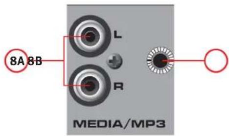
(7) FLS® FEEDBACK LOCATING SYSTEM
The patent FLS Feedback Locating System is a quick and easy way to removing feedback from the system. When feedback occurs, the LED that corresponds to the frequency band causing feedback will illuminate over the slider to be adjusted. Slowly bring that slider down until feedback is gone. The LED will remain illuminated for a few seconds after the feedback is gone. It is normal for the lights to occasionally turn on during a performance. This does not necessarily mean feedback is occurring.
(8) GRAPHIC EQ
These 5-band EQs are designed for 12dB cut or boost. These EQs are used to make minor adjustments to the overall mix and should be used sparingly.
(9)AMP LEVEL LED LADDER
These LEDs indicate the signal level going to the power amplifier. The top LED indicates LIMIT and activation of our revolutionary DDTTM speaker protection circuit, which is built into the PV 5300 and activates automatically to maximize the power amplifier without fear of distortion.
(10) MASTER VOLUME
The master level control for the main mix and the overall volume of the powered mixer.
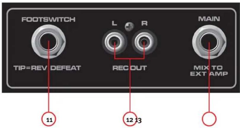
(11) FOOTSWITCH
This 1/4 jack accepts a 1/4 footswitch (Peavey part number 03051000) designed to defeat the Reverb effect on all channels.
(12)RECOUT
This RCA output provides a signal to the recording inputs of a CD recorder, stereo tape deck or other recording device.
NOTE: Do not connect a single device to both the Rec Out and Media Input (8A/8B) simultaneously this setup could create a loop which could cause severe feedback, potentially damaging your system.
(13) MAIN OUT
This 1/4 jack provides a signal from the main mix (after the graphic EQ) for an external power amplifier.
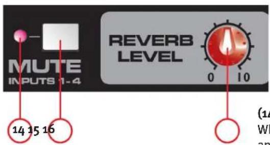
(14) MUTE LED
When this LED is illuminated it indicates channels 1-4 are muted and not passing signal to the power amplifier.
(15) MUTE SWITCH
Depressing this button mutes channels 1-4 preventing signal from passing to the power amplifier. This button does not effect channel 5. This function is convenient for breaks between performances, allowing music to be played through the sound system while muting the line/mic channels.
(16) MASTER REVERB
Overall level of the Reverb effect on corresponding channels.
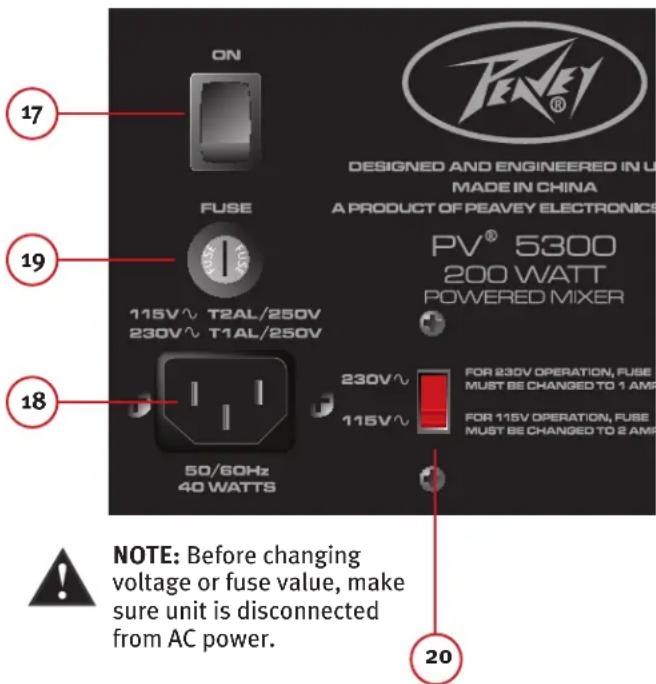
(17) POWER SWITCH
This is the main power switch.
(18) AC POWER INLET:

This is the receptacle for an IEC line cord, which provides AC power to the unit. Connect the line cord to this connector to provide power to the unit. Damage to the equipment may result if improper line voltage is used. (See line voltage marking on unit)

Never break off the ground pin on any equipment. It is provided for your safety. If the outlet used does not have a ground pin, a suitable grounding adapter should be used and the third wire should be grounded properly.
To prevent the risk of shock or fire hazard, always make sure that the amplifier and all associated equipment is properly grounded.
NOTE: FOR U.K. ONLY
As the colors of the wires in the mains lead of this apparatus may not correspond with the colored markings identifying the terminals in your plug, proceed as follows:
(1) The wire which is colored green and yellow must be connected to the terminal which is marked by the letter E, or by the Earth symbol, or colored green or green and yellow. (2) The wire which is colored blue must be connected to the terminal which is marked with the letter N, or the color black. (3) The wire which is colored brown must be connected to the terminal which is marked with the letter L, or the color red.
(19) FUSE
This is the main safety fuse for the AC line voltage. Only replace with a fuse of the exact type and rating. If the fuse continues to fail, do not replace the fuse again. Take the unit to an authorized Peavey service center.
NOTE: If the main AC voltage is changed, the fuse must also be changed to one of the appropriate rating for the voltage you are switching to.
(20) VOLTAGE SELECTOR SWITCH
This switch allows the user to select between 115VAC / 60Hz or 230VAC / 50Hz. To change the voltage selector, you must first unscrew and remove the plastic cover that protects the switch. After changing the voltage, please replace the plastic cover to ensure the voltage level is not inadvertently altered.
NOTE: The fuse MUST be changed to the appropriate value to match the voltage you have selected. Please see the note on the back of the mixer for the correct value.
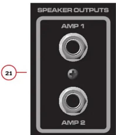
(21) SPEAKER OUTPUTS
These are two-conductor 1/4 "speaker outputs. Each one is rated at 4 ohms minimum impedance. You may connect either one 4-ohm, one 8-ohm or two 8-ohm speakers to each output. Do not operate below rated minimum impedance. For maximum power transfer, be sure to use speaker cables and not instrument cables to connect to the speakers. We recommend the use of 18-gauge or larger speaker wire.
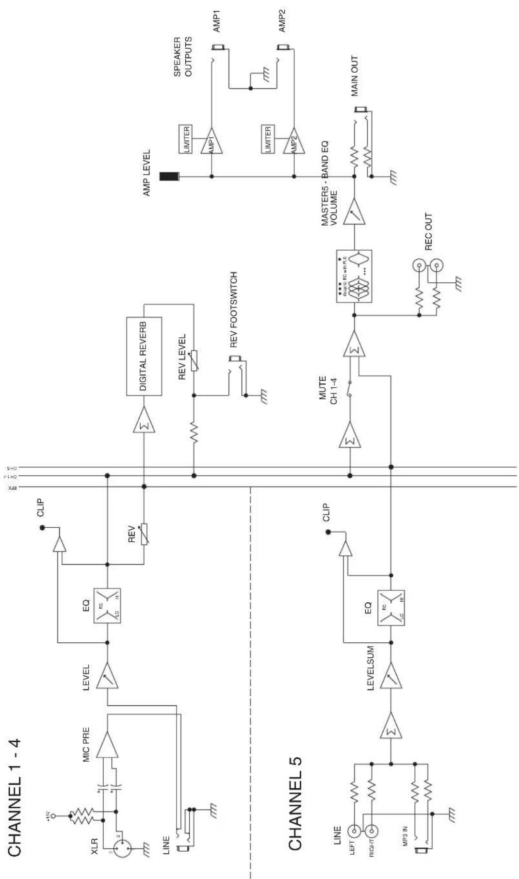
Block Diagram
Specifications
INPUT SENSITIVITY:
Mic In to full power at the power amp. Master Volume Nom.
Full Nominal
-48 dBu -28 dBu
Line In to full power at the power amp. Master Volume Nom.
Full Nominal
-18 dBu +3 dBu
CHANNEL EQ:
Shelving EQ
Low EQ 80 Hz ±15 dB
High EQ 12 kHz ±15 dB
CLIP LED:
Clip LEDs come on 3dB before clipping.
FREQUENCY RESPONSE:
All controls nominal (detent)
Mic to Main 30Hz - 20kHz + 0, - 1 dB
Line to Main 20 Hz-30 kHz +0,-1 dB
Mic to Amp 50 Hz -20 kHz +0, -3 dB
Line to Amp 40 Hz -20 kHz +0, -3 dB
NOISE:
Main = Main line output, 22 - 22kHz filter
Amp 1 = Amplifier output, loaded at 4 ohms, through AP
AUX-oo25 switching amplifier filter
All controls full down.
Main<-95dBu
Amp 1<-70 dBu
Master Volume nominal
Main<-90dBu
Amp 1<-67 dBu
THD:
All controls nominal
< 0.01% @ main line output, -30 dBu in mic input
<0.09% @ amp 1 with output adjusted to 45 Watts
All controls nominal
<0.005% @ main line output, +4 dBu in line input
0.08% @ amp 1 with output adjusted to 45 Watts
MASTER EQ:
80 Hz +/-12 dB
250 Hz +/-12 dB
1 kHz +/-12 dB
3 kHz +/-12 dB
10 kHz +/-12 dB
METER ARRAY:
LIMIT
-6 dB
-12 dB
-18 dB
-24dB
-30 dB
AMP LIMITER:
Limits amplifier power just before clipping. The limiter holds the amp power without clipping and can be driven up to 18 dB past maximum output.
AMPLIFIER OUTPUT POWER:
120VAC
Both channels loaded at 8 ohms: 30 Watts RMS per ch 6o Watts Peak per ch
Both channels loaded at 4 ohms: 50 Watts RMS per ch 100 Watts Peak per ch
POWER REQUIREMENTS:
Domestic: 120VAC 50/60Hz 40 Watts Nominal
Export: 230VAC 50/60Hz 40 Watts Nominal
SIZE:
Dimensions: H x W x D
9 ^ × 1 4 ^ × 9 ^
WEIGHT: 14 lbs.
SUBPART J OF FCC RULES. THIS DEVICE COMPLIES WITH PART 15 OF THE FCC RULES. OPERATION IS SUBJECT TO THE FOLLOWING TWO CONDITIONS (1) THIS DEVICE MAY NOT CAUSE HARMFUL INTERFERENCE, AND (2) THIS DEVICE MUST ACCEPT ANY INTERFERENCE RECEIVED, INCLUDING INTERFERENCE THAT MAY CAUSE UNDESIRED OPERATION.

Features and specifications subject to change without notice.
Peavey Electronics Corporation dot 5022 Hartley Peavey Drive dot Meridian, MS dot 39305
(601) 483-5365 • FAX (601) 486-1278 • www.peavey.com • EX 000130 • ©2011
Espanol
(11) FOOT INTERRUPTOR
As the colors of the wires in the mains lead of this apparatus may not correspond with the colored markings identifying the terminals in your plug, proceed as follows:
(1) The wire which is colored green and yellow must be connected to the terminal which is marked by the letter E, or by the Earth symbol, or colored green or green and yellow. (2) The wire which is colored blue must be connected to the terminal which is marked with the letter N, or the color black. (3) The wire which is colored brown must be connected to the terminal which is marked with the letter L, or the color red.
(19) FUSE
As the colors of the wires in the mains lead of this apparatus may not correspond with the colored markings identifying the terminals in your plug, proceed as follows:
(1) The wire which is colored green and yellow must be connected the terminal which is marked by the letter E, or by the Earth symbol, or colored green or green and yellow. (2) The wire which is colored blue must be connected to the terminal which is marked with the letter N, or the color black. (3) The wire which is colored brown must be connected to the terminal which is marked with the letter L, or the color red.
(19) FUSE
Volume principal nominal
Principal<-go dBu
Amp 1<-67 dBu
TAUX DE DISTORSION HARMONIQUE (THD) :
Exportation: 30 V CA50 / 60HZ 40 Watts Nominal
DIMENSION:
As the colors of the wires in the mains lead of this apparatus may not correspond with the colored markings identifying the terminals in your plug, proceed as follows:
(1) The wire which is colored green and yellow must be connected to the terminal which is marked by the letter E, or by the Earth symbol, or colored green or green and yellow. (2) The wire which is colored blue must be connected to the terminal which is marked with the letter N, or the color black. (3) The wire which is colored brown must be connected to the terminal which is marked with the letter L, or the color red.
(19) FUSE
(2) LOW (BASSO)-SAVYSAAT
As the colors of the wires in the mains lead of this apparatus may not correspond with the colored markings identifying the terminals in your plug, proceed as follows:
(1) The wire which is colored green and yellow must be connected to the terminal which is marked by the letter E, or by the Earth symbol, or colored green or green and yellow. (2) The wire which is colored blue must be connected to the terminal which is marked with the letter N, or the color black. (3) The wire which is colored brown must be connected to the terminal which is marked with the letter L, or the color red.
(19) FUSE
(11) FOOTSWITCH (FOTPEDAL)
As the colors of the wires in the mains lead of this apparatus may not correspond with the colored markings identifying the terminals in your plug, proceed as follows:
(1) The wire which is colored green and yellow must be connected to the terminal which is marked by the letter E, or by the Earth symbol, or colored green or green and yellow. (2) The wire which is colored blue must be connected to the terminal which is marked with the letter N, or the color black. (3) The wire which is colored brown must be connected to the terminal which is marked with the letter L, or the color red.
(19) FUSE (SAKRING)
Main = Main linjeutgang, 22 - 22kHz filter
(9) SCALA A LED AMP LEVEL
As the colors of the wires in the mains lead of this apparatus may not correspond with the colored markings identifying the terminals in your plug, proceed as follows:
(1) The wire which is colored green and yellow must be connected to the terminal which is marked by the letter E, or by the Earth symbol, or colored green or green and yellow. (2) The wire which is colored blue must be connected to the terminal which is marked with the letter N, or the color black. (3) The wire which is colored brown must be connected to the terminal which is marked with the letter L, or the color red.
(19) FUSE
Effective Date: 09/15/2010
What This Warranty Covers
Your Peavey Warranty covers defects in material and workmanship in Peavey products purchased and serviced in the U.S.A. and Canada.
What This Warranty Does Not Cover
The Warranty does not cover: (1) damage caused by accident, misuse, abuse, improper installation or operation, rental, product modification or neglect; (2) damage occurring during shipment; (3) damage caused by repair or service performed by persons not authorized by Peavey; (4) products on which the serial number has been altered, defaced or removed; (5) products not purchased from an Authorized Peavey Dealer.
Who This Warranty Protects
This Warranty protects only the original purchaser of the product.
How Long This Warranty Lasts
The Warranty begins on the date of purchase by the original retail purchaser. The duration of the Warranty is as follows:
| Product Category Duration | |
| Guitars/Basses, Amplifiers, Preamplifiers, Mixers, Electronic Crossovers and Equalizers 2 years * (+ 3 years) | |
| Drums 2 years * (+ 1 year) | |
| Enclosures 3 years * (+ 2 years) | |
| Digital Effect Devices and Keyboards and MIDI Controllers 1 years * (+ 1 year) | |
| Microphones 2 years | |
| Speaker Components 1 year(incl. Speakers, Baskets, Drivers, Diaphragm Replacement Kits and Passive Crossovers) | |
| Tubes and Meters | 90 Days |
| Cables Limited Lifetime | |
| AmpKit Link, Xport, Rockmaster Series, Strum'n Fun, RetroFire, GT & BT Series Amps | 1 year |
[* Denotes additional Warranty period applicable if optional Warranty Registration Card is completed and returned to Peavey by original retail purchaser within 90 days of purchase.]
What Peavey Will Do
We will repair or replace (at Peavey's discretion) products covered by Warranty at no charge for labor or materials. If the product or component must be shipped to Peavey for Warranty service, the consumer must pay initial shipping charges. If the repairs are covered by Warranty, Peavey will pay the return shipping charges.
How To Get Warranty Service
(1) Take the defective item and your sales receipt or other proof of date of purchase to your Authorized Peavey Dealer or Authorized Peavey Service Center.
OR
(2) Ship the defective item, prepaid, to Peavey Electronics Corporation, International Service Center, 412 Highway 11 & 80 East, Meridian, MS 39301. Include a detailed description of the problem, together with a copy of your sales receipt or other proof of date of purchase as evidence of Warranty coverage. Also provide a complete return address.
Limitation of Implied Warranties
ANY IMPLIED WARRANTY, INCLUDING WARRANTY OF MERCHANTABILITY AND FITNESS FOR A PARTICULAR PURPOSE, ARE LIMITED IN DURATION TO THE LENGTH OF THIS WARRANTY.
Some states do not allow limitations on how long an implied Warranty lasts, so the above limitation may not apply to you.
Exclusions of Damages
PEAVEY'S LIABILITY FOR ANY DEFECTIVE PRODUCT IS LIMITED TO THE REPAIR OR REPLACEMENT OF THE PRODUCT, AT PEAVEY'S OPTION. IF WE ELECT TO REPLACE THE PRODUCT, THE REPLACEMENT MAY BE A RECONDITIONED UNIT. PEAVEY SHALL NOT BE LIABLE FOR DAMAGES BASED ON INCONVENIENCE, LOSS OF USE, LOST PROFITS, LOST SAVINGS, DAMAGE TO ANY OTHER EQUIPMENT OR OTHER ITEMS AT THE SITE OF USE, OR ANY OTHER DAMAGES WHEHTHER INCIDENTAL, CONSEQUENTIAL OR OTHERWISE, EVEN IF PEAVEY HAS BEEN ADVISED OF THE POSSIBILITY OF SUCH DAMAGES.
Some states do not allow the exclusion or limitation of incidental or consequential damages, so the above limitation may not apply to you.
This Warranty gives you specific legal rights, and you may also have other rights which vary from state to state.
If you have any questions about this Warranty or services received or if you need assistance in locating an Authorized Service Center, please contact the Peavey International Service Center at (601) 483-5365.
Features and specifications are subject to change without notice.
Optional Product Extended Warranty Registration
Give us some information and put your extended warranty into effect!
Please take a few minutes to fill out this information/survey sheet to help us get to know and serve you better.
To save time, submit your warranty registration online at www.peavey.com/support/warrantyregistration
1.
First Name
Initial
Last Name
Street Address
City
State/Province
Postal Code
( )
Telephone Number
E-mail Address
( )
Fax Number
Date of Birth
Gender
M
2.

Model
8-Digit Serial Number
Date of Purchase
Price Paid
3.
Name of store where purchased
City
State
- Top two (2) reasons why you purchased from this store/dealer:
Availability of product
Past favorable experience
Friend/Relative's recommendation
Best price
Store credit card
□Advertised special
Knowledgeable staff
Convenient location
Availability of lessons
Received as a gift
Technical instruction
□ Other
- Where do you most often shop for music and sound products?
Independent retailer
Newspaper ads
Mass market retailer
Internet/Web sites
Mail order magazines
Other
- What two (2) factors most influenced your purchase of this product?
Peavey brand name
Product appearance
Craftsmanship
Durability
Features for price
Prior experience with Peavey
Bundled accessories
□ Packaging
Sound quality
□ Other
- How did you learn about this Peavey product? (select best answer)
Magazine review
Teacher's recommendation
Newspaper review
Catalog or flyer
Radio advertisement
Saw in store
□Advertised special
Use by professional
□ Friend/Relative's recommendation
Other
Salesperson's recommendation

-
Which other brands/models did you consider?
-
How would you describe your level of musicianship/technical expertise?
Beginner - Never played or taken less than one (1) year of lessons
Intermediate - One (1) to five (5) years of lessons or playing
Advanced - More than five (5) years of lessons or playing; play professionally
- Education: (select best answer)
High school
Some college
Completed college
Graduate school
- Which best describe your family income? (select best answer)
Under $15,000
□75,000-99,999
□15,000-24,999
□ 100,000 -149,999
□25,000-34,999
Over - $150,000
□35,000-49,999
□50,000-74,999
- Which of the following is your primary source of information on musical products: (select best answer)
Television
□ Mail order catalogs
□ Radio
Direct mail
□Internet
Literature from manufacturer
Newspaper
□ Other
Magazines
- What is your main motivation for buying new equipment?
□ Replacing old product
Impulse
Want new and leading edge
Need for improved performance
equipment
New technology
Fullfill a specific need
Availability of product
Supplement existing products
□ Other
Value
-
Please list your three most frequently visited Web sites.
-
http://
- http://
-
http://
-
In your opinion, what could Peavey do to improve its products and/or service? Please use the space below to tell us your answer.
8019-20066 m W
80LSxOg'Od
Aeae eae aee
ononee eae

H
6eIsod
oeid


- IMPORTANT SAFETY INSTRUCTIONS
- FCC Compliancy Statement
- Responsible Party:
- English
- PV 5300
- Powered Mixer
- Features:
- HIGH (TREBLE) TONE CONTROL
- LOW (BASS) TONE CONTROL
- REVERB CONTROL
- LEVEL CONTROL
- (5)CLIPLED
- 3-PIN (XLR) LOW-IMPEDANCE MICROPHONE INPUT
- 1 / 4 LINE
- (8A) AND (8B) MEDIA INPUT
- FLS® FEEDBACK LOCATING SYSTEM
- GRAPHIC EQ
- (9)AMP LEVEL LED LADDER
- MASTER VOLUME
- FOOTSWITCH
- (12)RECOUT
- MAIN OUT
- MUTE LED
- MUTE SWITCH
- MASTER REVERB
- POWER SWITCH
- AC POWER INLET:
- NOTE: FOR U.K. ONLY
- FUSE
- VOLTAGE SELECTOR SWITCH
- SPEAKER OUTPUTS
- Specifications
- INPUT SENSITIVITY:
- CHANNEL EQ:
- CLIP LED:
- FREQUENCY RESPONSE:
- NOISE:
- THD:
- MASTER EQ:
- METER ARRAY:
- AMP LIMITER:
- AMPLIFIER OUTPUT POWER:
- POWER REQUIREMENTS:
- SIZE:
- Espanol
- FOOT INTERRUPTOR
- TAUX DE DISTORSION HARMONIQUE (THD) :
- DIMENSION:
- LOW (BASSO)-SAVYSAAT
- FOOTSWITCH (FOTPEDAL)
- FUSE (SAKRING)
- SCALA A LED AMP LEVEL
- What This Warranty Covers
- What This Warranty Does Not Cover
- Who This Warranty Protects
- How Long This Warranty Lasts
- What Peavey Will Do
- How To Get Warranty Service
- OR
- Limitation of Implied Warranties
- Exclusions of Damages
- Optional Product Extended Warranty Registration
Brand : PEAVEY
Model : PV 5300
Category : Mixer