PVi 6500 - Mixer PEAVEY - Free user manual and instructions
Find the device manual for free PVi 6500 PEAVEY in PDF.

| Type | Powered Mixer |
| Channels | 8 |
| Power Output | 650W (4Ω bridged) |
| Frequency Response | 20Hz - 20kHz |
| Inputs | 8 XLR/¼" combo jacks |
| Equalization | 3-band per channel (High, Mid, Low) |
| Built-in Effects | 24-bit digital effects (16 presets) |
| Outputs | Main L/R, Monitor, Phones |
| Phantom Power | +48V (global) |
| Power Supply | 120V AC, 60Hz |
| Dimensions (W x D x H) | 20" x 18" x 6" |
| Weight | 35 lbs |
| Protection | Short circuit, thermal overload |
| Cooling | Variable speed fan |
| Construction | Steel chassis with aluminum handles |
| Cleaning | Dry, lint-free cloth; avoid solvents |
| Maintenance | No user-serviceable parts inside |
| Repairability | Authorized Peavey service centers |
| Warranty | 2 years limited |
| Included Accessories | Power cord, user manual |
Frequently Asked Questions - PVi 6500 PEAVEY
User questions about PVi 6500 PEAVEY
0 question about this device. Answer the ones you know or ask your own.
Ask a new question about this device
Download the instructions for your Mixer in PDF format for free! Find your manual PVi 6500 - PEAVEY and take your electronic device back in hand. On this page are published all the documents necessary for the use of your device. PVi 6500 by PEAVEY.
USER MANUAL PVi 6500 PEAVEY
Intended to alert the user to the presence of uninsulated “dangerous voltage” within the product’s enclosure that may be of sufficient magnitude to constitute a risk of electric shock to persons.
Intended to alert the user of the presence of important operating and maintenance (servicing) instructions in the literature accompanying the product.
CAUTION: Risk of electrical shock — DO NOT OPEN!

CAUTION: To reduce the risk of electric shock, do not remove cover. No user serviceable parts inside. Refer servicing to qualified service personnel.
WARNING: To prevent electrical shock or fire hazard, this apparatus should not be exposed to rain or moisture, and objects filled with liquids, such as vases, should not be placed on this apparatus. Before using this apparatus, read the operating guide for further warnings.

Protective earthing terminal. The apparatus should be connected to a mains socket outlet with a protective earthing connection.

IMPORTANT SAFETY INSTRUCTIONS
WARNING: When using electrical products, basic cautions should always be followed, including the following:
-
Read these instructions.
-
Keep these instructions.
-
Heed all warnings.
-
Follow all instructions.
-
Do not use this apparatus near water.
-
Clean only with a dry cloth.
-
Do not block any of the ventilation openings. Install in accordance with manufacturer's instructions.
-
Do not install near any heat sources such as radiators, heat registers, stoves or other apparatus (including amplifiers) that produce heat.
-
Do not defeat the safety purpose of the polarized or grounding-type plug. A polarized plug has two blades with one wider than the other. A grounding type plug has two blades and a third grounding plug. The wide blade or third prong is provided for your safety. If the provided plug does not fit into your outlet, consult an electrician for replacement of the obsolete outlet.
-
Protect the power cord from being walked on or pinched, particularly at plugs, convenience receptacles, and the point they exit from the apparatus.
-
Only use attachments/accessories provided by the manufacturer.
-
Use only with a cart, stand, tripod, bracket, or table specified by the manufacturer, or sold with the apparatus. When a cart is used, use caution when moving the cart/apparatus combination to avoid injury from tip-over.
-
Unplug this apparatus during lightning storms or when unused for long periods of time.
-
Refer all servicing to qualified service personnel. Servicing is required when the apparatus has been damaged in any way, such as power-supply cord or plug is damaged, liquid has been spilled or objects have fallen into the apparatus, the apparatus has been exposed to rain or moisture, does not operate normally, or has been dropped.
-
Never break off the ground pin. Write for our free booklet "Shock Hazard and Grounding." Connect only to a power supply of the type marked on the unit adjacent to the power supply cord.
-
If this product is to be mounted in an equipment rack, rear support should be provided.
-
Note for UK only: If the colors of the wires in the mains lead of this unit do not correspond with the terminals in your plug, proceed as follows: a) The wire that is colored green and yellow must be connected to the terminal that is marked by the letter E, the earth symbol, colored green or colored green and yellow. b) The wire that is colored blue must be connected to the terminal that is marked with the letter N or the color black. c) The wire that is colored brown must be connected to the terminal that is marked with the letter L or the color red.
-
This electrical apparatus should not be exposed to dripping or splashing and care should be taken not to place objects containing liquids, such as vases, upon the apparatus.
-
The on/off switch in this unit does not break both sides of the primary mains. Hazardous energy can be present inside the chassis when the on/off switch is in the off position. The mains plug or appliance coupler is used as the disconnect device, the disconnect device shall remain readily operable.
-
Exposure to extremely high noise levels may cause a permanent hearing loss. Individuals vary considerably in susceptibility to noise-induced hearing loss, but nearly everyone will lose some hearing if exposed to sufficiently intense noise for a sufficient time. The U.S. Government's Occupational Safety and Health Administration (OSHA) has specified the following permissible noise level exposures:
Duration Per Day In Hours Sound Level dBA, Slow Response
| 8 90 | |
| 6 92 | |
| 4 95 | |
| 3 97 | |
| 2 100 | |
| 1 1/2 102 | |
| 1 105 | |
| 1/2 | 110 |
| 1/4 or less 115 |
According to OSHA, any exposure in excess of the above permissible limits could result in some hearing loss. Earplugs or protectors to the ear canals or over the ears must be worn when operating this amplification system in order to prevent a permanent hearing loss, if exposure is in excess of the limits as set forth above. To ensure against potentially dangerous exposure to high sound pressure levels, it is recommended that all persons exposed to equipment capable of producing high sound pressure levels such as this amplification system be protected by hearing protectors while this unit is in operation.
SAVE THESE INSTRUCTIONS!
a) The wire that is colored green and yellow must be connected to the terminal that is marked by the letter E, the earth symbol, colored green or colored green and yellow.
b) The wire that is colored blue must be connected to the terminal that is marked with the letter N or the color black.
c) The wire that is colored brown must be connected to the terminal that is marked with the letter L or the color red.
Logo referenced in Directive 2002/96/EC Annex IV(OJ(L)37/38,13.02.03 and defined in EN 50419: 2005
The bar is the symbol for marking of new waste and is applied only to equipment manufactured after 13 August 2005
Correct Disposal of this product. This marking indicates that this product should not be disposed with other house hold wastes throughout the EU. To prevent possible harm to the environment or human health from uncontrolled waste disposal, recycle it responsibly to promote the sustainable reuse of material resources. To return your used device, please use the return and collection systems, or contact the retailer where the product was purchased. They can take this product for environmental safe recycling.

FCC Compliancy Statement
This device complies with Part 15 of the FCC rules. Operation is subject to the following two conditions: (1) this device may not cause harmful interference, and (2) this device must accept any interference received, that may cause undesired operation.
Warning: Changes or modifications to the equipment not approved by Peavey Electronics Corp. can void the user's authority to use the equipment.
Note - This equipment has been tested and found to comply with the limits for a Class B digital device, pursuant to Part 15 of the FCC Rules. These limits are designed to provide reasonable protection against harmful interference in a residential installation. This equipment generates, uses and can radiate radio frequency energy and, if not installed and used in accordance with the instructions, may cause harmful interference to radio communications. However, there is no guarantee that interference will not occur in a particular installation. If this equipment does cause harmful interference to radio or television reception, which can be determined by turning the equipment off and on, the user is encouraged to try and correct the interference by one or more of the following measures.
- Reorient or relocate the receiving antenna.
- Increase the separation between the equipment and receiver.
- Connect the equipment into an outlet on a circuit different from that to which the receiver is connected.
- Consult the dealer or an experienced radio/TV technician for help.
Responsible Party:
Peavey Electronics Corporation • 5022 Hartley Peavey Drive • Meridian, MS • 39305
(601) 483-5365 • FAX (601) 486-1278 • www.peavey.com • 80305780 • ©2011

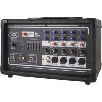
Powered Mixers
Congratulations on the purchase of your new PV powered mixer from Peavey ^® . The Peavey PV ^® 6500 is a revolutionary all in one powered mixer. It provides everything a musician needs including up to six combination XLR and 1/4" inputs using Peavey's award winning mic preamps, and 400 watts of peak power for crystal clear audio reproduction. The Peavey PV ^® 6500 uses exclusive and patented features like Mid Morph ^® to accurately help improve tone and clarity of vocals. Feedback is quickly and easily identified and removed with Peavey's 9 band graphic EQ combined with our patented revolutionary FLS ^® Feedback Locating System. The PV ^® 6500 is equipped with Peavey's exclusive Kosmos ^® -C technology, which drastically enhances both the low and high end of the audio spectrum. Footswitchable, built-in 24-bit digital effects complement the already feature packed unit. Connect almost anything to this versatile mixer via the onboard 1/4", RCA and 1/8" mini jacks. The PV ^® 6500 includes a dock that allows the users to remotely play and pause pre-recorded music.
Before you begin using your powered mixer it is very important to ensure that the product has the proper AC voltage supplied. You can find the proper voltage for your amp printed next to the IEC line (power) cord on the rear panel of the unit.

FEATURES:
• FLSFeedback Locating System
- Mid-Morph EQ
- Kosmos-C
- On-board 24-bit digital effects with mute button
• Digital effects parameter control
- Combination XLR and 1/4" input jacks
• 9-Band Graphic EQ with FLS
• Master Mute for channels 1-5
- Footswitchable effects defeat
• 15 Volt Phantom Power
• RCA, 1/8" Media input
- Selectable Main or Monitor dual power section
- RCA Record outputs
- LED Meter bridge
• Power amp sub-sonic filtering
- Clip light and signal presence indicator
- Main line level 1/4" output
- DDT ^TM Speaker protection circuit
• SD card & USB MP3 player
- Bluetooth® player

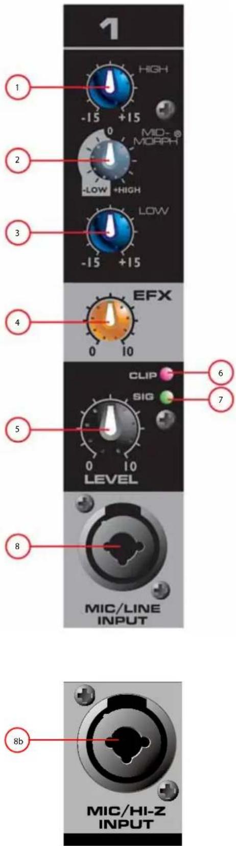
CHANNEL CONTROLS
HIGH EQ
This High EQ shelving type of active tone control varies the treble frequencies (+/- 15dB at 12kHz) and is designed to remove noise or add brilliance to the signal, depending on the quality of the source.
MID-MORPH® EQ
Where most mid-range controls work at just one frequency, the Mid-Morph works at two. When turned counterclockwise, it cuts at 250 Hz to reduce frequencies that muddy the sound. When turned clockwise, it boosts at 4 kHz to add intelligibility to vocals. Either way, improved vocal or instrument definition can be achieved.
LOW EQ
A shelving type of EQ that varies the bass frequency levels (+/-15dB at 80Hz). Low EQ adds depth to thin-sounding signals or cleans up the muddy ones. As with any EQ, use sparingly. Too much of this EQ can give you a booming bottom end.
EFX - DIGITAL EFFECTS
This control adjusts the level of the channel signal added to the effects mix. The signal is sent to the internal effects processor. Turning the knob to the left (0) will turn off effects on the associated channel, while turning the knob to the right will increase the amount of the selected effect.
LEVEL
This control sets the signal level sent to the main mix.
CLIP
When this LED turns or blinks red, it is an indication that the signal coming into the channel is too strong, potentially causing distortion. Turn down the Level control (5) until the Clip light is no longer present. If you are having difficulty getting a clean signal, try varying the output of the connected device.
SIG
When this LED is green, it is an indication the mixer is receiving signal at the input of the channel. If you are having trouble getting sound out of the mixer and this LED is not on, check the microphone, instrument or cable that is connected to the channel.
MIC/LINE INPUT
This combination input jack can accept either a 1/4" (balanced or unbalanced) input or an XLR balanced, low-impedance connection. The tip is positive on the 1/4" balanced input, and pin 2 is positive on the XLR.
MIC/HI Z INPUT
Channel 5 line input is a Hi-Z unbalanced input for use with high impedance microphones, acoustic/electric guitars or other high impedance sources equipped with a 1/4" plug (TS).
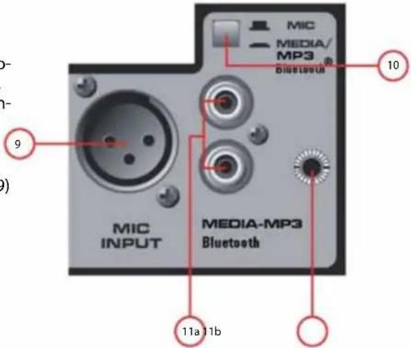
XLR BALANCED INPUT
Channel 6 is designed specifically for pre-recorded (program) music, but can also be used with a microphone. This XLR input provides a balanced low impedance connection.
MIC OR MEDIA SELECT BUTTON
This control selects between the low impedance XLR (9) and the RCA / 1/8", or USB MP3/Bluetooth® input.
11a/11b. MEDIA INPUT
These RCA and 1/8" inputs accept a stereo input from the output of an MP3 player, CD player, tape deck or other similar device.
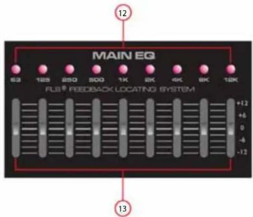
FLS®
When feedback occurs, the LED of the frequency closest to the frequency that is feeding back will illuminate over the slider to be adjusted. Slowly bring the corresponding slider down until feedback is gone. The LED will remain illuminated for a few seconds after the feedback is gone.
GRAPHIC EQ
These 9-band EQs are designed for 12dB cut or boost. These EQs are used to make minor adjustments to the overall mix and should be used sparingly.
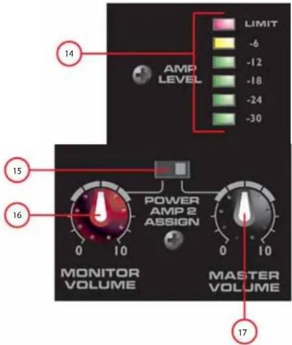
AMP LEVEL LED LADDER
These LEDs indicate the signal level going to the power amplifier. The top LED indicates LIMIT and activation of our revolutionary DDT™ speaker protection circuit. Peavey's award winning speaker protection circuit is built into the PV® 6500MP3 and activated automatically to maximize the power amplifier without fear of distortion.
POWER AMP INPUT SELECT
This control allows the user to select whether the 2nd power amplifier receives its signal from the Master Volume (17) control or from the Monitor Volume (16) control. This allows the user to run both power amps for mains at the same level, or use power amp 1 for mains and power amp 2 for monitors with independent level controls.
MONITOR VOLUME
An independent volume control that is active only when switch 15 is placed in the LEFT position. This allows the user independent volume control over the two internal power amplifiers. This is especially convenient when using power amp 2 to drive monitor speakers.
MASTER VOLUME
The master level control for the main mix and the overall volume of the powered mixer. When switch 15 is in the RIGHT position, the master volume controls both internal power amplifiers.

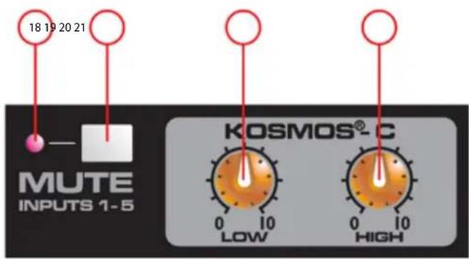
MASTER MUTE LED
When the LED is ON it indicates the master mute is activated.
MASTER MUTE
Depressing this button mutes channels one through five, preventing signal from passing to the power amplifier. This button does not affect channel 6.
KOSMOS®-C
The Kosmos-C module uses special circuitry to enrich the sound of your system. The LOW control is not just a simple bass boost. It provides 'natural bass enhancement' by adding harmonically related bass signals that track envelope of the original signal. The Kosmos-C HIGH control can be used to add clarity to dull signals.
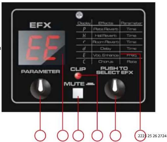
EFFECTS TYPE TABLE
This table lists the types of effects available and the abbreviation used for each effect in the first character of the LED display. The chart also lists the parameter associated with each effect, which is controlled by turning encoder 24. A more detailed list of effects can be found at the end of this manual.
EFX LED
This LED indicates the type of effect currently selected. When turning encoder 27 the display will flash until the encoder is depressed, selecting a new effect.
PARAMETER CONTROL
This encoder controls the parameter associated with the selected effect, listed both on the mixer (22) and in this manual. The parameter control is used to make adjustments to the sound of the effect.
EFX MUTE
When pushed this button bypasses the effects section, letting the user listen to the dry signal. When depressed and muted, LED 23 displays two dashes “--”.
CLIP LED
This LED blinks RED when the signal to the effects section is too hot and is causing distortion. Find the source of the hot signal by reducing the EFX SEND (4) on each channel until the LED is no longer clipping (blinking red).
EFFECTS SELECT
Turn and push this encoder to select the desired effect.
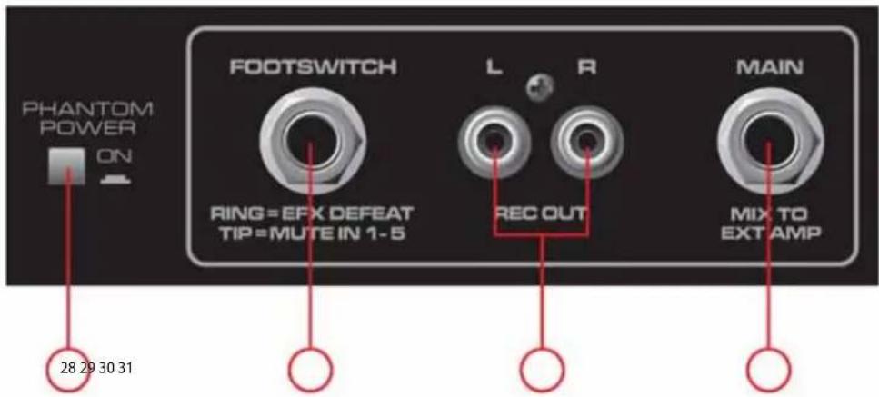
PHANTOM POWER
When depressed, this switch applies +15 VDC to all input XLR connectors to power microphones that require phantom power.
Caution: When phantom power is switched on, make sure that any channel you are plugging a microphone into is turned down and the Master Main and Monitor controls are set to minimum. Otherwise, there will be a loud pop in the system. For best results, first plug all microphones into their respective channels before phantom power is switched on. This reduces noise through the system and reduces the chance of damage to the microphones. If phantom power is used, do not connect unbalanced, dynamic microphones or other devices to the XLR inputs that cannot handle this voltage. (Some wireless receivers may be damaged. Consult their manuals.) The line input jacks are not connected to the phantom supply and are safe for all inputs (balanced or unbalanced). An unbalanced to balanced impedance converter such as the Peavey 5116 or a Peavey 1:1 Interface Adapter may also be used to isolate a microphone from phantom voltage.
FOOTSWITCH
This 1/4" TRS (tip ring sleeve) jack accepts a momentary 1/4" TRS dual button footswitch (Peavey part number 03014070) designed to defeat the effects on all channels and activate the MASTER MUTE switch (19).
RCA RECORD OUT
This pair of RCA jacks provides a signal to the recording inputs of a CD recorder, stereo tape deck, or other recording device.
NOTE: Do not connect a single device to the Media In (11a/11b) and Record Out (30). This improper setup forms a loop, which can cause severe feedback. Use separate devices for recording and playback.
MAIN OUT
This 1/4" jack provides a signal from the main mix (after the graphic EQ) for an external power amplifier. An external power amp, such as our IPR series of amplifiers, can then drive additional speakers.
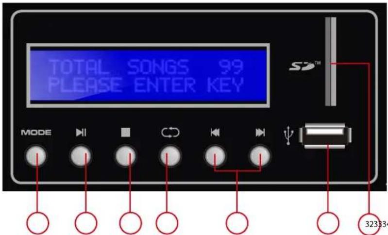
323334 35 36 37 38
SD CARD SLOT
To connect the SD card, push the card completely in the slot until it clicks into place. The player will accept a SD card up to 32Gb in size.
USB disk SLOT
On the right side of the device is a USB drive slot where a USB memory stick can be connected. The player will accept a memory stick up to 32Gb.
MODE
If both, a memory stick and SD card are present, a short press of the MODE button will change between the USB input and the SD card input. A long press of the MODE button will shut off the MP3 player. Another long press is needed to turn it back on.
PLAY/PAUSE
A short press of the PLAY/PAUSE button causes the operation to change from PLAY to PAUSE or from PAUSE back to PLAY. A long press of the PLAY/PAUSE button will put the player into navigation mode. When in navigation mode the player can toggle between multiple folders on the memory device. The file folder num is displayed at the top of the screen while the file folder name is at the bottom. The "track skip (38)" buttons can be used to toggle between the folders on the memory device. Once the desired folder is found, press "PLAY/PAUSE" to select the folder. The first song in the folder will begin playing.
STOP
Press the STOP button to stop a file that is playing.
REPEAT
Pressing the REPEAT button toggles the function between ALL, RANDOM and SINGLE.
ALL: Repeats all songs.
RANDOM: Plays songs in random order.
SINGLE: Repeats a single song.
Note: The REPEAT functions only apply to the songs in the selected folder.
TRACK SKIP
In playback mode the TRACK SKIP buttons let you select the track to play.
A short press skips to the next track. A long press allows you to fast forward/rewind through a song. Hold the button down until the desired playback point is found. Release the button and the song will start playing.
In navigation mode, the TRACK SKIP buttons are used to increment/decrement through the folders on the memory device.

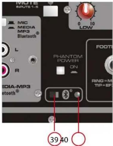
Bluetooth® Switch
Turns the Bluetooth on and off. Slide the switch to the right to turn the Bluetooth feature on.
Bluetooth® indicator LED
Indicates the status of the Bluetooth function.
To listen to your music via Bluetooth wireless connection, you need to pair (link) your PV®i 6500 with your Bluetooth phone and/or music device.
- Turn off any Bluetooth devices previously paired with your PV®i 6500.
- Turn on the Bluetooth feature on your phone or music device.
- Slide the switch (39) to the right to turn on the Bluetooth feature. The Bluetooth LED will flash to indicate your PV®i 6500 is in discoverable mode.
- Place your phone or music device in Bluetooth search mode.
The phone or music device will now begin searching for your PV®i 6500.
- Select Bluetooth audio from search results on your phone or music device.
- Select OK or Yes to pair your speaker system with your phone or music device.
When your PV®i 6500 successfully pairs and connects with your phone or music device, the Bluetooth indicator changes from flashing green to steadily lit. You will now be able to play music from your connected music source through your PV®i 6500. The level can either be adjusted from the connected source or by the level control in Channel 6.
* Wireless range can vary depending on Bluetooth class of source device, and be subject to interference from obstructions such as walls or other electronic devices.


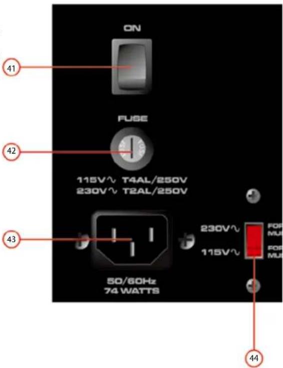
POWER SWITCH
This is the main power switch.
FUSE
This is the main safety fuse for the AC line voltage. Only replace with a fuse of the exact type and rating. If the fuse continues to open, do not over fuse. Take the unit to an authorized Peavey service center.
NOTE: If the main AC voltage is changed, the fuse must also be changed to one of the appropriate rating for the voltage you are switching to.
AC POWER INLET
This is the receptacle for an IEC line cord, which provides AC power to the unit. Connect the line cord to this connector to provide power to the unit. Damage to the equipment may result if improper line voltage is used. (See line voltage marking on unit).
Never break off the ground pin on any equipment. It is provided for your safety. If the outlet used does not have a ground pin, a suitable grounding adapter should be used and the third wire should be grounded properly. To prevent risk of shock or fire hazard, always make sure that the amplifier and all associated equipment is properly grounded.
NOTE: FOR UK ONLY
As the colors of the wires in the mains lead of this apparatus may not correspond directly with the colored markings identifying the terminals in your plug, proceed as follows: (1) The green and yellow wire must be connected to the terminal which is marked with the letter E, or by the earth symbol, or is colored green, or green and yellow. (2) The blue wire must be connected to the terminal which is marked with the letter N, or the color black. (3) The brown wire must be connected to the terminal which is marked with the letter L, or the color red.
VOLTAGE SELECTOR SWITCH
This switch allows the user to select between 115VAC / 60Hz or 230VAC / 50Hz. To change the voltage selector, you must first unscrew and remove the plastic cover that protects the switch. After changing the voltage, please replace the plastic cover to ensure the voltage level is not inadvertently altered.
NOTE: The fuse MUST be changed to the appropriate value to match the voltage you have selected. Please see the note on the back of the mixer for the correct value.
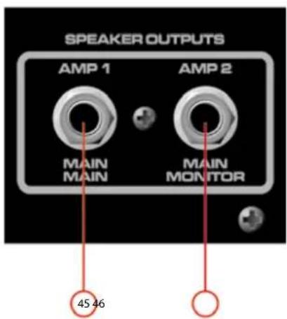
MAIN / MONITOR SPEAKER OUTPUTS
These are two-conductor 1/4" speaker outputs. Each one is rated at 4 ohms minimum impedance. You may connect either one 4-ohm, one 8-ohm or two 8-ohm speakers to each output. Do not operate below rated minimum impedance. For maximum power transfer, be sure to use speaker cables and not instrument cables to connect to the speakers. We recommend the use of 18-gauge or larger speaker wire.
| PLATE (TIME) | DESCRIPTION | PREDELAY DAMP FACTOR | ROOM | ROOM SIZE | FRONT END HP | BACK END LP | MORE DESCRIPTIVE NAME |
| P1 | Bright | 35 ms | |||||
| P2 | Gentle LP | 48 ms | |||||
| P3 | Med LP | 62 ms | |||||
| P4 | Hard LP | 78 ms | |||||
| P5 | Dark | 95 ms | |||||
| HALL (TIME) | |||||||
| H1 | Vox Fox | 35 ms | Med | Med | Subtle | Subtle | Med Hall |
| H2 | Vox Huge | 42 ms | Med | Large | Subtle | Subtle | Cathedral |
| H3 | Vox Glow | 10 ms | Med | Large | Subtle | Subtle | Auditorium |
| H4 | Strings | 30 ms | Med | Med | Subtle | Subtle | Concert Hall |
| H5 | Brass Hall | 35 ms | High | Med | Subtle | Moderate | Concert Hall 2 |
| ROOM (TIME) | |||||||
| R1 | Vox Air | 30 ms | Low | Small | Aggressive | Subtle | Hard Walls |
| R2 | Vox Club | 35 ms | High | Small | Subtle | Moderate | Club |
| R3 | Snare Low | 70 ms | Low | Small | Moderate | Subtle | Bathroom |
| R4 | AC GTR | 42 ms | Med | Small | Moderate | Subtle | Med Walls |
| R5 | Brass Room | 40 ms | High | Med | Subtle | Moderate | Med Room Damped Walls |
| DELAY (TIME) | |||||||
| D1 | Double | ||||||
| D2 | Slapback | ||||||
| D3 | Bright, Few Repeats | ||||||
| D4 | Bright, More Repeats | ||||||
| D5 | Bright, Most Repeats | ||||||
| D6 | Dark, Few Repeats | ||||||
| D7 | Dark, More Repeats | ||||||
| D8 | Dark, Most Repeats | ||||||
| ENHANCE (CUTOFF FREQ) | |||||||
| E1 | Light Harmonics | ||||||
| E2 | Moderate Harmonics | ||||||
| E3 | Heavy Harmonics | ||||||
| CHORUS (RATE) | PREDELAY | CHORUSTIME | RATE | MODULATION | |||
| C1 | High Depth, Slow Rate | 10 ms | 20 ms | 0.1 – 1 Hz | Random Sine | ||
| C2 | Mod Depth, Wide Rate | 10 ms | 5 ms | 0.5 - 4 Hz | Random Sine | ||
| C3 | Short Depth, Wide Rate | 10 ms | 2 ms | 0.5 - 6 Hz | Sine | ||
| C4 | Short Depth, Fast Rate | 5 ms | 1 ms | 5 - 15 Hz | Random Sine | ||
| C5 | High Depth, Mod Rate | 2 ms | 20 ms | 0.2 - 3 Hz | Random Sine | ||
flowchart
graph TD
    subgraph Channel 1 - 4
        A["REC out"] --> B["Master volume"]
        C["MAIN out"] --> B
        D["AMPI"] --> E["Inner level"]
        F["AMPI2"] --> G["Monitor volume"]
        H["MINER"] --> I["Master volume"]
        J["Spaker outputs"] --> K["AMPS ASSIGN"]
        L["AMPS"] --> M["H Pasos"]
        N["KOSMOS - C"] --> O["LOW HIGH"]
        P["MUTE CH 1.5-9 - BAND EO"] --> Q["MUTE CH 1.5-9 - BAND EO"]
    end

    subgraph Channel 5 - 2
        R["EFX"] --> S["Digital EFX"]
        T["DEFEA"] --> S
        U["CUP"] --> S
        V["ERR"] --> S
        W["ERR"] --> S
        X["ERR"] --> S
        Y["ERR"] --> S
        Z["ERR"] --> S
    end

    subgraph Channel 6
        AA["ELV"] --> AB["BLUTTOOH"]
        AC["SUN"] --> AD["Level"]
        AE["MPC PLAY"] --> AF["BLUTTOOH + 15V"]
        AG["MPC PI"] --> AH["Level"]
        AI["LINE"] --> AJ["MPC PLAY"]
        AK["XUR"] --> AL["MPC PLAY"]
        AM["MPC PRE"] --> AN["MPC PLAY"]
    end

    subgraph Channel 5 - 3
        AO["ELV"] --> AP["BLUTTOOH"]
        AQ["SUN"] --> AR["Level"]
        AS["MPC PLAY"] --> AT["MPC PLAY"]
        AU["LINE"] --> AV["MPC PLAY"]
        AW["XUR"] --> AX["MPC PLAY"]
        AY["MPC PI"] --> AZ["MPC PLAY"]
        BA["MPC PRE"] --> BB["MPC PLAY"]
    end

    subgraph Channel 6
        BC["ELV"] --> BD["BLUTTOOH"]
        BE["SUN"] --> BF["Level"]
        BG["MPC PLAY"] --> BH["MPC PLAY"]
        BI["LINE"] --> BJ["MPC PLAY"]
        BK["XUR"] --> BL["MPC PLAY"]
        BM["MPC PRE"] --> BN["MPC PLAY"]
    end

    subgraph Channel 5 - 1
        BO["ELV"] --> BP["BLUTTOOH"]
        BQ["SUN"] --> BR["Level"]
        BS["MPC PLAY"] --> BT["MPC PLAY"]
        BU["LINE"] --> BV["MPC PLAY"]
        BW["XUR"] --> BX["MPC PLAY"]
        BY["MPC PRE"] --> BZ["MPC PLAY"]
    end

    subgraph Channel 5 - 2
        CA["ELV"] --> CB["BLUTTOOH"]
        CC["SUN"] --> CD["Level"]
        DD["MPC PLAY"] --> DE["BUX"]
        DF["MPC PRE"] --> DG["BUX"]
    end

    subgraph Channel 5 - 1
        BEQ["ELV"] --> BFQ["BLUTTOOH + 15V"]
        BGQ["SUN"] --> BHQ["Level"]
        BIQ["MPC PLAY"] --> BRQ["MPC PLAY"]
        BQL["XUR"] --> BNQ["MPC PLAY"]
    end
Specifications
INPUT SENSITIVITY:
Mic In to full power at the power amp. Master Volume Nom.
Full
Nominal
-40 dBu -22 dBu
Line In to full power at the power amp. Master Volume Nom.
Full
Nominal
-10 dBu +8 dBu
CHANNEL EQ:
Shelving EQ
Low EQ 80 Hz ±15 dB
Mid-Morph
Low 250 Hz ±15 dB
High 4 kHz ±15 dB
High EQ 12 kHz ±15 dB
CLIP LED:
Clip LEDs come on 3 dB before clipping.
FREQUENCY RESPONSE:
All controls nominal (detent)
Mic to Main 20 Hz - 20 kHz +0, -1 dB
Line to Main 20 Hz - 30 kHz +0, -1 dB
Mic to Amp 50 Hz - 20 kHz +0, -3 dB
Line to Amp 40 Hz - 20 kHz +0, -3 dB
PHANTOM POWER:
+15 VOLTS
NOISE:
Main = Main line output, 22 - 22 kHz filter
Amp 1 = Amplifier output, loaded at 4 Ohms, through AP
AUX-0025 switching amplifier filter
All controls full down.
Main <-95 dBu
Amp 1 <-70 dBu
Master Volume nominal
Main <-88 dBu
Amp 1 <-67 dBu
THD:
All controls nominal
<0.01% @ main line output, -30 dBu in mic input Channel 1
<0.5% @ amp 1 @ 100 Watts into 4 Ohms
All controls nominal
<0.005% @ main line output, +4 dBu in line input Channel 1
<0.05% @ amp 1 @ 100 Watts into 4 Ohms
MASTER EQ:
Limits amplifier power just before clipping. The limiter holds the amp power without clipping and can be driven up to 18 dB past maximum output.
AMPLIFIER OUTPUT POWER:
120VAC
Both channels loaded at 8 ohms: 60 Watts RMS per ch
120 Watts Peak per ch
Both channels loaded at 4 ohms: 100 Watts RMS per ch
200 Watts Peak per ch
POWER REQUIREMENTS:
Domestic: 120VAC 50/60Hz 74 Watts Nominal
Export: 230VAC 50/60Hz 74 Watts Nominal
SIZE:
Dimensions: H x W x D
10.25" x 16.5" x 10.75"
WEIGHT: 20.4 lbs.
MP3 PLAYER: Memory Device
SD Card - Up to 32Gb SDHC card.
Jump Drive - Up to 32Gb memory device.
File format
| Format | File Type | Sample Rate | Bit Rate |
| MPEG 1/2/2.5 Layer 3 | MP3 | All* | 32kbps-320kbps CBR/VBR |
| WMA | WMA, ASF | All* | 32kbps-320kbps |
| PCM | WAV | All* | N/A |
*Sample Rates: 8k/11.025k/12k/16k/22.05k/24k/32k/44.1k and 48k
BLUETOOTH® PLAYER:
Fully Bluetooth 3.0 + EDR system in 2.4 GHz ISM band.
•Built-in internal ROM for program memory
•Built-in 32 KB RAM for data storage and baseband data transfer buffering
•Enhanced Power Control
·High speed HCI-UART (Universal Asynchronous Receiver Transmitter) interface ·Max. +4dBm output power with 20 dB level control from register control.
Take your music with you with the extended wireless range of up to 10m/33ft.
SUBPART J OF FCC RULES. THIS DEVICE COMPLIES WITH PART 15 OF THE FCC RULES. OPERATION IS SUBJECT TO THE FOLLOWING TWO CONDITIONS (1) THIS DEVICE MAY NOT CAUSE HARMFUL INTERFERENCE, AND (2) THIS DEVICE MUST ACCEPT ANY INTERFERENCE RECEIVED, INCLUDING INTERFERENCE THAT MAY CAUSE UNDESIRED OPERATION.

Features and specifications subject to change without notice.
Peavey Electronics Corporation • 5022 Hartley Peavey Drive • Meridian, MS • 39305
(601) 483-5365 • FAX (601) 486-1278 • www.peavey.com • EX000138 • ©2013
| . |
PEAVEY ELECTRONICS CORPORATION LIMITED WARRANTY
Effective Date: 03/04/2010
What This Warranty Covers
Your Peavey Warranty covers defects in material and workmanship in Peavey products purchased and serviced in the U.S.A. and Canada.
What This Warranty Does Not Cover
The Warranty does not cover: (1) damage caused by accident, misuse, abuse, improper installation or operation, rental, product modification or neglect; (2) damage occurring during shipment; (3) damage caused by repair or service performed by persons not authorized by Peavey; (4) products on which the serial number has been altered, defaced or removed; (5) products not purchased from an Authorized Peavey Dealer.
Who This Warranty Protects
This Warranty protects only the original purchaser of the product.
How Long This Warranty Lasts
The Warranty begins on the date of purchase by the original retail purchaser. The duration of the Warranty is as follows:
| Product Category Duration | |
| Guitars/Basses, Amplifiers, Preamplifiers, Mixers, Electronic Crossovers and Equalizers 2 years *(+ 3 years) | |
| Drums 2 years *(+ 1 year) | |
| Enclosures 3 years *(+ 2 years) | |
| Digital Effect Devices and Keyboards and MIDI Controllers 1 years *(+ 1 year) | |
| Microphones 2 years | |
| Speaker Components(incl. Speakers, Baskets, Drivers, Diaphragm Replacement Kits and Passive Crossovers) | 1 year |
| Tubes and Meters | 90 Days |
| Cables Limited Lifetime | |
| Rockmaster Series, Strum'n Fun, Vectra, Rotor, OCC Stage pack, GT & BT Series amps, Retro Fire, Metal Maker and Iron Wing | 1 year |
[* Denotes additional Warranty period applicable if optional Warranty Registration Card is completed and returned to Peavey by original retail purchaser within 90 days of purchase.]
What Peavey Will Do
We will repair or replace (at Peavey's discretion) products covered by Warranty at no charge for labor or materials. If the product or component must be shipped to Peavey for Warranty service, the consumer must pay initial shipping charges. If the repairs are covered by Warranty, Peavey will pay the return shipping charges.
How To Get Warranty Service
(1) Take the defective item and your sales receipt or other proof of date of purchase to your Authorized Peavey Dealer or Authorized Peavey Service Center.
OR
(2) Ship the defective item, prepaid, to Peavey Electronics Corporation, International Service Center, 412 Highway 11 & 80 East, Meridian, MS 39301. Include a detailed description of the problem, together with a copy of your sales receipt or other proof of date of purchase as evidence of Warranty coverage. Also provide a complete return address.
Limitation of Implied Warranties
ANY IMPLIED WARRANTIES, INCLUDING WARRANTIES OF MERCHANTABILITY AND FITNESS FOR A PARTICULAR PURPOSE, ARE LIMITED IN DURATION TO THE LENGTH OF THIS WARRANTY.
Some states do not allow limitations on how long an implied Warranty lasts, so the above limitation may not apply to you.
Exclusions of Damages
PEAVEY'S LIABILITY FOR ANY DEFECTIVE PRODUCT IS LIMITED TO THE REPAIR OR REPLACEMENT OF THE PRODUCT, AT PEAVEY'S OPTION. IF WE ELECT TO REPLACE THE PRODUCT, THE REPLACEMENT MAY BE A RECONDITIONED UNIT. PEAVEY SHALL NOT BE LIABLE FOR DAMAGES BASED ON INCONVENIENCE, LOSS OF USE, LOST PROFITS, LOST SAVINGS, DAMAGE TO ANY OTHER EQUIPMENT OR OTHER ITEMS AT THE SITE OF USE, OR ANY OTHER DAMAGES WHETHER INCIDENTAL, CONSEQUENTIAL OR OTHERWISE, EVEN IF PEAVEY HAS BEEN ADVISED OF THE POSSIBILITY OF SUCH DAMAGES.
Some states do not allow the exclusion or limitation of incidental or consequential damages, so the above limitation may not apply to you.
This Warranty gives you specific legal rights, and you may also have other rights which vary from state to state.
If you have any questions about this Warranty or services received or if you need assistance in locating an Authorized Service Center, please contact the Peavey International Service Center at (601) 483-5365.
Features and specifications are subject to change without notice.
U.S. CUSTOMER WARRANTY REGISTRATION
Optional Product Extended Warranty Registration
Give us some information and put your extended warranty into effect!
Please take a few minutes to fill out this information/survey sheet to help us get to know and serve you better.
To save time, submit your warranty registration online at www.peavey.com/support/warrantyregistration
1.
First Name Initial Last Name
Street Address
City State/Province Postal Code
( )
Telephone Number
E-mail Address
( )
Fax Number Date of birth
Gender □M □F
2.
Model ____ Serial #
Date of Purchase Price Paid
3.
Name of store where purchased
City State
- Top two (2) reasons why you purchased from this store/dealer:
| Availability of productFriend/Relative's recommendationStore credit cardKnowledgeable staffAvailability of lessonsTechnical instruction | Past favorable experienceBest priceAdvertised specialConvenient locationReceived as a giftOther |
- Where do you most often shop for music and sound products?
| □ Independent retailer | □ Newspaper ads |
| □ Mass market retailer | □ Internet/Web sites |
| □ Mail order magazines | □ Other ____ |
- What two (2) factors most influenced your purchase of this product?
| ☐ Peavey brand name | ☐ Product appearance |
| ☐ Craftsmanship | ☐ Durability |
| ☐ Features for price | ☐ Prior experience with Peavey |
| ☐ Bundled accessories | ☐ Packaging |
| ☐ Sound quality | ☐ Other____ |
- How did you learn about this Peavey product? (select best answer)
| □ Magazine review | □ Teacher's recommendation |
| □ Newspaper review | □ Catalog or flyer |
| □ Radio advertisement | □ Saw in store |
| □ Advertised special | □ Use by professional |
| □ Friend/Relative's recommendation | □ Other ____ |
| □ Salesperson's recommendation |
-
Which other brands/models did you consider?
-
How would you describe your level of musicianship/technical expertise?
| Beginner - Never played or taken less than one (1) year of lessons |
| Intermediate - One (1) to five (5) years of lessons or playing |
| Advanced - More than five (5) years of lessons or playing; play professional |
- Education: (select best answer)
| □ High school |
| □ Some college |
| □ Completed college |
| □ Graduate school |
- Which best describe your family income? (select best answer)
| □ Under 15,000 | □75,000 - 99,999 |
| □15,000 - 24,999 | □100,000 - 149,999 |
| □25,000 - 34,999 | □ Over -150,000 |
| □ 35,000 -49,999 | |
| □ 50,000 -74,999 |
- Which of the following is your primary source of information on musical products: (select best answer)
| □ Television | □ Mail order catalogs |
| □ Radio | □ Direct mail |
| □ Internet | □ Literature from manufacturer |
| □ Newspaper | □ Other ____ |
| □ Magazines |
- What is your main motivation for buying new equipment?
| ☐ Replacing old product | ☐ Impulse |
| ☐ Want new and leading edge equipment | ☐ Need for improved performance☐ New technology |
| ☐ Fullfill a specific need | ☐ Availability of product |
| ☐ Supplement existing products | ☐ Other ____ |
□ Value
- Please list your three most frequently visited Web sites.
| 1. http:// |
| 2. http:// |
| 3. http:// |
- In your opinion, what could Peavey do to improve its products and/or service? Please use the space below to tell us your answer.
Meridian, Ms 39302-5108
P.O. Box 5108
Attn: Warranty Department
Pearvey Electronics Corporation

Place Postage Here