RQ 1606M - Mixer PEAVEY - Free user manual and instructions
Find the device manual for free RQ 1606M PEAVEY in PDF.
User questions about RQ 1606M PEAVEY
0 question about this device. Answer the ones you know or ask your own.
Ask a new question about this device
Download the instructions for your Mixer in PDF format for free! Find your manual RQ 1606M - PEAVEY and take your electronic device back in hand. On this page are published all the documents necessary for the use of your device. RQ 1606M by PEAVEY.
USER MANUAL RQ 1606M PEAVEY
Reference Quality Console

Intended to alert the user to the presence of uninsulated "dangerous voltage" within the product's enclosure that may be of sufficient magnitude to constitute a risk of electric shock to persons.

Intended to alert the user of the presence of important operating and maintenance (servicing) instructions in the literature accompanying the product.
CAUTION: Risk of electrical shock — DO NOT OPEN!
CAUTION: To reduce the risk of electric shock, do not remove cover. No user serviceable parts inside. Refer servicing to qualified service personnel.
WARNING: To prevent electrical shock or fire hazard, do not expose this appliance to rain or moisture. Before using this appliance, read the operating guide for further warnings.

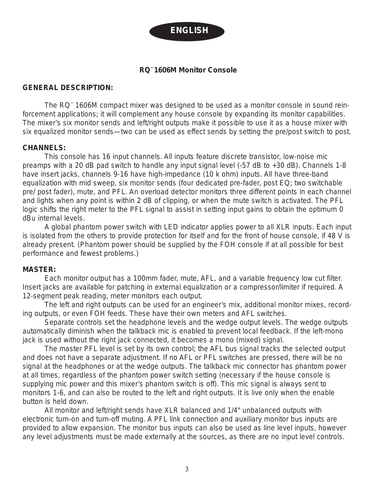
The RQ^ TM 1606M compact mixer was designed to be used as a monitor console in sound reinforcement applications; it will complement any house console by expanding its monitor capabilities. The mixer's six monitor sends and left/right outputs make it possible to use it as a house mixer with six equalized monitor sends—two can be used as effect sends by setting the pre/post switch to post.
CHANNELS:
This console has 16 input channels. All inputs feature discrete transistor, low-noise mic preamps with a 20 dB pad switch to handle any input signal level (-57 dB to +30 dB). Channels 1-8 have insert jacks, channels 9-16 have high-impedance (10 k ohm) inputs. All have three-band equalization with mid sweep, six monitor sends (four dedicated pre-fader, post EQ; two switchable pre/ post fader), mute, and PFL. An overload detector monitors three different points in each channel and lights when any point is within 2 dB of clipping, or when the mute switch is activated. The PFL logic shifts the right meter to the PFL signal to assist in setting input gains to obtain the optimum 0 dBu internal levels.
A global phantom power switch with LED indicator applies power to all XLR inputs. Each input is isolated from the others to provide protection for itself and for the front of house console, if 48V is already present. (Phantom power should be supplied by the FOH console if at all possible for best performance and fewest problems.)
MASTER:
Each monitor output has a 100mm fader, mute, AFL, and a variable frequency low cut filter. Insert jacks are available for patching in external equalization or a compressor/limiter if required. A 12-segment peak reading, meter monitors each output.
The left and right outputs can be used for an engineer's mix, additional monitor mixes, recording outputs, or even FOH feeds. These have their own meters and AFL switches.
Separate controls set the headphone levels and the wedge output levels. The wedge outputs automatically diminish when the talkback mic is enabled to prevent local feedback. If the left-mono jack is used without the right jack connected, it becomes a mono (mixed) signal.
The master PFL level is set by its own control; the AFL bus signal tracks the selected output and does not have a separate adjustment. If no AFL or PFL switches are pressed, there will be no signal at the headphones or at the wedge outputs. The talkback mic connector has phantom power at all times, regardless of the phantom power switch setting (necessary if the house console is supplying mic power and this mixer's phantom switch is off). This mic signal is always sent to monitors 1-6, and can also be routed to the left and right outputs. It is live only when the enable button is held down.
All monitor and left/right sends have XLR balanced and 1/4" unbalanced outputs with electronic turn-on and turn-off muting. A PFL link connection and auxiliary monitor bus inputs are provided to allow expansion. The monitor bus inputs can also be used as line level inputs, however any level adjustments must be made externally at the sources, as there are no input level controls.
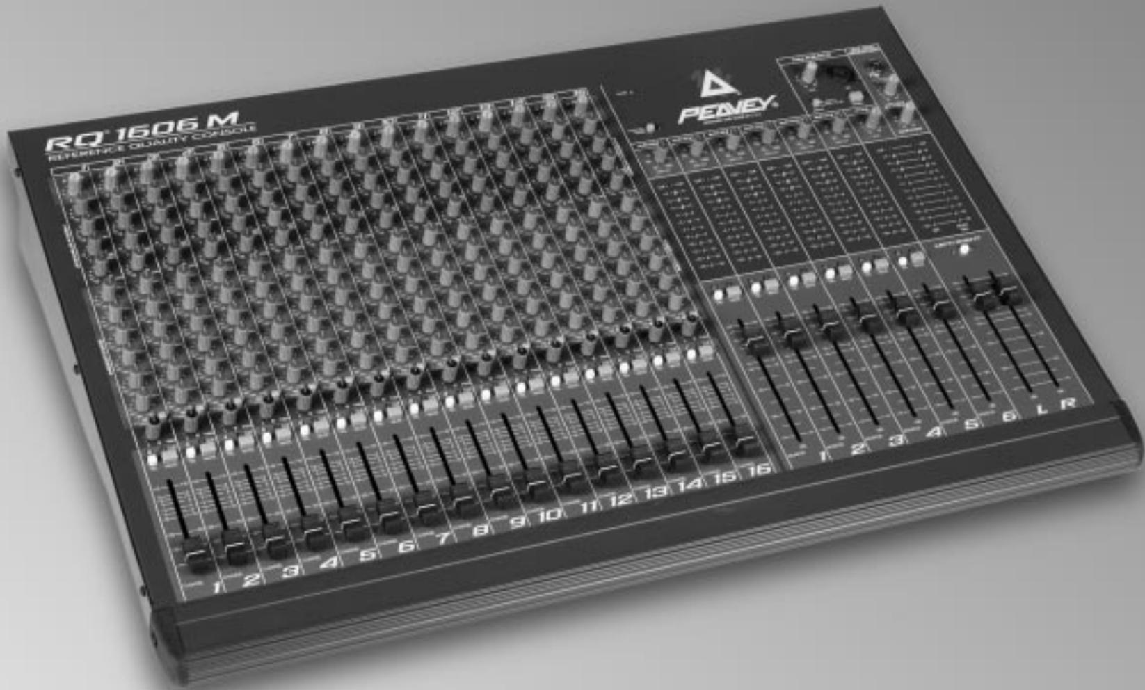
CHANNEL FUNCTIONS:
- FLS® (Feedback Locator System®) These LEDs illuminate to indicate the channel with the highest energy which is often the channel contributing to feedback. This function is pre-fader. (NOTE: These LEDs illuminate with any audio signal, not just during feedback.)
- GAIN: Varies the input gain to allow for a wide dynamic range. Proper adjustment of the input gain will maximize the signal-to-noise ratio. It should be set by depressing the PFL switch (#11) and adjusting it for a 0 dBu level at the L-R meters. At this point, there is 22 dB of headroom remaining. If clipping occurs at the minimum gain setting, engage the 20 dB pad (#31) located by the input jack.
- HI EQ: A shelving type of active tone control that varies the treble frequency levels ± 15 dB at 10kHz . It is designed to remove noise or to add brilliance to the signal, depending on the quality of the source.
- MID EQ: A bandpass (peak/notch) type of active tone control that varies the midrange frequency levels ± 15 dB. The frequency of the boost or cut is set by the mid frequency control (#5).
- MID FREQUENCY: Sets the frequency affected by the mid control (#4). The range is 100Hz to 3,000Hz .
- LOW EQ: A shelving type of active tone control that varies the bass frequency levels ± 15 dB at 70Hz . It will add depth to thin signals, or clean up muddy ones.
- MON(1-4): Adjusts the level of the channel signal (post-EQ, pre-fader) that is added to the monitor mix. The center detent is the unity gain (nominal) position.
- MON(5, 6): Adjusts the level of the channel signal (pre-fader, post-EQ, or post-fader) that is added to the monitor mix. The center detent is the unity gain (nominal) position.
- MON 5, 6 PRE/POST: Establishes which signal will be present on the mon 5 and 6 sends (#8). The out position picks up the signal after the tone equalization and before the channel fader (#14). The depressed position picks up the signal after the fader.
- PAN: Sets the channel's position in the left/right stereo field. It does not affect the monitor sends.
- PFL: Connects the channel's pre-fader (pre-mute) signal to the PFL mix and switches the headphone/wedge source from the AFL mix to the PFL mix. It also connects the PFL signal to the right meter to aid in the setting the input gain (#2). The PFL LED will light when this switch is pressed to identify the PFL source.
- MUTE: Mutes all channel signals except the PFL. The PFL signal is independent of this switch and can be used to check the channel and adjust its input gain even when the channel is muted.
- MUTE/CLIP LED: Normally indicates that the channel signal level is nearing the overload point. This circuit monitors the input gain, equalization, and post-fader stages for overload. It illuminates at +19 dBu and warns
that gain or EQ boost should be reduced. There is roughly 3 dB of headroom remaining when it lights. If the mute switch (#12) is depressed, it lights continuously to indicate that this channel has been muted.
- FADER: Left/right channel output level control. The level of the channel can be adjusted from off to +10 dB of gain. This slider also adjusts the relative level of monitors 5 and 6 if they are set to the post-fader signal. The optimum setting is the "0" (unity gain) position.
MASTER FUNCTIONS:
- PHANTOM POWER: Applies 48 V DC voltage to the input XLR connectors to power microphones that require it. This power is typically supplied by the house console, but if there is no other source, it is provided here. The circuitry is protected against voltage coming from the house console, but unusual phenomenons could occur if two mixers are used to supply power. The voltage of this console has been set slightly below the normal 48 V to allow it to auto-disconnect if another source is active.
If phantom power is used, do not connect unbalanced dynamic microphones or other devices that cannot handle this voltage to the XLR inputs, including the thru connector. This may damage some wireless receivers; consult their manuals for compatibility. The high-impedance input jacks on inputs 9-16 are not connected to the 48V supply and are safe for all inputs (balanced or unbalanced). An LED indicates that local phantom power is on.
CAUTION! When phantom power is switched on, make sure that any channel you are plugging a mic into is muted and all monitors and auxs are at minimum. Otherwise there will be a loud pop in the PA. This is normal. It is best to plug all mics into their respective channels with the phantom power switched off. This reduces noise in the PA and reduces the chances of the mic being damaged.
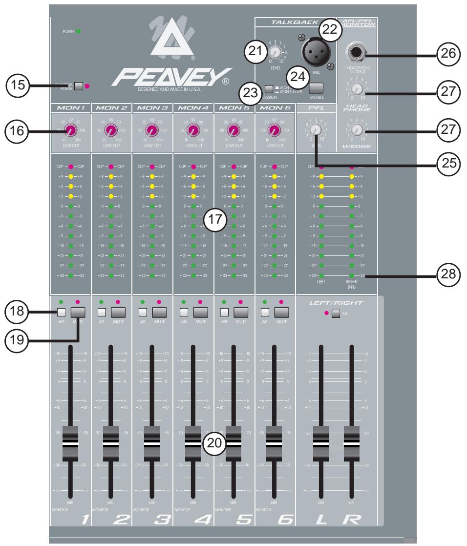
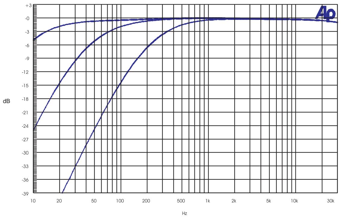
16. LOW CUT: A low cut filter with an adjustable corner frequency (10 to 300Hz ). It is used to filter out rumble, wind noise, breath thumps, stage noise, and other low frequency components that rob power from the amplifiers and muddy the signal. To disable the filter, set it at the minimum frequency setting.
17. LED METER ARRAY: A 12-segment peak reading LED array monitors the level of the corresponding output. The 0 dB reference level corresponds to 0 dBu at the 1/4 'acks (+4 dBu at the XLR jacks). The right meter array is also used for PFL, and displays the level of the PFL mix when any PFL switch is pressed.
18. AFL: Connects the channel's output signal (post fader) to the AFL mix. This mix is the default headphone and wedge mix. Its LED will light when this switch is pressed to identify which signals are included in the AFL mix. At least one source should be assigned, or there will be no headphone or wedge signal unless the PFL is active.
19. MONITOR MUTE: Mutes the monitor output. Its LED will light when muted.
20. MASTER FADER: Sets the overall level of the signal that is sent to the output jacks. The optimum setting for this control is the "0" (unity gain) position.
21. TALKBACK LEVEL: Sets the level of the talkback mic that is sent to monitors 1-6 and the left/right (if assigned). Engaged by the enable momentary switch.
22. TALKBACK MIC INPUT: low-impedance balanced mic input with phantom power (#15). Used to communicate with stage personnel or talent.
23. TALKBACK ASSIGN: The talkback signal is always sent to monitors 1-6. This switch adds a send to the left/right.
24. TALKBACK ENABLE: Engages the talkback mic while held down. The signal is routed through the talkback assign (#23) switch and controlled by the talkback level (#21).
25. PFL LEVEL: This control sets the level of the PFL mix that is sent to the headphones and the wedge outputs when the PFL is active. In normal operation, this control is adjusted to set the PFL level to match the AFL level.
26. HEADPHONE OUTPUT: This stereo jack TRS provides drive for the headphones. The level is set by the headphone level control. Tip=Left, Ring=Right, Shield=Ground.
27. HEADPHONE and WEDGE LEVELS: Independent adjustments of the headphone and wedge outputs. The source changes from the AFL mix to the PFL mix whenever the PFL is active. If no output is assigned to the AFL mix, there will be no signal present until a channel is assigned to the PFL mix. The wedge level will diminish (-20 dB) when the talkback mic is engaged to prevent feedback.
28. PFL ACTIVE: This LED flashes when the PFL is active and its signal is overriding the standard AFL mix in the headphone and wedge outputs and at the right meter. The signals that are present in the PFL mix can be seen by the individual PFL LEDs.
BACK PANEL
INPUT AND OUTPUT JACKS:
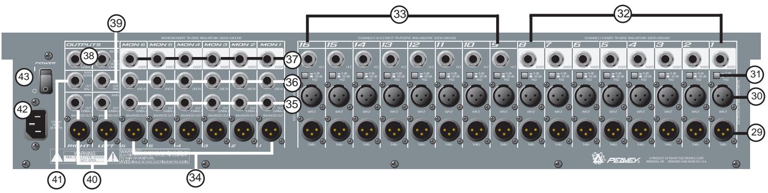
- THRU: This is a pass-through jack wired in parallel with the input jack (non-solated and has the same signal level). This jack also has the same phantom power that the other connector has, so use caution when connecting other equipment that could be damaged by 48 V DC. (#15)
- LOW-Z INPUT: XLR balanced input optimized for a microphone or other low-impedance source. Pin 2 is the positive input. Because of the wide range of gain adjustment, signal levels up to +32 dBu (with pad engaged) can be accommodated.
- PAD: Attenuates the input signal by 20 dB. This will increase the dynamic range to accommodate a higher input level before clipping, which may be necessary when close miking loud guitar amplifiers or drum kits. The high-impedance inputs (#33) are also affected.
- INSERT (CHANNEL 1-8): 14 stereo (TRS) jack which allows an external device (such as a compressor or graphic EQ) to be inserted into the signal path before the tone equalization. The tip has the send signal, the ring is the return input. A switch in the jack normally connects the send to the return until a plug is inserted. By inserting a jack only to the first click (so that the internal switch is not engaged), a preamp direct output is available without affecting the channel's normal operation.
- HI-Z INPUT (CHANNEL 9-16): 14 " balanced (TRS) high-impedance input. The tip is the positive input, which should also be used for unbalanced inputs. This input is connected to the mic input (#30) and changes the circuit's input impedance (including the XLR) when a jack is connected. It has the same gain as the XLR input, but does not have phantom power available. The two inputs cannot be used simultaneously.
- MONITOR OUT (XLR): Balanced output of the monitor mix designed to feed an external monitor amplifier (Pin 2 is positive). The output level is set by the individual channel monitor send controls and by the master monitor fader.
- MONITOR OUT (1/4"): Unbalanced output of the monitor mix.
- MONITOR LINE INPUT: This is a balanced (TRS) bus input to the corresponding monitor mix. It can be used to expand the mixer by connecting another source (mixer or other device) here to add to the monitor's mix. There are no controls for this jack (0 dBu nominal).
- MONITOR INSERT: 1/4" stereo (TRS) jack which allows an external device (such as a compressor or graphic EQ) to be inserted into the monitor's signal path. The tip has the send signal, the ring is the return input. A switch in the jack normally connects the send to the return until a plug is inserted.
-
WEDGE OUTPUTS: 1/4 unbalanced output to feed the wedge monitor amp. The signal is exactly the same as that in the headphones, but has other features. When the talkback mic is active, these outputs are diminished to prevent local feedback. If there is no plug connected into the right output jack, the left and right wedge signals are summed to mono. Wedge levels are set by the wedge control, and are independent from the headphone levels.
-
PFL LINK: This is a port that makes it possible to parallel two RQ 1606M mixers, increasing the number of inputs. A shielded stereo (TRS) cord connected between them will cause the two mixer's PFL circuits to merge. Then any PFL switch pressed will take over the right meter of the unit supplying the signal and change the headphone/wedge source on both units.
- MAIN OUTPUTS: 1 / 4'' unbalanced and XLR balanced outputs of the left and right mixes. The output level is set by the master left and right faders. The XLR outputs are 4 dB higher in level than the 1 / 4'' outputs.
- MAIN MONO OUTPUT: 1/4" balanced (TRS) mono output representing a combination of the left and right signals.
- AC MAINS INPUT: Connect the line cord to this connector to provide power to the unit. Damage to the equipment may result if improper line voltage is used. Operate only with the specified AC input voltage applied. (See line voltage marking on unit.)
- POWER: The mixer's main power switch.
TYPICAL RQ™ 1606M HOOK-UPS:
MONITOR MIXER:
- Connect the low-impedance microphones (or the mic connectors from the snake cable) to the XLR inputs. Connect the thru outputs to the house console's mic inputs. If phantom power is required, use the power provided by the house console unless it is not available. This will provide the best performance and cause the fewest problems. If the RQ 1606M provides the phantom power, it will apply 48V to all the XLR inputs which may not be desired at the other console.
- High-impedance inputs (synth, CD, tape, etc.) should be connected to the 1/4'' Hi-Z inputs on channels 9-16. These are balanced (TRS) and have the same gain as the XLR inputs. High level signals will require activation of the 20 dB pad switch located by the jack to avoid clipping.
- Processors (EQ, delay, or compression) can be connected into the channel 1-8 inserts or to the monitor 1-6 inserts.
- Connect the monitor power amp inputs to the monitor outputs. Both balanced and unbalanced outputs are provided and can be used simultaneously.
- Connect the engineer's mix (wedge) power amps to the wedge outputs. This is the same signal that is at the headphones (AFL or PFL, depending on the switch settings).
- Recording equipment or other feeds can be connected to the left/right outputs. Monitors 5 and 6 can be set post fader and can also be used for specialized outputs where fader control is desired.
- To slave additional monitor mixers, connect the PFL links together (parallel wired) and patch the slave's monitor outputs to the master monitor's line inputs and set the output levels on the slave to match those on the master. Either console's PFL signal will take over the wedge and headphone outputs of both mixers.
- Connect the low-impedance microphones to the XLR inputs. Any mic that requires an external effect processor or compressor should be connected to one of the first eight inputs which have insert jacks.
- High-impedance inputs (synth, CD, tape, etc.) should be connected to the 1/4'' Hi-Z inputs on channels 9-16. These are balanced (TRS) and have the same gain as the XLR inputs, but do not have phantom power available. High level signals will require activation of the 20 dB pad switch (located by the jack) to avoid clipping.
- Connect the monitor power amp inputs to the monitor outputs. Both balanced and unbalanced outputs are provided and can be used simultaneously.
- The house power amp inputs connect to the left/right (or the mono) outputs.
- If effects are desired, set monitor 5 and 6 sends to post fader and route these monitor outputs to the effect device's inputs. The effect return signal must be brought back into the monitor's line input or into the mixer using unused input channels (9-16 have Hi-Z inputs). Do not turn up the monitor 5 or 6 sends on these channels or feedback will result. Local monitoring can be done with either headphones or the wedge outputs.
RQ™ 1606M LEVELS DIAGRAM
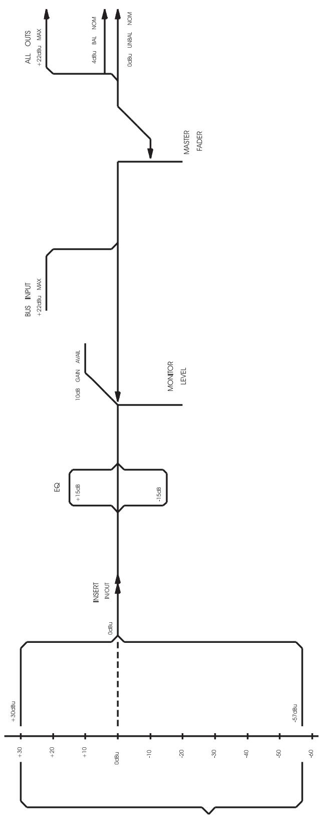
CHANNEL
INPUTS
(INCLUDES PAD)
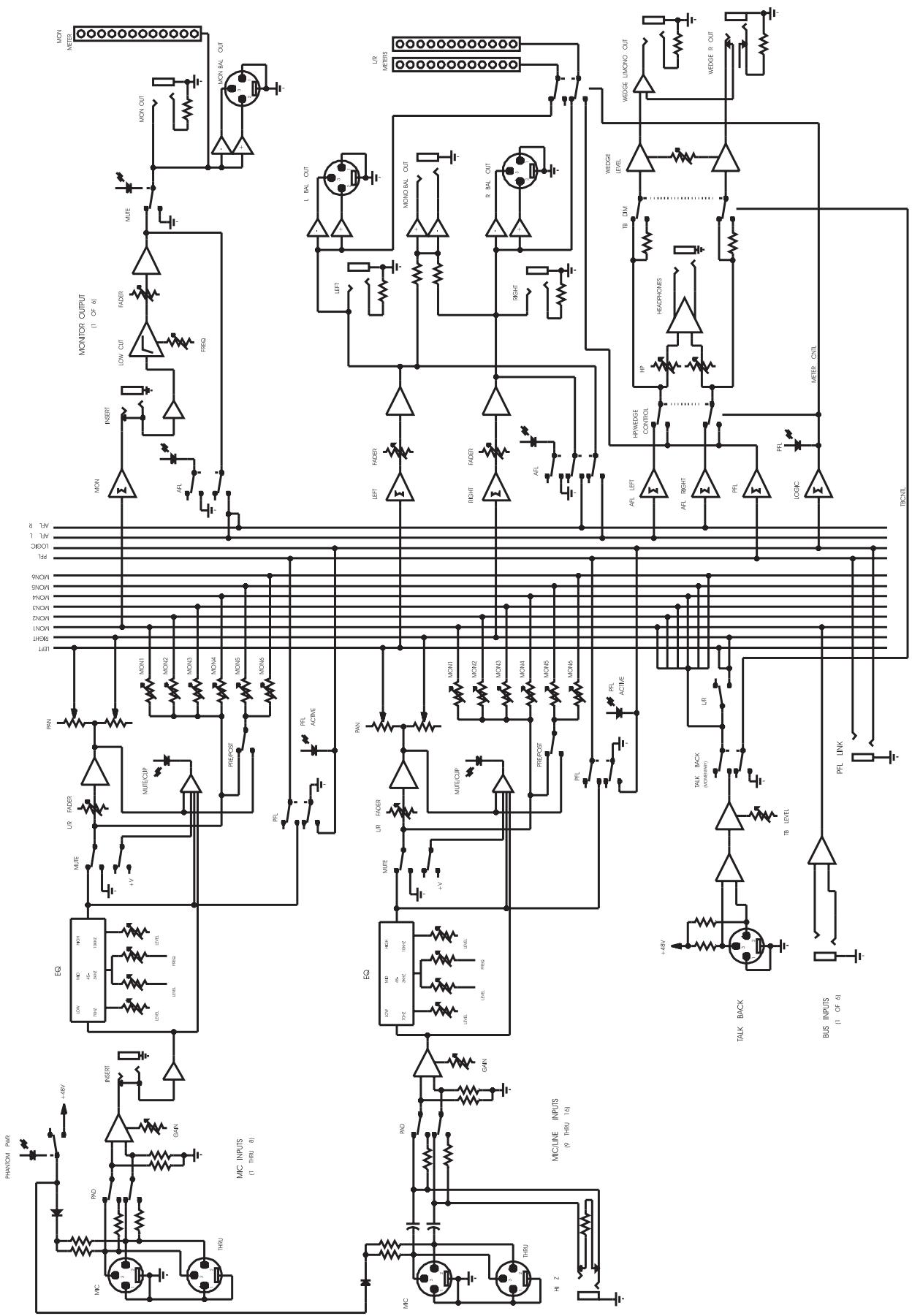
RQ™ 1606M BLOCK DIAGRAM
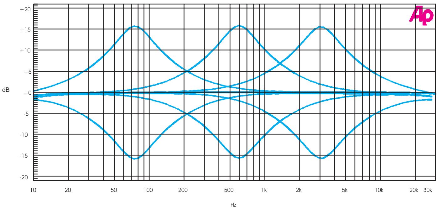
RQ™ 1606M MID SWEEP
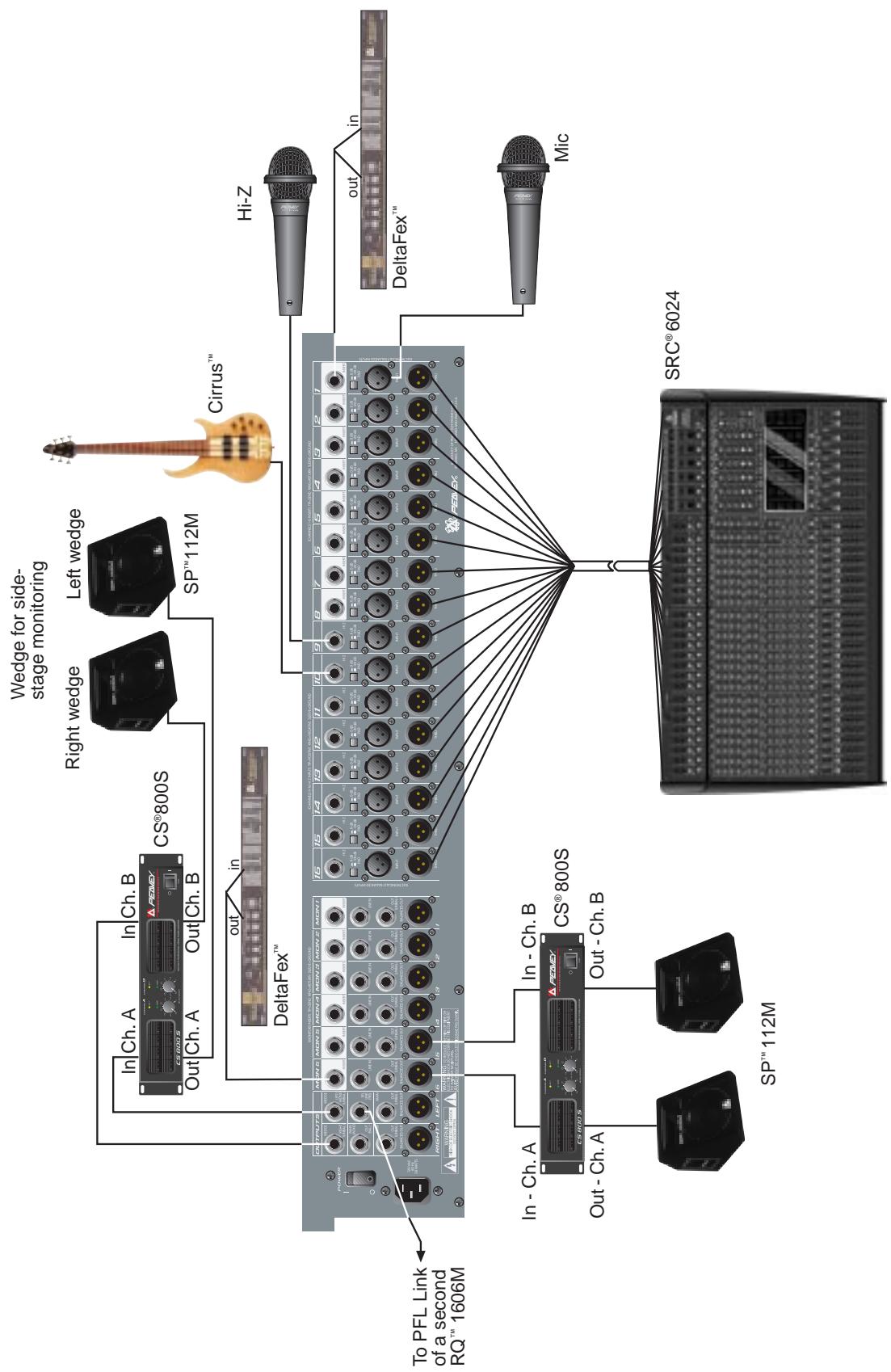
RQ™ 1606M HOOK-UP DIAGRAM
RQ® 1606M Monitor Console
Specifications:
Input Specifications:
| Function | Input z (ohms) Min | Input Gains Setting | Input Levels^ | Bal./ UnBal. | Connector | ||
| Min** | Nominal* | Max | |||||
| XLR Input (150 ohms) | 2.2 k | Max gain (57 dB) | -77 dBu | -57 dBu | -35 dBu | Bal. | XLR: Pin 1 Gnd Pin 2 (+), Pin 3 (-) |
| Min. gain (10 dB) | -30 dBu | -10 dBu | +12 dBu | ||||
| Hi-Z (10 k ohms) | 10 k | Max. gain (57 dB) | -77 dBu | -57 dBu | -35 dBu | Bal. | 1/4" TRS: Tip (+), Ring (-), Sleeve Ground |
| Min. gain (10 dB) | -30 dBu | -10 dBu | +12 dBu | ||||
| Insert Return | 22 k | N/A (0 dB) | -20 dBu | 0 dBu | +22 dBu | Unbal. | 1/4" TRS: Tip Send, Ring Return, Sleeve Ground |
| Monitor Aux Input | 10 k | N/A (0 dB) | -20 dBu | 0 dBu | +21 dBu | Ba.I | 1/4" TRS: Tip (+), Ring (-), Sleeve Ground |
| Talkback Mic | 2.2 k | N/A (30 dB) | -54 dBu | -30 dBu | -8 dBu | Bal. | XLR: Pin 1 Gnd Pin 2 (+), Pin 3 (-) |
0 dBV=1V (RMS)
* Min input level (sensitivity) is the smallest signal that will produce nominal output (0 dBu) with channel and master level controls set for maximum gain.
Nominal settings are defined as all controls set at 0 dB (or 50% rotation for rotary pots) except the gain adjustment pot, which is as specified.
^ Input 20 dB pad is not included in these levels.
RQ™ 1606M Output Specifications:
| Function | Minimum Load Z (Ohms) | Output Level | Bal./Unbal. | Connector | |
| Nominal | Max. | ||||
| Main L/R Monitor | 600 | 0 dBu | +22 dBu | Unbal. | 1/4" Phono |
| +4 dBu | +26 dBu | Bal | XLR: Pin 1 Gnd, Pin 2 (+), Pin 3 (-) (Bal) | ||
| Channel Insert Send | 600 | 0 dBu | +22 dBu | Unbal. | 1/4" TRS: Tip Send, Ring Return, Sleeve Ground |
| Wedge | 600 | 0 dBu | +22 dBu | Unbal. | 1/4" Phone |
| Headphone | 8 | 0 dBu(no load) | +22 dBu | Unbal. | 1/4" TRS: Tip Left, Ring Right, Sleeve Ground |
0dBu = 0.775V (RMS)
RQ™ 1606M Hum and Noise:
| Output | Residual Noise | S/N Ratio Ref: 0 dBu | Test Conditions |
| Monitor | -97 dBu | 97 dB | All faders down |
| -90 dBu | 90 dB | Master fader nominal, All channels muted | |
| -84 dBu | 84 dB | All controls nominal, mic gain min | |
| Left/Right | -97 dBu | 97 dB | All fader down |
| -90 dBu | 90 dB | Master gader nominal, Channel faders down, All channels muted | |
| -84dBu | -84 dB | All controls nominal, mic gain min | |
(Hum and Noise Measurements: 22 Hz to 22 kHz BW)
RQ™ 1606M Specifications:
Gain:
Input gain adj. range: -10 dB to 57 dB (includes pad)
Input to any bal. output: 81 dB (max. gain)
Monitor Aux in to monitor bal. output: 10 dB (max. gain)
Frequency Response:
Mic Input to L-R output: 20 Hz to 64 kHz + 0 dB / -1 dB
Total Harmonic Distortion (THD):
<0.003% 20 Hz to 20 kHz Mic to L-R output: (10 Hz to 80 kHz BW)
Equivalent Input Noise (EIN):
-129 dBu (Input terminated with 150 ohms)
Crosstalk:
80 dB adjacent input channels: (20 Hz to 20 kHz)
70 dB left and right outputs: (20 Hz to 20 kHz)
Common Mode Rejection Ration (Mic Input):
60 dB min (20 Hz to 20 kHz)
70 dB type @ 1 kHz
Meters:
12 segment, peak reading.
(0dB = 9dBu)
Signal/Overload Indicators:
Red LED lights 3 dB below clipping
Dimensions: (H x W x D)
5.375" x 27.875" x 18.875"
Weight:
23 pounds
Power Requirements:
DOM: 120 V AC 60 Hz 38 Watts Nominal
EXP: 230 V AC 50/60 Hz 38 Watts Nominal
Consola de Monitoreo RQ™ 1606M
Purchaser and is subject to the conditions, exclusions, and limitations hereinafter set forth:
PEAVEY 90-DAY LIMITED WARRANTY ON TUBES AND METERS
If this product contains tubes or meters, Peavey warrants the tubes or meters contained in the product to be free from defects in material and workmanship for a period of ninety (90) days from date of purchase; PROVIDED, however, that this limited warranty is extended only to the original retail purchaser and is also subject to the conditions, exclusions, and limitations hereinafter set forth.
CONDITIONS, EXCLUSIONS, AND LIMITATIONS OF LIMITED WARRANTYES
These limited warranties shall be void and of no effect, if:
a. The first purchase of the product is for the purpose of resale; or
b. The original retail purchase is not made from an AUTHORIZED PEAVEY DEALER; or
c. The product has been damaged by accident or unreasonable use, neglect, improper service or maintenance, or other causes not arising out of defects in material or workmanship; or
d. The serial number affixed to the product is altered, defaced, or removed.
In the event of a defect in material and/or workmanship covered by this limited warranty, Peavey will:
a. In the case of tubes or meters, replace the defective component without charge.
b. In other covered cases (i.e., cases involving anything other than covers, footswitches, patchcords, tubes or meters), repair the defect in material or workmanship or replace
the product, at Peavey's option; and provided, however, that, in any case, all costs of shipping, if necessary, are paid by you, the purchaser.
THE WARRANTY REGISTRATION CARD SHOULD BE ACCURATELY COMPLETED AND MAILED TO AND RECEIVED BY PEAVEY WITHIN FOURTEEN (14) DAYS FROM THE DATE OF YOUR PURCHASE.
In order to obtain service under these warranties, you must:
a. Bring the defective item to any PEAVEY AUTHIZED DEALER or AUTHORIZED PEAVEY SERVICE CENTER and present therewith the ORIGINAL
PROOF OF PURCHASE supplied to you by the AUTHORIZED PEAVEY DEALER in connection with your purchase from him of this product
If the DEALER or SERVICE CENTER is unable to provide the necessary warranty service you will be directed to the nearest other PEAVEY AUTHORIZED
DEALER or AUTHORIZED PEAVEY SERVICE CENTER which can provide such service, OR
b. Ship the defective item, prepaid, to:
PEAVEY ELECTRONICS CORPORATION
International Service Center
326 Hwy. 11 & 80 East
Meridian, MS 39301
Including therewith a complete, detailed description of the problem, together with a legible copy of the original PROOF OF PURCHASE and a complete return
address. Upon Peavey's receipt of these items: If the defect is remedial under these limited warranties and the other terms and conditions expressed herein
have been complied with, Peavey will provide the necessary warranty service to repair or replace the product and will return it, FREIGHT COLLECT, to you,
the purchaser.
Peavey's liability to the purchaser for damages from any cause whatsoever and regardless of the form of action, including negligence, is limited to the actual damages up to the greater of (500.00 or an amount equal to the purchase price of the product that caused the damage or that is the subject of or is directly related to the cause of action. Such purchase price will be that in effect for the specific product when the cause of action arose. This limitation of liability will not apply to claims for personal injury or damage to real property or tangible personal property allegedly caused by Peavey's negligence, Peavey does not assume liability for personal injury or property damage arising out of or caused by a non-Peavey alteration or attachment, nor does Peavey assume any responsibility for damage to interconnected non-Peavey equipment that may result from the normal functioning and maintenance of the Peavey equipment.
UNDER NO CIRCUMSTANCES WILL PEAVEY BE LIABLE FOR ANY LOST PROFITS, LOST SAVINGS, ANY INCIDENTAL DAMAGES, OR ANY
CONSEQUENTIAL DAMAGES ARISING OUT OF THE USE OR INABILITY TO USE THE PRODUCT, EVEN IF PEAVEY HAS BEEN ADVISED OF THE POSSIBILITY
OF SUCHDMAGES
THESE LIMITED WARRANTY ARE IN LIEU OF ANY AND ALL WARRANTYES, EXPRESSED OR IMPLIED, INCLUDING, BUT NOT LIMITED TO, THE IMPLIED WAR
RANTIES OF MERCHANTABILITY AND FITNESS FOR A PARTICULAR USE: PROVIDED, HOWEVER, THAT IF THE OTHER TERMS AND CONDITIONS NECESSARY TO THE EXIS
TENCE OF THE EXPRESSED, LIMITED WARRANTYES, AS HEREINABOVE STATED, HAVE BEEN COMPLIED WITH, IMplied
WARRANTIES ARE NOT DISCLAIMED DURING THE APPLICABLE ONE-YEAR OR NINETY-DAY PERIOD FROM DATE OF PURCHASE OF THIS PRODUCT.
SOME STATES DO NOT ALLOW LIMITATION ON HOW LONG AN IMPLIED WARRANTY LASTS, OR THE EXCLUSION OR LIMITATION OF INCIDENTAL
OR CONSEQUENTIAL DAMAGES. SO THE ABOVE LIMITATIONS OR EXCLUSIONS MAY NOT APPLY TO YOU. THESE LIMITED WARRANTYES GIVE YOU SPECIFIC LEGAL
RIGHTS, AND YOU MAY ALSO HAVE OTHER RIGHTS WHICH MAY VARY FROM STATE TO STATE.
THESE LIMITED WARRANTYES ARE THE ONLY EXPRESSED WARRANTYES ON THIS PRODUCT, AND NO OTHER STATEMENT, REPRESENTATION, WARRANTY, OR
AGREEMENT BY ANY PERSON SHALL BE VALID OR BINDING UPON PEAVEY.
In the event of any modification or disclaimer of expressed or implied warranties, or any limitation of remedies, contained herein conflicts with applicable law, then such modification, disclaimer or limitation, as the case may be, shall be deemed to be modified to the extent necessary to comply with such law.
Your remedies for breach of these warranties are limited to those remedies provided herein and Peavey Electronics Corporation gives this limited warranty only with respect to equipment purchased in the United States of America.
INSTRUCTIONS—WARRANTY REGISTRATION CARD
- Mail the completed WARRANTY REGISTRATION CARD to:
PEAVEY ELECTRONICS CORPORATION
P.O. BOX 2898
Meridian, MS 39302-2898
a. Keep the PROOF OF PURCHASE In the event warranty service is required during the warranty period, you will need this document. There will be no identification card issued by Peavey Electronics Corporation
- IMPORTANCE OF WARRANTY REGISTRATION CARDS AND NOTIFICATION OF CHANGES OF ADDRESSES:
a. Completion and mailing of WARRANTY REGISTRATION CARDS—Should notification become necessary for any condition that may require correction the REGISTRATION CARD will help ensure that you are contacted and properly notified.
b. Notice of address changes - If you move from the address shown on the WARRANTY REGISTRATION CARD, you should notify Peavey of the change of address so as to facili-
tate your receipt of any bulletins or other forms of notification which may become necessary in connection with any condition that may require dissemination of information or correction.
- You may contact Peavey directly by telephoning (601) 483-5365.
IMPORTANT SAFETY INSTRUCTIONS
WARNING: When using electric products, basic cautions should always be followed. including the following.
- Read all safety and operating instructions before using this product.
- All safety and operating instructions should be retained for future reference.
- Obey all cautions in the operating instructions and on the back of the unit.
- All operating instructions should be followed.
- This product should not be used near water, i.e., a bathtub, sink, swimming pool, wet basement, etc.
- This product should be located so that its position does not interfere with its proper ventilation. It should not be placed flat against a wall or placed in a built-in enclosure that will impede the flow of cooling air.
- This product should not be placed near a source of heat such as a stove, radiator, or another heat producing amplifier.
- Connect only to a power supply of the type marked on the unit adJacent to the power supply cord.
- Never break off the ground pin on the power supply cord. For more information on grounding, write for our free booklet "Shock Hazard and Grounding."
- Power supply cords should always be handled carefully. Never walk or place equipment on power supply cords. Periodically check cords for cuts or signs of stress, especially at the plug and the point where the cord exits the unit.
11 The power supply cord should be unplugged when the unit is to be unused for long periods of time. - If this product is to be mounted in an equipment rack, rear support should be provided.
- Metal parts can be cleaned with a damp rag. The vinyl covering used on some units can be cleaned with a damp rag or an ammonia-based household cleaner if necessary. Disconnect unit from power supply before cleaning.
- Care should be taken so that objects do not fall and liquids are not spilled into the unit through the ventilation holes or any other openings.
- This unit should be checked by a qualified service technician if:
a. The power supply cord or plug has been damaged.
b. Anything has fallen or been spilled into the unit.
c. The unit does not operate correctly.
d. The unit has been dropped or the enclosure damaged.
- The user should not attempt to service this equipment. All service work should be done by a qualified service technician.
- This product should be used only with a cart or stand that is recommended by Peavey Electronics.
- Exposure to extremely high noise levels may cause a permanent hearing loss. individuals vary considerably in susceptibility to noise induced hearing loss, but nearly everyone will lose some hearing if exposed to sufficiently intense noise for a sufficient time. The U.S. Government's Occupational Safety and Health Administration (OSHA) has specified the following permissible noise level exposures.
Duration Per Day In Hours
8
6
4
3
2
1.1/2
1
1/2
1/4 or less
Sound Level dBA, Slow Response
90
92
95
97
100
102
105
110
115
According to OSHA, any exposure in excess of the above permissible limits could result in some hearing loss. Ear plugs or protectors h1 the ear canal]s or over the ears must be worn when operating this amplification system in order to prevent a permanent hearing loss if exposure is in excess of the limits as set forth above. To ensure against potentially dangerous exposure to high Sound pressure levels, it is recommended that all persons exposed to equipment capable of producing high sound pressure levels such as this amplification system be protected by hearing protectors while this unit is in operation.
SAVE THESE INSTRUCTIONS!


Features and specifications subject to change without notice.
Peavey Electronics Corporation • 711 A Street • Meridian • MS • 39301 • (601) 483-5365 • FAX 486-1278