Energy Station FP - Battery charger GYS - Free user manual and instructions
Find the device manual for free Energy Station FP GYS in PDF.

User questions about Energy Station FP GYS
0 question about this device. Answer the ones you know or ask your own.
Ask a new question about this device
Download the instructions for your Battery charger in PDF format for free! Find your manual Energy Station FP - GYS and take your electronic device back in hand. On this page are published all the documents necessary for the use of your device. Energy Station FP by GYS.
USER MANUAL Energy Station FP GYS
natural_image
Line drawing of a mechanical cart with wheels and a top panel (no text or symbols)| FR | 02-04 / 05-11 / 54-60 |
| EN | 02-04 / 12-18 / 54-60 |
| DE | 02-04 / 19-25 / 54-60 |
| ES | 02-04 / 26-32 / 54-60 |
| RU | 02-04 / 33-39 / 54-60 |
| NL | 02-04 / 40-46 / 54-60 |
| IT | 02-04 / 47-53 / 54-60 |
ENERGY STATION FP
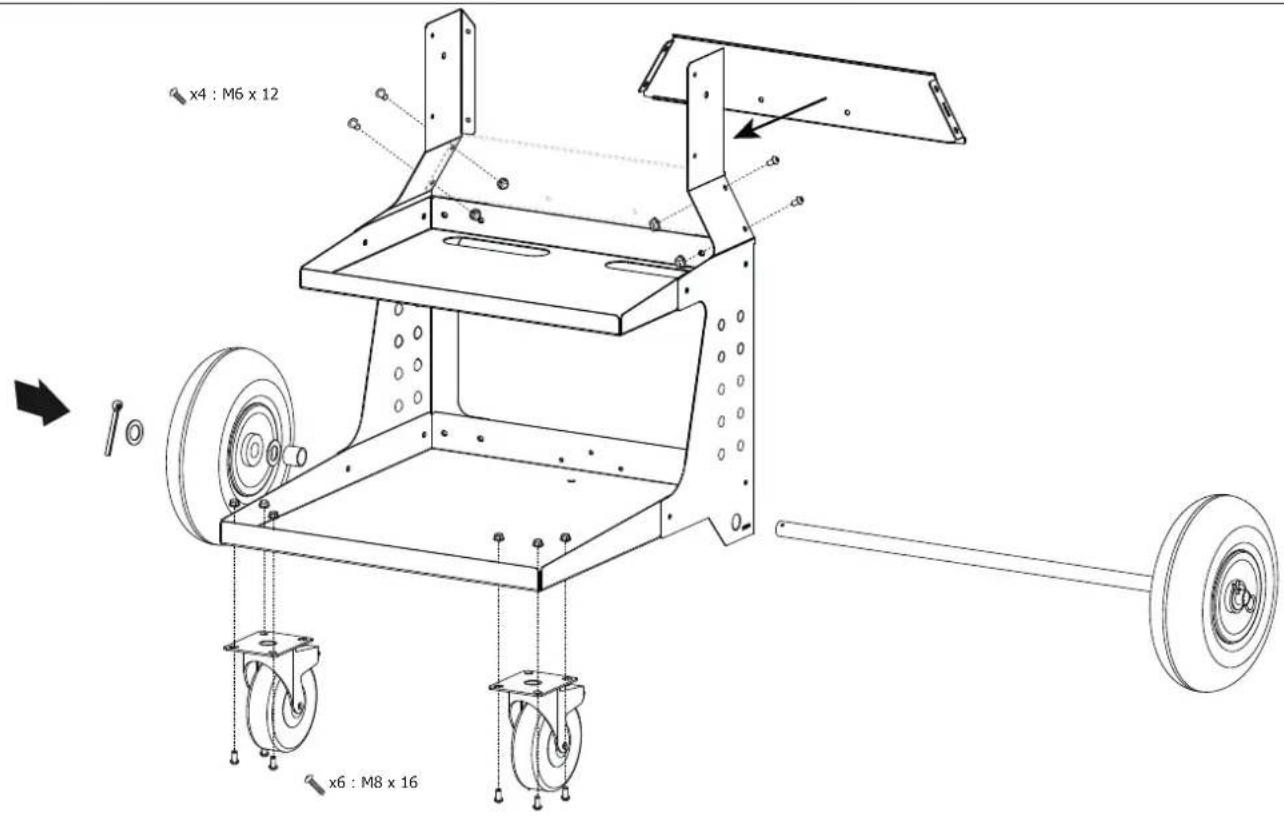
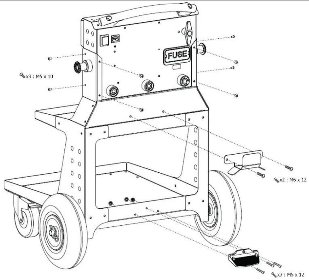
MONTAGE CHARIOT / ASSEMBLING THE TROLLEY / MONTAGE WAGEN / МОНТАЖ ТЕЛЕЖКИ / MON- TAGE TROLLEY / MONTAGGIO CARRELLO
Tableau récapitulatif / Summary table / Zusammenfassende Tabelle / Сводная таблица / Overzichtstabel / Tabella ricapitolativa
| Dimensions Quantity Reference | ||
 | M5 x 10 x 8 41025 | |
 | M5 x 12 x 3 42024 | |
 | M6 x 12 x 22 41276 | |
 | M8 x 16 x 6 41017 | |
 | M6 x 50 x 2 41287 | |
 | M5 x 3 41154 | |
 | M6 x 22 41151 | |
 | M8 x 6 41157 | |
| [wezel] | M6 x 2 41204 | |
| [freed] | M20 x 4 41214 | |
 | - x 2 42032 | |
 | M20 x 2 90917 | |
 | - x 1 56077 | |
 | - x 2 56037 | |
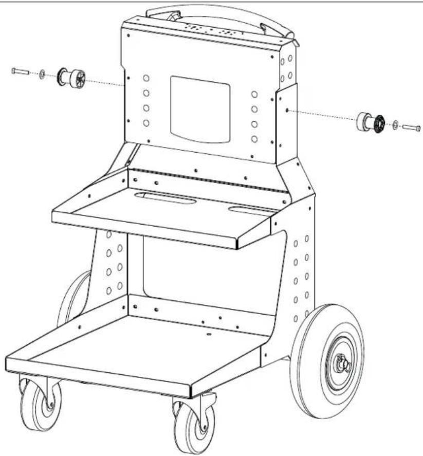
1

natural_image
Technical line drawing of a mechanical assembly with mounting brackets and structural features (no text or symbols)2

x6 : M8 x 16

x6: M8

x4 : M6 x 12

x4: M6

x2

x4 : M20

x2
3
|

x2 : M6 x 50

x2 : M6
x2
natural_image
Technical line drawing of a mechanical cart with wheels and mounting holes (no text or symbols)4

x8 : M5 x 10

x3 : M5 x 12

x3 : M5
x 1

x2 : M6 x 12

x2 : M6
natural_image
Technical line drawing of a vehicle chassis with wheels and control panel (no text or symbols)natural_image
Technical line drawing of a mechanical device with wheels and control panel (no text or symbols)line
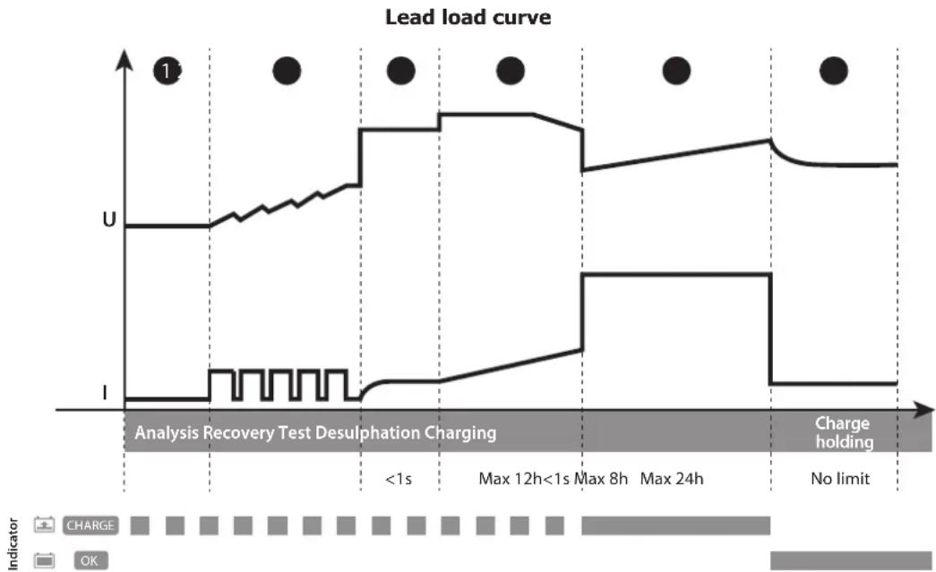
| Time Interval | Voltage (U) | Current (I) | | ------------- | ----------- | ----------- | | <1s | High | Low | | Max 12h | High | Low | | Max 8h | High | Low | | Max 24h | High | Low | | No limit | Low | Low |Étape 1 : Analyse
ANALYSES, CAUSES, REMÈDES
CONDITIONS DE GARANTIE
This user manual includes information on how to operate the appliance and the safety precautions to be followed. Please read it carefully before first use and keep it for future reference. These instructions must be read and fully understood before any operations are performed. Do not undertake any modifications or maintenance work that is not explicitly stated in this user manual. The manufacturer cannot be held responsible for any bodily injury or material damage resulting from use that does not comply with the instructions in this manual. If you have any problems or queries, consult a qualified person to operate the appliance correctly. This equipment should only be used for recharging and/or starting vehicles within the limits indicated on the appliance and in this manual. These safety instructions must be followed. The manufacturer cannot be held responsible if the machine is used improperly or dangerously.
This machine may be used by children aged at least eight years old as well as by people with reduced physical, sensory or mental capabilities or by those lacking relevant experience or knowledge. However, this is only permitted if these people are properly supervised or if they have been given suitable instructions in order to safely operate the machine. Also, the risks involved must have been explained and properly understood. Children must not play with the device. Cleaning and maintenance work must not be carried out by children unless they are supervised.
Under no circumstances should be used to charge non-rechargeable batteries.
Only use the charger supplied with the device to recharge the batteries.
Do not use the device if the power lead or mains plug is damaged.
To avoid any risk of short-circuiting the battery, do not use this equipment if the charger is damaged or has an assembly fault. Never charge a frozen or damaged battery.
Do not cover this device.
Do not position the appliance near a heat source or anywhere with permanently high temperatures (above 60^ C).
The automatic operating mode and usage restrictions are explained further in this manual.
Risk of explosion or acid projection in case of short-circuit of the clamps or if the 12V booster is connected to a 24V vehicle or vice versa.


Risk of explosion and fire!
A charging battery can emit explosive gases.
- During charging, the battery should be placed in a well-ventilated location.
- Avoid flames and sparks. Do not smoke.
- Protect the batteries' electrical contact surfaces against short circuits.
- Do not leave a charging battery unattended for long periods of time.


Risk of acid spatter!
- Wear protective goggles and gloves.
- If contact occurs with the eyes or skin, rinse immediately with water and seek medical advice.
Login / Logout:
- Disconnect the power supply before connecting or disconnecting the battery.
- The battery terminal that is not connected to the chassis must be connected first. The other connection should be made on the chassis away from the battery and fuel line.
- After the start-up operation, disconnect the booster. First remove the chassis connection and then the battery connection, in the order shown.

Connection:
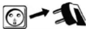
- This appliance must be connected to an earthed socket outlet.
- Connecting to the mains supply must be done in accordance with national installation regulations.
Maintenance:
- If the power supply cable is damaged, it must only be replaced by a cable specified or supplied by the manufacturer or its after-sales service.
- Maintenance work should only be carried out by qualified persons.
- Warning! Always remove the plug from the mains socket before carrying out any work on this equipment.
- Regularly remove the machine's protective cover and dust with compressed-air. Take this opportunity to have a qualified person check the electrical connections with an insulated tool.
- Never use solvents or other aggressive cleaning products.
- Clean the machine's surfaces with a dry cloth.

Regulations:
- This device complies with European directives.
- The declaration of conformity is available on our website.
• EAC (Eurasian Economic Community) conformity mark.
• This equipment conforms to UK standards.
The UK Declaration of Conformity is available on our website (see front cover).
• This equipment conforms to Moroccan standards.
The C _o (CMIM) Declaration of Conformity is available on our website.
Disposal:
- This machine is subject to selective-collection regulations. Do not dispose of this appliance in your domestic waste.
- The device must be disconnected from the mains supply before removing the battery.
GENERAL DESCRIPTION
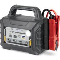
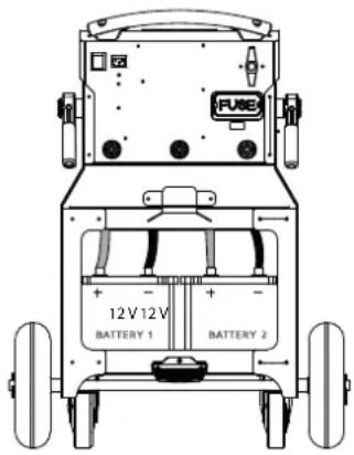
The ENERGY STATION FP is an autonomous starter (supplied without batteries) designed specifically for starting vehicles fitted with a 12 - 24 V battery. This trolley can be used to set up one or two 12 V batteries (6 x 2 V cells) with a capacity of up to 375 Ah each.
The appliance includes a 12 V / 30 A battery charger to charge the lead batteries present on the trolley (alternately) as well as to charge an external battery. It also has a battery testing function.
To guarantee the correct functioning of the equipment and to preserve the life of the batteries on the trolley, it is imperative to connect the ENERGY STATION FP to the mains supply after each use.
INTERNAL BATTERIES AND CHARGING CLAMPS
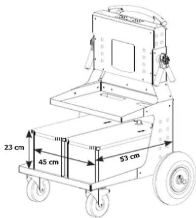
Two 'internal' batteries (not included) must be fitted before using the unit: 12 V, lead-acid batteries with a capacity of 100 - 375 Ah each. Their size should not exceed 45 x 53 x 23 cm and the total max. weight is 100 kg.
To install them:
- Disconnect the power lead or set the ON/OFF switch to the '0' position.
- Attach the four supplied battery terminals to the four cables.
- Connect the batteries to the ENERGY STATION FP ensuring correct polarity:
- the red cable to the positive (+) battery terminal
- the black cable to the negative (-) battery terminal
BATTERY TEST

- Unplug the power cable or set the ON/OFF switch to 'OFF'.


- Press the test button (test one or two batteries depending on the batteries connected).
- Green indicator light: battery charged (> 12.8 V). Start-up is possible.
- Orange indicator light: battery is partially charged (voltage between 12.4 -12.8 V). We strongly recommend recharging the batteries before using the machine. However, it is possible to start a vehicle.
- Red indicator light: battery is discharged (voltage < 12.4V ). Unable to start.
- No indicator light: Battery very deeply discharged or no battery is detected (< 4 V). Unable to start.

The test is only valid if the battery (or batteries) has been idle for at least 15 minutes.
STARTER FUNCTION
12 V Mode
natural_image
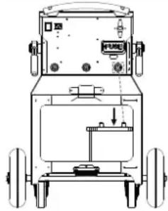
Technical line drawing of a mechanical device with wheels and a labeled component (no text or symbols present)For starting with 12 V, only one battery can be fitted to the trolley. In this case, the one battery must be positioned on the right side (when viewed from behind) in order to be connected to the device's negative (-) terminal.


- Unplug the mains lead (battery charged beforehand).
- Set the battery switch to the 'OFF' position.
- Connect the cables to the ENERGY STATION FP's 12 V output (red cable to the 12 V outlet, black cable to the battery's negative [-] terminal).
- Connect the red clamp to the battery's positive (+) terminal and the black clamp to the negative (-) terminal (if the polarity is reversed, this will be indicated by the Energy Station; a warning buzzer will sound and the red LED indicator light will light up 🔊️ △ ⚫️).
- Switch the battery switch to the 'ON' position.


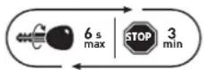
- Go to the vehicle control station and turn the ignition key. If the engine will not start, wait three minutes between each start-up attempt (each start-up attempt should last no longer than six seconds max.).
- If the recommended time between each test is not respected (3 minutes) or if the test time is too long (> 6 seconds), the likelihood of starting the vehicle is reduced (risk of power loss).
- There is a risk of acid leakage and damage to the internal battery if the recommended times are not observed.
- If the vehicle still does not start, there may be a problem other than a bad battery: a faulty alternator or glow plug, etc.

- Switch the battery switch to the 'OFF' position.
- Recharge the batteries after use (see charger section).
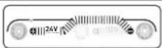
24 V mode
natural_image
Technical line drawing of a mechanical device with wheels and control panel (no text or symbols)To start in 24 V mode, two 12 V batteries must be fitted to the trolley.


- Unplug the mains lead (batteries charged beforehand)
- Connect the cables to the Energy Station's 24 V outlet (red cable to the 24 V outlet, black cable to the negative [-] terminal)
- Connect the red clamp to the vehicle's positive (+) battery terminal and the black clamp to the negative (-) terminal (if the polarity is reversed, this will be shown on the Energy Station: a warning buzzer will sound and the red LED indicator light will light up).
- Switch the battery switch to the 'ON' position.
- Go to the vehicle's controls station and turn the ignition key. If the engine will not start, wait three minutes between each start-up attempt (each start-up attempt should last no longer than six seconds max.).
- If the recommended time between each test is not respected (3 minutes) or if the test time is too long (> 6 seconds), the likelihood of starting the vehicle is reduced (risk of power loss).
- There is a risk of acid leakage and damage to the internal battery if the recommended times are not observed.
- If the vehicle still does not start, there may be a problem other than a bad battery: a faulty alternator or glow plug, etc.
- Set the battery switch to the 'OFF' position.
- Recharge the batteries after use (see charger section).
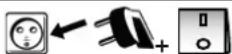
Charging the ENERGY STATION FP's internal batteries
Fitted with a 12 V / 30 A charger, the two internal batteries are recharged one at a time by alternating 30-minute charging cycles.
Connect the batteries to be charged.


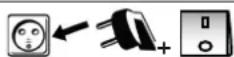
Connect the charger to the 230 V (50 - 60 Hz) mains supply.
Set the battery switch to the 'OFF' position.
Set the switch to the 'ON' position.
Charging will start automatically.
During the charging process, the device will indicate the state of progress.
If recharging only one battery (e.g. in the case of a 12 V start up), disconnect one of the two internal batteries. The recharging time will be much faster.

Being a 12 V charger, the ENERGY STATION FP alternately charges each battery individually for 30 minutes. Any manipulation of the batteries during the charging process is strongly discouraged (replacing batteries or readjusting the polarities if they have been inverted, etc.).
If carrying out an operation on one of the two batteries is absolutely necessary, disconnect the product from the mains supply, carry out the operation and then reconnect it.
line
| Time Interval | Lead Load Curve | | ------------- | --------------- | | <1s | U | | Max 12h | U | | Max 8h | U | | Max 24h | U | | No limit | U |Stage 1 : Analysis
Battery status analysis (charge level, reverse polarity or bad battery connected, etc.).
Stage 4 : Desulphation (15.8 V)
Battery desulphation algorithm.
Stage ② : Recovery (10 A)
An algorithm for recovering damaged elements following a deep discharge.
Stage 5: Charging (30 A)
Rapid charging at the maximum current level to quickly reach 100% charged.
Stage ③ : Test
Sulphated battery test
Stage 6: Charge holding (13.6 V)
Maintaining the batteries at full charge.
Charging an external 12 V battery
It is possible to recharge an external battery. However, in order to charge it faster, it is recommended that the internal batteries are fully charged beforehand.
Charging an external battery
| Connect the cables to the ENERGY STATION FP's 12 V outlet (red cable to the 12 V outlet, black cable to the battery's negative [-] terminal). | |
 | Connect the external battery using the clamps, making sure that the polarity is correct. ▲ |
 | Set the switch to the ‘ON’ position. |
 | Connect the charger to the 230 V (50 - 60 Hz) mains system. |
 | Set the switch to the ‘ON’ position. |
| Charging will start automatically.During the charging process, the device will indicate the batteries' state ofBATTERY 2 progress. |
ANOMALIES, CAUSES AND SOLUTIONS
| Anomalies Causes Solutions | |||
| STARTER MODE | The device beeps and the red LED indicator light turns on. | The device has detected a polarity inversion. | Check the batteries' polarity. Red clamp to the positive (-) battery terminal and black clamp to the negative (-) terminal. |
| at 24 V | Polarity OK. Battery too weak (< 11 V). | ||
| Non-insulated clamps have come into contact with water. | |||
| Sparks emitted when the clamps come into contact with the battery. | The battery switch is in the 'ON' position. | Set the battery switch to the 'OFF' position before connecting the clamps to the battery. | |
| The voltage selector is in the wrong position. | Check that the vehicle's voltage corresponds to the selected voltage. | ||
| Switching the polarities. Check the batteries' polarity. | |||
| The device can no longer start the vehicle. | Internal battery voltage is very low. They may be damaged. | Put the appliance back on charge in an attempt to restore the batteries. | |
| Fuse has burned out. Check / replace the fuse. | |||
| CHARGING MODE | The LED indicator lights are flashing at the same time. | Internal battery (or batteries) is not properly connected. | Wire up the battery (or batteries). |
| The battery (or batteries) is in reverse polarity. | Check polarity. | ||
| The battery (or batteries) is deeply discharged (< 2 V). | Internal battery (or batteries) is not working. | ||
| The two LED indicator lights are permanently on. | Charger's thermal protection. The charger has overheated because the ambient temperature is too high. It will automatically resume charging when the temperature has dropped sufficiently. | ||
| An indicator light is on. | Charging time is too long. Internal battery is not working. | ||
| The indicator lights are flashing. | The battery voltage is too high. Check the wiring. | ||
WARRANTY CONDITIONS
The warranty covers any manufacturing defects or general faults for two years from the date of purchase (parts and labour).
The warranty does not cover:
- Any transportation damage.
- The usual wear and tear of component parts (e.g. cables and clamps, etc.).
- Incidents due to improper use (power-supply errors, falls or dismantling, etc.).
- Environmentally related faults (pollution, rust or dust, etc.).
In the event of a breakdown, please return the appliance to your distributor enclosing:
- dated proof of purchase (receipt or invoice, etc.)
- a note explaining the breakdown
SICHERHEITSHINWEISE

Vorschriften:
natural_image
Technical line drawing of a vehicle chassis with wheels and control panel (no text or symbols)natural_image
Technical line drawing of a mechanical device with wheels and control panel (no text or symbols)line
| Time Period | Voltage (U) | Current (I) | |-----------------------|-------------|-------------| | <1s | High | Low | | Max 12h | High | Low | | Max 8h | High | Low | | Max 24h | High | Low | | No limit | High | Low |Schritt 1: Analyse
natural_image
Technical line drawing of a mechanical device with wheels and control panel (no text or symbols)natural_image
Technical line drawing of a vehicle chassis with wheels and control panel (no text or symbols)natural_image
Technical line drawing of a mechanical device with wheels and control panel (no text or symbols)line
| Time Period | U | I | | --------------------- | ---- | ---- | | <1s | High | Low | | Max 12h | High | Low | | Max 8h | High | Low | | Max 24h | High | Low | | No limit | High | Low |Этап 1 :Анализ
natural_image
Technical line drawing of a vehicle chassis with wheels and control panel (no text or symbols)natural_image
Technical line drawing of a mechanical device with wheels and control panel (no text or symbols)line
| Time Interval | U | I | | ------------- | ---- | ---- | | <1s | High | Low | | Max 12h | High | Low | | Max 8h | High | Low | | Max 24h | High | Low | | No limit | High | Low |Stap 1 : Analyse
natural_image
Technical line drawing of a vehicle chassis with wheels and control panel (no text or symbols)natural_image
Technical line drawing of a mechanical device with wheels and control panel (no text or symbols)line
| Time Interval | U | I | | --------------------- | ---- | ---- | | <1s | High | Low | | Max 12h | High | Low | | Max 8h | High | Low | | Max 24h | High | Low | | No limit | High | Low |Fase 1 : Analisi
| 1 | Porte Fusible / Fuse holder / Sicherungshalter / Porta fusible / Отсек для предохранителя / Zekeringhouder / Porta Fusibile | 51400 |
| 2 | Fusible / Fuse / Sicherung / Fusible / Плавкий предохранитель / Zekering / Fusibile | 054561 |
| 3 | Coupe batterie / Battery-disconnect switch / Batterieschalter / Interruptor de batería / Выключатель аккумулятора / Accu schakelaar / Interruttore | 53147 |
| 4 | Sticker-Clavier / Decal-Keypad / Aufkleber / Sticker-Teclado / Tastatur / Наклейка-клавиатура / Sticker-Toetsenbord / Adesivo-Tastiera | 75114 |
| 5 | Carte électronique (principale + affichage) / Electronic board (main and display) / Platine (Hauptplatine + Anzeige) / Placa electrónica (principal + pantalla) / Электронная плата (основная + дисплей) / Elektronische kaart (hoofd + weergave) / Scheda elettronica (principale + display) | E0105C |
| 6 | Ventilateur / Fan / Lüfter / Ventilador / Вентилятор / Ventilator / Ventilatore | 51018 |
| 7 | Connecteur cordon secteur / Mains cable connector / Netzleitungsanschluss / Conector del cable de alimentación / Разъем шнура питания / Aansluiting netsnoer / Connetore cavo rete | 52431 |
| 8 | Interrupteur M/A / ON/OFF switch / E / A-Schalter / Interruptor de encendido/apagado / Выключатель Вкл/Выкл / Schakelaar ON/OFF / Interruttore M/A | 52460 |
| 9 | Embase texas femelle rouge / Red Texas socket / Grundplatte Texas-Buchse rot / Conector Texas hembra rojo / Красная техасская розетка / Texas aansluiting vrouwelijk rood / Colletto texas femmina rosso | 51471 |
| 10 | Embase texas mâle noire / Black Texas Plug / Grundplatte Texas-Stecker schwarz / Conector Texas macho negro / Гнездо TEXAS папа черный / Texas aansluiting mannelijk zwart / Colletto texas maschio nero | 51472 |
| 11 | Cordon secteur / Power cable / Netzleitung / Cable de conexión eléctrica / Сетевой шнур / Kabel netspanning / Cavo corrente | 22314 |
| 12 | Axe de roue / Wheel axle / Radachse / Eje de la rueda / Ось колес / Wielas / Asse ruota | 98553ST |
| 13 | Roue pleine / Disc wheel / Massives Rad / Rueda completa / Цельное колесо / Massief wiel / Ruota piena | 71365 |
| 14 | Roue pivotante / Castor wheel / Schwenkbares Rad / Rueda giratoria / Поворотное колесо / Zwenkwiel / Ruota girevole | 71860 |
| 15 | Butée arrière / Rear backstop / Hintere Anschlag / Tope trasero / Уnop / Stop achterкант / Tappo posteriore | 56077 |
| 16 | Pince rouge / Red clamp / Rote Klemme / Pinza roja / Красный зажим / Rode klem / Morsetto rosso | 72066 |
| 17 | Pince noire / Black clamp / Schwarze Klemme / Pinza negra / Черный зажим / Zwarte klem / Morsetto nero | 72065 |
| 18 | Support pince / Clamp holder / Klemmenhalterung / Soporte de pinza / Держатель для зажима / Houder klem / Supporto morsetto | 56037 |
| 19 | Poignée / Handle / Gerät / Mango / Ручка / Handvat / Impugnatura 56014 | |
| 20 | Cosse batterie (-) / Negative battery clamp (-) / Batterieklemme (-) / Terminal de la batería (-) / Аккумуляторные наконечники (-) / Pool accu (-) / Terminale della batteria (-) | 054363 |
| 21 | Cosse batterie (+) / Positive battery clamp (+) / Batterieklemme (+) / Terminal de la batería (+) / Аккумуляторные наконечники (+) / Pool accu (+) / Terminale della batteria (+) | 054356 |
| 22 | Jeu de câbles + pinces / Cable and clamp set / Ersatzkabel + Klemmen / Juego de cables + pinzas / Комплект кабелей + зажимы / Set kabels + klemmen / Set di cavi + morsetti | S81029 |
CIRCUIT DIAGRAM / SCHALTPLAN / DIAGRAMA ELECTRICO / ЭЛЕКТРИЧЕСКАЯ СХЕМА / ELEKTRISCHE SCHEMA / SCEMA ELETTRICO
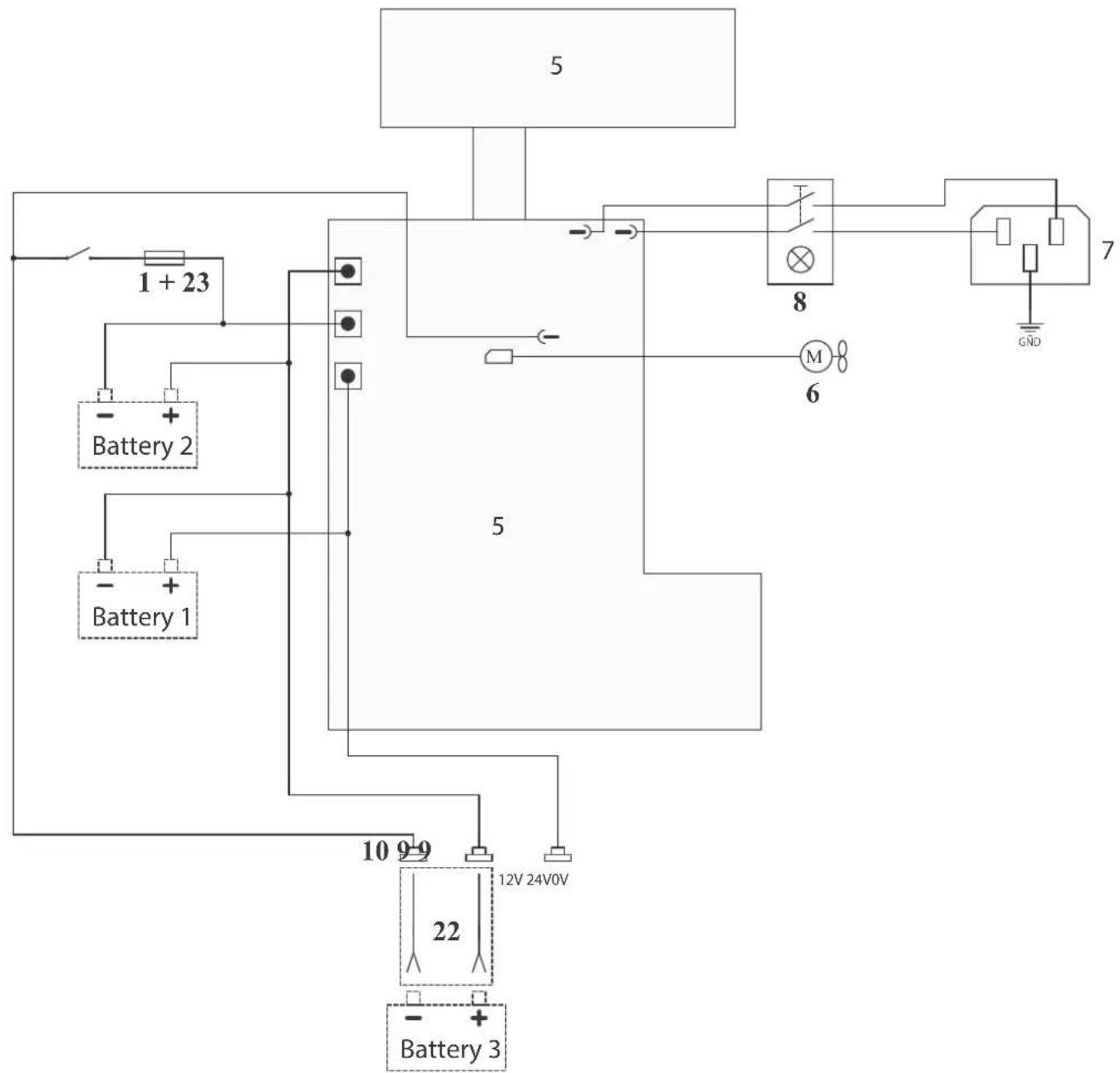
flowchart
graph TD
    A["5"] --> B["1 + 23"]
    B --> C["- Battery 2"]
    B --> D["- Battery 1"]
    C --> E["5"]
    D --> E
    E --> F["8"]
    F --> G["M"]
    G --> H["6"]
    H --> I["7"]
    I --> J["GND"]
    K["10 9-9"] --> L["12V 24V0V"]
    M["22"] --> N["Battery 3"]
    O["-"] --> P["Battery 3"]
TECHNICAL SPECIFICATIONS / TECHNISCHE DATEN / ESPECIFICACIONES TÉCNICAS / ТЕХНИЧЕСКИЕ СПЕЦИФИКАЦИИ / TECHNISCHE GEGEVENS / SPECIFICHE TECNICHE
| Tension d'alimentation / Voltage input / Netzspannung / Voltaje input / Pabочее напряжение / Netspanning / Tensione di alimentazione | 230 V 50/60 Hz |
| Puissance nominale max / Maximum nominal power / maximale nominale Leistung / Potencia nominal máxima / Максимальная номинальная мощность / Maximaal nomi-naal vermogen / Potenza nominale max | 500 W |
| Tension de charge / Charging voltage / Ladespannung / Tensión de carga / Напряжение холостого хода / Laadspanning / Tensione di carica | 12 V |
| Courant de charge / Charging current / Ladestrom / Corriente de carga / Ток заряда / Laadstroom / Corrente di carica | 30 A |
| Capacité nominale de charge / Nominal charging capacity / nominale Batteriekapazität / Capacidad nominal de carga / Номинальная мощность зарядки / Nominale laad-capaciteit / Capacità nominale di carica | 100 à 375 Ah |
| Type de batterie / Battery type / Batterie Typ / Tipo de batería / Категория аккумулятора / Type Accu / Tipo di batteria | Batterie Plomb 12 V(6 éléments de 2 V)12 V lead battery(6 cells of 2 V)12-V-Bleibatterie(6 Elemente zu 2 V)Bateria Plomo 12 V(6 elementos de 2 V)12В свинцово-кислотный аккумулятор (6 x 2В элементов)Lood-accu 12V(6 elementen van 2V)Batteria Piombo 12 V(6 elementi da 2 V) |
| Courbe de charge / Charging curve / Ladekurve / Curva de carga / Charging curve / Laadcurve / Curva di carica | Plomb (6 étapes)Lead (6 stages)Blei (6 Schritte)Plomo (6 pasos)Свинец (6 этапов)Lood (6 stappen)Piombo (6 tappe) |
| Fonction Test / Test function / Testmodus / Función de test / Кривая заряда / Test Functie / | Précision : ± 50 mVPrecision: ± 50 mVGenauigkeit: ± 50 mVPrecision : ± 50 mVTочность ± 50 mBPrecisie : ± 50 mVPrecisione: ± 50 mV |
| Température de fonctionnement / Operating temperature / Betriebstemperatur / Temperature de funcionamiento / Рабочая температура / Werktemperatuur / Temperatura di funzionamento | -20°C - +40°C |
| Température de stockage (sans batteries) / Storage temperature (without batteries) / Lagertemperatur (ohne Batterien) / Temperatura de almacenado (sin pilas) / Температура хранения (без батарей) / Opslagtemperatuur (zonder batterijen) / Temperatura di stoccaggio (senza batterie) | -20°C - +80°C |
| Indice de protection / Protection rating / Clase de protección / Schutzklasse / Класс защиты / Beschermingsklasse / Indice di protezione | IP23 |
| Poids de l'appareil / Machine weight / Gewicht / Peso del aparato / Класс защиты / Gewicht van het apparaat / Poids de l'appareil | 29 kg |
| Dimension (LxlxH) / Dimensions (LxlxH) / Abmaße (LxBxH) / Dimensiones (LxlxH) / Размеры (ДхШхВ) / Afmetingen (LxBxH) / Dimensioni (Lx IxH) | 65 x 70 x 91 cm |
SYMBOLS / ZEICHENERKLÄRUNG / ICONOS / СИМВОЛЫ / PICTOGRAMMEN / ICONE / ICONES
| FR Produit recyclable qui relève d'une consigne de tri. EN This product should be recycled appropriately DE Recyclingprodukt, das gesondert entsorgt werden muss. ES Producto reciclable que requiere una separación determinada. RU Этот аппарат подлежит утилизации. NL Product recyclebaar, niet bij het huishoudelijk afval gooien. IT Prodotto riciclabile soggetto a raccolta differenziata. | |
| IP23 | FR Protégé contre l'accès aux parties dangereuses des corps solides de diam >12.5 mm et protégé contre la pluie dirigée à 60° par rapport à la verticale. EN Protected against access to dangerous parts of solid bodies with diam >12.5 mm and protected against rain directed at 60° to the vertical DE Schutz gegen den Zugang zu gefährlichen Teilen von Feststoffen mit einem Durchmesser >12,5 mm und Schutz gegen Regen, der auf 60° aus der Vertikalen gerichtet ist ESI Protección contra el acceso a partes peligrosas de sólidos con un diámetro >12,5 mm y protección contra la lluvia dirigida a 60° de la vertical. RU Защитa ot доступа к опасным частям твердых частиц диаметром >12,5 mm и защита от дождя, направленного на 60° от вертикали. NL Bescherming tegen toegang tot gevaarlijke delen van vaste stoffen met een diameter >12,5 mm en bescherming tegen regen op 60° van de verticaal. IT Protezione contro l'accesso a parti pericolose di solidi con diametro >12,5 mm e protezione contro la pioggia diretta a 60° dalla verticale. |
GYS France
Siège social / Headquarter