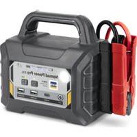
Nomad Power PRO XXL - Battery charger GYS - Free user manual and instructions
Find the device manual for free Nomad Power PRO XXL GYS in PDF.


User questions about Nomad Power PRO XXL GYS
0 question about this device. Answer the ones you know or ask your own.
Ask a new question about this device
Download the instructions for your Battery charger in PDF format for free! Find your manual Nomad Power PRO XXL - GYS and take your electronic device back in hand. On this page are published all the documents necessary for the use of your device. Nomad Power PRO XXL by GYS.
USER MANUAL Nomad Power PRO XXL GYS
natural_image
Technical line drawing of a device rear panel with ports and buttons (no readable text or symbols)NOMAD POWER
PRO XXL
natural_image
Technical line drawing of a device rear panel with ports and connectors (no text or symbols)NOMAD POWER
12 /24 V
PRO 12/24 V
FR 02-09 / 58-60
EN 10-17 / 58-60
DE 18-25 / 58-60
ES 26-33 / 58-60
RU 34-41 / 58-60
NL 42-49 / 58-60
IT 50-57 / 58-60
INSTRUCTIONS DE SÉCURITÉ

text_image
EAC UK CAnatural_image
Technical line drawing of a device rear panel with labeled ports and connectors (no readable text or symbols)Booster Chargeur
natural_image
Line drawing of a plug-in connector with a U-shaped cable (no text or symbols)| PRO XXL 16.8 VDC - 3.8 A | |
| 12/24 V & PRO 12/24 V 29 | VDC - 2 A |
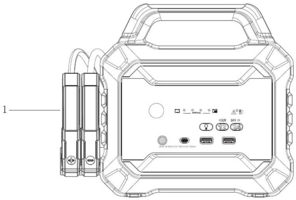
INTERFACE PRODUIT
text_image
Diagram showing cable connection between two devices with labeled components and cable non-fourniestext_image
Diagram showing device connection with USB ports, battery, and charging cable connectionsThis user's manual includes operating instructions for your device and safety warnings for your protection. Please read it carefully before first use and keep it for future reference. These instructions must be read and fully understood before use. Do not carry out any alterations or maintenance work that is not directly specified in this manual. The manufacturer shall not be liable for any damage to persons or property resulting from use not in accordance with the instructions in this manual. In the event of any problems or concerns, please seek advice from a suitably qualified person to ensure that the product is being operated correctly. This machine must only be used for starting and/or supplying power within the limits indicated on the machine and in the manual. The safety instructions must be followed. In the event of improper or dangerous use, the manufacturer cannot be held responsible.

The device is designed to be used indoors. Must not be exposed to the rain.
This unit can be used by children aged eight or over, by people with reduced physical, sensory or mental capabilities as well as by those with a lack of experience or knowledge. However, these aforementioned persons must be properly supervised and they must have read and understood the user instructions, alongside having been made aware of the risks. Children must not play with the product. Cleaning and maintenance should not be performed by an unsupervised child.
Do not use to charge domestic batteries or non rechargeable batteries.
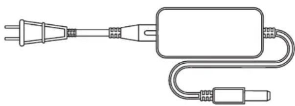
Only use the charger supplied with the device to recharge the batteries.
Never start a vehicle without a battery.
Do not use the charger if the mains cable or plug is damaged.
In order to avoid short-circuiting the battery, do not use the appliance if the charging cable is damaged or has an assembly defect.
Never charge a frozen or damaged battery.
Do not cover the device.
Do not place the unit near a heat source, direct sunlight or continuously high temperatures (above 50 °C ).
There is a risk of explosion or acid projection if the clamps are short-circuited, or if the 12 V booster is connected to a 24 V vehicle, or vice versa.

The automatic operating mode and the relevant usage restrictions are explained later in this manual.
Fire and explosion risks!
A charging battery can emit explosive gases.
- Avoid flames and sparks. Do not smoke near the device.
- Protect the battery's electrical contact surfaces against short-circuits

Risk of acid dispersion!
- Wear protective goggles and gloves.
- In case of contact with the eyes or the skin, rinse with water immediately and seek medical attention as soon as possible.
Connection / disconnection:
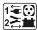
- Disconnect the power supply before plugging or unplugging the connections to/from the battery.
- Always ensure the red clamp is connected to the «+» battery terminal first. If it is necessary to connect the black clamp to the chassis of the vehicle, make sure it is a safe distance from the battery and the fuel/exhaust pipe.
- After starting, disconnect the booster. Remove the connection to the chassis first, followed by the battery connection, in the order shown.

Class II device (charger).
The power cable cannot be replaced. If the cable is damaged, the device must be disposed of (charger).

Maintenance:
- Maintenance should only be carried out by a qualified person.
- Warning! Always disconnect from the mains before carrying out maintenance on this machine.
- Never use solvents or other aggressive cleaning agents.
- Clean the surfaces of the unit with a dry cloth.

Regulations:
• This device complies with European directives.
- The Declaration of Conformity is available on our website.
• EAC conformity mark (Eurasian Economic Community).

- This equipment conforms to UK requirements.
- The UK Declaration of Conformity is available on our website (see cover page).
- This equipment conforms with Moroccan standards.
- The C _o (CMIM) Declaration of Conformity is available on our website (see cover page).
Disposal:
- This product should be disposed of in an appropriate recycling facility. Do not dispose of in domestic waste.
- The battery must be removed from the unit before it is disposedof.
- The battery must be dropped off at a suitable recycling facility
- The unit must be disconnected from the power supply before removing the battery.
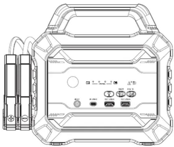
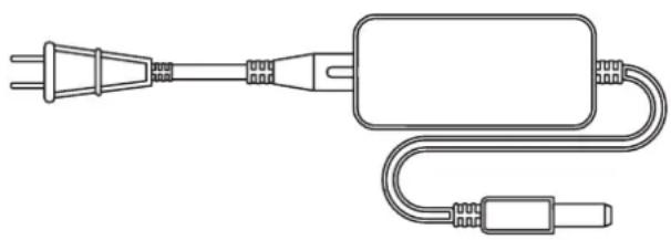
PACK CONTENTS
natural_image
Technical line drawing of a device rear panel with ports and connectors (no text or symbols)Booster Charger
natural_image
Line drawing of a plug-in connector with terminal connections (no text or symbols)| PRO XXL 16.8 VDC - 3.8 A | |
| 12/24 V & PRO 12/24 V 29 | VDC - 2 A |
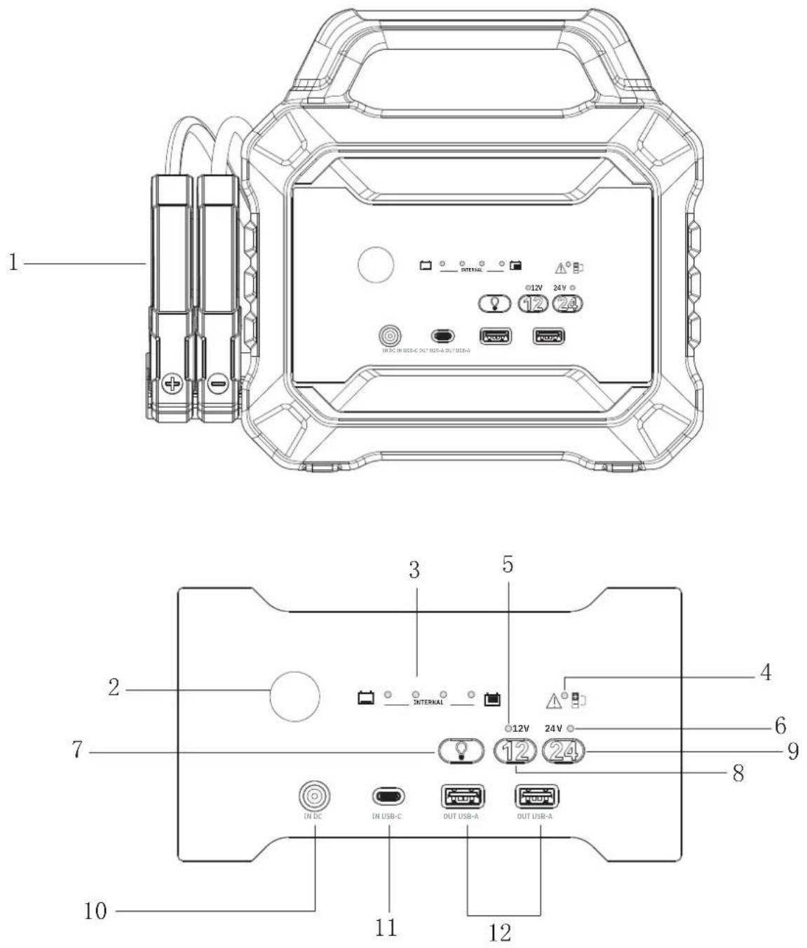
PRODUCT INTERFACE
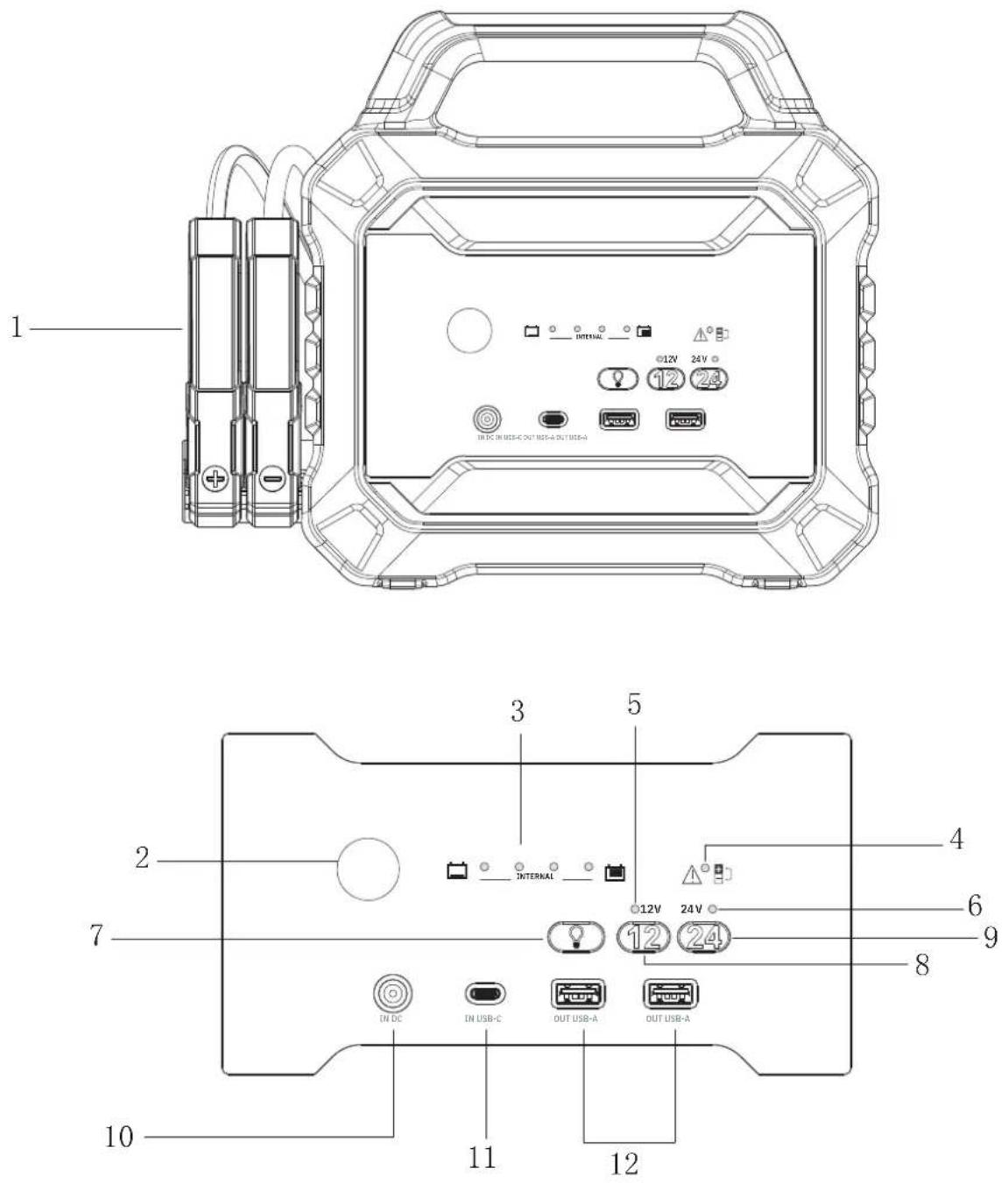
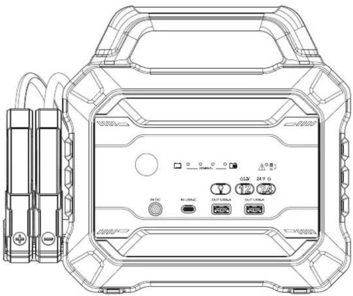
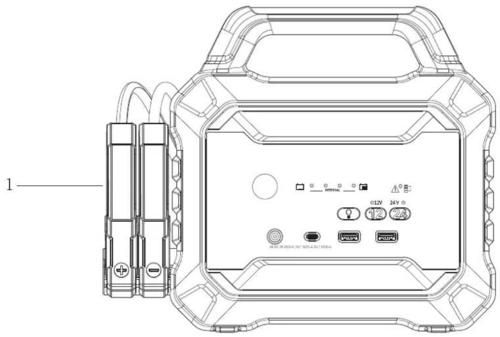
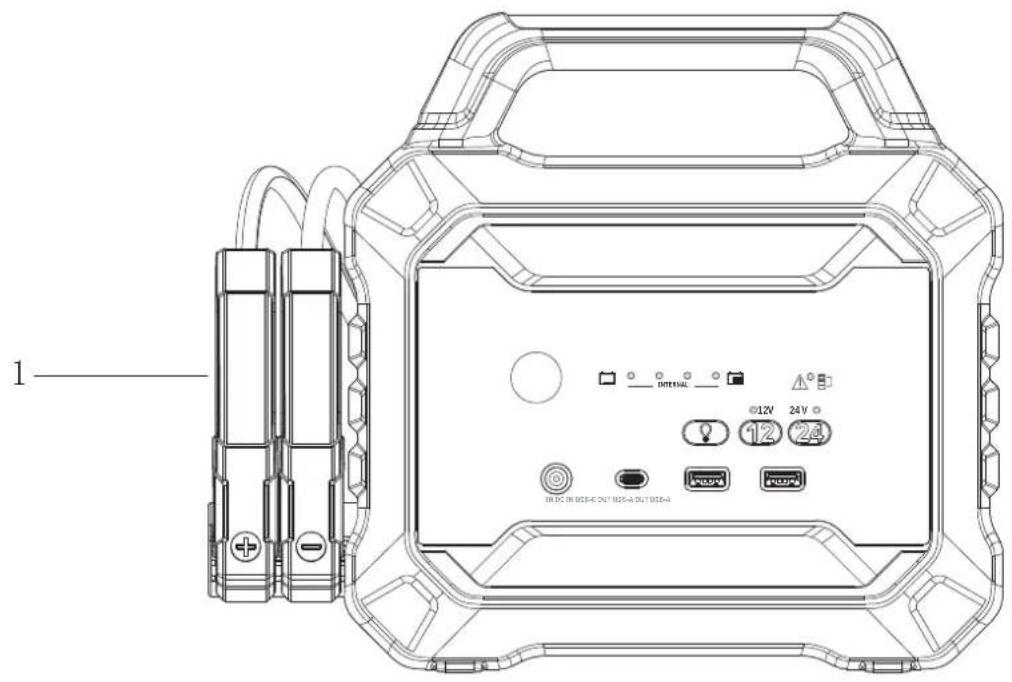
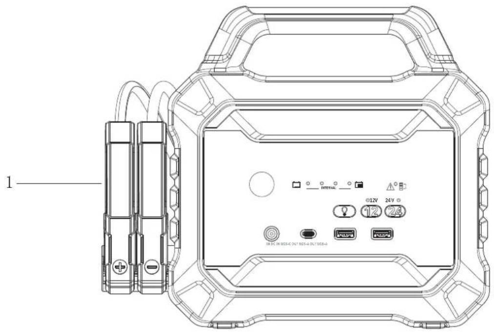
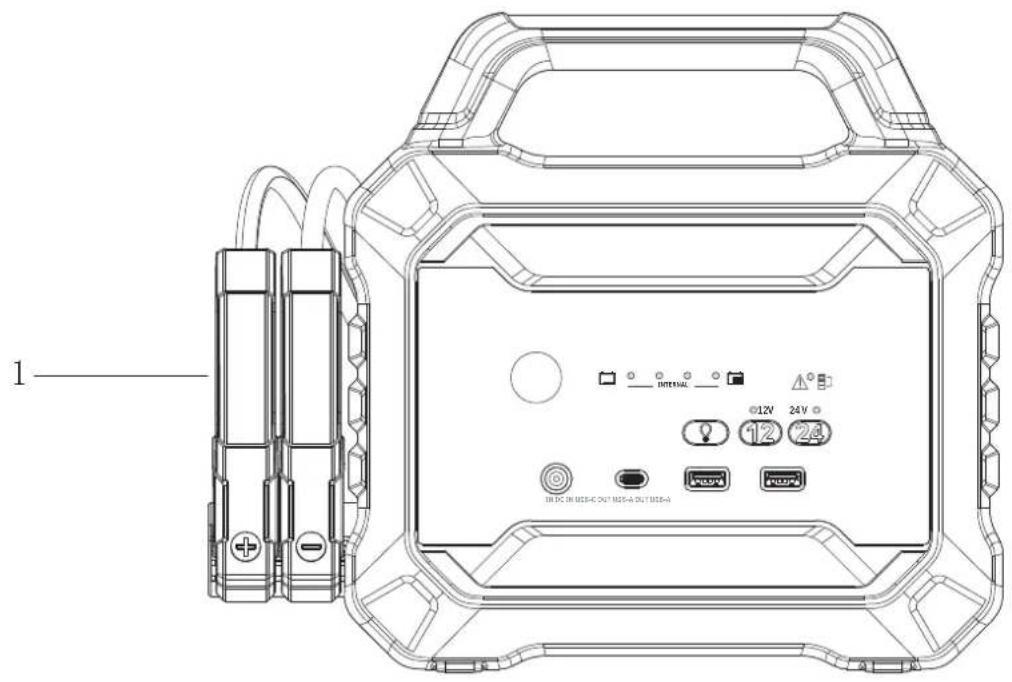
| 1 Starter clamps | |
| 2 | Lamp |
| 3 Internal battery charge indicators | |
| 4 Fault indicator | |
| 5 12 V mode active LED | |
| 6 24 V mode active LED (12/24 V models only) | |
| 7 Lamp activation button | |
| 8 12 V SOS mode button | |
| 9 24 V SOS mode button (12/24 V models only) | |
| 10 «IN DC» input port (PRO XXL : 16.8 VDC - 4 A, 12/24 V & PRO 12/24 V : 29 VDC - 5 A) | |
| 11 USB-C input port | |
| 12 USB-A Output ports | |
BATTERY CHARGE STATUS
Press any button. The LEDs indicate the charge level of the internal battery.
| Charge indicators 25% | flashing | 1 light on | 2 lights on | 3 lights on | 4 lights on |
| Charge level 0 % ≤ 25% | ≤ 50% ≤ 75% ≤ 100% |
- During charging, the LEDs light up one by one.
- When the battery reaches the next level of charge, the corresponding LED lights up and the next one starts flashing.
- The internal battery is charged when the 4 LEDs light up together, then turn off, indicating that charging is complete.
INTERNAL BATTERY CHARGING

It is preferable to charge the Nomad Power at a temperature >10^ . Do not recharge at temperatures below 0^ . Put the Nomad Power in a room temperature location for 1 hour before charging.
Recharge the NOMAD POWER to 100% every 6 months, if it has been out of use for a long time, as this will help to maintain its performance.
text_image
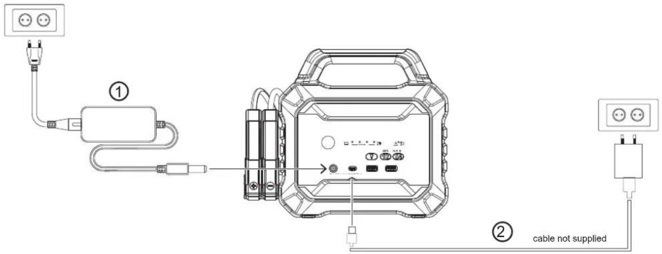
Diagram showing cable connection with labeled components and notes in EnglishThe booster has two input ports: an «IN DC» input port, and a USB type-C input.
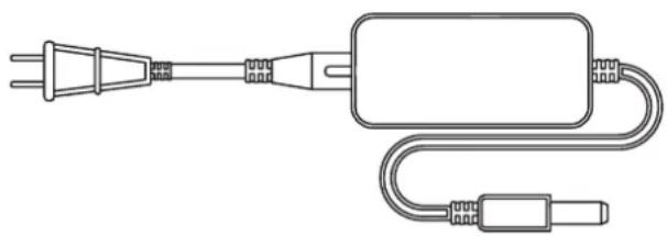
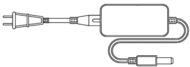
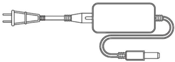
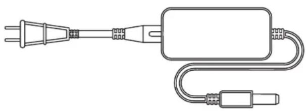
- Standard charge: connect the DC charger, supplied with the booster, to the «IN DC» input port (10).
- Charge via USB port (slow): connect a USB Type-C cable (not included) to the USB-C input port on the booster. Then connect the other end of the cable to a USB port, such as a wall socket or the USB socket in a vehicle.

The two input ports do not allow charging at the same time; the 29 VDC input has priority.
USING THE MACHINE IN BOOSTER MODE

Do not start a Lithium LiFePO4 battery with this booster as it is equipped with a Lithium LiCoO2 battery, and the voltage is not compatible.
- Press any button to switch the unit on, and to check the charge status of the internal battery. To maximise the chances of a successful start, the booster must be 100% charged before use.
- Connect the red clamp to the + terminal of the battery in the vehicle.
- Connect the black clamp to the - terminal of the battery in the vehicle.
- The 12 V and 24 V mode LEDs light up to indicate what steps to take:
| LED status Meaning Action | ||
| One of the 12 V or 24 V LEDs is flashing or steady. | Good connection. Proceed with the start attempt. | |
| The 12 V and 24 V LEDs flash at the same time. | The vehicle battery is weak, the booster cannot identify if the battery voltage is 12 V or 24 V. | SOS mode is required.SEE SOS MODE. |
| No LEDs are lit. No connection detected:1. Poor connection between clamps and battery terminals.2. The voltage of the battery in the vehicle is extremely low. La tension de la batterie du véhicule est extrêmement basse. | Check that the connections between the clamps and the battery terminals are clean and secure.If, after checking that the clamps are properly connected, both lights are off, you will need to use SOS mode.SEE SOS MODE. | |

Only start when the charge level is sufficient: At least 3 charge level LEDs must be lit.
Do NOT start more than 3 times in a row. This could cause damage if the unit overheats. Wait for at least two minutes between each attempt.
- After having started the vehicle, remove the jump leads from the vehicle's battery. Leave the vehicle's engine running.
USING THE MACHINE IN SOS MODE
The SOS function can be used to force start a vehicle if the battery is too low. This means that it is possible to start a vehicle, even when the starter battery voltage is 0 V.

SOS mode should be used with extreme caution:
The spark protection and reverse polarity protection functions are deactivated in this mode:
- Check the polarity of the battery before connecting.
- The positive and negative clamps must not come into contact with each other.
- Do not connect a 12 V vehicle if the 24 V SOS mode is activated.
- Do not connect a 24 V vehicle if the 12 V SOS mode is activated.
- This mode delivers a very high level of current, which can cause sparks and intense heat if used incorrectly.
- If in doubt about the voltage of the battery in the vehicle: 12 or 24 V, please contact a professional.
- If in doubt about how to use this mode, please ensure you speak with trained personnel.
Process procedure
- Make sure the polarity of the clamps is correct (red clamp to the + terminal, and black clamp to the - terminal of the battery).
- Identify the battery voltage: 12 or 24 V, then press and hold the corresponding mode button (>2 s).
- The 12 V or 24 V LED lights up continuously, indicating that SOS mode has been activated.
- Carry out the start attempt within 30 seconds.
Note: the SOS mode is only active for 30 seconds. Once this time has elapsed, the product resets. The procedure has to be restarted from the beginning.
USING THE MACHINE IN POWER BANK MODE
text_image
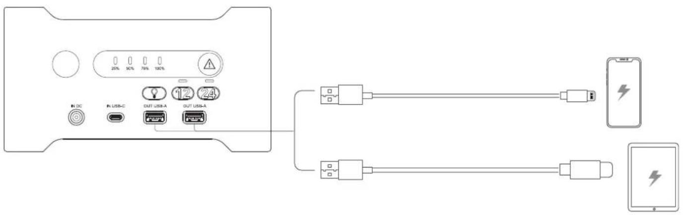
Diagram showing connection between a device panel with USB ports and two connected devices via battery charging.This booster has two USB-A output ports, ideal for recharging portable electronic devices such as smartphones and tablets, etc.
- Connect the device(s) to the USB output port(s) using a suitable USB charging cable (not included).
- Press any button to switch the unit on and activate the USB power supply.
LAMP FUNCTION
Press the ⏻ button to activate the light. Press the button again to switch between lighting modes: On → Strobe → SOS → Off
TROUBLESHOOTING
| Analysis Causes Solution | ||
| The fault indicator is on. Polarity reversal | al. Check that the clamps are connected to the battery. | |
| The unit will not activate. | Overload protection may have been triggered. | Charge the unit. If it still cannot be activated, contact your distributor. |
| The unit is not charging. | The AC charger or USB port is not powered. | Replace the AC charger or connect the USB cable to another USB port. |
| The USB cable is faulty. | Replace the USB cable. If you are still unable to charge the unit, contact your distributor. | |
| The 12 V light flashes or stays steadily on, but the booster cannot start the vehicle. | 1. The battery in the vehicle is 24 V, but the voltage has dropped to 12 V.2. Mechanical problem with the vehicle. | Check that the battery in the vehicle is 24 V. If so, use the 24 V SOS mode. |
| The red fault indicator flashes. Overheat protection is activated. | Stop using the unit and wait for it to cool down. | |
| The 25% / 50% / 75% LEDs flash at the same time while the device is charging. | The internal temperature of the battery is too low and recharging is not possible. | Leave the device in an area at room temperature, and do not recharge it until the internal battery has warmed up. |
| The 25% / 50% or 50% / 75% LEDs flash at the same time while the device is charging. | The AC charger is not original, and is not compatible with the booster. | Use a suitable charger to recharge the unit. |
| The 25% LED flashes rapidly. The internal battery is out of order. | Contact your distributor if the unit is still under warranty, or replace it. | |
WARRANTY
The warranty covers all defects or manufacturing faults for a period of two years starting from the date of purchase (parts and labour).
The warranty does not cover:
- Any other damage caused during transport.
- The general wear and tear of parts (i.e. : cables, clamps, etc.).
- Incidents caused by misuse (incorrect power supply, dropping or dismantling).
- Environment-related faults (such as pollution, rust and dust).
In the event of a breakdown, please return the item to your distributor, along with:
- a dated proof of purchase (receipt or invoice etc.).
a note explaining the malfunction.
SICHERHEITSHINWEISE

text_image
CE EAC UK CAVorschriften:
natural_image
Technical line drawing of a portable electronic device with ports and connectors (no text or symbols)Booster Ladegerät
natural_image
Line drawing of a plug and plug connector (no text or symbols)| PRO XXL 16.8 VDC - 3.8 A | |
| 12/24 V & PRO 12/24 V 29 | VDC - 2 A |
GERÄTESCHNITTSTELLE
text_image
1 INTERNAL @12V 24V 12 24 IN OC IN MSS-C OUT MSS-A OUT MSS-A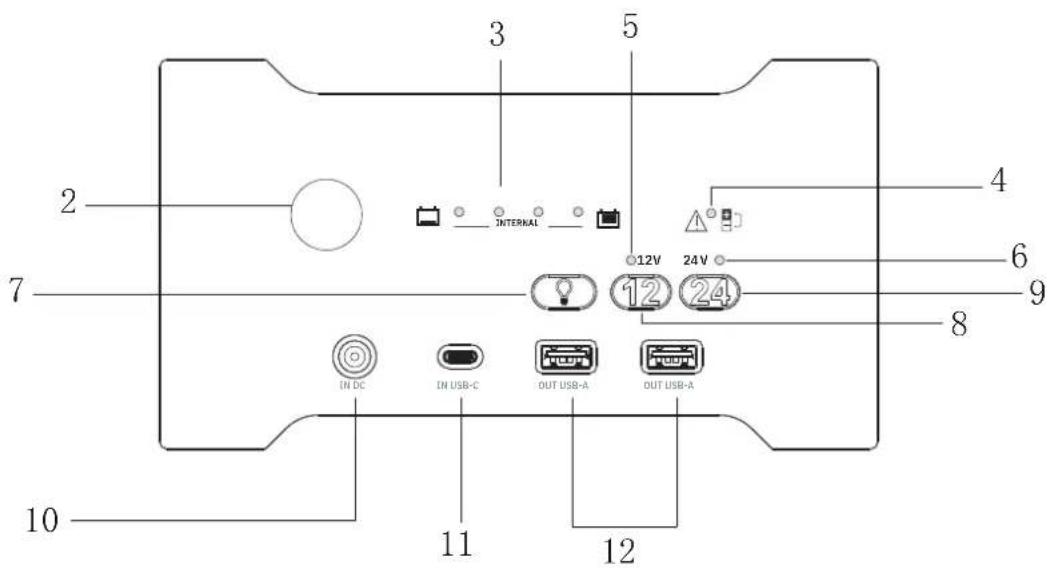
text_image
3 5 2 INTERNAL 12V 24V 6 7 12 8 IN DC IN USB-C OUT USB-A OUT USB-A 10 11 12text_image
Diagram showing connection between a device panel with USB ports and two connected devices via USB interfaces.natural_image
Technical line drawing of a device rear panel with ports and connectors (no text or symbols)Booster
natural_image
Line drawing of a plug-in connector with a terminal block and cable (no text or symbols)Cargador
| PRO XXL 16.8 VDC - 3.8 A | |
| 12/24 V & PRO 12/24 V 29 | VDC - 2 A |
INTERFAZ DEL PRODUCTO
text_image
1 ©12V 24V © 12 24 IN DC IN MDS-C OUT MDS-A OUT MDS-B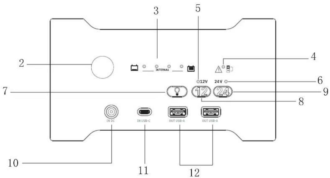
text_image
2 3 5 4 6 7 8 9 10 11 12 IN DC IN USB-C OUT USB-A OUT USB-Atext_image
Diagram showing connection between a device panel with USB ports and two connected devices via USB interfaces.natural_image
Technical line drawing of a device rear panel with labeled ports and connectors (no readable text or symbols)natural_image
Line drawing of a plug and cable connector (no text or symbols)| PRO XXL 16.8 VDC - 3.8 A | |
| 12/24 V & PRO 12/24 V 29 | VDC - 2 A |
ИНТЕРФЕЙС ПРОДУКТА
text_image
1 ©12V 24V © 12 24 IN DC IN MDS-C OUT MDS-A OUT MDS-B
text_image
3 5 2 INTERNAL 12V 24V 6 7 12 8 IN DC IN USB-C OUT USB-A OUT USB-A 10 11 12text_image
Diagram showing device connection with USB ports, battery, and charging cable connectionsnatural_image
Technical line drawing of a device rear panel with labeled ports and connectors (no readable text or symbols)Booster
natural_image
Line drawing of a plug and cable connector (no text or symbols)Lader
| PRO XXL 16.8 VDC - 3.8 A | |
| 12/24 V & PRO 12/24 V 29 | VDC - 2 A |
BEDIENING VAN HET APPARAAT
text_image
1 ©12V 24V © 12 24 IN DC IN MDS-C OUT MDS-A OUT MDS-B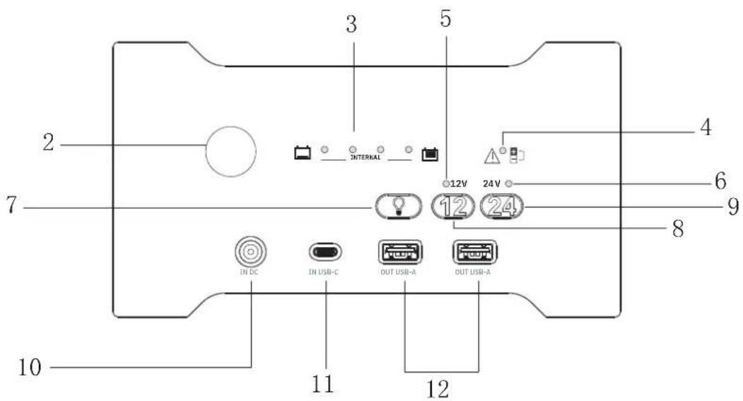
text_image
2 3 5 4 6 7 8 9 10 11 12 IN DC IN USB-C OUT USB-A OUT USB-Atext_image
Diagram showing connections of a device with labeled components and a note indicating 'kabel niet meegeleverd'text_image
Diagram showing connection between a device panel with USB ports and two connected devices via USB and battery cables.natural_image
Technical line drawing of a device rear panel with ports and connectors (no text or symbols)Booster
natural_image
Line drawing of a plug-in connector with a U-shaped cable (no text or symbols)Caricabatterie
| PRO XXL 16.8 VDC - 3.8 A | |
| 12/24 V & PRO 12/24 V 29 | VDC - 2 A |
INTERFACCIA PRODOTTO
text_image
1 ©12V 24V © 12 24 IN DC IN MDS-C OUT MDS-A OUT MDS-B