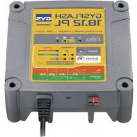
Startflash 120.24 CNT - Battery charger GYS - Free user manual and instructions
Find the device manual for free Startflash 120.24 CNT GYS in PDF.
Questions des utilisateurs sur Startflash 120.24 CNT GYS
0 question sur cet appareil. Repondez a celles que vous connaissez ou posez la votre.
Poser une nouvelle question sur cet appareil
Download the instructions for your Battery charger in PDF format for free! Find your manual Startflash 120.24 CNT - GYS and take your electronic device back in hand. On this page are published all the documents necessary for the use of your device. Startflash 120.24 CNT by GYS.
USER MANUAL Startflash 120.24 CNT GYS
- Les pannes liées à l’environnement (pollution, rouille, poussière). En cas de panne, retourner l’appareil à votre distributeur, en y joignant : - un justicatif d’achat daté (ticket de sortie de caisse, facture….) - une note explicative de la panne.18 User manual STARTFLASH CNT Translation of the original user manual SAFETY INSTRUCTIONS This user manual includes information on how to safely operate this equipment and the safety precautions to be followed. Please read it carefully before rst use and keep it somewhere safe for future reference. These instructions must be read and understood before operating the machine. Do not undertake any modication or maintenance work that is not specied in the user manual. The manufacturer shall not be held responsible for any damage to persons or property caused by using the product in a manner not in accordance with the instructions in this user manual. If you have any problems or queries, please consult a qualied technician to ensure that the equipment is used correctly. This device may only be used for recharging, starting and/or supplying power within the limits indicated on the product and in the user manual. The safety instructions must be observed. The manufacturer cannot be held responsible in the event of improper or dangerous use. This appliance is intended for indoor use. Do not expose it to rain. This appliance may be used by children as young as eight years old and by persons with reduced physical, sensory or mental capabilities, as well as by those who lack experience or knowledge, if they are properly supervised or if they have been given instructions on how to use the device safely and if the risks involved have been properly understood. Children must not play with this device. Do not let unsupervised children carry out cleaning or maintenance work on this equipment. Never use this product to charge non-rechargeable batteries. Do not use the appliance if the power cable or plug is damaged. Never charge a frozen or damaged battery. Do not cover the appliance. Do not place the charger near a heat source, nor at a permanently high temperature (above 60°C). Do not obstruct the ventilation openings. The automatic operating mode and the usage restrictions are explained below in this user manual. Explosion and re hazard!
- A charging battery may emit explosive gases.
- The battery should be placed in a well-ventilated area when charging.
- Protect the battery’s electrical contact surfaces from short circuits. Do not leave batteries unattended for long periods of time while they are being charged.FR
- Wear protective goggles and gloves.
- In the event of contact with eyes or skin, rinse with water and seek medical advice immediately. Connecting to / Disconnecting from the power supply:
- Disconnect the power supply before connecting or disconnecting battery terminals.
- The battery terminal that is not connected to the chassis must be connected rst. The other terminal should be connected to the chassis far away from the battery and the fuel line. The battery charger must then be connected to the mains system.
- After charging, rst disconnect the battery charger from the mains system, then, remove the chassis connection and nally, the battery connection, in the order indicated. Connecting:
- This device must be connected to an earthed mains outlet.
- This equipment is intended to be used in industrial environments (Class A) and is not intended for use in a residential setting where power is supplied from the public, low-voltage supply network. There may be potential diculties in ensuring electromagnetic compatibility at these sites due to conducted, as well as radiated, radio-frequency interference. Maintenance:
- If the power cable becomes damaged, it must be replaced with a special cable or assembly; this is available from the manufacturer or their after-sales service.
- Maintenance work should only be carried out by a qualied technician.
- Warning! Always disconnect the plug from the power outlet before carrying out any maintenance work on the appliance.
- If the internal fuse is blown, it must be replaced by the manufacturer, their after-sales service or a similarly qualied technician to avoid a safety hazard.
- Remove the cover regularly and blow out the dust. Take this opportunity to have the electrical connections checked with an insulated tool by a qualied technician.
- Never use solvents or other aggressive cleaning agents.
- Clean the appliance’s surfaces with a dry cloth. Regulations:
- This device complies with European directives.
- The declaration of conformity is available on our website.20 User manual STARTFLASH CNT Translation of the original user manual
- EEC (Eurasian Economic Community) mark of conformity
- This product complies with UK directives. The UK declaration of conformity is available on our website (see the cover page).
- This device complies with Moroccan standards.
- The Cم (CMIM) declaration of conformity is available on our website. Disposing of this device:
- This hardware is subject to specic disposal regulations. Do not dispose of this equipment in domestic waste.
- The battery must be removed from the unit before it is discarded.
- The battery must be disposed of at a suitable recycling facility.
- The device must be disconnected from the power supply before removing the battery. GENERAL DESCRIPTION Your STARTFLASH device is a professional, multi-functional starter-charger featuring inverter technology. It supports the vehicle’s batteries during diagnostic testing and guarantees optimal charging quality for maintaining and servicing the most advanced battery models. It is also designed to start all types of 12 and 24 V batteries. This charger-starter accepts output cables up to 5 m. In order to change the charging cables, the machine must be recalibrated (see page 12). This device is considered a xed appliance and not a mobile one.Your STARTFLASH unit is delivered with a conguration that includes four separate modes:
- Charging mode: designed to recharge lead (sealed, liquid and AGM) or lithium (LiFePO4) starter batteries.
- Power mode | BSU: provides the energy required during the vehicle’s diagnostic phase.
- Start-up mode: starts vehicles with both 12 and 24 V lead (sealed, liquid and AGM) or lithium (LiFePO4) batteries.
- Testing mode: is used to check the battery’s condition, to evaluate the vehicle’s starting ability and to check the alternator is working properly.Your SMART STARTFLASH device! Your STARTFLASH’s standard features can be enhanced by adding specic charging modes and proles using its USB connec- tion and customised conguration function (see page 13). Your STARTFLASH appliance also oers the option of recovering data from several hundred loads directly onto a USB key to be analysed on a computer spreadsheet. Additional modules (such as printers and Ethernet connections, etc.) can also be connected to the charger via its specic module socket.Auto-Detect feature: The STARTFLASH is equipped with an Auto-Detect feature; this automatically starts the charging process when a battery is connected to the charger. To enable/disable this function, see page 11.Auto-Restart feature:The Auto-Restart feature means that the charger will automatically restart in the event of a power failure. To enable/disable this function, see page 11. GETTING STARTED 1.) Connect the STARTFLASH to the mains socket.2.) Set the switch on the front of the charger-starter to the ON position.3.) Use the turn dial to scroll through the menu. Highlight the desired mode and press to select the chosen mode ( Charge BSU Start -> Test
4.) The syst em menu can be used to congure the STARTFLASH as required. It can also be accessed from each individual mode’s menu by pressing the button at the top left of the window. Mode Charge BSU Starter The and arrows allow the user to return to the previous menu regardless of which section of the menu or settings they are currently in.FR
- General browsing: Groupe Group Pb-CHARGE Li-CHARGE TRACTION When accessing the mode, select the battery technology to be charged. Charging type Prole Charging voltagePb-CHARGE(normal) 2.40 V / cell Charges gel, MF, EFB and SLA lead-acid batteries.AGM 2.45 V / cellMost AGM lead-acid batteries, including stop-start.However, some AGM batteries require a lower charging voltage (normal prole). If in doubt, please refer to the battery’s manual.liquid 2.45 V / cell Open liquid-type lead-acid batteries with cap.easy 2.40 V / cellA specic prole for lead-acid batteries that automatically adapts the charging current according to the battery’s size.However, using the normal, AGM or liquid charging curves is advised wherever pos-sible for the best possible charging process.boost 2.42 V / cellMaximum current charging prole for lead-acid batteries. This prole can be used for ultra-fast charging. recovery+ 2.40 - 2.50 V / cell Specic recovery charging prole for heavily damaged, lead-acid batteries. Li-CHARGELFP/LiFePO4 3.60 V / cell Charging prole for LFP (Lithium Iron Phosphate) batteries.Li-ion std 4.20 V / cellCharging prole for standard manganese- or cobalt-based lithium-ion batteries (NMC, LCO, LMO, MCO, etc.).LFP cell+ 3.60 V / cellA custom-designed charging prole for LFP (lithium-ion phosphate) cells with a feature allowing the user to select the number of cells to be charged in series.Li-ion cell+ 4.20 V / cellA specic manganese- or cobalt-based, standard, lithium-ion cell charging prole (NMC, LCO, LMO, MCO, etc.) with as feature allowing the user to select the number of cells to be charged in series.TRACTION liquid 2.42 V / cell Charging prole dedicated to open lead-acid traction batteries for forklift trucks. gel 2.35 V / cell Charging prole dedicated to forklift gel-type traction batteries. It is possible to set the curve prole, voltage and capacity for each charging technology. To do this: 1 Scroll through the menu using the turn dial. 2 Press the turn dial to enter a parameter setting. 3 Use the turn dial to change the setting’s value. 4 Press the turn dial to conrm the new parameter setting.
- Starting the charging process:
To start charging, use the turn dial to move to the arrow at the top right of the screen and press the turn dial. Pb-CHARGE liquid 12 V Charge If the Auto-Detect feature is active, the charging process will automatically start after the battery has been connec- ted for ve seconds.
3 Scrolling through sections (using the turn dial) provides further information during the charging process:
1 - The stage, the progress (as a percentage) and the
2 - The voltage, current and ampere hours supplied.
To stop charging, press the turn dial. Move the cursor to , then, press the turn dial again.22 User manual STARTFLASH CNT Translation of the original user manual Warnings: It is advisable to reduce the vehicle’s power consumption to a minimum (switching o the lights, turning o the ignition and closing the doors, etc.) when charging a vehicle; this is in order to avoid disrupting the charging process. Check the electrolyte level for open batteries. Top up levels before charging, if necessary.
- Charging stages Charging curve LEAD:
Refresh (si option active)10% 20% 80% 98% 100% Stage 1: Analysis Battery-status analysis (charge level, reverse polarity, wrong battery connected etc.) Stage 6: Absorption Constant voltage charging to bring the charge level up to 100%. Stage 2: Recovery Algorithm for recovering damaged ele- ments following a deep discharge. Stage 7: Absorption Test Charge retention test. Stage 3: Testing Sulphated battery test. Stage 8: Refresh (only for the liquid-bat- tery prole) The charger supplies additional power to create a gas that mixes the electrolytes and reconditions the battery cells. The battery may lose a little water during this phase. Stage 4: Desulphation Battery desulphation algorithm. Stage 5: Charging Fast charging at maximum current to achieve an 80% charge level. Stage 9: Charge holding Maintaining the battery’s charge level at its maximum level.FR
User manual STARTFLASH CNT Translation of the original user manual Lithium charging curve LFP:
Equalising Battery System 2% 85% 95% 99% 100% Stage 1: Analysis Battery-status analysis (charge level, reverse polarity, wrong battery connected etc.) Stage 6: Testing Charge retention test. Stage 2: UVP Wake up Reactivates batteries in UVP protection (Under Voltage Protection) Stage 7: Additional information Reduced current charging to achieve a 100% charge level. Stage 3: Recovery Recovery algorithm following a deep discharge. Stage 8: Equalisation / balancing Balancing the battery cells Stage 4: Charging Fast charging at maximum current to achieve an 90% charge level. Stage 9: Charge holding Maintaining the battery’s charge level at its maximum level. Stage 5: Absorption Constant voltage charging to bring the charge level up to 95%.
POWER SUPPLY MODE | BSU
- General browsing: 1 Scroll through the menu using the turn dial. BSU 12 V
SHOWROOM Ensures that the battery’s state of charge is maintained and that the demonstration vehicle’s energy requirements are met when using electrical accessories. DIAG+ Provides the energy required during the vehicle’s diagnostic phase. CHANGE BAT. Allows the vehicle’s power supply to be maintained when the battery is replaced; this preserves the vehicle’s ECU memory.Warning: reversing the polarity during use can damage the charger and the vehicle’s electronics. POWER SUPPLY Allows the charger to be used as a high-power, adjustable and stabilised power supply. The voltage to be regulated and the current limits are fully adjustable.Warning: reversing the polarity during use can damage the charger and the vehicle’s electronics. Li-SUPPLY/LFP This mode is designed to supply LFP (lithium-ion phosphate) cells with additional features, such as selecting the number of cells in series and adjusting the voltage and current to be delivered. Li-SUPPLY/Li-ion This mode is aimed at supplying manganese- or cobalt-based, standard, lithium-ion cells (NMC, LCO, LMO, MCO, etc.); it also boasts a range of special features, including the possibility of selecting the number of cells in series and adjusting the voltage and current to be delivered.24 User manual STARTFLASH CNT Translation of the original user manual Power limitation : If the ʺ*ʺ symbol appears next to the electrical-current settings (e.g. I: 50A*), this means that the charger is not be able to deliver this current level at the voltage specifed on the screen. Because at this voltage, the charger will be at its maxi- mum power. However, this current may be delivered for lower voltages, depending on the charger’s power limitation.
- Starting the charging process:
To start charging, use the turn dial to move to the arrow at the top right of the screen and press the turn dial. BSU 12 V
If the Auto-Detect feature is active, the charging process will automatically start after the battery has been connec- ted for ve seconds.
Scrolling through sections (using the turn dial) provides further information during the charging process:
1 - The injected voltage, current and ampere hour as well
as the duration of the current operation.
To stop charging, press the turn dial. Move the cursor to , then, press the turn dial again. Warnings: When starting the mode, a current reading of more than 10 A means that your battery is discharged. Your STARTFLASH will then deliver a charging current. Check that there are no electrical consumers on the vehicle. Wait until the current drops below 10 A before starting any procedures on the vehicle (using the vehicle’s electrical devices or diagnostic procedures, etc.). Power-supply mode features: Mode No-battery feature Built-in charging feature Abnormal undervoltage protection Voltage adjustment to be regulated SHOWROOM
- No battery feature (not recommended): This feature allows the SHOWROOM power mode to be used without a battery. To do this, go into SHOWROOM mode and set the parameters in the usual way. Move the cursor over the arrow in the same way as when launching standard charging, however, keep the turn dial pressed down for three seconds to start the charging process. The No-battery feature message is displayed for three seconds before the power is forced on. BSU 12 V
It is not recommended to use the no-battery feature if a battery is installed. This function disables the built-in charging feature as well as certain safeguards, such as abnormal un- dervoltage protection or disconnection detection. In this conguration, reversed polarity can damage the vehicle’s electronics.
- Built-in charging feature: SHOWROOM mode (excluding the no battery feature) has an automatic charging algorithm for all battery types (lead and lithium) to ensure that demonstration vehicles are kept at an optimal charging level. This feature is perfectly compatible with the battery’s electrical consumers. 3sFR
Analyse Charge Complément Égalisation / Equilibrage Mode alimentationAbsorption Stage 1: AnalysisBattery condition analysis (level of charge and reversal polarity, wrong battery connected, etc).Stage 4: Additional informationGradual voltage increase to U2 (e.g. 14.4 V in ). Maximum duration: two hours. Stage 2: ChargingFast charging at maximum current up to U1. (e.g. 13.8 V in ).Stage 5: Equalisation / balancing Maintaining the U2 voltage (e.g. 14.4V in ). Maximum duration: two hours. Stage 3: AbsorptionCharging at a constant voltage U1 (eg: 13.8 V in ). Maximum duration: one hour. Stage 6: Power supply modeRegulated-voltage application.• Abnormal under-voltage protection: This protective safeguard prevents short circuits or excessive damage to the battery. The charger will automatically stop if the vol- tage is abnormally low for more than 10 minutes. START-UP MODE
- General browsing:1 Scroll through the menu using the turn dial. 2 Press the turn dial to enter a parameter setting.3 Use the turn dial to change the setting’s value. 4 Press the turn dial to conrm the new parameter setting.• Starting up To start up the machine, use the turn dial to go to the arrow at the top right of the screen and then press the turn dial. Scroll through the two drop-down windows (using the turn dial), which show:1 - It is possible to start-up the machine.2 - The time remaining to complete the start-up.Carry out the device‘s start-up process.
On-screen graphics provide further information about the start-up process:1 - The start-up process is underway.2 - The start-up process has been successfully completed.
User manual STARTFLASH CNT Translation of the original user manual If the battery does not accept the pre-charge (which is often the case for overcharged batteries), charge the battery rst before attempting to start the vehicle. If the starter requires more than 300 A, it will not be able to start.
- Stopping the start up
To stop a start-up that is already in progress, press the turn dial. Move the cursor to , then, press the turn dial again. TESTING MODE
- General browsing: 1 Select the required test using the turn dial. 2 Press the turn dial to begin the testing process. Voltage This mode allows the user to display the voltage at the charging clamps’ terminals and, there- fore, use a STARTFLASH device as a voltmeter to measure the battery’s voltage. Start-up TEST The purpose of this mode is to evaluate the vehicle’s starting system (starter and battery) when the engine is switched on. This test must be carried out with the battery connected to the vehicle. 1 Use the turn dial to select the vehicle’s battery voltage rating. 2 Press the turn dial to conrm. 3 Connect the clamps to the vehicle’s battery. 4 Start the engine by turning the ignition key.
The charger automatically detects the engine’s start-up attempt and runs a calculation algorithm to determine the start-up system’s status.
Test result: The charger indicates the battery voltage minimum value detected during the engine’s starting phase, as well as a gauge that indicates the state of the starting system.FR
User manual STARTFLASH CNT Translation of the original user manual Alternator TESTING This mode is used to determine the condition of the vehicle’s alternator. This test is performed on a vehicle with the engine running. 1 Use the turn dial to select the vehicle’s battery voltage rating. 2 Press the turn dial to conrm. Test result: The charger displays the voltage value supplied by the alternator. SAFEGUARDS This device is protected against short circuiting and polarity reversals. It comes with an anti-spark system that prevents sparks when the charger is connected to the battery. For safety reasons, the device will not deliver a current if there is no voltage to the clamps. This charger is protected against misuse by means of an internal fuse. SYSTEM MENU
[simplied and traditional] and JP). Dates: Setting the date. Time: Setting the time. Options
uto-Restart: Activates (ON) or deactivates (OFF) the device’s auto-restart feature. This feature automatically restarts the charger in the event of a power failure.
uto-Detect: Activates (ON) or deactivates (OFF) the device’s auto-detect feature. This feature allows the charging process to start automatically when the charger is connected to a battery.28 User manual STARTFLASH CNT Translation of the original user manual Restore Restores either: - the previous saved conguration: ʺ Previous Conf
- the factory settings: ʺ Total reset ʺ(Reset total). Portability Traceability The appliance’s USB features can be accessed from the sub-menus section; further details about this section are provided below. Cable calibration Procedure for calibrating the device’s charging cables, so that the charger optimally compensates for the voltage loss caused by the cables. It is strongly recommended that this procedure be carried out at least once a year as well as whenever the charging cables are replaced. Calibration procedure: 1 Go to the cable cali bration menu. 2 Short-circuit the clamps. Make sure that the jaws’ metal parts to which the cables are attached are in good contact with each other.
Press to start the cable calibration procedure.
: The calibration was performed correctly. Err19: Cable_NOK : A problem occurred while calibrating the cables. Check that the cables are in good condition and correctly short-circuited and, then, repeat the operation.FR
User manual STARTFLASH CNT Translation of the original user manual Multi-chargers A function that allows multiple chargers to be use together to increase the power level. Refer to the SHM - Smart Hub Module (025981) user manual for further details. To operate normally using a single charger, this feature must be set to OFF. Information Product information: name and serial number. PORTABILITY Your STARTFLASH is equipped with a USB connection that allows you to broaden the device’s functionality by creating customised congurations on a computer that can then be downloaded to the device via a simple USB key. Customised congurations allow you to add, delete or modify charging modes and proles meaning your charger can be tailored to suit your needs. Importing a new conguration: This feature allows you to download a new conguration (.sfc le) to the charger from the USB key. Customised congurations List of modes and proles that can be customised: CHARGING MODE Charging type Charging proles Charging voltage Pb-CHARGE (normal) 2.40 V / cell Charging prole for gel, MF, EFB, SLA lead-acid batteries. AGM 2.45 V / cell Charging prole suitable for most AGM lead-acid batteries, including stop-start. However, some AGM batteries require a lower charging voltage (normal prole). If in doubt, please refer to the battery’s manual. Liquid 2.45 V / cell Charging prole for open lead-acid batteries with cap. Easy 2.40 V / cell A specic charging prole for lead-acid batteries that automatically adapts the charging current according to the battery’s size. However, using the normal, AGM or liquid charging curves is advised wherever possible for the best possible charging process. Boost 2.42 V / cell Maximum current charging prole for lead-acid batteries. This prole can be used for ultra-fast charging.
Warning: This type of charging should be done only occasionally, so as not to
shorten the battery’s working lifespan. Recovery+ 2.40 - 2.50 V / cell Specic recovery charging prole for heavily damaged, lead-acid batteries. The battery must be removed from the vehicle to avoid damaging the vehicle’s electronics and it should take place in a well-ventilated area.
Warning: Recovery voltage up to 4.0 V / cell.
V / cell Specic recovery charging prole for recovering calcium batteries. The battery must be re- moved from the vehicle to avoid damaging the vehicle’s electronics and it should take place in a well-ventilated area.
Warning: Recovery voltage up to 2.75 V / cell.30
User manual STARTFLASH CNT Translation of the original user manual Li-CHARGE LFP/LiFePO4 3.60 V / cell Charging prole for LFP (Lithium Iron Phosphate) batteries. Li-ion std 4.20 V / cell Charging prole for standard manganese- or cobalt-based lithium-ion batteries (NMC, LCO, LMO, MCO, etc.). LFP cell+ 3.60 V / cell A custom-designed charging prole for LFP (lithium-ion phosphate) cells with a feature allowing the user to select the number of cells to be charged in series. Li-ion cell+ 4.20 V / cell A specic manganese- or cobalt-based, standard, lithium-ion cell charging prole (NMC, LCO, LMO, MCO, etc.) with as feature allowing the user to select the number of cells to be charged in series. TRACTION liquid 2.42 V / cell Charging prole dedicated to open lead-acid traction batteries for forklift trucks. gel 2.35 V / cell Charging prole dedicated to forklift gel-type traction batteries.
DES SHOWROOM Ensures that the battery’s state of charge is maintained and that the demonstration vehicle’s energy requirements are met when using electrical accessories. DIAG+ Provides the energy required during the vehicle’s diagnostic phase. CHANGE BAT. Allows the vehicle’s power supply to be maintained when the battery is replaced; this preserves the vehicle’s ECU memory.
Warning: reversing the polarity during use can damage the charger and the vehicle’s electronics.
START-UP MODE Starting support for internal-combustion vehicles. Allows the battery to be pre-charged and sends the maximum current from the charger when starting the engine (the charger will automatically switch o after 30 minutes). POWER SUPPLY Allows the charger to be used as a high-power, adjustable and stabilised power supply. The voltage to be regulated and the current limits are fully adjustable.
Warning: reversing the polarity during use can damage the charger and the vehicle’s electronics.
Li-SUPPLY/LFP This mode is designed to supply LFP (lithium-ion phosphate) cells with additional features, such as selecting the number of cells in series and adjusting the voltage and current to be delivered. Li-SUPPLY/Li-ion This mode is aimed at supplying manganese- or cobalt-based, standard, lithium-ion cells (NMC, LCO, LMO, MCO, etc.); it also boasts a range of special features, including the possibility of selecting the number of cells in series and adjusting the voltage and current to be delivered. VARIOUS TESTING MODES These modes are used to check the battery’s condition, to evaluate the vehicle’s starting ability and to check the alternator is working properly. GYS oers you pre-determined congurations, called SYNERGIES, that are perfectly adapted to each application. These congurations are available on the GYS website’s product page: Conguration le (gys.fr) Application
CHARGING MODE POWER SUPPLY MODES
VA- RIOUS START Pb-CHARGE Li-CHARGE TRACTION SHOWROOM DIAG+ CHANGE BAT. START-UP MODE POWER SUPPLY Li-SUPPLY/LFP Li-SUPPLY/Li-ion TESTING MODES STARTER (normal) AGM liquid Easy Boost Recovery+ Ca-Ca recovery LFP/LiFePO4 Li-ion std LFP cell+ Li-ion cell+ liquid gel 1_gys_original.sfc Initial charger conguration 2_car_extended.sfc Additional features for the workshop users 3_pro_lithium.sfc Professional lithium battery 4_traction.sfc Forklift trucks, electric pallet trucks, stackers, etc. 5_full_version.sfc Full version All congurations can be modied as required using the CNT congurator, available on the GYS intranet.FR
Firstly, make sure that the .sfc le that corresponds to the new conguration is stored on the USB key. This le must not be located in a folder or sub-folder on the USB key. 2 Go to the portabilit y menu and press
Import Cong ʺ. 3 Plug the USB key into the STARTFLASH device. 4 Select the le to be downloaded and press the turn dial. 5 The STARTFLASH will download the new conguration. Exporting a conguration to a USB key: This feature saves the charger’s current conguration (.sfc le) to a USB key. 1 Go to the portabilit y menu and press
2 Plug the USB key into the STARTFLASH device.
The STARTFLASH records all the parameter settings registered at that time and stores the conguration as an .sfc le on the USB key ( ʺ Cong_le.sfc ʺ le).32 User manual STARTFLASH CNT Translation of the original user manual TRACEABILITY The device can retrieve the history and data of over 1000 load launches + 1000 BSU cycles onto a USB key and use it in a spread- sheet. Browsing and exporting charging data to a USB key: This feature allows the history and load data to be viewed and retrieved from a USB memory key for use on a computer spread- sheet or other electronic device. 1 Go to the cable trac eability menu. 2 Press ʺ Explore ʺ to v iew the stored charging data. 3 Press ʺ Export ʺ to ex port the recorded charging data. 4 Plug the USB key into the STARTFLASH device. 5 The charger will automatically copy the charging data to the USB key as a ʺ .CSV ʺ le. CONNECTIVITY MODULES Your STARTFLASH is equipped with a DB9 socket; this allows you to connect various additional modules oered by GYS, such as a printer module, Ethernet or other modules in order to extend your charger’s capabilities.
Error code Meaning Solutions
Err01: Int_1 - Err02: Int_2 Err23: Int_3 - Err24: Int_4 Electronic problem Faulty charger Contact the distributor 2 Err03: Fuse_NOK HS output fuse Have the fuse replaced by a qualied technician. 3 Err04: T > Tmax Excessive heat Contact the distributor 4 Err05: (+) (-) Reverse polarity on the clamps Connect the red clamp to the battery’s positive terminal (+) and the black clamp to the negative termainl (-). 5 Err06: U>__V Overvoltage detected at clamp termi- nals Disconnect the clamps 6 Err07: No_bat Battery not connected Check that the battery is properly connected to the charger 7 Err08: U<__V Abnormally low battery voltage Check that the selected mode is compatible with the battery’s voltage level (e.g . 6 V battery on 24 V charging mode) Charge the battery using the charging mode Battery to be replaced 8 Err09: U>__V Unusually high battery voltage Check that the selected mode is compatible with the battery’s voltage level (e.g . 24 V battery on a 12 V charging mode) 9 Err10: U>2.0V Short circuit detected during charging Check the set-upFR
User manual STARTFLASH CNT Translation of the original user manual 10 Err11: Time_Out Setting the time limit Consumers on the battery are disrupting the charging process Abnormally long charging process Battery to be replaced 11 Err12: Q>___Ah Setting the overload protection Consumers on the battery are disrupting the charging process Battery to be replaced 12 Err13: U<__V Unusually low battery voltage when checking the charging process Battery to be replaced 13 Err14: Bat_UVP Unusually low battery voltage during UVP Wake up Short-circuit detected, check assembly Battery to be replaced 14 Err15: U<__V Battery too low Check that the selected mode is compatible with the battery’s voltage level (e.g . 24 V battery on a 12 V charging mode) Battery to be replaced 15 Err16: Bat_NOK HS Battery Battery to be replaced 16 Err17: Recov_NOK Battery recovery failed Battery to be replaced 17 Err18: U>0V Voltage passing through the clamps during cable calibration Check the set-up 18 Err19: Cable_NOK Cable calibration failed Charging cables to be replaced Poor connection, check the assembly 19 Err20: U<__V Setting the unusual under-voltage protection Short-circuit detected, check assembly 20 Err21: U<__V or Err22: U<__V Unusually low battery voltage when holding a charge Battery to be replaced Consumer detected on the battery
USB key not detected Check that the USB key is properly connected to the charger
No conguration le (.sfc) is present on the key Check that your les are saved on the USB stick. Do not save them in a folder or sub-folder. 23 Corrupted le The le you want to download is corrupted. Delete and reinstall the le on the USB key. 24 Err27: Cable_NOK Multi-charger mode: Failure to parallel the charging cables Charging cables to be replaced. Poor connection, check the assembly (PHM). To switch back to operating with a single charger, select «OFF» when settings the multi-charger feature. 25 Err28: COM_NOK Multi-charger mode: Communication failure between chargers No communication, check SHM assembly and SLAVE X charger conguration. To switch back to operating with a single charger, select OFF when choosing the multi-charger feature. 26 Err29:Time_Out The start-up time has passed. Re-start the start-up process. If this attempt fails again, the battery is too discharged. Charge the battery using the charging mode. GUARANTEE The warranty covers all defects or manufacturing faults for two years from the date of purchase (parts and labour). The warranty does not cover:
- any other damage caused by transporting the device
- the machin’es normal wear and tear (e.g . cables and clamps, etc.)
- incidents due to misuse (misfeeding, dropping or dismantling the machine)
This product should be recycled appropriately
Protected against access to dangerous parts of solid bodies with a diameter >12.5mm (equivalent to the nger of the hand).