TB 313 - Multimeter Testboy - Free user manual and instructions
Find the device manual for free TB 313 Testboy in PDF.
| Product type | Digital multimeter |
| Brand | Testboy |
| Model | TB 313 |
| Dimensions (without case) | 191 × 82 × 37 mm |
| Weight (with battery) | 280 g |
| Power supply | 1 9V block battery (6F22) |
| Main functions | DC/AC voltage measurement, DC/AC current, capacitance, resistance, diode test, continuity test, temperature, frequency |
| DC voltage ranges | 200 mV, 2 V, 20 V, 200 V, 600 V |
| AC voltage ranges | 200 mV, 2 V, 20 V, 200 V, 600 V |
| DC current ranges | 2 mA, 20 mA, 200 mA, 10 A |
| AC current ranges | 2 mA, 200 mA, 10 A |
| Capacitance ranges | 2 nF, 20 nF, 200 nF, 2 µF, 20 µF |
| Resistance ranges | 200 Ω, 2 kΩ, 20 kΩ, 200 kΩ, 2 MΩ, 20 MΩ |
| Temperature range | -20 °C to 1000 °C |
| Frequency | 20 kHz |
| Overvoltage category | CAT III 600 V |
| Fuses | F10 A / 1000 V (instantaneous), F200 mA (self-resetting) |
| Warranty | 5 years (upon presentation of the invoice) |
| Maintenance | Cleaning with damp cloth and mild cleaning agent; battery and fuse replacement |
| Safety | Follow the instructions in the manual, use only secured CAT III 600 V test leads |
Frequently Asked Questions - TB 313 Testboy
User questions about TB 313 Testboy
0 question about this device. Answer the ones you know or ask your own.
Ask a new question about this device
Download the instructions for your Multimeter in PDF format for free! Find your manual TB 313 - Testboy and take your electronic device back in hand. On this page are published all the documents necessary for the use of your device. TB 313 by Testboy.
USER MANUAL TB 313 Testboy
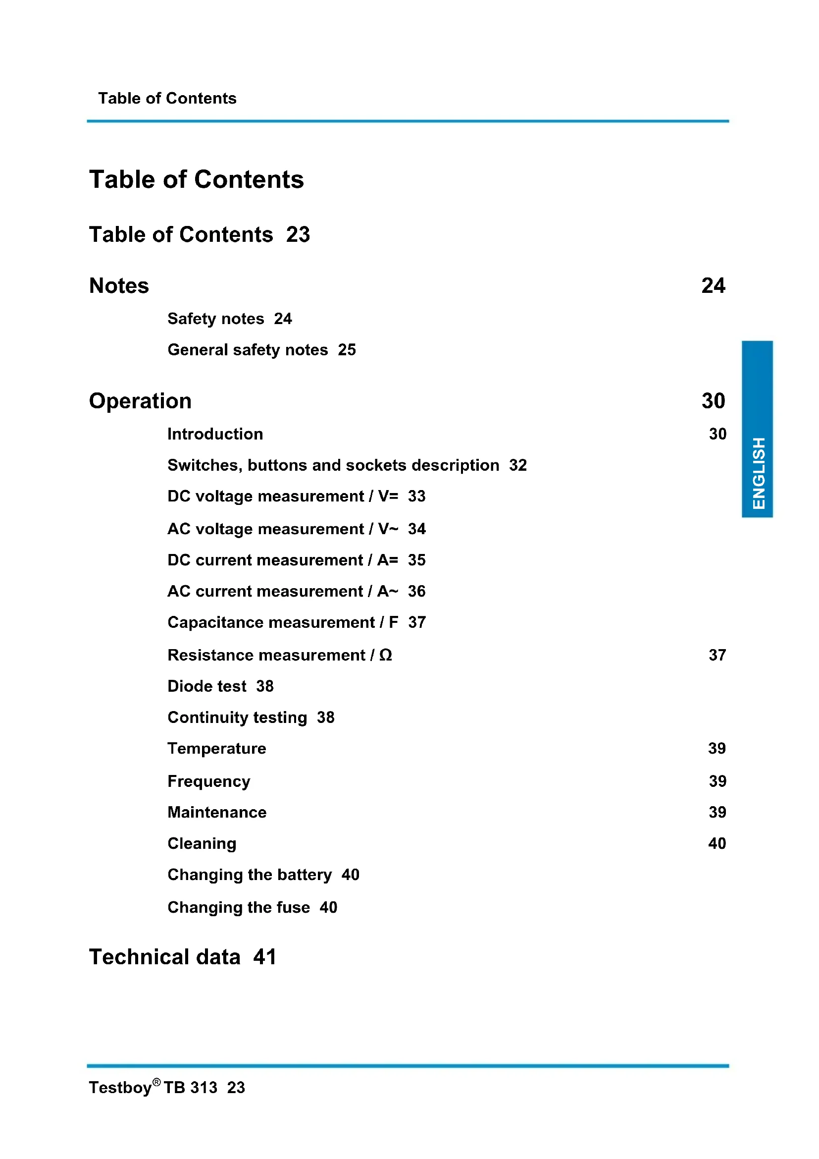
Table of Contents 23
Notes 24
Safety notes 24
General safety notes 25
Operation 30
Introduction 30
Switches, buttons and sockets description 32
DC voltage measurement / V= 33
AC voltage measurement / V~ 34
DC current measurement / A= 35
AC current measurement / A~ 36
Capacitance measurement / F 37
Resistance measurement / Ω 37
Diode test 38
Continuity testing 38
Temperature 39
Frequency 39
39
Cleaning 40
Changing the battery 40
Changing the fuse 40
Technical data 41
Notes
Safety notes

WARNING
An additional source of danger is posed my mechanical parts which can cause severe personal injury.
Objects can also be damaged (e.g., the instrument itself can be damaged).
WARNING
An electric shock can result in death or severe injury. It can also lead to property damage and damage to this instrument.
WARNING
Never point the laser beam directly or indirectly (on reflective surfaces) towards the eyes. Laser radiation can cause irreparable damage to the eyes. You must first deactivate the laser beam when measuring close to people.
General safety notes

WARNING
Unauthorized changes or modifications of the instrument are forbidden – such changes put the approval (CE) and safety of the instrument at risk. In order to operate the instrument safely, you must always observe the safety instructions, warnings and the information in the "Proper and Intended Use" Chapter.

WARNING
Please observe the following information before using the instrument:
Do not operate the instrument in the proximity of electrical welders, induction heaters and other electromagnetic fields.
After an abrupt temperature fluctuation, the instrument should be allowed to adjust to the new temperature for about 30 minutes before using it. This helps to stabilize the IR sensor.
Do not expose the instrument to high temperatures for a long period of time.
Avoid dusty and humid surroundings.
Measurement instruments and their accessories are not toys. Children should never be allowed access to them!
In industrial institutions, you must follow the accident prevention regulations for electrical facilities and equipment, as established by your employer's liability insurance organization.

Please observe the following five safety rules:
1 Disconnect.
2 Ensure that the instrument cannot be turned back on again.
3 Ensure isolation from the main supply voltage (check that there is no voltage on both poles).
4 Earth and short-circuit.
5 Cover neighbouring parts that are under live electrical load.
Proper and intended use
This instrument is intended for use in applications described in the operation manual only. Any other usage is considered improper and non-approved usage and can result in accidents or the destruction of the instrument. Any misuse will result in the expiry of all guarantee and warranty claims on the part of the operator against the manufacturer.

Remove the batteries during longer periods of inactivity in order to avoid damaging the instrument.

We assume no liability for damages to property or personal injury caused by improper handling or failure to observe safety instructions. Any warranty claim expires in such cases. An exclamation mark in a triangle indicates safety notices in the operating instructions. Read the instructions completely before beginning the initial commissioning. This instrument is CE approved and thus fulfils the required guidelines.
All rights reserved to alter specifications without prior notice © Testboy GmbH, Germany.
Disclaimer and exclusion of liability

The warranty claim expires in cases of damages caused by failure to observe the instruction! We assume no liability for any resulting damage!
Testboy is not responsible for damage resulting from:
failure to observe the instructions,
changes in the product that have not been approved by Testboy,
the use of replacement parts that have not been approved or manufactured by Testboy,
the use of alcohol, drugs or medication.
Correctness of the operating instructions
These operating instructions have been created with due care and attention. No claim is made nor guarantee given that the data, illustrations and drawings are complete or correct. All rights are reserved in regards to changes, print failures and errors.
Disposal
For Testboy customers: Purchasing our product gives you the opportunity to return the instrument to collection points for waste electrical equipment at the end of its lifespan.
The EU Directive 2002/96/EC (WEEE) regulates the return and recycling of waste electrical and electronics equipment. As of 13/08/2005, manufacturers of electrical and electronics equipment are obliged to take back and recycle any electrical devices sold after this date for no charge. After that date, electrical devices must not be disposed of through the "normal" waste disposal channels. Electrical devices must be disposed of and recycled separately. All devices that fall under this directive must feature this logo.
Disposing of used batteries
As an end user, you are legally obliged (by the relevant laws concerning battery disposal) to return all used batteries. Disposal with normal household waste is prohibited!
Contaminant-laden batteries are labelled with the adjacent symbol which indicates the prohibition of disposal with normal household waste.
The abbreviations used for heavy metals are: Cd = Cadmium, Hg = mercury, Pb = lead.
You can return your used batteries for no charge to collection points in your community or everywhere where batteries are sold!
Five year warranty
Testboy instruments are subject to strict quality control standards. The instrument is covered by a warranty for a period of five years against malfunctions during the course of your daily work (valid only with invoice). We will repair production or material defects free of charge upon return if these have not been caused by misuse or abuse and if the instrument has not been opened. Damage resulting from a fall or improper handling is excluded from the warranty.
Please contact:
Testboy GmbH Tel: 0049 (0)4441 / 89112-10
Electrical Engineering Works Fax: 0049 (0)4441 / 84536
Certificate of quality
All aspects of the activities carried out by Testboy GmbH relating to quality during the manufacturing process are monitored permanently within the framework of a Quality Management System. Furthermore, Testboy GmbH confirms that the testing equipment and instruments used during the calibration process are subject to a permanent inspection process.
Declaration of Conformity
This product fulfils the specifications contained in the Low Voltage Directive 2006/95/EC and EMC Directive 2004/108/EC.
Operation
Introduction
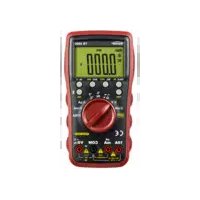
The Testboy® TB 313 is a general purpose Multimeter. This measuring instrument has been manufactured to the latest safety specifications, and guarantees safe and reliable use. The multimeter is a valuable aid for all standard measurement tasks in trade and industrial applications as well as for the hobby electrician interested in electronics.
Included in delivery
Multimeter TB 313
Safety testing leads CAT III 600 V
Operating instructions
Holster
Temperature probe
Safety precautions
The TB 313 left the factory in proper and safe working order. In order to maintain this condition, the user must observe the safety notes contained in this manual.

CAUTION!
Use only the enclosed safety measurement leads or equivalent measurement leads that meet the correct measuring category CAT III 600 V.
In order to avoid an electrical shock hazard you must observe the specified precautionary measures when working with voltages greater than 120V (60 V) DC or 50 V (25 V) eff AC. These values represent the specified limits of safe-to-touch voltages in accordance with DIN VDE (values given in brackets apply to medical or agricultural applications).
Before taking each measurement, ensure that the test leads and the measuring instrument are in a flawless condition.
The test leads and test probes must only be handled using the isolated grips. Avoid touching the tips of the test probes under all circumstances.

The test instrument must only be used for the specified measurement range.
According to the standard EN 61010-1 the following measurement categories are defined:
Measurement Category CAT II
Measurements on circuits that are electrically connected directly to the network, via plugs in the home, office and laboratory.
Measurement Category CAT III
Measurements on the building installations: Fixed consumer units, distributor connection, equipment fitted permanently to the distributor.
Measurement Category CAT IV
Measurements at the source of the low voltage installation: Meter, primary surge protection, main connection.
Switches, buttons and sockets description
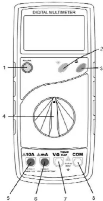
(1) ON/OFF switch
The device is turned on and off using the "POWER" push-button switch.
(2) Lighting switch
Press this button to turn the torch function on and off.
(3) Memory log button (H)
Press this button to store the actual measurement value.
(4) Measuring function selector switch
Use the rotary selector switch to select the various measurement modes.
(5) 10 A socket (left)
The 10 A socket must be used for current measurements above 200mA .
(6) mA socket
For current measurements up to 200mA
(7) Input socket V/Ω/TEMP/CAP
Red test lead for all types of signals supported by the instrument.
(8) Ground socket
Black test lead for all types of signals supported by the instrument.
DC voltage measurement / V=
Use the selector switch to set the appropriate range. Insert the black test lead into the 'COM' socket and the red test lead into the V/Ω/TEMP/CAP socket. Using the test probes, touch the test points of the test object. Read measurement value on the display. The polarity of the voltage will also be displayed.
DC voltage
| Measurement range | Resolution | Accuracy |
| 200 mV 0.1 mV | ± 0.5 % of reading + 1 digits | |
| 2 V 0.001 V | ± 0.5 % of reading + 3 digits | |
| 20 V 0.01 V | ||
| 200 V 0.1 V | ||
| 600 V 1 V | ± 0.8 % of reading + 3 digits |
-Input resistance: 10 MΩ
Max. input voltage: 600 V DC
AC voltage measurement / V~
Use the selector switch to set the appropriate range. Insert the black test lead into the 'COM' socket and the red test lead into the V/Ω/TEMP/CAP socket. Using the test probes, touch the test points of the test object. Read measurement value on the display.
AC voltage
Measurement range Resolution Accuracy
| 200 mV 1 mV ± 1.2 % of reading + 5 digits | |
| 2 V 0.001 V | |
| 20 V 0.01 V | |
| 200 V 0.1 V | |
| 600 V 1 V ± 1.2 % of reading + 5 digits | |
-Input resistance: 10 MΩ
Max. input voltage range of 200mV to 250V
Max. input voltage: 600 V AC RMS, frequency range: 40-400 Hz
DC current measurement / A=
Use the selector switch to set the appropriate range. Connect the black test lead into the "COM" socket, and the red test lead with the mA / 10A socket (the appropriate socket opens automatically depending on the measuring range). Using the test probes, touch the test points of the test object. Read measurement value on the display. The current direction is indicated by the sign.

You must use the '10 A' socket when measuring currents above 200mA .
Direct current
Measurement range Resolution Accuracy
| 2 mA 1 μA ± 1.0 % of reading + 3 digits |
| 20 mA 0.01 mA ± 1.0 % of reading + 3 digits |
| 200 mA 0.1 mA ± 1.5 % of reading + 5 digits |
| 10 A* 0.01 A ± 2.0 % of reading + 10 digits |
Overload protection: mA range is protected with a 200 mA self-resetting fuse.
-10A range is protected with F 10 A / 1000 V.
-In the 10A range observe the maximum operating times!

*To protect against overheating, measurements should not be taken for more than 10 seconds. Following this the device should be allowed to cool down for at least 15 minutes.
AC current measurement / A~
Use the selector switch to set the appropriate range. Connect the black test lead into the "COM" socket, and the red test lead with the mA / 10A socket (the appropriate socket opens automatically depending on the measuring range). Using the test probes, touch the test points of the test object. Read measurement value on the display.

You must use the '10 A' socket when measuring currents above 200 mA.
Alternating current
Measurement range Resolution Accuracy
2 mA 1 μA ± 1.2 % of reading + 5 digits
200 mA 0.1 mA ± 2.0 % of reading + 5 digits
10 A* 0.01 A ± 3.0 % of reading + 10 digits
Overload protection: mA range is protected with a 200 mA self-resetting fuse.
-10A range is protected with F 10 A / 1000 V.
-In the 10A range observe the maximum operating times!
-Frequency range: 40-400 Hz

*To protect against overheating, measurements should not be taken for more than 10 seconds. Following this the device should be allowed to cool down for at least 15 minutes.
Capacitance measurement / F
Use the selector switch to set the appropriate range. Insert the black test lead into the 'COM' socket and the red test lead into the V/Ω/TEMP/CAP socket. Using the test probes, touch the test points of the test object. Read measurement value on the display.
Measurement range Resolution Accuracy
| 2 nF 1 pF | ± 4 % + 3 digits | |
| 20 nF 10 pF | ||
| 200 nF 0.1 nF | ||
| 2 μF 1 nF | ||
| 20 nF 10 nF |

Discharge the capacitors before every measurement.
Resistance measurement / Ω
Use the selector switch to set the appropriate range. Insert the black test lead into the 'COM' socket and the red test lead into the V/Ω/TEMP/CAP socket. Using the test probes, touch the test points of the test object. Read measurement value on the display.
Measurement range Resolution Accuracy
| 200 Ω | 0.1 Ω | ± 1 % + 5 digits |
| 2 kΩ | 1 Ω | ± 1 % + 5 digits |
| 20 kΩ | 10 Ω | |
| 200 kΩ | 100 Ω | |
| 2 MΩ | 1 kΩ | |
| 20 MΩ | 0.01 MΩ | ± 1.8 % + 5 digits |
-Measuring voltage: 0.25 V.
Diode test
With the selector switch set to [ / ) . Insert the black test lead into the 'COM' socket and the red test lead into the V/Ω/TEMP/CAP socket. Using the test probes, touch the test points of the test object. Red test lead = anode, black test lead = cathode. The forward voltage drop is displayed.
Measurement range
Resolution
Display

1 mV Forward voltage
-Forward current: approx. 25 A , reverse voltage: approx. 2.8V .
Continuity testing
With the selector switch set to " + / 0 ). Insert the black test lead into the 'COM' socket and the red test lead into the V/Ω/TEMP/CAP socket. Using the test probes, touch the test points of the test circuit. An acoustic signal is emitted if a resistance under 70 is measured.

Important: Isolate from the power supply and discharge capacitors in the circuit to be measured.
Measurement range Function
。)
The integrated buzzer signals up to a resistance of 70
-Measuring voltage: approx. 2.8 V.
Temperature
Set the selector switch to "TEMP / °C". Place the supplied temperature probe into the sockets "COM" and V/Ω/TEMP/CAP. Touch the object to be measured with the measuring tip. Read measurement value on the display.
Measurement range Resolution Accuracy
-20 to 0^ ± 5% + 5 digits
0 to 400^ ± 2% + 3 digits
1°C
400 to 1000 °C
± 1% +3 digits
Frequency
Set the selector switch to "Hz". Insert the black test lead into the 'COM' socket and the red test lead into the V/Ω/TEMP/CAP socket. Using the test probes, touch the test points of the test circuit. Read measurement value on the display.
Measurement range Resolution Accuracy
20 kHz 10 Hz ± 1.5 % + 10 digits
-Sensitivity: 200mV
-Max. input voltage 10 Vrms
Maintenance
The instrument does not require special maintenance when used as specified in this operation manual.
Cleaning
Use a damp cloth and mild household cleaning agent to clean the instrument should it become soiled through daily use. Never use aggressive cleaning agents or solvents to clean the instrument.
Changing the battery
Change the battery when the battery symbol is displayed. Remove the test leads from the measuring instrument before changing the battery or fuse! Remove the two screws on the rear of the instrument, open the battery compartment and remove the used batteries. Insert new battery (1 x 9 V Block 6F22). Replace battery compartment cover and screw tight.

Only use the specified batteries!
Do not dispose of batteries in normal household rubbish! Observe statutory regulations pertaining to disposal!
Changing the fuse
When changing the fuse, remove the measurement leads from the device and remove the screws on the rear of the device (two at the bottom, one at the top). Carefully remove the rear of the housing and replace the fuse with fuse of the same type (Fuse F 10 A / 1000 V). Replace screws and screw tight.
The F200 mA fuse is self-resetting and therefore maintenance free.

Only use the specified fuse!
Technical data
The accuracy relates to 1 year used in temperatures between 18^ - 28^ and 75% relative humidity. Further calibration is also offered.
Max. voltage between the connection socket and ground:
600 V AC / DC
Fuses F 200 mA self-resetting (maintenance free)
F 10 A 1000 V quick-blow
Max. operating height: 2000 m above MSL
Height of display: 37mm LCD
Display Max. 1999 (3½)
Polarity indicator Automatic
Overrange indicator: "1" is displayed
Sampling rate Approx. 0.4 sec.
Low battery status: Battery symbol is displayed
Power supply 1 × 9 ~V block battery
Operating temperature 0^ to 40^
Storage temperature -10 °C to 50 °C
Dimensions 191 × 82 × 37 ~mm (without holster)
200 × 89 × 38 ~mm (with holster)
Weight
280 g incl. battery
Category
CAT III 600 V
Sommaire
Sommaire 43
Remarques 44
(1) Interruptor ON/OFF
(1) Interruptor ON/OFF