Steel Classic - Bike Puky - Free user manual and instructions
Find the device manual for free Steel Classic Puky in PDF.
| Product type | Children's bike |
| Brand | Puky |
| Model | Steel Classic |
| Category | Bike |
| Weight (approximate) | Approximately 12 kg |
| Maximum load (bike + rider + luggage) | 60 kg |
| Adjustable saddle height | From 45 cm (model Z2/ZL12) to 53 cm (Z8/ZL18) minimum height; minimum insertion depth 65 mm |
| Brakes | Front brake Cantilever or V-Brake depending on model; rear coaster brake on some models |
| Tires | Pressure indicated on tire sidewall; check regularly |
| Transmission | Chain with adjustable tension; some models with 3 speeds (gearbox) |
| Stabilizers | Included for learning; remove after learning period |
| Main functions | Learning to ride a bike; use on consolidated paths off public roads |
| Maintenance and cleaning | Clean with eco-friendly products; oil the chain regularly; protect from salt and moisture; do not use a pressure washer |
| Safety | Wear a helmet; check brakes, chain tension, tire pressure; do not use on public roads; parental supervision required |
| Spare parts and repairability | Original spare parts available from PUKY dealer; wear parts: tires, inner tubes, rims, brake cables, linings, chain, chainrings, grips |
| Warranty | Legal warranty against hidden defects; excludes normal wear and improper use |
Frequently Asked Questions - Steel Classic Puky
User questions about Steel Classic Puky
0 question about this device. Answer the ones you know or ask your own.
Ask a new question about this device
Download the instructions for your Bike in PDF format for free! Find your manual Steel Classic - Puky and take your electronic device back in hand. On this page are published all the documents necessary for the use of your device. Steel Classic by Puky.
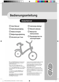
USER MANUAL Steel Classic Puky
Please read carefully before use of the childrens' bicycle and retain in for further use.
(VR 12 Nm, HR 10 Nm)*
Pedale
leicht drehbar

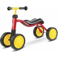
Congratulations on the purchase of this PUKY play bicycle. You have acquired a quality product, which is certain to bring great joy. This User Manual contains information regarding the assembly, safe operation and maintenance of this new bicycle. Should you have any questions or problems, please contact your dealer or contact us via our website: www.puky.de.
2. Parental responsibility
Risks during play are, for the most part, excluded when used in accordance with the intended purpose. However, please take into consideration that unforeseen situations and hazards may occur as a result of the natural need for movement and the temperament of young children and adolescents for which the manufacturer cannot be held liable. For this reason, instruct children and adolescents in the correct bicycle conduct whilst supervising them. At the same time, also draw their attention to potential dangers.
3. User notes
The play bicycle is not suitable for sporting activities (e.g. jumps). The bicycle may only be used on paved paths and roads without obstacles. The bicycle is not suitable for jumps, tricks or cross-country use.
When children are using the bicycle, it may not be ridden in the vicinity of stairs, slopes, steep terrain, swimming pools or other bodies of water. Stairs in the vicinity must be secured in such a way to prevent children from riding up or down them on their bicycle.
The play bicycle may only be used in suitable areas and away from public roads. The bicycle does not comply with the requirements of German Road Traffic Regulations (StVZO) and may not be used on public roads. The relevant applicable national legal requirements are to be observed.
The permissible total weight for this bike (bike + rider + baggage) is 60kg .
The load that may be placed on the luggage rack will depend on the version of the rack (see the embossing on the rack). For road safety reasons, we do not recommend using the rack of a play vehicle for carrying loads. Only the serial installed racks may be used.
It is necessary to wear suitable clothing and closed shoes. PUKY recommends wearing a safety helmet (see PUKY Accessories).
The bicycle is not suitable for mounting a child seat. Pay attention to potential trap hazards when using and maintaining.
Play bicycle
Mount supporting wheels in a secure and form-fitting manner to the rear when required as a learning aid (to maintain balance). The use of support wheels is only permitted during the course of a brief learning period, since with increased practice the support wheels may apply uncontrolled forces to the frame.
Please pay attention to the reduced effect of the brakes on the front wheel when it is wet.
Sudden, forceful braking with the rim brake should be avoided since the behaviour of the vehicle may suddenly change as a result which may end in a fall.
On long slopes, long periods of braking with the back pedal brake are to be avoided (excess heat to the back pedal brake nave).
The valve caps must be firmly tightened and kept out of reach of children (risk of choking). Subsequent additions or modifications to the bicycle (especially the braking systems) will change the behaviour of the vehicle and may pose a risk.
Children's bike
4. Unpacking and scope of delivery
Do not use any sharp objects when opening the packaging and removing protective material. If you were to do so, you may damage the paint or parts of the bike.
Keep all packaging material out of reach of children.
- Remove all parts from the packaging.
- Remove the protective material.
- Examine the package for completeness and proper condition. If anything is missing, please contact your dealer before you continue to assemble the bike.
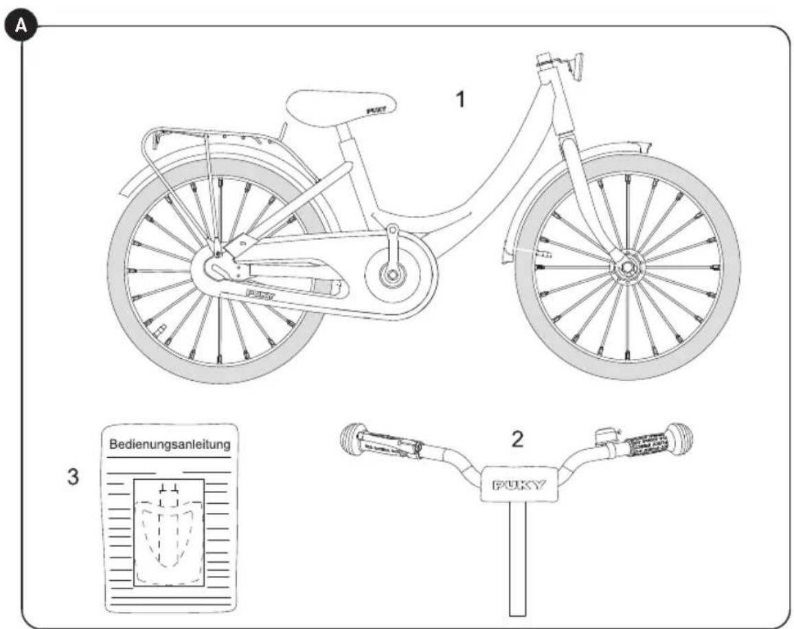
The delivery consists of (Figure A):
- Bike preassembled
- Handlebar preassembled
- Pedals and User Manual in a plastic bag, for 3-gear models: Additional gear stick
5. Assembly and first use
Prepare for use by adjusting to the height of the child. The saddle is to be set so that at least the toes, preferably the ball of the foot, reach the ground in order to ensure balance can be achieved when at a standstill. In doing so, the marking showing the minimum insertion depth on the saddle post into the frame tube must be observed. For more information, see below.
The handlebar, hand brake lever and bell must be easy for the child to reach from the set saddle position.
In doing so, the marking showing the minimum insertion depth of the handlebar shaft must be observed. After adjusting the handlebar, tighten the clamping screws firmly. Use the following safety checklist to check the bicycle before using.
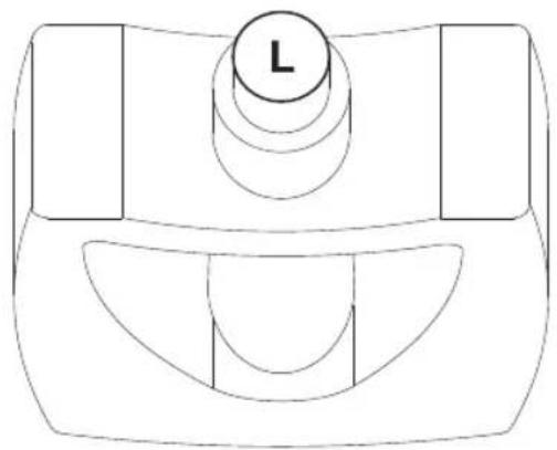
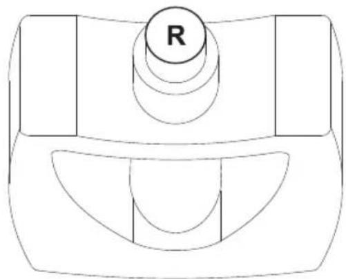
When mounting the pedals, observe the right and left threads (labelled on the pedal axis with an R or L in the vicinity of the thread).
The images for the assembly instructions can be found on the last pages of this manual.
After assembly, please conduct a safety check in accordance with the safety checklist!
During assembly, please note that some parts, such as pedal thread and clamping cone are lubricated.
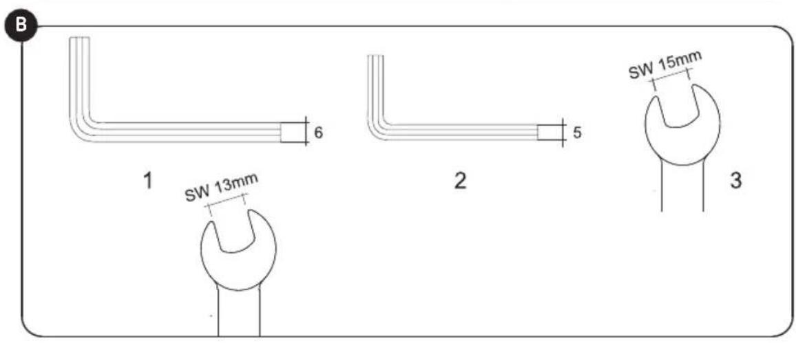
You will need the following tools for assembly (Figure B):
- 6 mm Allen key (ZL models) or a 13 mm spanner (Z models)
- 5 mm Allen key (only for ZL 18-3 models)
- 15 mm spanner
- Crosstip screwdriver
The tools are not part of the scope of delivery.
Assembly must be carried out with great caution and by an adult, to avoid any potential subsequent accidents or injuries. Please take your time when assembling the bike. In some cases, it is necessary to tighten screws with a prescribed torque. The torque value is stated in Newton metres (e.g. 2 Nm). If the torque with which a screw is tightened is too low, the connection may still be too loose and therefore unsafe. If the torque is too high, screws and other parts may be damaged or destroyed. Please contact your dealer or a workshop if you have any questions.
First remove the plastic protective caps from the cap nuts of the front and rear axle as well as from the cantilever brakes at the front. Also remove the plastic foil which has been used to protect the cranks.
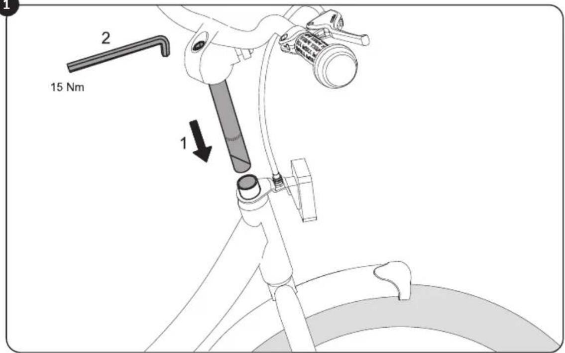
Remove the handlebar padding from the handlebar and unscrew (with just a few rotations) the underlying screw at the stem with the aid of a 6 mm Allen key (ZL models) or a 13 mm spanner (Z models). Now you can remove the plastic cover that protects the clamping cone at the lower end of the stem shaft.
Figure 1: Insert the handlebar into the steer tube (1). If this proves to be difficult, unscrew the handlebar a bit further. Adjust the handlebar to the desired height, align at right angles to the front wheel and lock it by pulling the screw at the stem (2) with the aid of a 6mm Allen key (ZL models) or a 13mm spanner (Z model) (15 Nm).
Please pay attention to the marking of the minimum insertion depth of the stem shaft. Now reattach the handlebar padding back onto the handlebar.
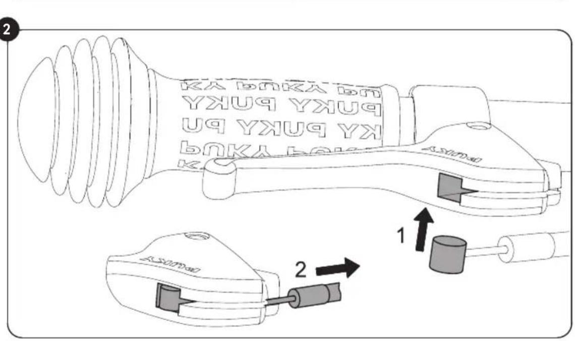
Figure 2: Take the loose end of the brake cable and insert the wedge into the predefined recess on the brake handle (1). Then, carefully pull the outer cover of the brake cable to engage the end stop into the adjustment screw of the brake handle (2).
When assembling the brake cable, please make sure that the knurled screw of the brake cable is situated straight in the holder of the front light. Otherwise, the brakes cannot be assembled correctly.
Setting the handlebar height for models with ahead stem:
The handlebar has been set at the factory to the highest position, thus, all spacers are located under the stem. If required, remove the stem and adjust the spacers to lower the handlebar height.
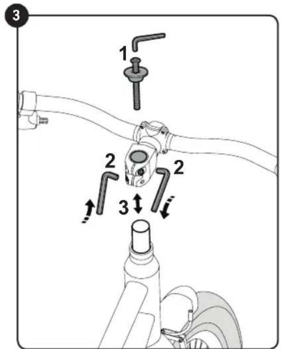
Figure 3: First undo and remove the ahead cap (1). Then undo the two steerer tube clamping screws (2). Now the stem can be removed from the steerer tube (3). Now set the handle
bar height according to requirement. Possible positions are:
- All spacers located under the stem (highest handlebar position, set at the factory)
- Spacers over the stem and under (medium handlebar position)
All spacers above the stem (lowest handlebar position)
No spacers may be removed!
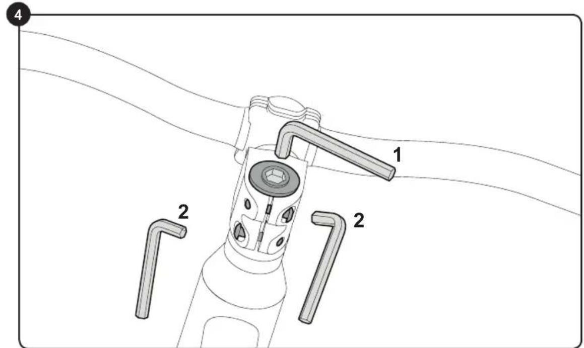
Figure 4: After rearranging the spacers, fit the ahead cap again, align the handlebars to be straight in the direction of travel and set the play of the control bearing correctly. To do this, use the setting screw in the ahead cap (1). Correct setting: The handlebars must be easy to turn without play in the control bearing.
Now tighten up the steerer tube clamping screws of the stem with the correct torque (2).
The torque for the clamping of the stem on the steerer tube shaft: 5-6 Nm. Make sure that the stem is firmly mounted to the steerer tube and cannot rotate.
Adjusting the brakes (Cantilever):
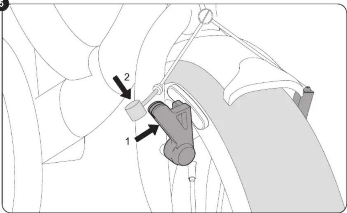
Figure 5: On the front wheel, press the right cantilever brake in the direction of the rim (1). Now you can insert the wedge of the brake cable into the predefined recess of the brake (2). If this is not possible, reduce the tension of the brake cable at the tensioning screw of the left brake arm in the direction of travel (see Figure 6 / Position 2) and then tighten the tensioning screw again.
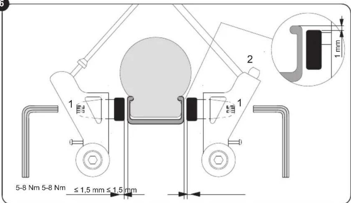
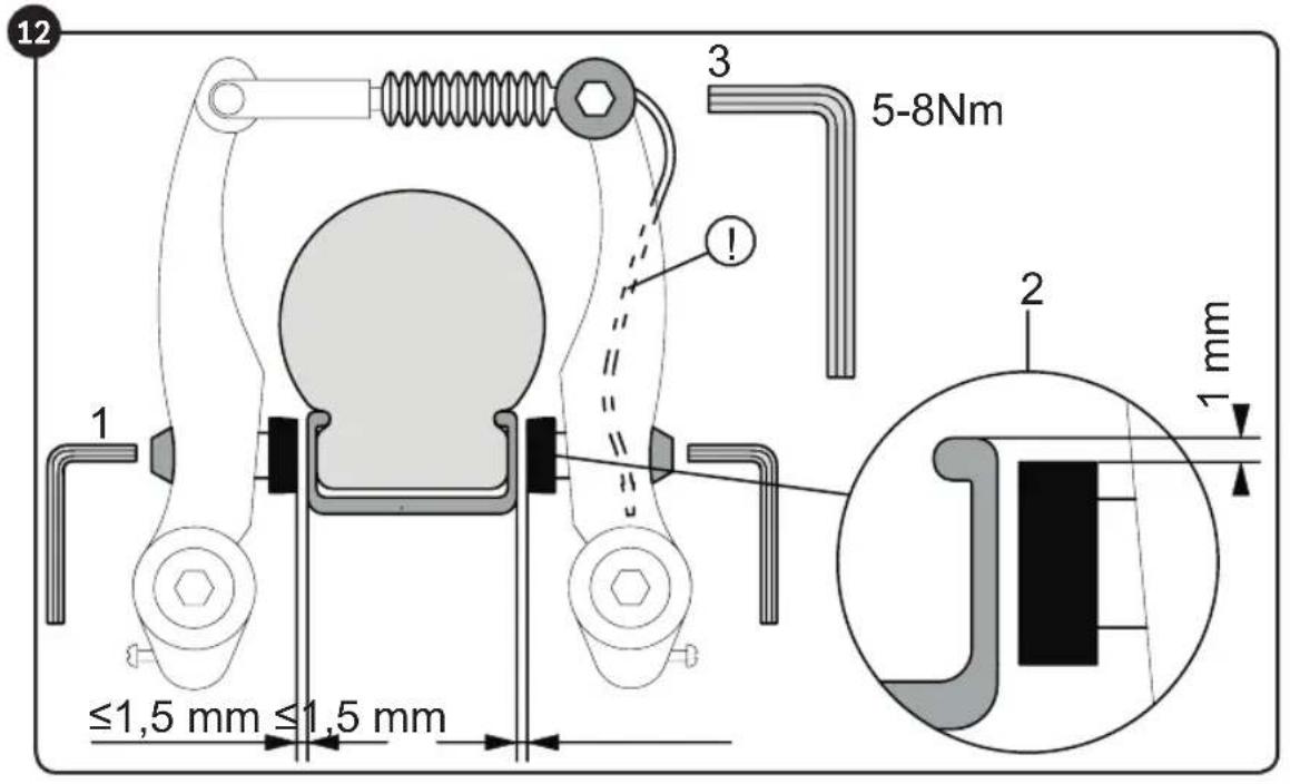
Figure 6: Make sure that the brake pads are parallel to each other and that they are properly aligned with the rim. This means that the brake pads should rest 1mm below the top edge of the rim.
If these settings are not correct, loosen the fastening nut of the brake pad (1) with a 5mm
Children's bike
Allen key and align as described above. To do so, pull the brake lever and re-tighten the fastening nut (5-8 Nm).
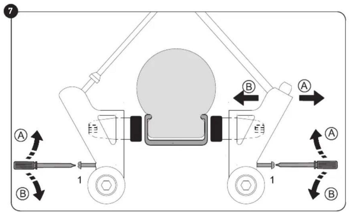
Figure 7: Rotating the adjustment screw enables you to now centre the brake arms, i.e. the distance from the brake pad < - > rim should be identical both on the right and the left. You will need a crosstip screwdriver for this. By turning the screw in, you move the appropriate brake arm away from the rim, turning the screw out moves the screw towards the rim.
It is important that the brake levers are actuated several times so that the tension of the brake arms is evenly distributed to both sides and the settings take effect. The brake/rim contact must be identical on both sides.
Again Figure 6:
Brake cable tension is adjusted at the anchor nut (2) so that each brake pad maintains a distance of 1.5mm to the rim. If an adjustment needs to be made, the protruding wire end should then be refastened to the brake.
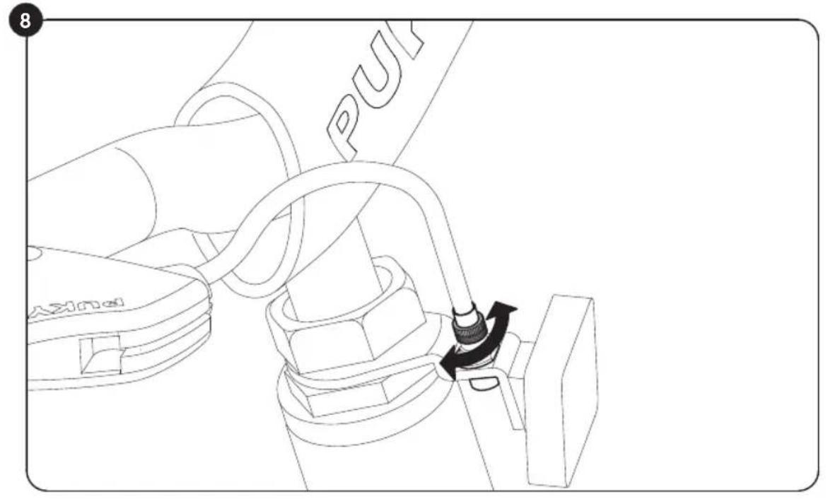
Figure 8: With a slight degree of wear to the brake blocks, you can remove them by unscrewing the knurled screw above the front reflector and position both blocks closer to the rim. Adjust the screw so that the each brake pad is set at a distance of approximately 1.5cm from the rim.
Before each journey, please check whether the brakes are functioning properly. If, during the course of the use of the product, renewed adjustment of the brakes is required, please follow the steps detailed above.
Adjusting the brakes:
The bicycle has two calliper brakes. The left brake lever operates the brake on the front wheel, the right brake lever operates the brake on the rear wheel. Depending on the
model, the bicycle may also have a back pedal brake for the rear wheel.
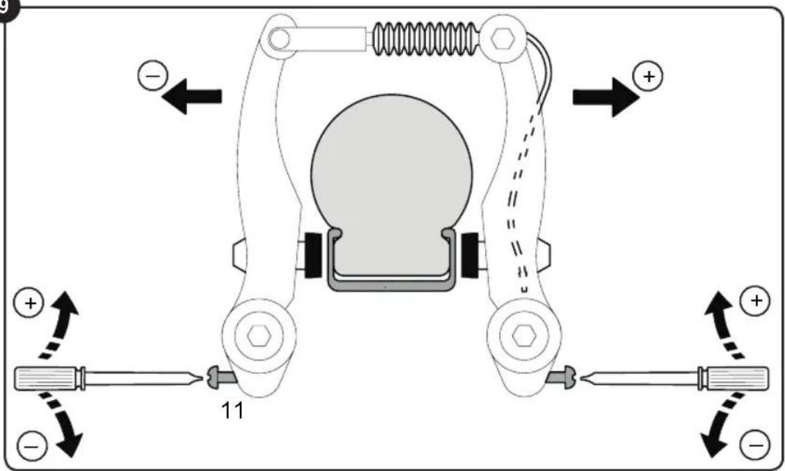
Figure 9: Centre the brake arms (1) by turning the adjusting screw. The gap between the brake pad < - > rim should be identical on both right and left and the contact between brake pad/rim should be applied simultaneously on both sides when you brake.
You will need a cross-headed screwdriver. By turning the screw in, you move the appropriate brake arm away from the rim, turning the screw out moves the screw towards the rim.
It is important that the brake levers are actuated several times so that the tension of the brake arms is evenly distributed to both sides and the settings take effect.
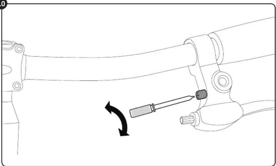
Figure 10: The handle distance (distance of brake lever to handlebar) can be adjusted individually using an cross-headed screwdriver on the brake handle. Please remember that braking must take effect before the brake lever reaches the handlebar!
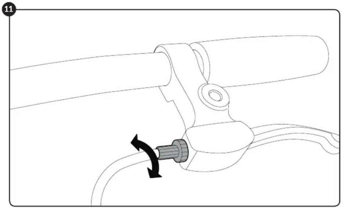
Figure 11: The tension can be set on the brake handle using the knurled screw.
The brake is set correctly if the brake pads are all approximately 1.5mm from the rims.
Replacing the brake pads
Figure 12: Undo the fastening nut of the brake pad using an Allen key sized 5mm (1) and replace the brake pads.
This means that the brake pads should rest 1 mm below the top edge of the rim (2). If these settings are not correct, loosen the fastening nut of the brake pad (1) with a 5mm Allen key and align as described above. To do so, pull the brake lever and re-tighten the fastening nut (5-8 Nm).
The tension is to be set so that the brake pads are all approximately 1.5mm from the rims. If subsequent adjustment is necessary, undo the
tensioning screw (3) and adjust the tension (tighten the tensioning screw back up using 6-8 Nm!) or carry out the step described in Figure 11.
Setting the chain tension (models with gear hub) The chain should have a vertical play of approximately 1.5cm . The setting of the chain tension is carried out as follows: Figure 9: Undo both wheel nuts of the rear wheel. Adjust the chain tension by sliding the rear wheel at the dropout. Then tighten the wheel nuts back up again (torque 20Nm ). For models with derailleur gears, the chain tension is regulated via the gears.
Attention should be paid to ensure that the correct chain length is selected when replacing the chain.
Figure 13: Please note that one pedal is equipped with a right-handed thread (for the right-handed driving direction) and the other pedal with a left-handed thread (for the left-handed direction). The pedals are labelled accordingly on the front face of the threaded axle with an "R" and an "L".
Screw the pedals with the aid of a 15mm spanner to the cranks (20Nm) - to do so, turn the Allen key on both sides in the direction of the front wheel.
Setting the seating position
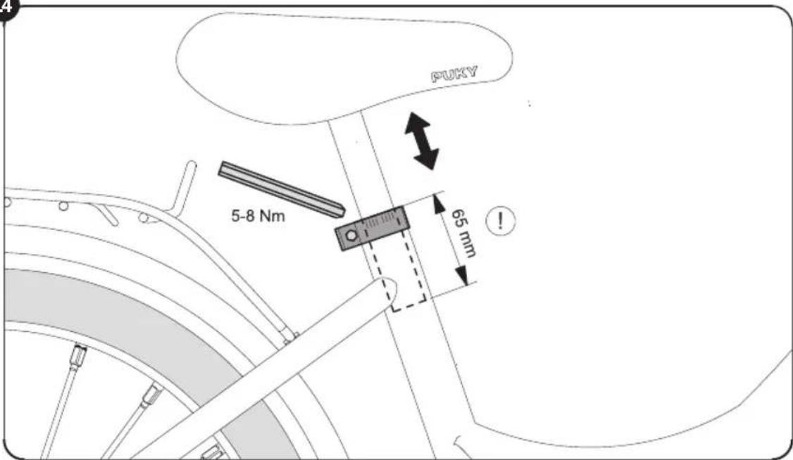
Figure 14: Setting the height of the saddle: The saddle can be pulled out after releasing the saddle clamp with the aid of a 5mm Allen key. Set the saddle so that at least the toes, preferably the ball of the foot, reach the ground in order to ensure balance can be achieved when at a standstill.
Please observe the following principles:
Minimum height of the saddle as follows:
Z2/ZL 12:45 cm
Z6/ZL16:49cm
Z8/ZL18:53cm
Maximum height of the saddle:
The minimum insertion depth of the saddle post is 65mm . There is an appropriate marking on the saddle post (see Figure 8).
Then retighten the saddle clamp (torque 5-8 Nm).
Setting the height of the handlebar: Adjust the seating position so that the child is seated upright and a good overview is ensured. The handlebar, hand brake lever and bell must be easy for the child to reach.
The torque for the clamping of the stem in the fork stem: 15 Nm.
The torque for the clamping of the handlebar in the stem: 12 Nm.
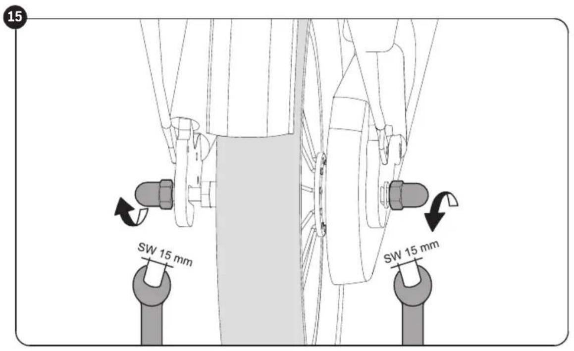
Setting the chain tension
The chain should have a vertical play of approximately 1.5cm . The setting of the chain tension is carried out as follows:
Figure 15: Undo both wheel nuts of the rear wheel
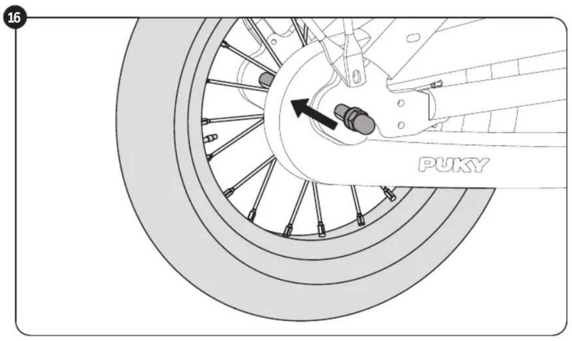
Figure 16: Adjust the chain tension by sliding the rear wheel at the dropout. Then tighten the wheel nuts again (torque 10 Nm)
Children's bike
Setting the gear hub (only for 3-gear models)
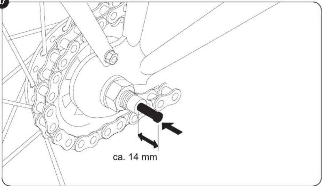
Installation of gear stick
Figure 17: Take the gear stick out of the plastic bag and insert it as far as it will go, along with the black spring, into the right side of the rear axle (in driving direction).
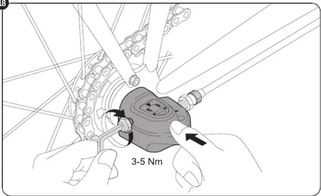
Figure 18: Then you can mount the gearbox onto the rear axle and tighten it with a 5mm Allen key (3-5 Nm.) No further settings need to be made to the gearbox.
If renewed adjustment must be made during the course of product use, proceed as follows:
SET
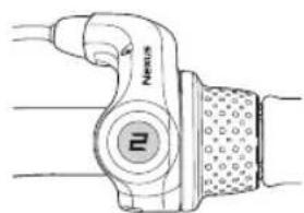
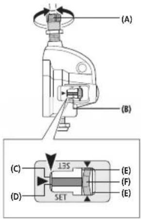
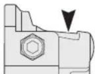
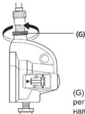
Switch the REVOSHIFT lever to 2. Then rotate the tension adjusting screw (A) in order to align the red line (D) on the push rod at the end (C) of the hub axis.
COMMENT
During the setting process, check both yellow lines from above using the window. Rotate the crank and switch the REVOSHIFT lever from 3 to 1 and then back to 3. Repeat this process two or three times and check to make sure that the gears are changed. Switch the REVOSHIFT lever from 1 to 2 again and make sure that the red line on the push rod at the end of the hub axis is aligned. If this is not the case, you must carry out the setting process again.
After setting switch unit IV secure the tension adjusting screw using the tension adjusting nut (G).
(A) Tension adjusting screw
(B) Push rod
(C) End of hub axis
(D) Red line on push rod
(E) Yellow lines
(F) Yellow section of link
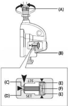
Torque: 1.5 - 2.5 Nm
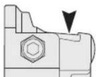

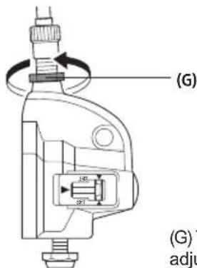
(G) Tension adjusting nut
| Safety checklist | Tyres |
| Saddle | Sufficient profile |
| Firmly secured and cannot be rotated (5-8 Nm)* | Sufficient air pressure (air pressure to be maintained is on the tyre) |
| Minimum insertion depth marking observed | |
| Balls of feet reach the ground | Wheels |
| Handlebar | Aligned |
| Minimum insertion depth observed | Spokes evenly tightened |
| Handlebar shaft tube secured and cannot be rotated (15 Nm)* | Axle nuts firmly tightened (VR 12 Nm, HR 10 Nm)* |
| Handlebar cannot be rotated | Pedals |
| easy to reach, upright seating position | Rotate easily |
| Handles cannot be rotated | Firmly fitted without excess play |
| Handbrakes | Bell |
| Brake lever secure (2 Nm), easily accessible | Clear ring, easily reached |
| Functions perfectly | |
| Brake pad clean, grease-free, positioned correctly | Visual check |
| Back pedal brake | Components without fault and all attached parts, such as protective guards and luggage rack, sufficiently well secured. |
| Function checked | |
| Chain | |
| Chain tension is OK (play approximately 1.5 cm) | |
| Sufficient lubrication | (*Torques of screws in Newton metres) |
| Chain guard is complete |
Children's bike
6. Maintenance and care
If the handbrake lever can be pulled more than half-way to the handlebar before the braking effect takes place, the brake must be adjusted.
The braking surfaces must be clean, grease-free and the brake pads must be parallel to one another.
Worn pads must be replaced immediately! When replacing, make sure you use original pads or ensure that they match the material of the rim at least (e.g. see the label: "Alloy / Alu" for aluminium rims).
Caution in the event of rim wear
Regularly check the state of the rims and pay special attention to the wear groove which surrounds the rim. Consult your specialist workshop in good time (when the groove is almost worn away). Breakage and accident risks!
Pay special attention to ensure that the handlebar and saddle do not rotate!
Check the chain tension and adjust as necessary (if required, by loosening the rear wheel, aligning and tightening again).
Pay attention to the correct air pressure (the prescribed pressure is indicated on the sides of the tyres). Do not repair damaged or deformed parts. Damaged or deformed parts must be replaced. Original replacement parts can be obtained from your PUKY dealer. Spare parts: Tyres (including tubes), rims, brake cable, brake pads, chain, chain rings, handle covers.
All maintenance work requires specialist knowledge and you should consult your dealer for advice. Interested children may 'supervise' but should not do the work themselves.
Cleanliness and corrosion protection
All painted and metallic surfaces can be cleaned and protected using ordinary car care products. Only use environmentally friendly products and never use any aggressive detergents. Regularly oil the chain (chain or universal oil) and clean when necessary.
The flanks of the rims (braking surfaces) must be grease-free!
The vehicle is to be protected from winter salt and long periods of storage in damp spaces (e.g. garage) are to be avoided. If you do store the bicycle in a damp environment, protect the surfaces of unpainted metal parts (screws, nuts etc.) with a suitable surface seal (e.g. spray wax).
Hub and ball bearing should be checked from time to time by a specialist, adjusted and lubricated as required. The vehicle is to be protected from winter salt and long periods of storage in damp spaces (e.g. garage) are to be avoided.
Do not use a pressure washer/power washer to clean the vehicle.
7. Statutory warranty
Statutory warranty covers defects. Damage resulting from improper use, use of force, lack of maintenance, or normal wear and tear, is excluded from such a statutory defect warranty.
Enjoy your travels!
1. Inleiding
2. Foraeldrenes ansvar
Freno a mano saldo (2 Nm), ben accessible
Vymena brdovych oblozeni
(VR 12 Nm, HR 10 Nm)*
Ručni brzda
brzdope paky zafixovany (2 Nm), dobre dostupne
funkce bezporuchová
brzdove oblozeni je ciste, bez tuku, spravne prileha
Pedály
snadno otočné
pevnabezprilisvelkévule
Pedálová brzda
I3MeHeHIO XapAKTePNCtNK DBNXKeHnBEJIOcNPeJa N K NaDeHIO.
Ha dnnnHbix cnyckax cneNyet n36eRaT bIINTeJIbHOrTO TOPMOKeHnC NOMOuBIO neaIbHOrTO TopMo3a (CNbHbI HarpeB CTyNcbl neaIbHOroTopMo3a).
KoJnauKn KnaIaHOB Heo6xOIMO pIOTHO 3aTHyb n He dOnyCKaTb nx nonaHaBn B pyKn DeTei (onacHOCTb npOrNaTbBaHn).YcTaHOBKaDOnOHNHeNbHOrO o6OpUdOBaHn N BHeceHneN3MeHEnB KOHCTpyKcuNo BeNoCInPeDa (npEeBCero, B TopMO3HbIe yCTpOiCTBa) N3MeHArTO erO xOIOBbIe KaueCTBa, YTO CO3daet ONaCHbIe CNTyaQnn.
4. PacnakOBka N KOMNJIeK TIOCTaBKn
He nCnOJb3yIte DnB BCKpItnY yNAKOBKn UyaJIeHn 3aunTHoro MaTePnaJa oCTpbIe npEdMeTb. OHN MOrTy CepBe3HO NOBpeDHT b NAKO-KpaocHoe NOKpItne INI dTeAIN BeNoCInPeJa.
DepKnte IIO6o ynaKOBOHyMaTePnAn nOdaIbWe OT DetEi.
- N3BJIeKInTe BCE DeTaIIN uN3 yNaKOBKn.
- CHIMITE 3auntthbMATEpnaJ.
- PpOBepbTe KOMnIeKTHoCTb NocTaBKn HAnuHne NoBpeKdEHN, NOyueHHbIX npn TpaHCnOpTnpOBke. B cnyae OTCyTCTBna KaNX-JN6o DeTaleN o6paTntEc b K perNoHaJIbHOMy DnIepy, npExKe Yem npOdoJkaTb pa6Oty.
B KOMNNEKT NOCTaBKN BxOaT CneAyoUne KOMNOHeHTbI (pnc.A):
- BénoiéB co6paHHOM coCTOHN
- Pynb B co6paHHOM COCTOHN
- PekannykoBOCTBO no 3KcNpyataunB NOIN3TNNEHOBOM NaKeTe,ДЯ MoJeNe 3 CKOPoCTe: DOnONHHTeJIbHbI KOHTaKTHbI WtnΦT
5. MoTAX K BBOD B 3KcNpyatauH0
OtperyuipoBaTb BeIOcHneI c yueToM poCTa pe6eHa. CeIIO Heo6xOIMMo yCTaHOBnTb TaK, 4TO6blpe6eHOK MOr DoCTaBaTb Do 3eMNI HOCKOM HOn, a eIe IyUHe BceI CTOnOI N TAKIM o6pa3OM COXpAHrTB paBHOBecNE. Ppi 3tOM o6ra3aTeNbHO Heo6xOIMo yHTbIBaTB OTMeTKy MINHMaJIbHO rIy6bHbI NOcaIKN Ha ceIIOpeJKAteJIe B Tpy6Ke KapKaCa CndEhBa. PoIPO6Hee 06 3tOM HIXke.
PyNb, TaKke KaK pbHar pyHoro TOpMo3a N 3BOHOK DOJIKNHbI 6bITb OTpeRyIINPOBaHbI TaK, UTO6bl CnDrau nn pe6eHOK IerKO DoCTabAN Do HxN.
Pn3TOM Heo6xOIMO yuHTbBaTb OTMeKy MNHmAlbHOI rJy6nHbI nocAKn pyJI. NocpepyNipOBKn pyJI 3aTaNHe 3aXMHBte BnHTbl. PepeB BBOOM B 3KcNpyatauHIO npOBepbTe BeJocIneNo cJeDyUcEMy KOHTpoJbHomy CnNCKy 6e30NaChOCTn.
MoHTnpy neaJIH, Heo6xOJIMO yuHTbIaT bJeByIO nII npabyIO pe3b6y (MapKIpOBKa R nII L pAOM c pe3b60n Ha oCn neaJIH).
ΦOTOrpaФи K yka3aHnI M NO MOHTaKy HaxOДЯТС RA Na OcNeIeHIX CTpaHnIaX DaHHORO pyKOBOdCTBa NO 3KcnIpyaTaUIN.
Iocne MOHTaxa npOBepbTe BeJIOcNPeD B COOTBeTCTBmC KOHTpOJIbHbIM CnNcKOM 6e3- onachoctn!
PnMOHTaKe 6paTne BHIMaHHe, YTO HeKOTOpbIe pe3b6ObBte qactn neJaIe n 3aXIMHOro KOHyCa NOKpbITbI CMA3KOi.
MOnTaKa Tpe6yETc CneDyUoUu HCTpyMeHT (Pnc.B):
- TopoBbI JecTnRpaHHbI raeHbI KIOU 6 MM (MoJeN ZL) NIO Bo raeHbI KIOU SW 13 MM (MoJeN Z)
- TopoBbI WeCTnRpaHHbI raeHbI KIOU 5 MM (TolbKO dJa MoJeNe ZL 18-3)
- TaeuHbI KJIIOU SW 15 MM
- Kpctobar OTBeptka
HCTpyMeHT He BXOINT B KOMNJIEKT NOCTABKN.
MOHTAX DOJXEN BbINOJIHrB 3PocIbI YeIOBek, DeINCTByOueHb BHIMATEIbHO, Yo6bl NCKIHOHTb PnCK NOcNeIyUoNIX HeCuaCTHbIX CnyUaEB IIN TpaBM. OTBeIte Ha MOHTAX DoCTaTOOHoe KOINcEBo BPemEH. B HEKOTOpBX MeCTAX Tpe6byTc 3aTARNBaTB BVHTb ONpeJeHHbIM MOMETOM 3aTAAKK. MOMET 3aTAAKKYkA3bBAeTCB HbIoTOH-Metpax (HaNPmep,2 HM). Ecn 3aTAYb BVNT C MehShUM yCNIneM, COeINHeHNE MOKeT OKa3aTbcra CNIuKOM cna6bIM IN HeHaJeXbIM. CNIuKOM 60nbloe ycInne MoKET npVBecTHN K NOBpeXdEHIO n pa3pyWeHNBOBVHTOB IN Dpynx Detanei. Ecn Bbl CyBCTBYeTe Ce6ra HeoCTaTOUHO yBepeHHO, O6paTntEc b K perNoHaJIbHOMy dInepy IIN B MaCTepckyo.
Chayana Heo6xOIMO ChrTb INaCTMaccOBbie 3aunTHbIe KOJnauKHa rnynx raikax nepeHne H3aHHeOcN, a TaKke Ha nepeDnHex TopMO3ax. CnHmTe TaKke P3-NeHky, 3aunuAoUy0 KpNbOoHnbl.
CHMNTe 6Bkpy npI n c NOMOuBTOTOPoBOrO
WecTNrpaHnHO raeyHoro KIOUa 6 MM (MOeJI N Z) IIN RAeHoro KIOUa SW 13 MM (MOeJI N Z) OTBnHTnte Ha HeCKOJIbKO O6OpOTOB BnHT Ha BBInOce pyJ. Tepeb MOxHO ChrTb PnactMacCOByKpBlKy, 3aunuAoUy0 3aKmHOn KOHyC Ha HnKHeM Kpe WeyKn BblHocApyJ.
Pnc.1:HaeneBte pynb Ha pyneBoC stepeh (1).Ecnn OH caINTcra TKeJe,TO 6oJIbwe ocIa6bTe BnHT Ha pyne.YCTAHOBnTE pyNB Ha HyKHyo BbICOTu NOD npMmBIM YrIOM OTHOCHTeNo nepedHro Koneca,3aФнкCpyte B TAKOM noLoXeHH,3aTMyB BnHT Ha BbHOce pyna (2) TOPOBBIM WeCTINrpaHHbIM KIOUOM 6 MM (dIy MoJenZL) n60 raeHbIM KIOUOM SW 13 MM (dIy moJenZ) (15 Hm).
PnTOM CNEIHTe 3a MEKoM MHHMaJIbHOI rny6HbI NOCAkN Ha ueKe BBIHOc pyJr. YCTaHOBtE Ha3ad ObuBky pyJr.
Pnc.2:Bo3bMNTe CBO6OHyB KOHeu TOpMO3Horo TPOcNkA N BCTaBbTe KOHcEbnK B IpeDyCMOTpeHHoe yIpy6JIeHne Ha pyKOaTKe TOpMO3a (1).3aTeM octopoXHO NotHnTe HApxHyIO bOLOUky TOpMO3HOro TPOcNkA, YTObI KOHcEboYnOp 3aФHKcnpOBaJcH a PerynpOBoHOMBnTE pyKOaTKn TOpMO3a (2).
Bo Bpem MoTaxa TopMo3Horo TpOcNka CnE Dnte, UTo6bl BNHT C pUΦJIeHOr fONOBKoI TopM03Horo TpOcNka cnDlEN ToHb B KOHTponope NpeedHero foHapr. B npOTNBOM cnyae He ydaCTc npabINbHo yCTaHOBtB TopMO3.
PerynupOBKa BbICOTbI pyraB MoedJcx C BbHOCOM pyra Ahead:
PyIb yctaHOBnEn Ha 3aOBe B cAMOM BepxHem NIOJKeHN, T.e. BCE npocTaboHbIe KOJIbUHaXoJaTcNOD BbIHOCOM pyJr. Ppr Heo6xoMocTN BblCOTy pyJr MOKHO yMeHbUInTb PyTeM DEmoHTaKa BbIHoca pyJr INpeHaJaKn npocTaboHbIX KoneL.
Pnc.3:Chayana ocna6bTe n CHIMITE KOJNa- yOcAhead (1). 3aTeM ocna6bTe o6a 3axm-HbIX BnHTa pyneBoro cTepxHra (2). Tenepb MoXHO ChTb BbIHoc CpyneBoro cTepxHra (3). Tenepb yCTaHOBITe HxKyIO BBICOTy pyIb. Bo3MOXHbIe NOJoxKeHnI:
BCE npocTaBOUHbIe KOJIbIa HaXOJATcR IOd BblHOCOM (camoe BblCOKOE NOIIOKeHne pyJIa, 3aBoDcKa perynipOBka)
- npoCTaBOHbIe KOJIbIcA BblIe N HIXe BblHOca pyIra (CpeDHee IIOJoxKeHne pyIra)
Bce npocTabeHbkeKolbaHaXoJrTcHaBbIHOCOM (camoe Hn3Koe nOxKeHne pyna)
PpoctaboohbIe KOJIbua ydaanTb HEnb3r!
Pnc.4: Nocne nepehaJn npocTaOuHbIX KOJIeU cHOBA cMOHTnpyIte KOnNaUOK Ahead, ycTAHOBNTe pyJIb nHaNPaBNeHIO dBNKeHn I npMo I npABInbHo OTPeryLnpyIte JIoΦT NOd- WmNHka pyJI. UcNoB3yIte dIra 3tOro peryNPOBOUHb BnHT B KOnNaUKe Ahead (1). Ppa
Дeтскн Велocише
BnIbHa peryIpOBKa:pyIb DoJKeH Ier-KO NOBopauBaTbcra np OTCyTcBnn IIOpTa B NoD- WnIHKe pyJI.
Tenepb 3aTnHte 3axmHbIe BNHTbI pyneBOrO cTePKHa HbHOce C npabINbHbIM MOMENTOM 3aTAAK (2).
Momet 3aTAAKn Dnla 3aXkMa BbIHocpa pyBa pyneBOM CTepkHe:5-6HM.Y6eDntecb,yTO BbHOCpyJa3akpePnHeHa pyNeBOM CTepkHe OT npOBopaunBaHn.
PerylnoBka TopMo3a (Cantilever):
Pnc.5: PnKMMTe npabBn, NO xOdy DnKHeHn, TopMO3HOm MexAHnM npeJHero KOleca K O6o- dy KOleca (1). BcTAbbTe Tenebp KOHcEbnk TopMo3HOro TPOcNkBA npeDyCMOTpeHHoe yrIy6neHne Ha TOpMO3e (2). Ecn 3TO HeBO3MOxHO, YMeHbUHTe HATXKeHHe TOPMO3HOrO TPOcNkHa TaHyUeM 3aXHMHom BnHTe CNeBa B HApPABHeHN DBNXeHn PIIeCa TOpMO3a (cm. Pnc. 6 / no3. 2) n 3aTEM CHOBa KpENKO 3aTAYHtE TReHUsn 3aXHMHO BVHT.
Pnc.6:YIOCTOBepbTecb,TOObeTOPMO3HbIe HAKnAaKn CToR TnapaJIeJIbHO Dpyr DpyrN INx NIOXKeHHe Ha OoDe BbIPOBHeHO.3To 3HaHT, YTO OHn paCNOJoxKeHbI Ha 1 MM HnKe BepXHero Kpaar OoDa.
B cnyae HnnpabnIbHoi peryIinpOBKn OTBnHTnte KpeNEXHyIO raKy TOPMO3HO HAKnAdKn (1) npn NOMOUs TopoBOrO WeCTurpaHHoro KNUOa 5 MM n OtperyIpyTe TAK, KaK ONCaHO Bblwe. HaxMITE TopMO3HO pbIar n CHOba 3akpyTNTe KpeNEXHyIO raKy (5-8HM).
Pnc.7: NOBopauNBa perynpoBOHyB BuHT, Otperynpye npeo TOpMO3a nocepeHne, To eTb, YTO6bl paCCToHHe TOpMO3Ha HaKnJaKa <-> o6oD bIIO OINHAKOBbIM CnpBa + cNeBa. Bam Notpe6byETc KpctOBa OTBeptKa. Pytem BkpyuBAHn BAHT OTOdBHNbTe COOTBEtCTByO-uee npeo TOpMO3a OT o6oDa, BBiBepHyB BuHT Ha o6oJ.
BaxHo, yTo6bI TOPMo3HbIe pByaHn npn 3TOM MHOROKpaTHO HaxkMaJIncb, yTo6bI HaTJKeHne TOPMO3HbIX PIIeH 6blIO OINHaKOBbIM C 06ExCtOpOH, apeYInpOBKa 6blNa 3cFKeKTbHbOH. KacaHne TopMO3rIero 3JemeHTa C 06oDM D0JIHXo IpoNCxoIDNb ODHOBpeMeHHo C 06ExCTOpOH.
Eue pa3 pnc.6:
HaTaeHne TOpMo3HOro TpOca Ha fKnCnpyuOeIraKe (2) DoJNHO 6bITb OTpEryInpObaHo TaKIM o6pa3OM, YTO6bl TOpMo3HbIe HApKaIKn OTCToRIN OT o6Oda npImepHO Ha 1,5 MM. EcJI IN Tpe6yETcIocInpOBKa, To nocJe Hee Heo6xOJIMo CHOBA 3aKpeNtB BepXHNI KOHeU TpOca Ha TOpMO3e.
Pnc.8: PnH He3HaHTeJIbHOM H3HOce TOpMO3- HBIX KOJIOOK Heo6XoDIMO OTBepHyTb BNHT C pIeHoi roJOBKOH aI nepeDnM OtpKaTeJEM, YTO6bl TOPMO3HbIE KOJIOKn C o6Enx CTOpOH nOdo7n 6nKe K o6Oy. OtperynpyTe TOPMO3 TaK, YTO6bl TOPMO3HbIE HaKJaKn OTCTynaNt OTo6Oa np6bn. Ha1,5 MM.
IpeenKaKdoNoe3dko npOBepnTe HaDneJkaUIO pa6Oy TopMo3OB.EcInB xOJe 3cknlyatauNn 13dEINN noTpe6yeTc NOBtOpHAperyNlpOBKa TopMo3a, pnpdepkBaITecb BblweyKa3aHHbIX DeiCTBn.
PerynnpobKa TOpMo3a:
HaBENOCINNEeEcTB DBA TOPMO3a,JeIcCTBYIOUx HA O6oJ.JIeBa pyKOaTKa TOPMO3a npINBOiNT B DeIcTBnE TOPMO3 Ha nepeHem KOIeCe, npabra pyKoRTKa TOPMO3a npINBOiNT B DeIcTBnE TOPMO3 Ha nepeHem KOIece.B 3aBNCMOCTN OT MOeJIHn HA BeLOCINNeDe DOONHNTeNbHO IMeETCR TopMO3 dJaADHeRo KOIeCa,DeIcTBYIOUHn PnObpaTHOM HaxKaTmH Na neJaJIb.
Pnc.9: NOBOPaHBA perynnpoBouhB BnHT, OtperynpyTe cKobI TopMo3a No ceHTpy (1). PacctOHHM MExNy TopMo3HO HAKnAaKOu o6oDM Cnpaba UNcEBA DOJXHbI 6bITb OmHa
KOBbIMN, INPNI TOPMOXKeHIN KOHTaKT TOPMO3HOH NaKlaIcN C O6oDM C O6eNX CTOPOH DOJIKeH npOxCxOaNTb OJHOBpeMeHHo. Bam nOTpe6yeTcR KpctOBaAR OTBepTKa. 3aKpyuHBa BRHT, Bbl OTBOInTE COOTBeCTCBYIOUyIOCKOBy TOPMO3a OT o6oJa, BbIKpyuHBa BNHT — NOBDOInTe ee K o6oMy.
Pn3TOM Baxho HeckoBko pa3 HaaTb Ha pyKoRTKn TOPMo3a, YTO6bl npNXIM CkO6 TOPMo3a 6bl OINHaKObIM C 06eHX CTOpOH n perynpoBka OKa3anacb 3ΦΦeKTHBHOI.
Pnc.10:PaCCTOHaHne Do rpnncbI (MeKdy pykoTKO TOpMo3a npylem) MOxHO INDnBnDyAaBHO HAcTpaNBaTb BNHTOM C BHyTpEHNM UeCTnIrpAHNKoM Ha pykoTKe TOpMo3a. O6paTnteBHMaHHe, YTO TOpMOXeHne DOJNXHO NaHnHaTbCcDo TORO, KaK pyKOaTKa TOpMo3a KOCHTcRpyr!
Pnc.11:HaTaeKeHne MoXHo peYIIpObaTb BnHTOM c PnΦJIeHOI rOIOBko H a pyKoTke TOpMo-3a.
TopMo3 OTperyInpoBaH npaBnIbHo, ecIn TopMo3HbIE HaknaKn OTCToR T O 6Oda npImepHo Ha 1,5 MM.
3aMeHa TopMo3HbIX HaKnlaDOK
Pnc.12:OTBnHTnte KpeNExKHyIO raKy TOPMO3HOH HAKJaDKI npi NOMOUI TopoBOrO IeCTNuRpaHHoro KJIouHa Ha 5 MM (1) n 3aMeHnte TOpM03HbIe HAKJaDKI.
Topmo3HbIe HaknaJKn DoJIKhbI HaxOuTbc8 npimepHO Ha 1 MM HIXKe BepXHero Kpa8 o6oJa (2) Ecnn perynnpOBKa HnnpaBnIbHa, ocna6bTe kpenexHyraKy TOpMo3HoHaknaJKn Pn nOMoUn TopoBOrO WeCTNRpaHHoro KIOUHa Ha 5 MM (1) n OTpeynpyNe Ix, KaK OINcAHO Bblwe. HaxMnte pyKoayrTopmo3a n ChOba 3akpyTnte kpenexHyraKy (5-8HM).
OtperynpyuTe HaTaeKeHne TaKIM o6pa3OM, yTO6bI TOPMO3HbIe HAKJaKn OCTypaniOT o6oDa npimepHo Ha 1,5 MM. Ecn Tpe6yeTcN IOBtOPHa perynpOBka, ee MOxHO pOn3Be
CTN,OCNA6NB TAHUIM 3aKMHHB INHT (3) NOBTOPOHO TPERYINPOBAB HAJXHEHNE N ONCNE 3TORO CHOBAKPEIKO 3ATAHYB TAHUIM 3aKMHOHN BINT (6-8HM) INN CDeJIAB TAK, KAK NOKa3aHO Ha pnc.11.
Pnc.13:O6paTnte BnHMaHne,HTO OJHa neJaIb IMeet npaBocTOPOHHIO pe3b6y (ДЯ npaBoI cTOpOHbI NO HApPaBHeHIO DBNKeHNA aDpyra NepaJIb IMeET NeBOcTOPOHHIO pe3b6y (ДЯ NeBoI cTOpOHbI NO HApPaBHeHIO DBNKeHNA.Ha TOpEBoI NOBepXHOCTN OCEBOrBNHTa NepaII MEmOT COOTBEcTCTByUOu MapKnpOBky "R"(npabA) n "L"(neBa).
Pn NMOOuI raeHoro KJIoua SW 15 npBnHTnTe neaJN K KPNBOUINam (20HM)- npn 3tOM BpaauTe raeHbI KNIc o6eHX CTOpOH HAnpabLeHHK NepeDHeMy KOlecy.
Perynpobka noJoxKeHnCnDeHb
Pnc.14: PerynpoBkA BbICOTb CnDeHb: CnDeHbe MOKHO BbITaHyTb Nocne TOrO, KaC nOMoUbTO TopoBoro WeCTnPaHHoro KInOua 5 MM 6yDenT Ocna6IeN 3axm CnDeHb. BbICOTy CnDeHb Heo6xOIMo OTpeYrnpoBaTb TAK, YTO6bl pe6EOK MOr DoCTaBaTb Do 3emNI HOCKOM HOrn, a eSe lyUWe Bce CTOnOIN TaKIM Obpa3OM CoXpAHrTaPBabHOBeCne.
Heo6xOIMO co6JIoDaTb cNeIyUoUne npH-
MHHMaJIbHaB BbICota ceINa cJIeIyUOaJ:
Z2/ZL12:45cm
Z2/ZL16:49cm
Z8/ZL18:53cm
MaKcMaJIbHaB YbICota ceJa:
MnHmAbha rny6hna nocaKn ceNnoepKaTeTn coCTabnre 65 MM. Ha ceNnoepKatae HaxoNTcra COOTBeTCTByIOaMa MapKnpoBka (CM. pnc.14).
3aTeM cHOba 3aTHeTe 3axm ceNa (MomeHT 3aTAKKn 5-8 Hm).
Дeтскн Велocише
PerynpoBka BbICOTbl pyIy: yCTaHOBnte nono-KeHne CndEnra TaK, YTO6bl pe6eHOK cnDIn nprmo n y Hero 6blna xopo7a BnuDMOCtB.
PyNb, TaIOke KaK pbHar pyHoro TOpMo3a N 3BOHOK DOJXHbI 6bITb OTpeRyINpOBAHbI TAk, UTo6bl pe6eHOK JIERKO DCtBaJI Do HIX.
Momet 3aTgKn Dnla 3axmAb BbHocapyIaBpyJIeBOM CTePkHe:15HM.
Momet 3aTJIKN DJIa 3aKIMa pyJa B BbHOce: 12HM.
PerylnpoBka HataXeHnIaenn
CenbdoXHaHMeTbBepTKaJIbHb3a3OpOKoIIO1,5cm.PerynnpOBKaHaTaeKeHnaeinnocyIeCTBJIeTcNdeYIOUIMO6pa3OM:
Pnc.15: Ocna6bTe DBe raKn 3aHero KoIeCa
Pnc.16:HaTaeKeHne cen moKHO perynipoBaTb TOnbKO nyTEM nepemeeHna 3aHero KOleca B dponayt. 3aTe CMoBa KpeNko 3aTHe Te raKn KOeCa (KpyTuun MOMENT 10 Hm)
PerynnpOBka nepeKlnoueHna CTynu (Tolbko Moden 3 ckopocTei)
MOHTAX KOHTAKTHORO UTHPta
Pnc.11:OCTaHbTe KOHTaKTHbI uTnΦT n3 nla-CTNKOBOro naKeTa H aHeNbTe ero do ynpa CheaJaHa npaBoi CTopoHe 3aHne OcN (no HanpaBNeHIO dBXKeHna).
Pnc.12:IOcne 3TOrO MoKHO yCTaHaBnBaTb Ha 3aHIO OCB KOp6Ky nepeKlIOueHnra, 3axab ee TOpueBbIM WecTINrpaHHbIM KIOUOM 5 MM (3-5 MM).DOnoHnTeIbHa rpeynpOBKa KOp6-Kn pepeKlIOueHn He Tpe6yETc.
Ecnn B xOe 3KcNpyataunn n3dennn noTpe6yeTcra nobToPna perynnpoBka, To dneCTbYte cNeDyUuM o6pa30m:
HACTPOIKA
IpeeknHte pbyar REVOSHIFT B noJoxeHne 2.3aTeM NOBepHNTe TAHyU peryuipoBOOHbI BnHT(A),YTO6bl Kpachra NHHa(D)Ha WATyHe 6blna BBipOBHeHa c KOHcOM (C) Ocn CTynuCbI.
ПРИМЕЧАНЕ
Bo Bpem yctaHOBKn npoBepbTe o6e JeNTbIe IINHN CBEPxyepe3 OKOuKO. NOpBepHnTe KpnBOWINHyO pyKoAryN nepeKnHOyte pbiAr REVOSHIFT C noJoxHeN 3 B noJoxHeN 1, a 3aTEM o6paTHO B noJoxHeN 3. NoBtOpHTe 3Ty npoueDpy Dba nIIN Tpr pa3a n npoBepbTe, MeHraTc nn nepeDaun. NepeKnOuyte pbiHar REVOSHIFT C noJoxHeN 1 B noJoxHeN 2 n
y6eHntecb, yTO Kpachar JINHnHa 7aTuHe BbIPOBHeHa c KOHcOM OCN CTynuBl. EcIn 3To HeIpOn3oUJIO, Heo6XoIMBO BInOJIHNt bYCTaHOBky Choba.
Iocne yctaHOBKn 6noka nepeKIOUeHn IV 3aKePNTe TAnuPeryIpOBOHyBn BnHT C nOMoBIO TAnuPeYpNPOBOOHraKN (G).

(A) Taryn peryNipOBOHbI BnHT
(B) Llatahy
(C) KoHeu oCn CTynncbl
(D)KpaHaaJIHHaHa
(E)KeNTbIe NHHN
(F) XeTaa YacTb CneBa
Momet 3aTAAKn: 1,5-2,5HM

(G) Taryua perynipovoy-Ha raika
Дeтскн Велocише
KoHTpoJIbHbI CNcOK NO TEXHnke 6e3OnacHOCTN
Cedno
C3aHTOnOT npOBapuBaHn(5-8HM)
OTMeTKa MNHmAbNoHnIy6nHbIOncaDKN yTeHa
CTonblIOCTnraHOT3emnn
Pynb
MnHmMaIbHaI rIy6uHa nOcaKn yUteHa
Tpy6a KOnoHKn pyNeBoro ynpaBHeHn 3aunueHa oT npobopauuBaHn (15 Hm)*
KpoHtTeHHpyn3aunueHOT npOBopaAHBaHH
XopoWIO DoCTynHoe,poBHOe NOIoxKeHne CnDeHb
PykoTkn 3aunneHbI OT npOBpaunBaHHa
PuyHOn TopMo3
TopMo3Hoi pbHar npOHybI (2 Hm), xopoOIOdoCTyneH
Функюнроваиме ncnpabHo
TopMo3HaHaKaHnCTa, 6e3Xpa, npaBnBHo npnIeraet
PegaJIbHbI TopMo3
CnUcblHaTReHyTbIpaBHOMepHo
OceBbIe raIKN IIOtHO 3aTHyTbI (VR 12 Hm, HR 10 Hm)*
Pepa
JIeKoBpaLaaHToTcra
IpoHbIe n 6e3 n3JIuHero 3a3opa
3BOHOK
3BvHbI,JIeKoIOCTyneH
Bn3yaJIbHbI KOHTpOJIb
TeTann63depeKToB,Bce KpenexHbIe TeTann,Takne Ka3 3aunTHbIe UNTKN 6araxnK,CMoHTnpoBaHbI DOCTaTOHO npouHo.
(*MOMeHTbI 3aTARKNN BnHTOB B HbTOH-Metpax)
6. Texo6cnykBAHne yxOa
Ecnnpbuq pyHoroTOPMO3a MoXHO NODTaHyTbKpyNIO6OJIbUeYeHHa NIOBnHy erOnytn,6e3 npImeHEnrTopMO3HOrO 0fpekTa,Heo6xoDnMoNoOpperyLnpOBaTbTOPM03.
NObepxHOCTnTOPMO3HbIXHaKNaIOKDOnXHbI 6bITbYNCbIMNIOBe3XupeHHbIMN,aTOPMO3- HbIE HaKNaIKnDOnXHbIpaCNoIaratbcra npaJIeNbHO DpyrDpyr.
N3HOWeHHbTe TOpMO3HbIe HAKJaKn NOpIeKaT HeMeDHeHNo 3aMeHe! DnA 3aMeHbI NCnObl- 3yInTe ToIbKO OpINHaNbHbIe HAKJaKn IIn, Pn KpaHne Mepe, NoXoJxueK MATEpnaJy o6o Da (Hanpimep, C MapKnipOBko: "Alloy / Alu" ("aIOMHNBeBbI CNPaB") dJa aIOMHNBeBbIX o6oDbE).
Ppeynpexkdenne o6 n3Hoce 06oDa
PeryIpaHNo npOBepaIte coCToHHe o6OdbE,
obpaaJra oc6oBe BHNMaHHe Ha obpa3yUuNcra
no nepmETpy 6bICTpon3HaunBaIOuNcra na3.
CboeBpeMeHHo (noka naz eue He cnIbHO 3a-
MeTeH) obpaauTecb CneuaNIm3npoBAHHyo
macTepcKyu. ONaCHOCTb NOLOMKn HecactHoro cnya!
06paaTe ocObe BnMaHne Ha cOpToNB- IeHne ckpyuBaHnIO pynaI ceDna!
PpOBepbTe HATJKeHHe cenn nnopepynnpynte ee (Pn HEO6XoDMOCTN DEMOHHTPOBaTb 3aDHee KOJIeCO, BblPOBHTb N CHOBA 3aTMyTb).
CneIte 3a coxpaHHeHn HyKHO rABNeHn BO3dyxa (OHO yKa3aHO Ha 6oKOBbIX NOBepXHOCTx uH).TObpeXeHHbIe nIN deOpMnpoBaHHbIe DetAIn Tpe6yIOT He pEmOHTa, a O6ra3aTeNbHO 3aMeHbI. OpurnHaJIbHbIe 3anactu MoXHo npNo6pctN y pernoHaJIbHO rDnEpa PUKY. BbICTPOU3HaUNBaIOUncsEra DetAIn: uHbI (BKIIouyA WlnAHn), o6OJb, TOPMO3HaT TaRa, TOPMO3HbIe HAKJaADKn, cEnb, nepeHNHe WeCTepHn, OBtJkka pyueK.
IINBbINHHeHnIO6bIXpa60ntnoTexHueckOMyOBCnyKBAHHo Tpe6yETcHaNNuCeNuaHBx3HaHn,NO3TomY Heo6xoDmO 6pa-aaTbC K Dnepy. DeHn He DoJXhIpnHIMatbUyactnB 3OTom npoucece,HO camble IIO603HaTeNbHbIE MOrYT NOHa6LIOaTb 3a HmM.
UHCTOTA n 3aunTa OT Koppo3nN
Дя OЧТКИ 3auntb BCEX JAKINPOBAHbIX IM MEAJIINueCKNX NOBepxHOCTe MOXHO NcONIOb-3OBAt b obIyHbIe CpeCTBa dЯ yxoJa 3a aBToMo6nJAMN. IVcnoJb3yIte TOnbKO 3KoJIoNueCKN 6e3onacHbIe, He arpeccNBhIe YIcTЯUne cpeCTBa. LcIb Heo6xOdmo peryIpyHO cMa3blBaTb (CMA3OHybIM MacnAm nДЯ ueNe INN yHInBePcaJIbHbIM MacnAm), npn Heo6xOdmoCTN qIcTNTb.
60KobIe NOBepxHocTn 06OdbEe (TopMo3- HbIX HaKnlaDOK) DOnJXhbl 6bItb 063KInpeHbl!
TeTcKn BeNoCInpeD
TpaHcnpTHe cpeCTBO HxKHO 3aunuatab ot COnn DnA NocBINKU yNtN He DoynckTaB DnTeBHorO xpaHeHn BO BnaXhBIX NOMeueHnx (Haepmep, B rapaxe).Ecn BenocuneD BCE xe npebBaet BO BnaXhoI cpeDe, 3auNTte NOBepxHOCTn HEOKpaeHHbIX MeTaNInuecknx DeTaNei (BHTb, raKn N T.D.) NOxDoJIM NOBepxHOCTbIM NOKpbITMeH (Haepmep, CnpE C BOCOM).
CneuiaNCTdoJIkeH Bpem O T BpeMeH npoBepaTb CTyIuIb I uapNKoONdUINHNKn Ha npaBnIbHOCTb peYIpOBoKN H aIIuYne CMa3Kn. TpaHCnOpTHoe cpeCTBO HxKHO 3aUuIaTb OT CoJIN DnI NocBInKu yIuN I He DoNyCKaTb DInTeJIbHO rXpAHEnH BO BLnAxxHbIX NOMEeHnx (HaPmEp, B rapaxe).
3anpeaetcNcnoIb3oBaTbIINCTKn TpaHCnopTHoro CpeCDTa BbICOKHaOpHbIM ONUCTNTeJI /napoctpyHbINHKeKTOp.
7. OTrBcTBeHHocTb npOaBua 3a deeKtbl n3dennr
IeHCTByET npeDyCMOTpeHHa 3aKoHOdaTeJIb-CTBOM OTBeTCTBeHHOCTb npoAbuza 3a DeΦeKTbI u3dEJn. OTBeTCTBeHHOCTb npoAbua He paacnpoctpaHReTcHa NOBpeXKeHn, Bbl3BaHHbIe HHeAaJExaueH HarpyKoN, CNIObBIM BO3deICTBnEM, HeOCTaTOUHbIM TexO6CnyKuBAHnEm IIN eCTeCTBeHHbIM I3HOCOM.
Cacmnuozo nmu e Iio6oe epemr!

Montage
Assembly
Montage
Assemblée
Montering
Assemblaggio
Monta'z
Monta'z
Montaje
MoHTax
1
2
Montage
Assembly
Montage
Assemblée
Montering
Assemblaggio
Monta'z
Montáz
Montaje
MoHTax
5
6
Montage
Assembly
Montage
Assemblée
Montering
Assemblaggio
Monta'z
Montáz
Montaje
MoHTax
9
10

Montage
Assembly
Montage
Assemblée
Montering
Assemblaggio
Monta'z
Montáz
Montaje
MoHTax
13
14

Montage
Assembly
Montage
Assemblée
Montering
Assemblaggio
Monta'z
Montáz
Montaje
MoHTax
17
18


Typenschild
Identification plate Typeplaatje Plaque signaletique Typeskilt Targhetta
Oznakowanie produktu identifikacni stitek Placa de caracteristicas Фнрмени tabлунka
Please complete the identification plate on the cycle passport page. The PUKY identification plate is fitted to the vehicles as shown in the drawings below and must be noted down for ordering replacement parts from your dealer.