
BM 5001 - Lawn mower SOLO - Free user manual and instructions
Find the device manual for free BM 5001 SOLO in PDF.

| Product type | Petrol lawn mower |
| Brand | Solo |
| Model | BM 5001 |
| Power source | Petrol (4-stroke engine) |
| Cutting height | Progressively adjustable up to approx. 6 cm |
| Cutting width | Not specified in the manual |
| Cutting type | Standard cutter bar or ESM (multiple blades) |
| Transmission | Forward drive (and reverse on some models), V-belt drive |
| Starting | Manual recoil starter (cord) |
| Fuel | Unleaded petrol, integrated tank |
| Engine lubrication | Engine oil (refer to engine manufacturer's manual) |
| Transmission lubrication | SAE 80 gearbox oil, quantity: 0.25 L (forward only) or 0.50 L (forward and reverse) |
| Routine maintenance | Clean and oil the cutter bar after each use; lubricate every 8 h; change engine oil, air filter and spark plug according to engine manual |
| Safety | Protective bar mandatory, engine stops if levers released, disconnect spark plug before maintenance |
| Usage | Private use only, for persons aged 16 and over |
| Slopes | Do not mow on slopes inclined more than 20° |
| Spare parts | Use exclusively genuine Solo parts |
| Warranty | Legal warranty against manufacturing defects, duration according to country of purchase |
| Approximate weight | Approx. 35 kg (not officially confirmed) |
Frequently Asked Questions - BM 5001 SOLO
User questions about BM 5001 SOLO
0 question about this device. Answer the ones you know or ask your own.
Ask a new question about this device
Download the instructions for your Lawn mower in PDF format for free! Find your manual BM 5001 - SOLO and take your electronic device back in hand. On this page are published all the documents necessary for the use of your device. BM 5001 by SOLO.
USER MANUAL BM 5001 SOLO
natural_image
Line drawing of a tractor with a long-handled tool extending into a gear-like structure (no text or symbols)| D | SK |
| GB | CZ |
| NL | H |
| F | DK |
| E | S |
| I | N |
| SLO | FIN |
| PL | RUS |
INFORMATION | MANUALS | SERVICE
Balkenmäher
5001 R II
Bedienungsanleitung


C E EAC
Inhaltsverzeichnis
D 8
EN 14
NL 20
FR 26
FR 26
ES 40
IT 46
SL 52
PL 58
CS 64
SK 70
HU 76
DA 82
SV 88
NO 94
FI 100
RU 106
© 2014
AL-KO KOBER GROUP Kötz, Germany
This documentation or excerpts therefrom may not be reproduced or disclosed to third parties without the express permission of the AL-KO KOBER GROUP.
natural_image
Abstract line drawing of a mechanical or architectural component with no visible text or symbols1
2
natural_image
Technical line drawing of a mechanical clamp or bracket assembly (no text or symbols)3
natural_image
Technical line drawing of a mechanical device with no visible text or symbols4
natural_image
Technical line drawing of a mechanical device with no visible text or symbols5
natural_image
Technical line drawing of a mechanical assembly with red and black components (no text or symbols)6
natural_image
Technical line drawing of a mechanical clamp or bracket assembly (no text or symbols)7
8
natural_image
Technical line drawing of a mechanical assembly with no visible text or symbols9
natural_image
Line drawing of a hand inserting a cable into a mechanical device (no text or symbols)10
11
12

13
14
natural_image
Technical line drawing of a mechanical bracket assembly with bolts and a directional arrow (no text or symbols)15
natural_image
Technical line drawing of a mechanical assembly with bolts and components (no text or symbols)16
natural_image
Technical line drawing of a mechanical assembly with no visible text or symbols17
natural_image
Technical line drawing of a mechanical assembly with no visible text or symbols18
natural_image
Mechanical diagram showing a lever mechanism with a labeled component (no text or symbols present)19
20
| 5001 R II | |
| Art. Nr. | 127301 |
 | B&S Series 625 |
 | 190 ccm |
 | 2,4 kW |
 | 3200 U/min |
 | 80 x 59 x 55 cm18 x 140 x 5,5 cm |
 | 60 kg |
 | 102 cm |
 | 4.00-6 |
 | 2,5 km/h |
 | 3,3 km/h |
 | 25,99 m/s ^2 ± 10,4 m/s ^2 |
 | 104 dB(A) |
 | 90 dB(A) |
Symbols on the machine.... 14
Safety instructions....14
Safety instructions for the scythe attachment....15
Fuel and Operating fluids....15
Assembly....15
Startup....15
Scythe attachment.... 17
Travel transmission.... 17
Engine.... 18
Maintenance and care.... 18
Disposal....18
Warranty....19
ABOUT THIS DOCUMENTATION
Read this documentation before starting up the machine. This is a precondition for safe working and flawless operation.
- Observe the safety warnings in this documentation and on the product.
This documentation is a permanent integral part of the product described and must be passed on to the new owner if the product is sold.
Explanation of symbols

CAUTION!
Following these safety warnings carefully can prevent personal injury and/or material damage.

Special instructions for greater ease of understanding and improved handling.
Designated use
This mower is intended for use in private and hobby gardens only.
It must be operated with genuine accessories only (cutter bar, winter kit).

CAUTION!
The equipment is intended for domestic use only.
SYMBOLS ON THE MACHINE
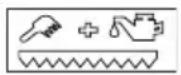
Cleaning and maintenance of the scythe attachment.
SAFETY INSTRUCTIONS
The equipment should be used only if in good order and condition
■ Young people under 16 years of age, and people who do not know the instructions for use, are not allowed to use the machine.
- Observe local regulations regarding minimum age requirements for operating the machine.
■ Wear long trousers and sturdy shoes.
■ Remove foreign objects from the working area.
- Check the ground on which the mower is going to be used. Remove all objects that could be picked up and thrown out.
■ Never mow when there is anyone, especially children or animals, in the vicinity.
- Observe local ordinances regarding operating times.
■ Only mow during daylight hours or with good artificial lighting.

CAUTION!
Always perform a visual check prior to start-up.
■ Only replace damaged or worn parts by genuine spare parts.
The user is responsible for accidents involving other people and their property.
- Do not deactivate safety and protection devices
■ When starting the engine
No-one is allowed to be in front of the scythe attachment
The blade and wheel drive must be switched off
■ Only use the mower on grassy areas.
It is essential to put the guard bar on the scythe attachment for transporting or lifting the mower.
- Switch off the blade drive when moving outside the mowing area.
Do not place your hands and feet close to any rotating parts.
■ Only control the machine using the handlebar. This ensures the necessary safety clearance.
■ Always ensure stability when working. - Keep exhaust and engine clean.

CAUTION!
Danger of fire!
Remove flammable objects from the exhaust and the cylinder area.
If working on slopes:
- Never work on a smooth and slippery slope.
■ Always make sure you are positioned securely.
■ Always work across the slope, never upward or downward.
Do not work on slopes with a more than 10^ gradient!
Take particular care when turning!
- Do not leave the appliance unsupervised.
Before leaving the equipment unattended:
■ Turn the engine off
- Wait for the cutting unit to stop
■ Remove the spark plug connector
- Do not change the engine governor settings.
SAFETY INSTRUCTIONS FOR THE SCYTHE ATTACHMENT
Some of the blades on the scythe attachment are exposed. These represent a significant risk of injury in case of lack of care during handling.
Always put on the guard bar for the scythe attachment under the following circumstances:
- Installing the scythe attachment on the mower
Cleaning the machine
■ Transport and storage of the mower
Assembly work on the scythe attachment
Renewing damaged guard bars
Fire danger! Petrol is highly flammable!
■ Store petrol in designated containers only.
■ Only refuel in open air.
■ Never smoke while refilling!
Use a funnel or a filler pipe when refuelling so that no fuel is spilled on the engine, the deck or the ground.
Do not open the tank cap while the engine is running or if the machine is hot.
- Replace a damaged petrol tank and/or tank cap.
■ Renew exhaust silencers if damaged.
If petrol has been spilt:
Do not start the engine
Do not start the equipment
Clean the equipment.

CAUTION!
Danger of burns!
Running engines generate heat. Parts of the engine, especially the exhaust, get extremely hot.

WARNING!
Never leave an engine running in an enclosed space. Toxic hazard!
ASSEMBLY

CAUTION!
The machine must not be put in operation before it has been assembled completely.
Assemble this mower in accordance with the separately enclosed assembly manual.
STARTUP
Initial commissioning

Numbers in italics, e.g. (2-1), refer to the figures.

WARNING!
Petrol engine: Fill with oil and petrol before taking into operation for the first time!
Travel transmission
The gear oil is a factory fill.
■ Always observe the operating instructions supplied by the engine manufacturer.
Setting the handlebar height
Setting the handlebar height
The height is usually adjusted to hip level.
- Loosen the screws on the housing console.
- Set the height of the handlebars using the longitudinal holes.
- Retighten the screws.
Depending on the model, the handlebar can additionally be adjusted using the upper or lower height settings on the housing console.
Setting the cutting height
The cutting height is adjusted using the skids.
Standard cutter bar
steplessly adjustable cutting height up to approx. 6 cm
Loosen nuts.
■ Move the skids to the required height.
Retighten the nuts.

CAUTION!
Both skids must be set to the same height!
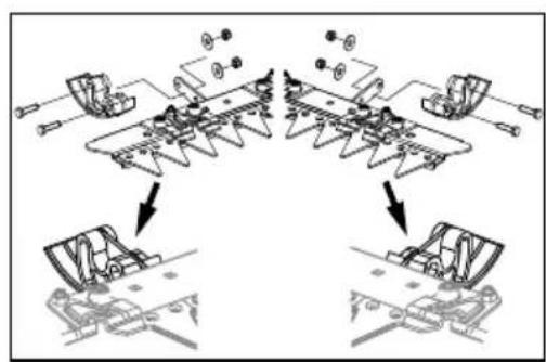
ESM cutter bar
Mounting the skid holders as skids
The cutter bar cuts close to the ground.
The cutter bar cuts close to the ground, the curved side points downwards.
Mounting adjustable skids
steplessly adjustable cutting height up to approx. 6 cm.
Mount the adjustable skid holders as shown in the illustration, the curved side points upwards.
Mount the skids as shown in the illustration.
Setting the cutting height
■ Loosen the nuts (2 nuts per skid).
■ Move the skids to the required height.
Retighten the nuts.

CAUTION!
Both skids must be set to the same height!
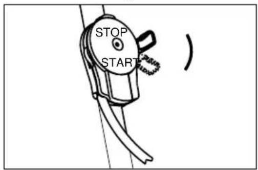
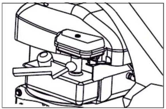
Starting the engine

CAUTION!
The clutch levers for the wheel and cutter drives must not be engaged when starting the engine!
Set the throttle lever to the << START>> position. Press the primer button 3x with intervals of approx. 2 seconds.
If the temperature is below 10^ C, press the primer button 5x.

Do not press primer buttons when engine is warm.
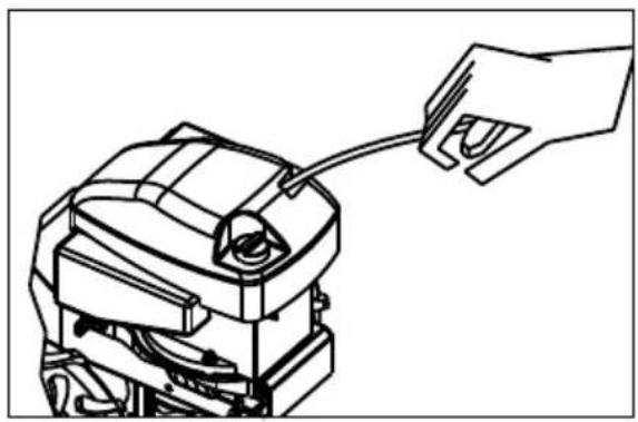
Quickly pull out the starter cable and then allow it to slowly rewind.
As soon as the engine is running, set the throttle lever between the "start" and "stop" positions according to the desired engine speed.
To start mowing, move the lever to the

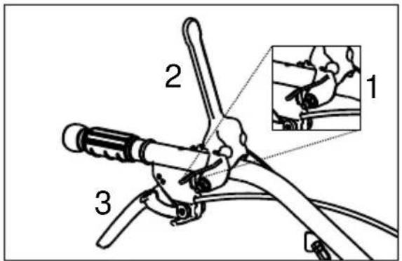
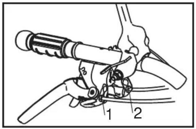
Switching on scythe attachment (11)
Swivel operator presence control (11-1) away.
Push clutch lever (11-2) fully down and hold it there.

DANGER!
The mowing mechanism is not allowed to start moving until the lever has moved through half of its travel, adjust the Bowden cable if necessary – (see: Adjusting Bowden cables).
Switching on travel drive (11)
Pull clutch lever (11-3) against the handlebar and hold it there.

DANGER!
The travel drive is not allowed to start moving until the lever has moved through half of its travel, adjust the Bowden cables if necessary – (see: Adjusting Bowden cables).
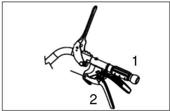
Version with forward and reverse gears (12)
Clutch lever (12-1) = travel drive forwards
Clutch lever (12-2) = travel drive backwards

WARNING!
Do not pull both clutch levers at the same time!
Travel drive forwards
or
Travel drive backwards
Not both
Switching off travel drive (12)
Release clutch lever (12-1) or (12-2).
Switching off scythe attachment (11)
Release clutch lever (11-2).
Switching off engine (13)
Move throttle lever to the << STOP >> position.
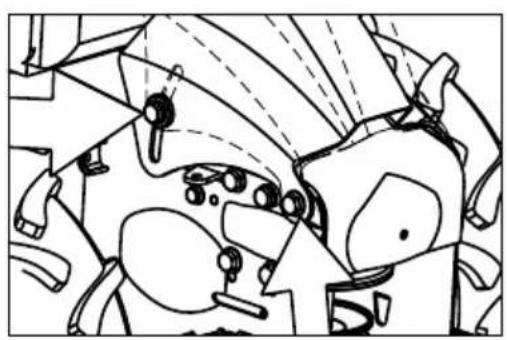
SCYTHE ATTACHMENT
Clean the scythe attachment after each use, especially the guidance and sliding surfaces. Remove the mowing blade to do this.
Then oil all moving parts.
Only use biodegradable lubricants!
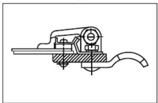
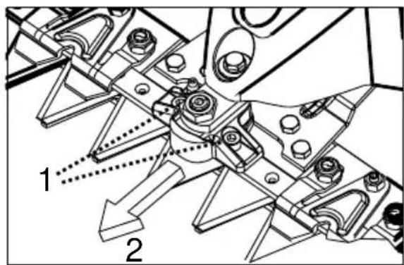
Removing mowing blade on the scythe attachment
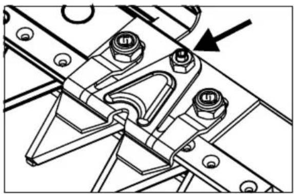
Standard scythe attachment (14, 15)
-
Unscrew screws (14-1).
-
Remove part (14-2) forwards.
-
Note the installation direction when reinstalling the part – projection in travel direction!
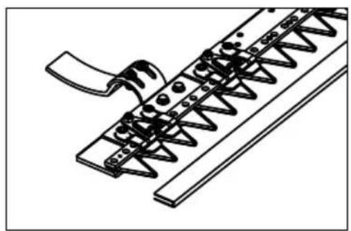
-
Loosen guides for mowing blade (15).
-
Unscrew hex nuts and unscrew threaded pins a little.
-
Pull out mowing blade to the side..
Re-install in the reverse sequence.
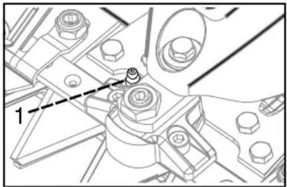
Setting the cutting play (15)
- Screw in the threaded pins by hand until you can feel resistance – then continue 12 a turn further.
- Secure the threaded pins with a locknut.
- It must still be possible to move the mowing blade freely by hand after the setting procedure.
- Make a trial cut - screw the threaded pins slightly further in if the cutting performance is insufficient.
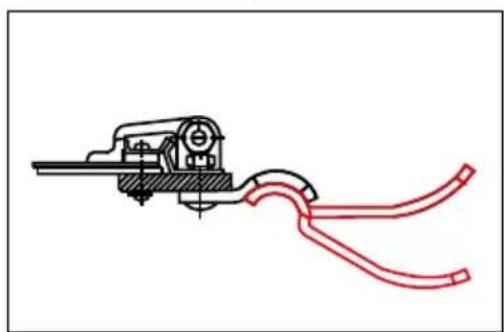
ESM scythe attachment (14)
- Unscrew screws (14-1).
- Remove part (14-2) forwards.
- Note the installation direction when reinstalling the part 2 – projection in travel direction!
For further information about removal of the mowing blade as well as maintenance of the scythe attachment, see the accompanying document: ESM scythe attachment Universal SC

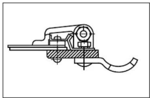
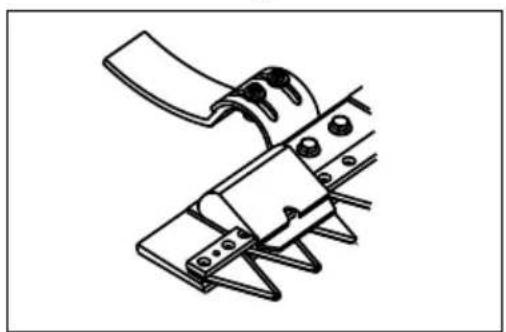
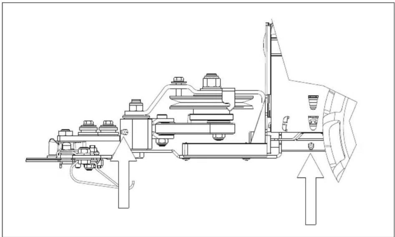
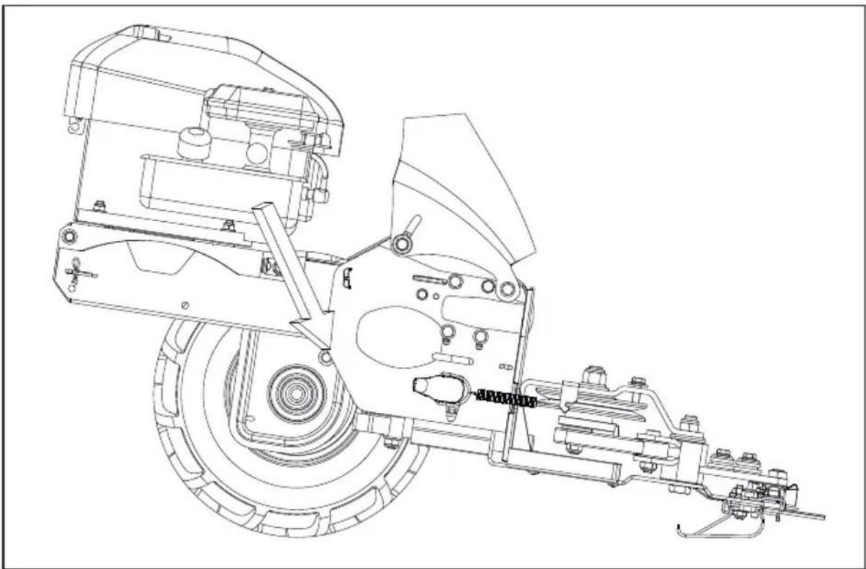
3 grease nipples
(16-1, 17)
Grease driver (16) and drive for scythe attachment (17) every 8 working hours with commercially available multipurpose grease.
Regrinding and renewing blades
Regrind blunt blades using a suitable whetstone, maintaining the cutting angle (approx. 35 – 40°) – remove the mowing blade to do this.
Renew worn or damaged blades – customer service workshop.
■ Have a professional check:
■ after bumping against an obstacle
■ if the engine stops suddenly
■ if the cutter bar is bent
■ if the gears are damaged
■ if the belt is damaged.
TRAVEL TRANSMISSION
(18)
Regularly check the oil level in the transmission
- Position the machine horizontally.
- Unscrew and remove the oil filler cap.
- Oil level: Up to the bottom edge of the fill opening. Top up gear oil if necessary.
Oil grade Gear oil SAE 80
| Oil fill volume for machines with | |
| Forwards gear only approx. 0.25 l | |
| Forwards and reverse gear | approx. 0.50 l |
ENGINE
Oil change, air filter, spark plug
See the operating manual supplied by the engine manufacturer.
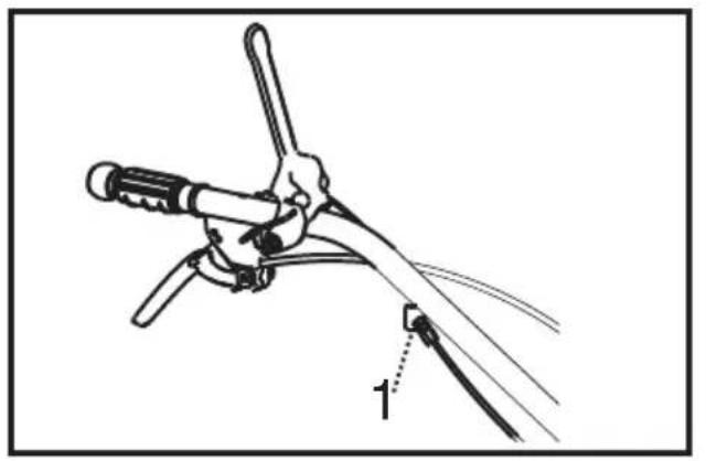
Adjustment of the Bowden cables
Cutter bar (without a lock nut)
Wheel drive
- loosen the lock nut
- use the adjusting screw to readjust
Correct setting:
The cutters and the wheel drive should only start to move after the lever has travelled half the distance.
- Retighten the lock nuts.
MAINTENANCE AND CARE
- Never lift or carry the machine when the engine is running. Switch off the engine, pull out the spark plug connector, wait for all moving parts to come to a stop.

CAUTION!
Fire hazard!
Do not store fuelled machine in buildings where the petrol fumes might come into contact with naked flames or sparks!
■ Only drain the petrol tank outdoors.
- Do not spray the machine with water! Penetrating water (ignition system, carburettor...) can lead to malfunctions.

If the mower is tilted to the side, the requirements vary depending on the engine manufacturer:
BRIGGS &
STRATTON
The spark plug
must point upwards!
See the instructions for use from the engine manufacturer!
■ Always wear protective gloves when working on the cutting tool.
- Let the engine cool down before storing in enclosed rooms
Spare parts and accessories
■ Only use genuine spare parts and genuine accessories.
■ Subject to changes in design and configuration.
DISPOSAL
Do not dispose of worn-out machines or spent batteries (including rechargeable batteries) in domestic waste!
The packaging, machine and accessories are made from recyclable materials and must be disposed of accordingly.
TROUBLESHOOTING

CAUTION!
Risk of injury!
Remove the spark plug connector before any maintenance or cleaning jobs!
Problem Solution
| Engine does not start | ■ If the engine is cold: press the primer ■ Top up fuel ■ Move the throttle lever to the start position ■ Push the spark plug connector onto the spark plug ■ Check spark plug, renew if necessary ■ Clean air filter |
| Engine output drops off | ■ Call customer service workshop, Resharpen / replace the blades ■ Clean air filter |
| Inexact cut Call customer service workshop ■ Resharpen / replace the blades ■ Readjust the cutting play | |
Problem Solution
Cutter drive / wheel drive not functioning
- Readjust Bowden cable
- Call customer service workshop, V - belt defect

Please contact customer service in case of faults which are not mentioned in this table or which you cannot repair alone.
WARRANTY
We will address claims for any defects in materials and workmanship during the statutory period of limitation by means of repairs or replacements of our choice. The period of limitation is governed by the laws of the country in which the machine was purchased.
Our warranty applies only if:
The machine has been properly handled
The operating instructions have been adhered to
■ Original replacement parts have been used
The warranty is no longer in effect if:
■ Efforts have been made to repair the machine
■ Technical modifications have been made to the machine
The machine has not been used for its intended purpose
The warranty does not cover:
■ Damage to paint work through normal use
Parts subject to wear as indicated in the replacement parts list with a box [xxx xxx (x)]
Internal combustion engines – separate warranty conditions of the respective engine manufacturer apply
The warranty period begins with the purchase by the first buyer. The warranty period begins on the date that appears on the original purchase receipt. In the event of a warranty claim, please your contact supplier or the nearest authorised customer service centre with this warranty declaration and the purchase receipt in hand. This warranty does not affect the legal warranty claims by the purchaser against the seller.
VERTALING VAN DE ORIGINELE GEBRUIKERSHANDLEIDING
Inhoudsopgave
Fare for forbrenning!
Motorer som går produserer varme. Motordeler, særlig eksosrøret, blir ekstremt varme.

