AquaThermica Eco 260 S - Boiler Tesy - Free user manual and instructions
Find the device manual for free AquaThermica Eco 260 S Tesy in PDF.

| Product type | Heat pump water heater for domestic hot water |
| Brand | Tesy |
| Model | AquaThermica Eco 260 S |
| Tank capacity | 260 liters |
| Power supply | 230 V ~ 50 Hz, single phase |
| Maximum water temperature | 70 °C (legionella disinfection cycle) |
| Adjustable water temperature range | Up to 65 °C in heat pump mode, beyond with electric backup |
| Operating modes | Heat pump, electric heating, quick mode, standby mode |
| Special functions | On/off timer, anti-freeze, defrost, circulation pump anti-block, continuous ventilation |
| Display | LED screen with set temperature, actual temperature, clock, error codes |
| Anti-freeze protection | Trigger at 5 °C, stop at 10 °C |
| Overheating protection | Overheat switch (code E3) |
| High/low pressure protection | High (E1) and low pressure (E2) pressostats |
| Control panel lock | Long press 5 s on △ and ▽ keys |
| Maintenance and cleaning | Reserved for qualified professional; do not use without water |
| Environmental standards | Complies with RoHS (2011/65/EU) and WEEE (2012/19/EU) directives |
| Languages of the manual | French, English, German, Spanish, Italian, Dutch, Polish, Portuguese, Romanian, Bulgarian, Greek, etc. |
Frequently Asked Questions - AquaThermica Eco 260 S Tesy
User questions about AquaThermica Eco 260 S Tesy
0 question about this device. Answer the ones you know or ask your own.
Ask a new question about this device
Download the instructions for your Boiler in PDF format for free! Find your manual AquaThermica Eco 260 S - Tesy and take your electronic device back in hand. On this page are published all the documents necessary for the use of your device. AquaThermica Eco 260 S by Tesy.
USER MANUAL AquaThermica Eco 260 S Tesy
For Domestic Hot Water Heat Pump
EN
ES
DE
IT
FR
PL
NL
PT
GR
BG
HR
SL
SRB
RO
DOMESTIC HOT WATER HEAT PUMP
BOMBA DE CALOR PARA AGUA CALIENTE SANITARIA
WARMWASSER – WÄRMEPUMPE
POMPA DI CALORE PER ACQUA CALDA SANITARIA
POMPE À CHALEUR EAU CHAUDE SANITAIRE
POMPY CIEPŁA DO CIEPŁEJ WODY
WARMTEPOMP VOOR SANITAIR WARM WATER
BOMBA DE CALOR PARA ÁGUA QUENTE SANITÁRIA
HPWH 3.1 200/260 U02 S
natural_image
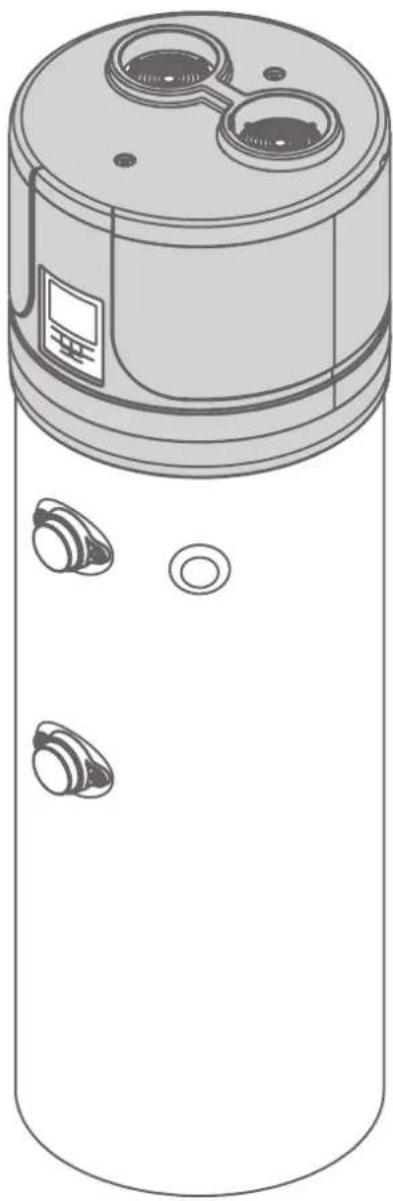
Technical line drawing of a cylindrical device with multiple circular ports and a central top (no text or symbols)Dear Customer,
Thank you for choosing this product!
TESY, has always paid a great deal of attention to environmental problems, therefore, we have used technologies and materials with a low environmental impact to manufacture products in conformity with RAEE – ROHS (2002/95/CE and 2003/108/CE) community standards.
IMPORTANT RULES AND SAFETY INSTRUCTIONS
IMPORTANT! Non observance of below described rules leads to warranty fault and the producer bear no more responsibilities for your appliance!
- This appliance is not intended for use by persons (including children) with reduced physical, sensory or mental capabilities, or lack of experience and knowledge, unless they have been given supervision or instruction concerning use of the appliance by a person responsible for their safety.
- Children should be supervised to ensure that they do not play with the appliance.
- Children must not play with the equipment. Cleaning and maintenance intended to be carried out by the user must not be performed by unsupervised children.
- The use of the appliance for any purpose other than that it is intended is prohibited
- Do not use the storage tank if it is not filled with water.
• Installation, commissioning and maintenance of the device must be performed by qualified and authorized personnel. Do not attempt to install the device yourself. - The appliance must only be installed in premises with normal fire resistance.
- Usage of this device at temperature and pressure level above prescribed leads to warranty violation!
- This device is intended for heating of potable water in liquid state. using different fluids in different states leads to warranty violation!
- Device's heat exchangers are intended for use with circulating clean water and mixture of it and Propylene GLYCOL at liquid state. The presence of anticorrosion additives is obligatory. Using different fluids in different states leads to warranty violation!

- Read carefully the “Installation and maintenance manual”, that is an integral part of
your appliance!
- Check if the unit is installed and connected according to the “Installation and maintenance manual”, that is an integral part of your appliance!
- Check if the tank is full with water!
- Check if the electric main supply is present an it is with accordance to the local regulations!
- Check that the air ducts or air inlet/outlet are not blocked!
OPERATING MODES. USER INTERFACE
flowchart
graph TD
    A["Hand Clicking Button"] --> B["Turn ON"]
    B --> C["Hand Clicking Button"]
    C --> D["Standby"]

flowchart
graph TD
    A["Adjust Hour/Minute"] --> B["Set Hour/Minute"]
    B --> C["Confirm"]
    D["Timer"] --> E["Set Hour"]
    E --> F["Confirm Hour"]
    F --> G["Set Minute"]
    G --> H["Confirm Minute"]
    H --> I["Save & Exit Cancel"]
    I --> J["Timer"]


flowchart
graph TD
    A["Check Parameters A-H"] --> B["Arrow to Triangle"]
    C["Check Parameters 1-35"] --> D["Arrow to Triangle"]
    B --> E["Arrow to Triangle"]
    D --> F["Arrow to Triangle"]
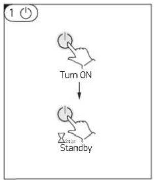
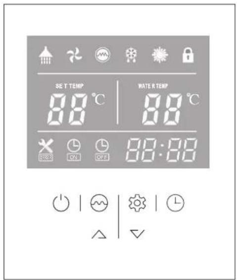
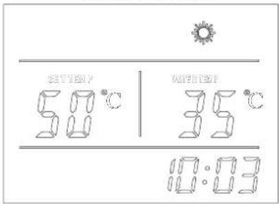
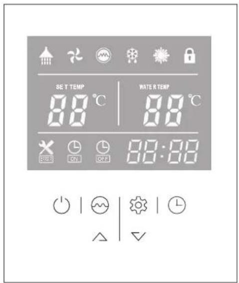
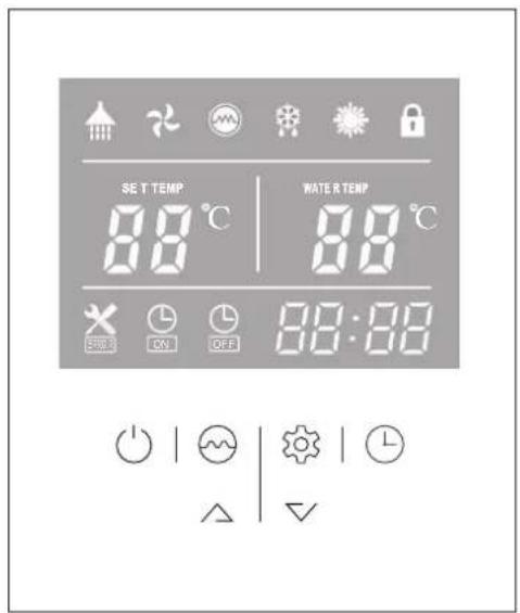
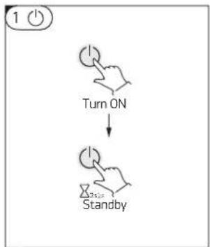
When connecting the appliance to the main power supply, all icons are displayed on the controller screen for 3 seconds. After that an initial check is undergoing. If everything is ok, the unit enters into a standby mode (fig.01) Press and hold the 'button' for 2 seconds when the unit is in standby. The "Heating mode" will start. The display will look like (fig02)
To switch the unit OFF press button and hold it for 2 seconds while the unit is running.
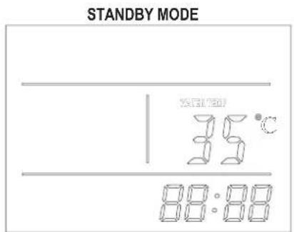
Fig. 01 Fig. 02
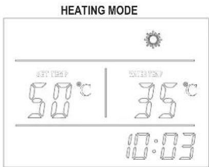
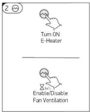
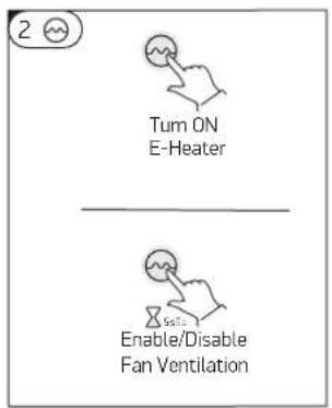
2 While the heat pump is running, press this button to turn 'ON' "Boost mode". The heater icon will be shown, and the electrical heater will work according to the control program together with the compressor until the set temperature is reached.
When the heat pump is ON, press this button ⬇ and hold for 5 seconds to enable or disable the fan ventilation function. If this function is enabled the fan will continue working to ventilate the air, even when the water temperature reaches the set point and the unit is in standby mode. On the contrary If this function is disabled the fan will stop, when the water temperature reaches the set point and the unit is in standby mode.
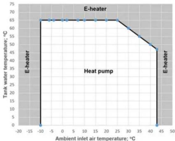
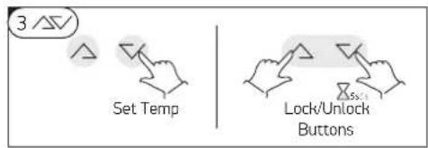
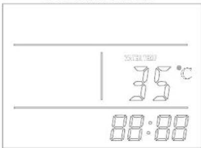
3/57 During running status, press or button to adjust the set temperature of water tank directly. The maximum achievable water temperature by heat pump only, depends on outside air inlet temperature and could be seen on picture:
Press /and buttons at the same time and hold for 5 seconds, the buttons are locked. Press /and buttons at the same time and hold for 5 seconds again, the buttons are unlocked
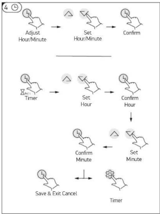
-After switching the appliance on, press button to entry the clock setting interface, hour and minute icons "88:88" flash together;>Press button to switch hour/minute setting, press the △and ▼buttons to set the exact hour(s) and minute(s);>Press button again to confirm and exit.
After switching the appliance on, press and hold ⏻ button for 5 seconds to enter the timer setting interface, the timer on icon and hour icon "88:" will flash together;>- Press the △ and ▼ buttons to set the exact hour(s).>- Press ⏻ button to transfer to minute setting, minute icon ":88" will flash, press the △ and ▼ buttons to set the exact minute(s).>- Press button ⏻ again to save and exit the timer setting interface.
Press button to cancel the timer, while the "timer settings" mode is active
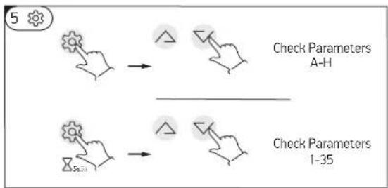
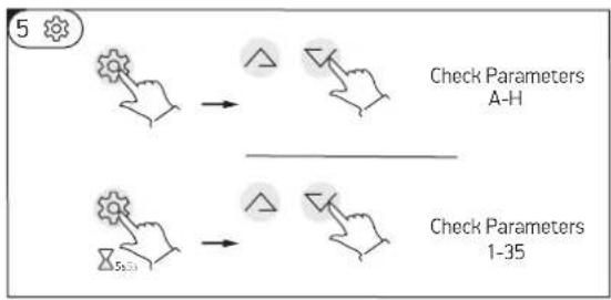
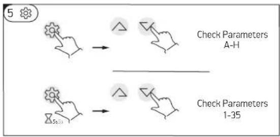
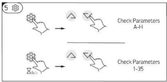
5 Press this button to enter temp and EXV open step checking.
-Press the /and buttons to check the temp sensor values and EXV open steps (parameters A-F).
-In any status, press this button and hold for 5 seconds, entry the system parameter checking interface.
-Press the /and buttons to check the system parameters.
NOTE:
1) The timer 'ON' and timer 'OFF' functions can be set at the same time.
2) The timer settings are repeating.
3) The timer settings are still valid after a sudden power cut.
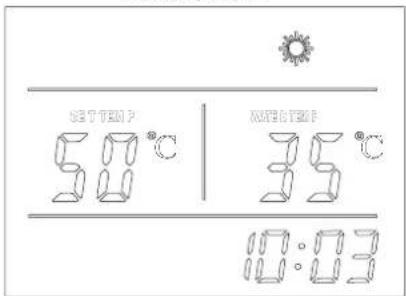
HEATING MODE
When connecting the appliance to the main power supply, all icons are displayed on the controller screen for 3 seconds. After that an initial check is undergoing. If everything is ok, the unit enters into a standby mode
HEATING MODE

line
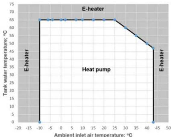
| Ambient inlet air temperature; °C | Tank water temperature; °C | | --------------------------------- | --------------------------- | | -10 | 65 | | 25 | 65 | | 45 | 45 |Fig. 04 Fig. 03
The heat pump will start working continuously in order to reach the set temperature. If the set temperature is adjusted to above 65oC, E-Heater will start working to continue heating the water to the set temperature.
If the outside air temperature is less than -10oC or above 44oC, theE-Heater will work only!
While the heat pump is working at a low outside air temperature, defrosting mode could be activated automatically in order to melt the ice collected on the evaporator. This is a normal situation.
The maximum achievable water temperature by heat pump only, depends on outside air inlet temperature and could be seen on picture (fig. 04)
If the set temperature (via control display) is more than achievable one as per picture, the E-heater will be switch ON automatically to reach it.

In order to save energy, avoid setting the temperature above 55oC if not necessary! This way the heat pump will work without the help of the E-Heater!
"E heater only"
If the E-heater button ☺ on the control panel has been turned on manually when the unit is instandby mode, the E-heater will work only, until the temperature of the upper tank (5) reaches the set temperature TS2;
URGENT NEED OF HOT WATER!
While the heat pump is running, press this button ☺ to turn 'ON' "Boost mode". The heater icon ☺ will be shown, and the electrical heater will work according to the control program together with the compressor until the set temperature is reached.
WITH CARE FOR YOUR HEALTH!
The E-heater will start each week at the setting time automatically, regardless if the machine is on or in standby mode. E-heater will stop working, when the tank temperature reaches 70oC (disinfection against legionella bacteria)
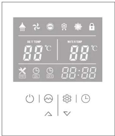
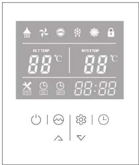
MEANING OF LED ICONS!

| 1 Hot water available | The icon indicates that the domestic hot water temperature reaches the set point. The hot water is available for use. Heat pump is standby |
| 2 Fan ventilation The icon indicates that the fan ventilation function is enabled. | |
| 3 Electrical heating | The icon indicates that the electrical heating function is enabled. The electrical heater will work according to the control program. |
| 4 Defrosting | The icon indicates that the defrosting function is enabled. This is an automatic function, the system will enter or exit the defrosting according to the inner control program |
| 5 Heating The icon indicates that the current operation mode is Heating. | |
| 6 Key lock | The icon indicates the key lock function is enabled. The keys cannot be operated until this function is disabled |
| 7 Left temperature display | The display shows the set water temperature.In case any malfunction occurs, this section will display the related error code. |
| 8 Right temperature display | When checking or adjusting the parameters, this section will display the related parameter value |
| 9 Time display The display shows the clock time or timer time. | |
| 10 Timer ‘ON’ The icon indicates that the timer ‘ON’ function is enabled. | |
| 11 Timer ‘OFF’ The icon indicates that the timer ‘OFF’ function is enabled. | |
| 12 Error The icon indicates there is malfunction. | |
IF SOMETHING LOOKS & SOUNDS STRANGE!
Antifreeze mode
When the unit is in standby mode, if the water temperature in the tank is below 5^ C (tank water frozen protection), only the E-heater will work, until tank temperature increases above 10^ C or the unit is turned on.
Defrosting
The icon 88 indicates that the defrosting function is enabled. This is an automatic function, the system will enter or exit the defrosting function according to the inner control program.
Pump anti-block function
When the external pump (if any) stops for 12 hours, it will be forced to run for 2 minutes.
Fan ventilation
The icon ⚙ indicates that the fan ventilation function is enabled. When the heat pump is ON, press this button ⚙ and hold for 5 seconds to enable or disable the fan ventilation function. If this function is enabled the fan will continue working to ventilate the air, even when the water temperature reaches the set point and the unit is in standby mode. On the contrary If this function is disabled the fan will stop, when the water temperature reaches the set point and the unit is in standby mode.
IF SOMETHING GOES WRONG!

- Switch off the unit! Disconnect it the from main power supply!
- Call to the service and inform them about the error code or describe all abnormalities and strange behavior or noise of your appliance!
Error codes
During standby or running status, if there is a malfunction, the unit will stop automatically and show the error code on the left screen of the controller. See the installation and maintenance manual
ERROR CODE
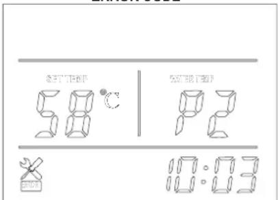
Fig. 05
| Error Code LED indicator | ||
| Stand by Dark | ||
| Normal running Bright | ||
| Lower tank water temp sensor failure P1 | ★●(1 flash 1 dark) | |
| Upper tank water temp sensor failure P2 | ★★●(2 flash 1 dark) | |
| Coil temp sensor failure P3 | ★★★●(3 flash 1 dark) | |
| Air return temp sensor failure P4 | ★★★★●(4 flash 1 dark) | |
| Ambient temp sensor failure P5 | ★★★★★●(5 flash 1 dark) | |
| High pressure protection E1 | ★★★★★★●(6 flash 1 dark) | |
| Low pressure protection E2 | ★★★★★★★●(7 flash 1 dark) | |
| Over heat protection E3 | ★★★★★★★★★●(8 flash 1 dark) | |
| Defrosting | ★★★★★★★★......(long flash) | |
| Communication failure E8 Bright | ||
This symbol on the product(s) and / or accompanying documents means that used electrical and electronic equipment (WEEE) should not be mixed with general household waste. For proper treatment, recovery and recycling, please take this product(s) to designated collection points where it will be accepted free of charge. Disposing of this product correctly will help save valuable resources and prevent any potential negative effects on human health and the environment, which could otherwise arise from inappropriate waste handling.
Estimados clientes
flowchart
graph TD
    A["Hand Clicking Button"] --> B["Turn ON"]
    B --> C["Hand Clicking Button with Note"]
    C --> D["Standby"]


flowchart
graph TD
    A["Adjust Hour/Minute"] --> B["Set Hour/Minute"]
    B --> C["Confirm"]
    D["Timer"] --> E["Set Hour"]
    E --> F["Confirm Hour"]
    F --> G["Set Minute"]
    G --> H["Confirm Minute"]
    H --> I["Save & Exit Cancel"]
    I --> J["Timer"]


flowchart
graph TD
    A["Step 1: Hand Click"] --> B["Check Parameters A-H"]
    C["Step 2: Hand Click"] --> D["Check Parameters 1-35"]

flowchart
graph TD
    A["Adjust Hour/Minute"] --> B["Set Hour/Minute"]
    B --> C["Confirm"]
    D["Timer"] --> E["Set Hour"]
    E --> F["Confirm Hour"]
    F --> G["Set Minute"]
    G --> H["Confirm Minute"]
    H --> I["Save & Exit Cancel"]
    I --> J["Timer"]


flowchart
graph TD
    A["Check Parameters A-H"] --> B["Arrow to Triangle"]
    C["Check Parameters 1-35"] --> D["Arrow to Triangle"]
    B --> E["Arrow to Triangle"]
    D --> F["Arrow to Triangle"]
line
| Ambient inlet air temperature; °C | Tank water temperature; °C | | --------------------------------- | -------------------------- | | -10 | 65 | | 25 | 65 | | 45 | 45 |Fig. 04 Fig. 03

flowchart
graph TD
    A["Adjust Hour/Minute"] --> B["Set Hour/Minute"]
    B --> C["Confirm"]
    D["Timer"] --> E["Set Hour"]
    E --> F["Confirm Hour"]
    F --> G["Set Minute"]
    G --> H["Confirm Minute"]
    H --> I["Save & Exit Cancel"]
    I --> J["Timer"]


flowchart
graph TD
    A["Check Parameters A-H"] --> B["Arrow to Triangle"]
    C["Check Parameters 1-35"] --> D["Arrow to Triangle"]
    B --> E["Arrow to Triangle"]
    D --> F["Arrow to Triangle"]
When connecting the appliance to the main power supply, all icons are displayed on the controller screen for 3 seconds. After that an initial check is undergoing. If everything is ok, the unit enters into a standby mode (fig.01) Press and hold the 'button' for 2 seconds when the unit is in standby. The "Heating mode" will start. The display will look like (fig02)
Fig. 05
flowchart
graph TD
    A["Adjust Hour/Minute"] --> B["Set Hour/Minute"]
    B --> C["Confirm"]
    D["Timer"] --> E["Set Hour"]
    E --> F["Confirm Hour"]
    F --> G["Set Minute"]
    G --> H["Confirm Minute"]
    H --> I["Save & Exit Cancel"]
    I --> J["Timer"]


flowchart
graph TD
    A["Check Parameters A-H"] --> B["Arrow to Triangle"]
    C["Check Parameters 1-35"] --> D["Arrow to Triangle"]
    B --> E["Arrow to Triangle"]
    D --> F["Arrow to Triangle"]

flowchart
graph TD
    A["Adjust Hour/Minute"] --> B["Set Hour/Minute"]
    B --> C["Confirm"]
    D["Timer"] --> E["Set Hour"]
    E --> F["Confirm Hour"]
    F --> G["Set Minute"]
    G --> H["Confirm Minute"]
    H --> I["Save & Exit Cancel"]
    I --> J["Timer"]


flowchart
graph TD
    A["Hand with gear icon"] --> B["Check Parameters A-H"]
    C["Hand with gear icon"] --> D["Check Parameters 1-35"]
When connecting the appliance to the main power supply, all icons are displayed on the controller screen for 3 seconds. After that an initial check is undergoing. If everything is ok, the unit enters into a standby mode
TRYB OGRZEWANIA

line
| Ambient inlet air temperature (°C) | Tank water temperature (°C) | | ---------------------------------- | --------------------------- | | -10 | 65 | | 25 | 65 | | 45 | 45 |Fig. 04 Fig. 03
WARMTEPOMP VOOR SANITAIR WARM WATER
Beste klant,

flowchart
graph TD
    A["Adjust Hour/Minute"] --> B["Set Hour/Minute"]
    B --> C["Confirm"]
    D["Timer"] --> E["Set Hour"]
    E --> F["Confirm Hour"]
    F --> G["Set Minute"]
    G --> H["Confirm Minute"]
    H --> I["Save & Exit Cancel"]
    I --> J["Timer"]


flowchart
graph TD
    A["Hand with gear icon"] --> B["Check Parameters A-H"]
    C["Hand with gear icon"] --> D["Check Parameters 1-35"]
The E-heater will start each week at the setting time automatically, regardless if the machine is on or in standby mode. E-heater will stop working, when the tank temperature reaches 70oC (disinfection against legionella bacteria)
BESCHRIJVING VAN DE LED-PICTOGRAMMEN

Fig. 05
flowchart
graph TD
    A["Hand Clicking"] --> B["Turn ON"]
    B --> C["Hand Clicking with Flask"]

flowchart
graph TD
    A["Adjust Hour/Minute"] --> B["Set Hour/Minute"]
    B --> C["Confirm"]
    D["Timer"] --> E["Set Hour"]
    E --> F["Confirm Hour"]
    F --> G["Set Minute"]
    G --> H["Confirm Minute"]
    H --> I["Save & Exit Cancel"]
    I --> J["Timer"]


flowchart
graph TD
    A["Check Parameters A-H"] --> B["Arrow to Triangle"]
    C["Check Parameters 1-35"] --> D["Arrow to Triangle"]
    B --> E["Arrow to Triangle"]
    D --> F["Arrow to Triangle"]
line
| Ambient inlet air temperature; °C | Tank water temperature; °C | | --------------------------------- | -------------------------- | | -10 | 65 | | 25 | 65 | | 45 | 45 |MEANING OF LED ICONS!
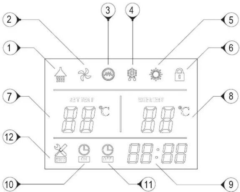
Fig. 05

flowchart
graph TD
    A["Check Parameters A-H"] --> B["Arrow to Triangle"]
    C["Check Parameters 1-35"] --> D["Arrow to Triangle"]
    B --> E["Arrow to Triangle"]
    D --> F["Arrow to Triangle"]

flowchart
graph TD
    A["Adjust Hour/Minute"] --> B["Set Hour/Minute"]
    B --> C["Confirm"]
    D["Timer"] --> E["Set Hour"]
    E --> F["Confirm Hour"]
    F --> G["Set Minute"]
    G --> H["Confirm Minute"]
    H --> I["Save & Exit Cancel"]
    I --> J["Timer"]


flowchart
graph TD
    A["Hand with gear icon"] --> B["Check Parameters A-H"]
    C["Hand with gear icon"] --> D["Check Parameters 1-35"]
Fig. 05
VAŽNA SIGURNOSNA PRAVILA I UPUTE
flowchart
graph TD
    A["Hand Clicking Button"] --> B["Turn ON"]
    B --> C["Hand Clicking Button with Note"]
    C --> D["Standby"]

flowchart
graph TD
    A["Adjust Hour/Minute"] --> B["Set Hour/Minute"]
    B --> C["Confirm"]
    D["Timer"] --> E["Set Hour"]
    E --> F["Confirm Hour"]
    F --> G["Set Minute"]
    G --> H["Confirm Minute"]
    H --> I["Save & Exit Cancel"]
    I --> J["Timer"]

flowchart
graph TD
    A["Check Parameters A-H"] --> B["Arrow to Triangle"]
    C["Check Parameters 1-35"] --> D["Arrow to Triangle"]
    B --> E["Arrow to Triangle"]
    D --> F["Arrow to Triangle"]
1 Kpad spojite uređaj na strujno napajanje, sve ikoni se prikazuju na zaslonu u trajanju od 3 sekunde. Nakon automatske provjere, uređaj ulazi u stanje pripravnosti:(fig.01)
NAČIN GRIJANJA

Fig. 01 Fig. 02
Dok radi toplinska pumpa, pritisnite tipku za aktiviranje načina rada "Brzo zagrijavanje". Na zaslonu će se pojaviti ikona i električni grijač počet će raditi prema zadanom programu istodobno s kompresorom, sve dok se ne postigne željena temperatura.
Kad je uređaj uključen, pritisnite i držite tipku 5 sekundi da biste aktiirali ili deaktivirali funkciju „ventilator“. Ako je funkcija aktivirana, ventilator će nastaviti raditi čak i kada temperatura vode dosegne navedenu točku i uređaj je u stanju pripravnosti. Inače - ako je ova funkcija isključena, ventilator prestaje raditi kada temperatura vode dosegne zadanu vrijednost, a uređaj je u stanju pripravnosti.
3Dok radi toplinska pumpa, pritisnite tipku ili i za podešavanje željene temperature vode.
Maksimalna dostižna temperatura vode samo kroz agregat toplinske pumpe, izravno ovisi o temperaturi ulaznog zraka. Pogledajte tablicu ispod:
- Pritisnite tipke /li istovremeno i držite 5 sekundi, da bi zaključali upravljačku ploču.
- Istovremeno pritisnite tipke △ ili ▽ i zadržite 5 sekundi za ponovno otključavanje upravljačke ploče.
4 - Kad je uređaj uključen, za ulazak u postavke sata pritisnite tipku Ikone sata i minuta „88:88“ trepte istovremeno;
Da biste aktivirali postavke sata i minuta, pritisnite tipku ⏻ za podešavanje sata i minuta koristite tipke △ i ▽.
Da biste potvrdili izlaz iz postavke sata ponovno pritisnite tipku
- Nakon uključivanja uređaja, pritisnite i držite tipku ⏻ 5 sekundi za ulazak u postavke sata timera, ikone timera i sata "88:" će treptati istovremeno;
Koristite tipke △ i ▽ za podešavanje sata;>- Pritisnite tipku ⏻ da bi otovrili postavku za minute, ikona minuta ":88" će trepne, a pomoću tipki ▲ podesite minute.
Pritisnite tipku Ⓐ za ulazak u postavke isključivanja timera; ikona isključivanja timera i ikona za sate „88:“ će
istovremeno treptati.> - Koristite tipke△ i ▼ za podešavanje sata;> - Pritisnite tipku 📊 za ulazak u postavke minuta timera, ikona minute će treptatii, koristite tipke △ i ▼ za podešavanje minute ; >- Ponovno pritisnite tipku 📊 za spremanje i izlazak iz podešenja timera.> - Pritisnite tipku ⚙za zaustavljanje timera dok je način rada „Postavke timera“ uključen !!!
5 Pritisnite ovu tipku i otovrite opciju za provjeru temperatura i korake otvaranja ekspanzijskog ventila .
Nepravilno odlaganje uređaja od strane korisnika rezultira primjenom administrativnih kazni predviđenih važećim zakonodavstvom. roduct(s) to designated collection points where it will be accepted free of charge. Disposing of this product correctly will help save valuable resources and prevent any potential negative effects on human health and the environment, which could otherwise arise from inappropriate waste handling.
SL
TOPLOTNA ČRPALKA ZA SANITARNO TOPLO VODO
Spoštovane stranke,
zahvaljujemo se vam, ker ste kupili ta izdelek.
flowchart
graph TD
    A["Hand Clicking Button"] --> B["Turn ON"]
    B --> C["Hand Clicking Button with Checkmark"]

flowchart
graph TD
    A["Adjust Hour/Minute"] --> B["Set Hour/Minute"]
    B --> C["Confirm"]
    D["Timer"] --> E["Set Hour"]
    E --> F["Confirm Hour"]
    F --> G["Set Minute"]
    G --> H["Confirm Minute"]
    H --> I["Save & Exit Cancel"]
    I --> J["Timer"]


flowchart
graph TD
    A["Check Parameters A-H"] --> B["Arrow to Triangle"]
    C["Check Parameters 1-35"] --> D["Arrow to Triangle"]
    B --> E["-->"]
    D --> F["-->"]
Fig. 01 Fig. 02

line
| Ambient inlet air temperature; °C | Tank water temperature; °C | | --------------------------------- | -------------------------- | | -10 | 65 | | 25 | 65 | | 45 | 45 |Fig. 04 Fig. 03
arise from inappropriate waste handling.
SRB
TOPLOTNA PUMPA ZA VRUĆU VODU U DOMAĆINSTVU
Poštovani korisniče,
VAŽNA PRAVILA SIGURNOSTI I UPUTSTVA
Važno! Garancijaće biti nevažeća i proizvođač ne nosi nikakvu odgovornost za posledice u slučaju nepoštovanja ovih uputstava!
- Uređaj nije namenjen za korišćenje od strane osoba (uključujući decu) s ograničenim fizičkim, senzorskim ili mentalnim sposobnostima ili od osoba koja nemaju iskustva i znanja za rukovanje uređajem, osim ako iste osobe nisu bile osposobljene, odnosno, ako nisu primile instrukcije za upotrebu od nadležne osobe, koja nosi odgovornost za njihovu bezbednost.
- Deca moraju biti informisana o tome, da se ne igraju s uređajem.
- Deca se ne smeju igrati s uređajem. Čišćenje i održavanje uređaja, koje mora izvršiti korisnik uređaja, zabranjeno je da vrše dece bez nadzora odraslih.
- Zabranjena je upotreba uređaja u bilo koje druge svrhe osim njegove namenske upotrebe.
- Nemojte koristite rezervoar za vodu ako isti nije napunjen vodom.
- Montažu, puštanje u pogon i održavanje uređaja mora obaviti kvalifikovano, stručno i ovlašćeno lice. Nemojte pokušavati da sami montirate ovaj uređaj.
- Uređaj se mora montirati samo u vatrootpornim prostorijama.
- Korišćenje ovog uređaja na temperaturama i nivoimapritiska, različitim od opisanih dovodi do anuliranjagarancije!
- Uređaj je namenjen za zagrevanje vode za piće u tekućem stanju. Upotreba drugih tekućina u različitom agregatnom stanju dovodi do anuliranjagarancije!
- Izmenjivač toplote uređaja namenjen za upotrebu s čistom cirkulacijskom vodom.
- Izmenjivač toplote je namenjen za rad u zatvorenom cirkulacionom krugu s radnom tekućom vodom ili vodom + propilen glikol + antikorozivni aditivi. Ako to ne učinite, isto vodi do kršenja uslova garancije!
PRE PUŠTANJA UREĐAJA U POGON

- Pažljivo pročitajte „Priručnik sa uputstvom za montažu i održavanje“ koji je sastavni deo vašeg uređaja!
- Proverite dali je uređajmontiran i priključen u skladu s “Priručnikom sa uputstvom za montažu i održavanje”, koji je sastavni deo vašeg uređaja! • Proverite je li rezervoar za vodu napunjen !
- Proverite je li napajanje dostupno i dali je u skladu s lokalnim propisima! • Proverite vazduhovode, odnosno, dali su ulazni / izlazni otvori za vazduh začepljeni !
FUNKCIJA. KORISNIČKIINTERFEJS
flowchart
graph TD
    A["Hand pressing on Turn ON"] --> B["Hand pressing on Standby"]
    style A fill:#f9f,stroke:#333
    style B fill:#bbf,stroke:#333

flowchart
graph TD
    A["Adjust Hour/Minute"] --> B["Set Hour/Minute"]
    B --> C["Confirm"]
    D["Timer"] --> E["Set Hour"]
    E --> F["Confirm Hour"]
    F --> G["Set Minute"]
    G --> H["Confirm Minute"]
    H --> I["Save & Exit Cancel"]
    I --> J["Timer"]


flowchart
graph TD
    A["Check Parameters A-H"] --> B["Arrow to Triangle"]
    C["Check Parameters 1-35"] --> D["Arrow to Triangle"]
    B --> E["Arrow to Triangle"]
    D --> F["Arrow to Triangle"]
1 Kpad priključite uređaj na strujnu mrežu, sve ikoni se prikazuju na displeju u trajanju od 3 sekunde. Nakon automatske provere, uređaj ulazi u stanje pripravnost:(fig.01)
Pritisnite i držite pritisnutu tipku 2 sekunde dok je uređaj u stanju pripravnosti i uređaj će se uključiti Aktivira se funkcija"Grejanja vode".
Funkcija "Grejanja vode"(fig02)
Za isključivanje uređaja pritisnite tipku 🚙držite pritisnuto 2 sekunde, dok uređaj radi.
REŽIM PRIPRAVNOSTI
REŽIM GREJANJA
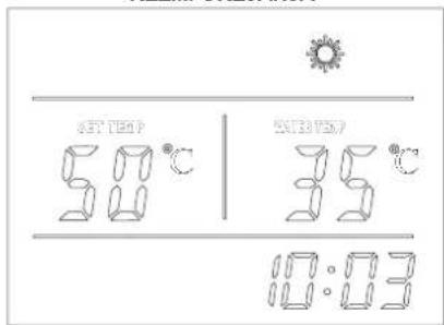
Fig. 01 Fig. 02
Dok toplotna pumpa radi, pritisnite tipku za aktiviranje sistema "Brzo zagrevanje". Na displeju će se pojaviti ikona i električni grejač će početi da radi prema zadanom programu (parametar 3) istovremeno s kompresorom, sve dok se ne dostigne temperatura.

flowchart
graph TD
    A["Adjust Hour/Minute"] --> B["Set Hour/Minute"]
    B --> C["Confirm"]
    D["Timer"] --> E["Set Hour"]
    E --> F["Confirm Hour"]
    F --> G["Set Minute"]
    G --> H["Confirm Minute"]
    H --> I["Save & Exit Cancel"]
    I --> J["Timer"]


flowchart
graph TD
    A["Hand with gear icon"] --> B["Check Parameters A-H"]
    C["Hand with gear icon"] --> D["Check Parameters 1-35"]
Fig. 01 Fig. 02
Fig. 05