
ZIHS7TU - Splitter Zipper - Free user manual and instructions
Find the device manual for free ZIHS7TU Zipper in PDF.

| Product type | Electric log splitter |
| Brand | Zipper |
| Model | ZI-HS7TU |
| Power supply | 220-240 V / 50 Hz, with 0.03 A residual current circuit breaker |
| Operation | Horizontal, two-hand control with trigger lock |
| Safety | Two-hand control, automatic stop if one hand released, protection against accidental restart |
| Splitting capacity | Wood along the grain, dimensions according to technical data (see manual) |
| Operating conditions | Operating temperature +5°C to +40°C, storage -25°C to +55°C, max humidity 50% |
| Maintenance | Check oil level before each use, change hydraulic oil every 150h or 1 year |
| Recommended hydraulic oil | Shell Tellus 22, Mobil DTE 11, Aral Vitam GF 22 or BP Energol HLP-HM 22 |
| Sharpening the splitting wedge | With a fine file to remove burrs or nicks |
| Assembly | Base assembly required (only for ZI-HS7TU) |
| Transport | Wheels and transport handle, loosen vent screw before moving |
| Warranty | 2 years for private use, 1 year for professional use |
| Spare parts | Use only genuine Zipper parts |
| Disposal | Do not dispose of with household waste, follow local regulations |
Frequently Asked Questions - ZIHS7TU Zipper
User questions about ZIHS7TU Zipper
0 question about this device. Answer the ones you know or ask your own.
Ask a new question about this device
Download the instructions for your Splitter in PDF format for free! Find your manual ZIHS7TU - Zipper and take your electronic device back in hand. On this page are published all the documents necessary for the use of your device. ZIHS7TU by Zipper.
USER MANUAL ZIHS7TU Zipper
natural_image
Exterior view of a black and green industrial machine labeled 'ZIPPER' with 'ZI-HS5TN' branding (no other text or symbols visible)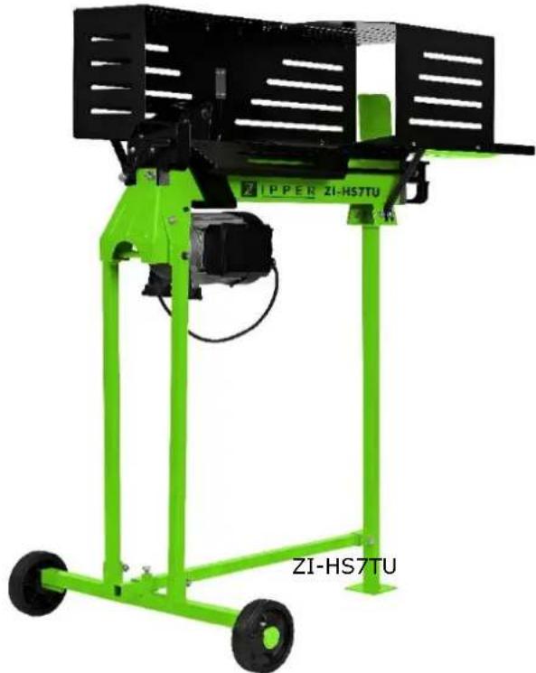
natural_image
Green industrial machine labeled ZI-HS7TU, no visible text or symbols on the device itselfZI-HS5TN / ZI-HS7TU
EAN: 9120039233741 / EAN: 9120039233758
17.1 Safety instructions .... 30
17.2 Residual risks 31
18 ASSEMBLY BASE FRAME (ONLY FOR ZI-HS7TU) 32
19 ASSEMBLY ZI-HS5TN & ZI-HS7TU 34
19.1 Lifting Handle 34
19.2 Log Tray 34
19.3 Steel Guard.... 36
20 TRANSPORT 37
21 OPERATION 37
21.1 Preparatory activities....37
21.1.1 Greasing the splitting wedge.... 37
21.1.2 18.1.2 Bleeding the hydraulic system 38
21.1.3 Fixing the log splitter (ZI-HS5TN only) 38
21.2 Operating the log splitter 38
21.2.1 Freeing jammed logs 40
22 MAINTENANCE 41
22.1 Maintenance schedule 41
22.2 Changing the hydraulic oil 41
22.3 Sharpening the wedge....43
23 DISPOSAL 43
24 TROUBLESHOOTING 43
25 PREDSLOV (SK) 44
26 BEZPEČNOST 45
EN CE-Conformal! - This product complies with the EC-directives.
READ THE MANUAL! Read these operating instructions carefully and familiarize yourself well with the operating elements of your machine in order to be able to operate and maintain it properly and thus prevent damage to man and machine.
EN Do not remove or tamper with any protection or safety devices.
EN Always disconnect device from the mains before starting any repair, maintenance or cleaning!
EN Keep children and bystanders away from the work area!
EN Wear personal protective equipment!
Connect the machine to a 220–240 V/50 Hz power supply with undervoltage, overvoltage, overcurrent protection and a residual current device with a maximum residual current of 0.03 A.
(SK) POZIADAVKY NA ELEKTRICKE PRIPOJENIE
| N° | Bezeichnung / DescriptionNázov / Název /Naziv / NazivMegnevezés / Description / Denominación | N° | Bezeichnung / DescriptionNázov / Název /Naziv / NazivMegnevezés / Description / Denominación |
| 1 | Schutz / guard /kryt / Kryt /Zaščitni pokrov / Štitnik /Védelem / Protection / Protección | 10 | Arbeitstisch / work table /pracovný stôl / Pracovní stůl /Delovna miza / Radni stol /Munkaasztal / Table de travail / Mesa de trabajo |
| 2 | Keil / wedge / klin / Klín / Klin / Klin / Ék / Coin fendeur / Cuňa | 11 | Druckplatte / log pusher /posunovač polien / Posunovač polen /Potiskalo / Potisna ploča /Nyomólemez / Plaque de pression / Placa de presión |
| 3 | Holzablage / log tray /držiak polena / Držák polene /Odlagalna miza / Polica za drvoFatartó / Plateau à bůches / Balda de la madera | 12 | Bedienhebelschutz /control lever guard /poistka ovládacej páky / Pojistka ovládací páky /Zaščita upravljalne ročice / Štitnik ručice za rukovanje /Kezelőfogantyú-védő / Protection de levier de commande /Protección de la palanca de mando |
| 4 | Hebebügel / lifting handle /zdvíhacie madlo / Zvedací madloDvižni ročaj / Drška za podizanje /Emelőkengyel / poignée de levage / Percha de elevación | 13 | Hydr.Steuerhebel /hydr. control lever /páka ovládania hydrauliky / Páka ovládání hydrauliky /Hidravlična krmilna ročica / Hidraulička upravljačka ručica /Hidraulikus vezérlőemelő / Levier de commande hydraulique /Palanca hidr. de control |
| 5 | Holz-Rückhalteplatte / log retaining plates /doska pridržania polena / Deska přidržení polene /Zadrževalna plošča / Ploča za držanje drva /Fa-visszatartó lemez / Plaque de retenue de bois / Placa de retención de madera | 14 | Stützfuß / support leg/oporná noha / Opěrná noha /Podporna noga / Potporna noga /Támasztóláb / pied de support / Pie de apoyo |
| 6 | Drucktaster-Gehäuse / pushbutton box / spínacia skrinka / Spínací skřiň / Tipkalo v ohišju / Kućište tlačne tipke / Nyomógomb-ház / Boîtier bouton poussoir / Carcasa del pulsador | 15 | Motor / motor / motor / Motor / Motor / Motor / Motor /Moteur/ Motor |
| 7 | Schalter / switch / spínač / Spínač / Stikalo / Sklopka / Kapcsoló / Interrupteur / Interruptor | 16 | Räder / wheels / kolieska / Kolečka / Kolesa / Kotači / Kerekek / roues / Ruedas |
| 8 | Entlüftungsschraube / bleeder screw / odvzdušňovacia skrutka / Odvzdušňovací šroub Odzračevalni vijak / Vijak za odzračivanje / Légtelenítő csavar / vis de purge / Tornillo de purga | 17 | Max. Druckbegrenzungs-Schraube /max. pressure limiting screw / skrutka regulácie maximálného tlaku / Šroub regulace maximálního tlaku / Vijak za maksimalno omejitev tlaka / Maks. vijak za smanjene tlaka / Max. nyomáshatároló csavar / Vis de limitation de pression maxi / Tornillo de limitación máx. de presión |
| 9 | Öl-Ablassschraube mit Messstab /oil drain bolt with dipstick / zátka olejovej nádrže s mierkou / Zátka olejové nádrže s měrkou / Vijak za izpust olja z merilno palico / Vijak za ispuštanje ulja s mjernom šipkom / Olajleeresztő csavar mérópálcával / Bouchon de vidange d'huile avec jauge / Tornillo de purga de aceite con varilla de medición |
6 KOMPONENTEN / COMPONENTS /
Komponenty/ Komponenty/ Komponente / Komponente / Összetevők / COMPOSANTS ZI-HS7TU / Componentes

natural_image
Technical line drawing of a mechanical device with two views: top shows a flat panel and bottom shows a wheeled cart (no text or symbols)| N° | Bezeichnung / DescriptionNázov / Název /Naziv / NazivMegnevezés / Description / Denominación | N° | Bezeichnung / DescriptionNázov / Název /Naziv / NazivMegnevezés / Description /Denominación |
| 1 | Maschinen-Korpus (wie ZI-HS5TN)machine-body (as for ZI-HS5TN)korpus stroja (pre ZI-HS5TN)Korpus stroje (pro ZI-HS5TN)Trup stroja (enako kot pri ZI-HS5TN)Tijelo stroja (kao ZI-HS5TN)Géptest (mint ZI-HS5TN)Corps de machine (comme ZI-HS5TN)Cuerpo de la máquina (como ZI-HS5TN) | 2 | Untergestellbase framepodstavecPodstavecPodnožjePostoljeAlsóvázBaseBastidor |
7 VORWORT (DE)
natural_image
Line drawing of a person pushing a wheeled cart (no text or symbols)natural_image
Yellow line drawing of a mechanical device with an arrow and starburst symbol (no text or labels)
natural_image
Illustration of a person operating a machine with a magnified inset showing the internal components (no text or symbols)natural_image
Technical diagram of a machine tool with a diagonal cross mark, showing mechanical components and a warning symbol (no text or labels present)natural_image
Technical line drawing of a machine with a crossed-out blade and mechanical components (no text or symbols)Hinweis:
natural_image
Technical line drawing of a mechanical machine with a large cylindrical roller being processed, showing no text or symbols.natural_image
Technical line drawing of a machine tool with a large cylindrical component being processed, showing motion arrows (no text or symbols)These operating instructions contain information and important notes on commissioning and handling the ZI-HS5TN and ZI-HS7TU wood splitters.
In the following, the usual trade designation of the machine (see cover sheet) in these operating instructions is replaced by the designation "Machine".
The operating instructions are an integral part of the machine and must not be removed. Keep them for later use and attach these instructions to the machine if they are passed on to third parties!
Observe the safety instructions!

Please read these instructions carefully before putting the unit into operation. This will make it easier for you to handle the device properly and will prevent misunderstandings and possible damage. Observe the warning and safety instructions. Disregard can lead to serious injuries.
Due to the constant further development of our products, illustrations and contents may differ slightly. If you notice any errors, please inform us.
Subject to technical changes!
Copyright
© 2018
This documentation is protected by copyright. The constitutional rights thereby reserved! In particular the reprint, the translation and the removal of photos and illustrations will be prosecuted.
The place of jurisdiction shall be the regional court of Linz or the court responsible for 4707 Schlüsslberg.
Customer Support:
Only use the machine in a technically perfect condition and in accordance with its intended use, safety-conscious and aware of the dangers! Have faults which could impair safety rectified immediately!!
The machinery is intended exclusively for the following activities:
For splitting wood in grain direction, with dimensions within the limits specified in the "Technical data" section.
The splitting process of the machine is intended for operation by only one person.
ZIPPER-MASCHINEN accepts no responsibility or warranty for any other use or use beyond this and for any resulting damage to property or injury.
Operating conditions:
The machine is intended for use under the following conditions:
Rel. humidity: max. 50 %
Any improper use or disregard of the information and instructions given in this manual will void all warranty claims and claims for damages against Zipper GmbH.
Improper use:
- Operation of the machine without adequate physical and mental aptitude
- Operating the machine without knowledge of the operating instructions
- Changes in the design of the machine
- Operating the machine under explosive conditions
- Operating the machine outside the specified power range
- Remove the safety markings attached to the machine.
- Modify, circumvent or disable the safety devices of the machine.
17.1 Safety instructions
Warning signs and/or stickers on the machine which are illegible or have been removed must be replaced immediately!
Local laws and regulations may determine the minimum age of the operator and restrict the use of this machine.
In order to avoid malfunctions, damage and adverse health effects, the following additional measures for safe working must be observed UNCONDITIONALLY:
- Do not split soaked wood.
- Only split the wood horizontally in the direction of the grain!
- Do not split wood that contains foreign objects such as nails, cables, etc.
- Never operate the machine outdoors in the rain.
- Choose a level, vibration-free, non-slip surface as the installation location.
- Ensure sufficient lighting conditions at the workplace.
- Keep the working area free of obstacles (e.g. pieces of wood, leftover wood, etc.).
- Before each use, check the machine for its perfect condition (tight fit of hoses and screws, operability of the switch-off devices, etc.).
- Never leave the running machine unattended.
- The machine may only be operated, serviced or repaired by persons who are familiar with it and who have been informed of the dangers arising during this work.
- Although it is possible that several operators could work on the machine (e.g. for loading and unloading), only one person should ever operate the splitting process.
-
As the operator of the machine, make sure that unauthorised persons maintain an appropriate safety distance from the machine and, in particular, keep children away from the machine.
-
Wear suitable work clothing (eye protection, work gloves, safety shoes and close-fitting work protective clothing, never loose clothing, ties, jewellery, etc. - danger of being drawn in!
- Keep your hands away from crevices and cracks that open in the wood.
- Do not reach into the splitting area.
- Do not work on the machine if you are tired, not concentrated or under the influence of medication, alcohol or drugs!
- Do not use the machine in areas where vapours from paints, solvents or flammable liquids represent a potential danger (danger of fire or explosion!).
- Do not smoke in the immediate vicinity of the machine (fire hazard)!
- Make sure that the on/off switch is in the "Off" position before switching on the machine.
- Ensure that the machine is earthed.
- Only use suitable extension cords.
- Always disconnect the unit from the mains before cleaning, maintenance or repair work and secure it against unintentional reconnection.
- Use only intact tools.
17.2 Residual risks
Despite intended use, certain residual risks remain. Due to the design and construction of the machine, hazardous situations may occur which are identified in these operating instructions as follows:

DANGER
A safety instruction designed in this way indicates an imminently hazardous situation which, if not avoided, will result in death or serious injury.

WARNING
A safety instruction designed in this way indicates a potentially hazardous situation which, if not avoided, may result in minor or moderate injury.

NOTICE
A safety notice designed in this way indicates a potentially hazardous situation which, if not avoided, may result in property damage.
Irrespective of all safety regulations, your common sense and appropriate technical suitability/training are and will remain the most important safety factor for error-free operation of the machine. Safe working depends primarily on you!
18 ASSEMBLY BASE FRAME (ONLY FOR ZI-HS7TU)

CAUTION
Due to its high weight, at least two persons are required to mount the log splitter on the base frame
 | A. Disconnect device from the mains:Make sure that the device is not connected to the mains and is protected against unintentional switching on! |
 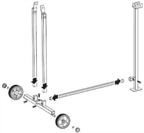 | B. Remove wheels and support leg:Remove wheels (14) and support leg (16).C. Mount the base frame: Assemble the base frame (as shown in the illustration on the left). |
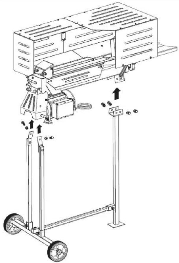 | D. Mounting the machine body: Mount the machine body (as shown in the illustration on the left) on the base frame.E. Follow the steps below to complete assembly! |
19 ASSEMBLY ZI-HS5TN & ZI-HS7TU
19.1 Lifting Handle
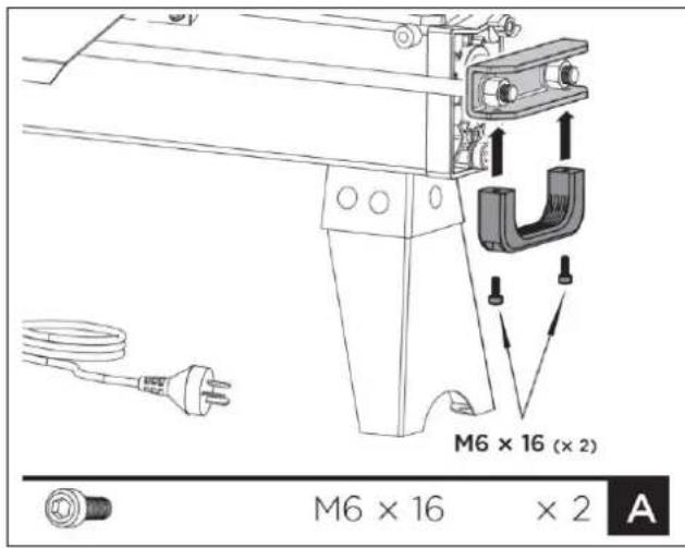
A. Mounting the lifting handle: Attach the lifting handle to the U-bracket with two M6x16 screws.
19.2 Log Tray

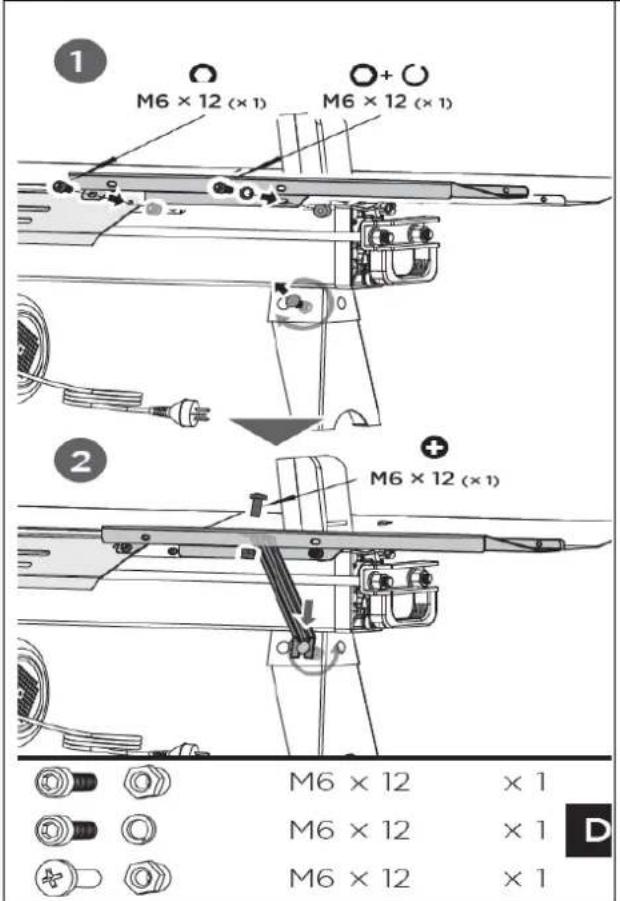
B. Fastening the guard bottom plate:
Mount the guard bottom plate to the rear guide plate and secure it with the two socket head cap screws M6×12 and the lock nuts. Loosen the socket head cap screw and the large washer on the wheel bracket, insert the open end of the support strut 2 between the large washer and the wheel bracket and tighten the screw. Connect the upper end of support strut 2 to the guard bottom plate with a cross recessed pan head screw M6×12 and lock nut M6 and tighten.

C. Log tray right: Align the two mounting holes of log tray right with the holes on the rear of the splitter. Insert one socket head cap screw M6×12 and a spring washer 6 into the mounting hole on the left side, another socket head cap screw M6×12 and lock nut M6 on the right side and tighten both screws firmly (1).
Then loosen the cup head bolt and nut on the left side of the front leg, insert the open end of support strut 1 onto the bolt and tighten the nut.
Connect the upper end of support strut 1 by means of a cross recessed pan head screw M6×12 and lock nut M6 with log tray 1 and tighten the screw (2).
D. Log tray left: Align the two mounting holes of log tray left with the holes on the front of the splitter. Insert a socket head cap screw M6×12 and a spring washer 6 into the mounting hole on the right side, another socket head cap screw M6×12 and lock nut M6 on the left side and tighten both screws firmly.
Then loosen the cup head bolt and nut on the right side of the front leg, insert the open end of support strut 1 onto the bolt and tighten the nut.
Connect the upper end of the support strut 1 with the cross recessed pan head screw M6×12 and the counter nut M6 with log tray 2 and tighten the screw.

E. Connecting log tray right and left: Connect log tray 1 and 2 with two screws M6×12 and lock nuts.
19.3 Steel Guard

A. Attaching front guard plates, left guard plate and rear guard plates: Fix the front guard plate, the left guard plate and two rear guard plates with screws M6×12 and nuts to the log tray and the bottom plate (1).
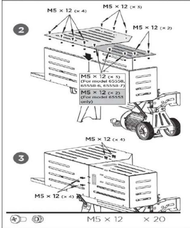
B. Connecting top guard plates / rear guard plates: Mount the two top guard plates with M5×12 bolts and nuts to the vertical plates (2). Connect the top guard plates / rear guard plates with the plate connectors and M5×12 bolts and nuts (3).
20 TRANSPORT
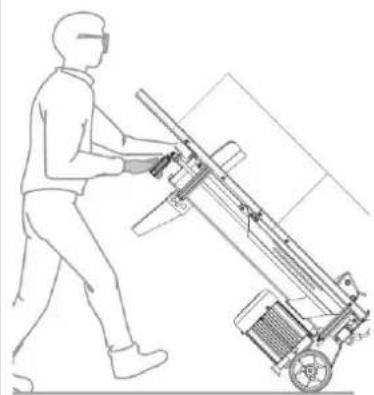
For easier transport over short distances, the log splitter is equipped with two wheels and a transport handle.
| NOTICE | ||
 |  | Before moving the log splitter, make sure that the vent screw is tightened! |
WARNING


When using a crane for lifting (e.g. when loading the splitter onto a truck), attach the hoist only to the intended places - see illustration on the left.
Observe the applicable regulations regarding load securing!
Never hang the hoist on the transport handle!
Never transport the log splitter when loaded!
natural_image
Line drawing of a person pushing a wheeled cart with a sensor or sensor device (no text or symbols)To move the log splitter over short distances, hold it by the transport handle and tilt it slightly - see illustration on the left.
21 OPERATION
CAUTION

Never adjust the pressure relief screw! The maximum splitting force of the log splitter is factory set and the pressure limiting screw is sealed with adhesive to ensure that the pressure does not exceed the preset maximum. Adjustment was made by a qualified mechanic using professional instruments. Unauthorized adjustment of the pressure relief screw may result in serious injury or damage to the machine!
21.1 Preparatory activities
21.1.1 Greasing the splitting wedge
Apply a thin layer of grease to the splitting wedge of your wood splitter before starting work. This will prolong the life of your tool.
21.1.2 18.1.2 Bleeding the hydraulic system
NOTICE

Never forget to loosen the breather screw before starting to operate the log splitter! Otherwise, the air in the system will be released and compressed again and again, which will destroy the seals of the hydraulic circuit and make the log splitter unusable.

To bleed the hydraulic system, loosen the bleed screw a few turns so that the air can flow gently into and out of the oil tank.
The air flow through the oil tank should be visible during operation.
Important: Tighten the air-vent screw before each transport to prevent oil leakage.
21.1.3 Fixing the log splitter (ZI-HS5TN only)

Before putting the wood splitter into operation place it on a 72–85 cm high, stable and level workbench and fasten the support leg with two screws (M8x35) as shown in the picture on the left.
21.2 Operating the log splitter

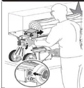
The log splitter is equipped with a two-hand control. The left hand controls the hydraulic control lever, the right hand the pressure switch (see illustration on the left). If one hand is missing, the log splitter "freezes".

natural_image
Illustration of a person operating machinery with an inset close-up showing the motor (no text or symbols present)The trigger-controlled locking device is designed to prevent accidental lowering of the hydraulic control lever.
To operate the hydraulic control lever, first move it forwards and then pull the trigger downwards with your index finger (Fig. left).
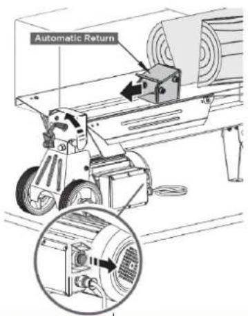 | Only when both hands release the control elements the log pusher automatically returns to its starting position. |
NOTICE

Never press the log splitter for more than 5 seconds, as the oil under pressure will overheat, which may cause the blade to break or damage the machine.
natural_image
Diagram of a machine with a diagonal cross mark and warning symbol, no text or labels present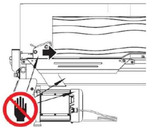
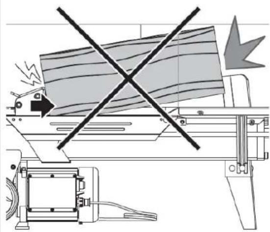
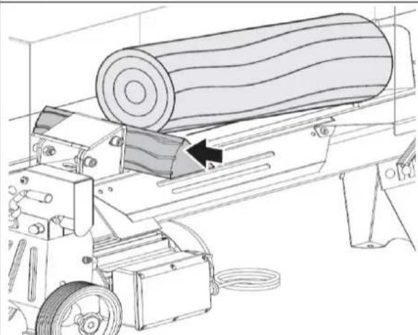
Make sure that the wood does not twist, wobble or slip when splitting. Also note the five-second time limit for pressurizing. If the log cannot be split within this period of time, its hardness exceeds the capacity of the machine. In this case, turn the log by 90^ and try to split the log this way. If this does not work either, the log should be sorted out for safety reasons and to protect the machine.
Always split blocks in the direction of the grain.
To split, place the blocks firmly on the wood support boards and the worktable, and keep your hands away from cracks and tears that open in the wood.
Never try to split two or more pieces of wood at the same time. One of them could be catapulted out and hit and injure you.
21.2.1 Freeing jammed logs
| CAUTION | |
| Do not try to remove trapped wood by hand, either yourself or with the help of other people! You could slip off and/or get trapped and seriously injure yourself. | |
 | Note: Never try to free a jammed logs by hitting it (e.g. with an axe). The hitting could damage or launch the machine and cause accidents. |
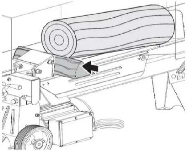 | To free a jammed log:Release both control elements.After the wood slide moves back and comes to a standstill at its starting position, place a wedge under the clamped log.Start the log splitter to move the wedge so that it lies completely under the clamped log. |
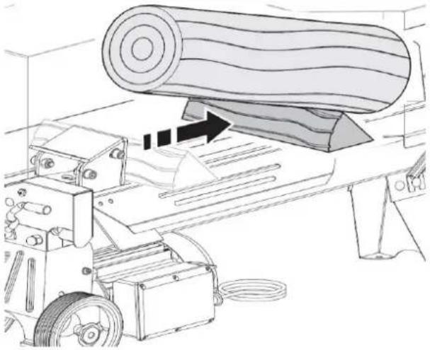 | Repeat above procedure with sharper slope wedge woods until the log is completely freed. |
22 MAINTENANCE
WARNING

Before carrying out any maintenance work, ensure that moving parts are stationary, that the machine is disconnected from the mains and secured against unintentional restarting! Only trained specialist personnel is authorised to carry out repair work on this machine!
22.1 Maintenance schedule
| Activity | ZI-HS5N | ZI-HS7TU |
| Check oil level | Before usage | Before usage |
| Change hydraulic oil | Every 150h or after one year | Every 150 h or after one year |
22.2 Changing the hydraulic oil
NOTICE

Check the oil level regularly. Change the hydraulic oil completely at least once a year. Always dispose of used oil correctly and never dispose of it in household waste or waste water!
The hydraulic system of the log splitter is a closed system with oil tank, oil pump and control valve.
The following oils (or equivalent products) are recommended for the splitter hydraulic transmission system: Shell Tellus 22, Mobil DTE 11, Aral Vitam GF 22 oder BP Energol HLP-HM 22.

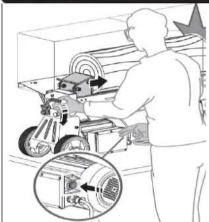
OIL-LEVEL CHECK: If the oil level is too low, the oil pump may be damaged and overfilling may cause the hydraulic system to overheat. Check the oil level regularly with the dipstick - see graphic on the left!
 |  | Waste oils are toxic and must not be discharged into the environment. Contact your local authorities for information on proper disposal. |
| To change oil carry out the following steps:1. Make sure that all moving parts stand still and that the splitter is disconnected from the power source.2. Loosen the oil drain plug with dipstick and remove it. | ||
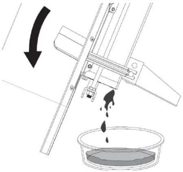 | 3. Turn the log splitter on the support leg over a four litres capacity container and drain the hydraulic oil off. | |
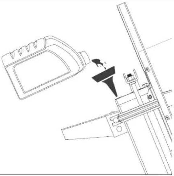 | 4. Then turn the wood splitter to the motor side.5. Top up with fresh hydraulic oil of appropriate specification.6. Make sure that the level of the refilled oil is correct.7. Re-insert the oil drain bolt with the dipstick and tighten.8. Make sure that the bolt is tightened to prevent oil from leaking when the log splitter is returned to the horizontal position. | |
22.3 Sharpening the wedge
The wood splitter is equipped with a re-inforced splitting wedge with a specially treated cutting edge. After a long period of operation and if necessary, sharpen the wedge with a fine file to remove burrs or notches.
23 DISPOSAL
 | Observe the national waste disposal regulations. Do not dispose of the machine, machine components or equipment in residual waste. If necessary, contact your local authorities for information on the disposal options available. If you buy a new machine or an equivalent device from your specialist dealer, he is obliged in certain countries to dispose of your old machine properly. |
 | Waste oils are toxic and must not be discharged into the environment. If necessary, contact your local authorities for information on proper disposal. |
24 TROUBLESHOOTING
| PROBLEM | PROBABLE CAUSE | REMEDY SUGGESTED |
| Failure to split logs | Log is improperly positioned | Refer to “Log Splitter Operation” section for correct log loading. |
| The sizes or hardness of the log exceeds the capacity of the machine | Reduce the log sizes before splitting it on the log splitter. | |
| Wedge cutting edge is blunt | Refer to “Sharpening Wedge” section to sharpen the cutting edge. | |
| Oil leaks | Locate leak(s) and contact the dealer | |
| Unauthorized adjustment was made on max. pressure limiting screw. Lower max. pressure rating was set. | Contact your distributor. | |
| The log pusher moves jerkily, taking unfamiliar noise or vibrating a lot | Lack of hydraulic oil and excessive air in the hydraulic system. | Check oil level for possible oil refilling.Contact your distributor. |
| Oil leaks around cylinder ram or from other points | Air sealed in hydraulic system while operating | Loosen bleed screw by 3-4 rotations before operating the log splitter. |
| Bleed screw is not tightened before moving the log splitter. | Tighten the bleed screw up before moving the log splitter. | |
| Oil drain bolt with dipstick is not tight. | Tighten the oil drain bolt with dipstick. | |
| Hydraulic control valve assembly and / or seal(s) worn | Contact your distributor. |

All repair work on this machine must be carried out by a specialist for this product!

25 PREDSLOV (SK)
Vážený zákazník!
natural_image
Line drawing of a person pushing a cart with a mounted device (no text or symbols)
natural_image
Yellow icon depicting a mechanical device with motion lines and a starburst, no text or symbols present.
natural_image
Illustration of a person operating a mechanical device with a magnified inset showing internal components (no text or symbols)Blokovacie zariadenie riadené spúštou je navrhnuté tak, aby sa zabránilo neúmyselnému spusteniu hydraulické ovládacie páky.
natural_image
Technical diagram of a machine tool with a diagonal line crossing over a shaded area, no text or symbols present.natural_image
Line drawing of a person pushing a cart with a tool, no text or symbols presentnatural_image
Yellow line drawing of a mechanical device with an arrow and starburst symbol (no text or labels)
natural_image
Illustration of a person operating a machine with a magnified inset showing the internal components (no text or symbols)natural_image
Diagram of a machine with a crossed black line indicating no crossing, showing mechanical components and a warning symbol (no text or labels present)Pokyn:
natural_image
Technical line drawing of a machine with a large cylindrical component being processed, showing motion and assembly (no text or symbols)
natural_image
Technical line drawing of a machine tool pressing a large cylindrical component, with no visible text or symbols.C. Montaža odlagalne mize na desni
D. Montaža odlagalne mize na levi
E. Odlagalno mizo cepilnika fiksirajte na desni in levi strani: Spojite odlagalni mizi 1 in 2 s pomočjo dveh vijakov M6×12 in zapornih matic.
natural_image
Line drawing of a person pushing a cart with a mounted device (no text or symbols)natural_image
Illustration of a person operating a machine with a magnified inset showing the internal components (no text or symbols)natural_image
Technical diagram of a machine tool with a diagonal line crossing over a shaded area, no text or symbols present.natural_image
Diagram of a machine with a hammer crossed over a cylindrical component, no text or symbols presentNapotek
natural_image
Technical line drawing of a mechanical conveyor system with a roller being loaded (no text or symbols)natural_image
Technical line drawing of a machine with a large cylindrical component being processed, showing motion arrows (no text or symbols)A. Montaža drške za podizanje: dršku za podizanje dvama vijcima M6x16 pričvrstite na U držač.
54.2 Polica za drvo

B. Montaža podne zaštitne ploče: podnu zaštitnu ploču montirajte na stražnju vodeću ploču i osigurajte ju dvama cilindarskim vijcima M6×12 i protumaticama.
C. Montaža police za drvo na desnoj strani: dva pričvrsna otvora police za drvo s desne strane poravnajte s otvorima na stražnjoj strani stroja za cijepanje drva. Imbus vijak M6×12 i opružni prsten 6 umetnite u otvor za montažu na lijevoj strani, još jedan imbus vijak M6×12 i protumaticu M6 na desnu stranu te čvrsto zategnite oba vijka (1).
Zatim otpustite vijak s plosnatom glavom i maticu na lijevoj strani prednje noge, otvoreni kraj potpore 1 nataknite na vijak i zategnite maticu.
Gornji kraj potpore 1 pomoću križnog vijka M6×12 i protumatice M6 spojite s policom za drvo 1 te čvrsto zategnite vijak (2).

D. Montaža police za drvo na lijevoj strani: dva pričvrsna otvora police za drvo s lijeve strane poravnajte s otvorima na prednjoj strani stroja za cijepanje drva. Imbus vijak M6×12 i elastičnu podlošku 6 umetnite u otvor za montažu na desnoj strani, još jedan imbus vijak M6×12 i protumaticu M6 na lijevoj strani te čvrsto zategnite oba vijka. Zatim otpustite vijak s plosnom glavom i maticu na desnoj strani prednje noge, otvoreni kraj potpore 1 nataknite na vijak i zategnite maticu. Gornji kraj potpore 1 pomoću križnog vijka M6×12 i protumatice M6 spojite s policom za drvo 2 te čvrsto zategnite vijak.

natural_image
Line drawing of a person pushing a wheeled cart with a gear mechanism (no text or symbols)Za pomicanje stroja za cijepanje na kraće udaljenosti uhvatite ga za transportnu dršku i lagano ga nagnite.
56 RAD
OPREZ

natural_image
Pure diagram of a mechanical device with motion arrows and starburst symbol (no text or labels)
natural_image
Illustration of a person operating a mechanical device with a magnified inset showing internal components (no text or symbols)natural_image
Technical diagram of a machine tool with a diagonal line crossing over a shaded area, no visible text or symbolsPazite da se drvo prilikom cijepanje ne okreće, ljulja ili skliže. Osim toga vodite računa o vremenskom ograničavanju od pet sekundi za stavljanje stroja pod tlak.
natural_image
Diagram of a machine with a crossed black line and explosion symbol, no text or labels presentNapomena:
Zaglavljeni drveni blok ne pokušavajte osloboditi udarcima (npr. sjekirom). Udaranjem biste mogli oštetiti stroj ili ga pokrenuti te tako uzrokovati nezgodu.
natural_image
Technical line drawing of a machine with a large cylindrical component being processed, showing motion and assembly (no text or symbols)natural_image
Technical line drawing of a machine tool pressing a large cylindrical component, with no visible text or symbols.- Ponovite gornji postupak s drugim drvenim klinovima sve dok se deblo ne oslobodi.
57 ODRŽAVANJE
UPOZORENJE

natural_image
Line drawing of a person pushing a wheeled cart (no text or symbols)natural_image
Illustration of a person operating a mechanical device with a magnified inset showing internal components (no text or symbols)natural_image
Technical diagram of a machine tool with a diagonal line crossing over a shaded area, no text or symbols present.natural_image
Technical line drawing of a machine with a crossed-out tool and warning symbol (no text or labels)Értesítés:
natural_image
Technical line drawing of a mechanical conveyor system with a roller being loaded (no text or symbols)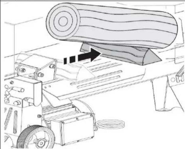
natural_image
Technical line drawing of a machine tool pressing a large cylindrical component, with no visible text or symbols.natural_image
Line drawing of a person pushing a cart with a tool, no text or symbols presentnatural_image
Illustration of a person operating a mechanical device with a magnified inset showing internal components (no text or symbols)natural_image
Technical diagram of a machine tool with a diagonal cross mark, showing mechanical components and a warning symbol (no text or labels present)natural_image
Diagram of a machine with a crossed black line indicating no crossing, showing mechanical components and a warning symbol (no text or labels present)Note:
natural_image
Technical line drawing of a machine with a large cylindrical component being processed, showing motion and assembly (no text or symbols)natural_image
Technical line drawing of a machine tool pressing a large cylindrical component, with no visible text or symbols.natural_image
Line drawing of a person pushing a cart with a tool, no text or symbols presentnatural_image
Pure diagram of a mechanical device with arrows and explosion symbol (no text or labels)

natural_image
Illustration of a person operating a machine with a magnified inset showing internal components (no text or symbols)natural_image
Technical diagram of a machine tool with a crossed-out panel and warning symbol (no text or labels present)natural_image
Diagram of a machine with a crossed black line indicating no crossing, showing mechanical components and a warning symbol (no text or labels present)Aviso:
natural_image
Technical line drawing of a mechanical conveyor system with a roller being loaded (no text or symbols)natural_image
Technical line drawing of a machine tool pressing a large cylindrical component, with no visible text or symbols.
89 ERSATZTEILE / SPARE PARTS / NÁHRADNÉ DIELY/ NÁHRADNÍ DÍLY / REZERVNI DELI / REZERVNI DIJELOVI / PÓTALKATRÉSZEK / PIÈCES DÉTACHÉES / PIEZAS DE RECAMBIO
(EN) With ZIPPER spare parts you use spare parts that are ideally matched to each other. The optimal fitting accuracy of the parts shortens the installation times and increases the service life.
IMP OR TAN T
The installation of other than original spare parts voids the warranty!
So you always have to use original spare parts
When you place a spare parts order please use the service formular you can find in the last chapter of this manual. Always take a note of the machine type, spare parts number and part name. We recommend to copy the spare parts diagram and mark the spare part you need.
You find the order address in the preface of this operation manual.
ERSATZTEILE / SPARE PARTS / NÁHRADNÉ DIELY/ NÁHRADNÍ DÍLY / REZERVNI DELI / REZERVNI DIJELOVI / PÓTALKATRÉSZEK / PIÈCES DÉTACHÉES / PIEZAS DE RECAMBIO
Partslist
| No. | Description | Q'ty |
| 1 | Lever Mount Nut | 1 |
| 2 | Cap Nut M10 | 3 |
| 3 | Lever | 1 |
| 4 | Lever Knob | 1 |
| 5 | Lever Guard | 1 |
| 6 | Customized Nut | 2 |
| 7 | Copper Gasket 10 | 4 |
| 8 | Safety Valve Bolt M8 | 1 |
| 9 | O-ring 5.5×2 | 1 |
| 10 | Snap Washer 6 | 1 |
| 11 | Valve Retract Spring | 1 |
| 12 | O-ring 6×1.5 | 1 |
| 13 | Valve Core Rod | 1 |
| 14 | Sliding Pressure Sensor Sleeve | 1 |
| 15 | Sliding Pressure Sensor Sleeve Sping | 1 |
| 16 | Aluminium Cover ( Rear ) | 1 |
| 17 | O-ring 50×2.65 | 1 |
| 18 | Piston | 1 |
| 19 | Piston Ring 55 | 1 |
| 20 | O-ring 32×3.5 | 1 |
| 21 | Spring | 1 |
| 22 | Stud Bolt | 4 |
| 23 | Hydraulic Cylinder | 1 |
| 24 | Aluminium Cover ( Front) | 1 |
| 25 | Piston Rod Seal 30 | 1 |
| 26 | O-ring 7×1.9 | 1 |
| 27 | Wing Bolt M5×12 | 1 |
| 28 | Wahser Groupware 14 | 1 |
| 29 | Dipstick | 1 |
| 30 | Piston Rod | 1 |
| 31 | Lift Handle | 1 |
| 32 | Screw M6×16 | 2 |
| 33 | Frame Tube | 1 |
| 34 | Lead Plank | 2 |
| 35 | Spring Washer 6 | 6 |
| No. | Description | Q'ty |
| 36 | Screw M6×12 | 12 |
| 37 | Nut M14 | 2 |
| 38 | Flat Wahser 14 | 2 |
| 39 | Hexagon Thin Nut M14 | 2 |
| 40 | Drain Plug | 1 |
| 41 | Wahser Groupware 16 | 1 |
| 42 | Valve Sleeve | 1 |
| 43 | O-ring 10×2 | 5 |
| 44 | Adjusting Screw M5×8 | 1 |
| 45 | Steel Ball 6 | 1 |
| 46 | Pressure Limited Valve Spring | 1 |
| 47 | Adjusting Screw M8×8 | 1 |
| 48 | Log Pusher Connection Weldment | 1 |
| 49 | Plastic Insert 1 | 1 |
| 50 | Plastic Insert 2 | 1 |
| 51 | Log Pusher | 1 |
| 52 | Nut M10 | 4 |
| 53 | Flat Wahser 10 | 5 |
| 54 | Screw M10×25 | 4 |
| 55 | Wheel Cap | 2 |
| 56 | Washer 14 | 2 |
| 57 | Wheel | 2 |
| 58 | Big Flat Washer 6 | 1 |
| 59 | Wheel bracket Weldment | 1 |
| 60 | Bolt M8×55 | 6 |
| 61 | Spring Washer 8 | 9 |
| 62 | Washer 8 | 9 |
| 63 | Gear Pump Cover | 1 |
| 64 | O-ring 10.6×2.65 | 2 |
| 65 | Gear Housing Plate | 1 |
| 66 | Circlip 10 | 2 |
| 67 | Gear Shaft | 1 |
| 68 | Steel Ball 2.5 | 1 |
| 69 | Pump Gear | 2 |
| 70 | Pin 2.5×4 | 1 |
| No. | Description | Q'ty |
| 71 | Washer 6 | 1 |
| 72 | Bolt M5×185 | 3 |
| 73 | Motor Cover | 1 |
| 74 | Seal FB11×26×7 | 1 |
| 75 | Nut M8 | 1 |
| 76 | Screw M8×35 | 1 |
| 77 | Motor | 1 |
| 78 | Motor Fan | 1 |
| 79 | Shaft Circlip A17 | 1 |
| 80 | Shroud | 1 |
| 81 | Spring Washer 5 | 6 |
| 82 | Screw M5×10 | 3 |
| 83 | Leg | 1 |
| 84 | Nut M8 | 5 |
| 85 | Bolt M8×12 | 3 |
| 86 | Cable & Plug | 1 |
| 87 | Bolt M8×16 | 3 |
| 90 | Cable Gland Strain Relief Connector | 1 |
| 89 | Washer 5 | 6 |
| 90 | Screw M4×10 | 11 |
| 91 | Switch Box Cover | 1 |
| 92 | Airproof Underlay | 1 |
| No. | Description | Q'ty |
| 93 | Connection Terminal | 1 |
| 94 | Capacitor | 1 |
| 95 | Switch | 1 |
| 96 | Switch Box | 1 |
| 97 | Waterproof Underlay | 1 |
| 98 | Motor Support Left Shoe | 1 |
| 99 | Motor Support Right Shoe | 1 |
| 100 | Pin 8x24 | 2 |
| 101 | O-ring 46.2x18 | 2 |
| 102 | Sliding Sleeve | 4 |
| 103 | Bolt M8 x30 | 3 |
| 104 | Spring Washer 14(Model E5553's none) | 2 |
| 105 | Screw M6 x12(Machine for assembling Steel Guard) | 13 |
| Screw M6 x12(Machine for assembling Wire Guard) | 5 | |
| 106 | Guard Bottom Plate | 1 |
| 107 | Locknut M6 | 17 |
| 108 | Log Tray 1 | 1 |
| 109 | Support Strut 1 | 2 |
| 110 | Log Tray 2 | 1 |
| 111 | Support Strut 2 | 1 |
Parts List
Parts List Steel Guard
| No. | Description | Q'ty |
| 112 | Top Guard Plate 2 | 1 |
| 113 | Screw M5×12(For model 65558, 65558-6, 65558-7) | 20 |
| Screw M5×12(For model 65553 only) | 19 | |
| 114 | Locknut M5(For model 65558, 65558-6, 65558-7) | 20 |
| Locknut M5(For model 65553 only) | 19 | |
| 115 | Plate Connector | 2 |
| 116 | Top Guard Plate 1 | 1 |
| 117 | Left Guard Plate | 1 |
| 118 | Rear Guard Plate 2 | 1 |
| 119 | Rear Guard Plate 1 | 1 |
| 120 | Front Guard Plate | 1 |
Company ZIPPER Maschinen GmbH grants for mechanical and electrical components a warranty period of 2 years for amateur use; and warranty period of 1 year for professional use, starting with the purchase of the final consumer. In case of defects during this period, which are not excluded by paragraph 3, ZIPPER will repair or replace the machine at its own discretion.
2.) Report:
In order to check the legitimacy of warranty claims, the final consumer must contact his dealer. The dealer has to report in written form the occurred defect to ZIPPER. If the warranty claim is legitimate, ZIPPER will pick up the defective machine from the dealer. Returned shippings by dealers which have not been coordinated with ZIPPER, will not be accepted and refused.
3.) Regulations:
a) Warranty claims will only be accepted, when a copy of the original invoice or cash voucher from the trading partner of ZIPPER is enclosed to the machine. The warranty claim expires if the accessories belonging to the machine are missing.
b) The warranty does not include free checking, maintenance, inspection or service works on the machine. Defects due to incorrect usage of the final consumer or his dealer will not be accepted as warranty claims either. Some examples: usage of wrong fuel, frost damages in water tanks, leaving fuel in the tank during the winter, etc.
c) Defects on wear parts are excluded, e.g. carbon brushes, collection bags, knives, cylinders, cutting blades, clutches, sealings, wheels, saw blades, splitting crosses, riving knives, riving knife extensions, hydraulic oils, oil/air/fuel filters, chains, spark plugs, sliding blocks, etc.
d) Also excluded are damages on the machine caused by incorrect or inappropriate usage, if it was used for a purpose which the machine is not supposed to, ignoring the user manual, force majeure, repairs or technical manipulations by not authorized workshops or by the customer himself, usage of non-original ZIPPER spare parts or accessories.
e) After inspection by our qualified personnel, resulted costs (like freight charges) and expenses for not legitimated warranty claims will be charged to the final customer or dealer.
f) In case of defective machines outside the warranty period, we will only repair after advance payment or dealer's invoice according to the cost estimate (incl. freight costs) of ZIPPER.
g) Warranty claims can only be granted for customers of an authorized ZIPPER dealer who directly purchased the machine from ZIPPER. These claims are not transferable in case of multiple sales of the machine.
4.) Claims for compensation and other liabilities:
The liability of company ZIPPER is limited to the value of goods in all cases. Claims for compensation because of poor performance, lacks, damages or loss of earnings due to defects during the warranty period will not be accepted. ZIPPER insists on its right to subsequent improvement of the machine.
93 ZÁRUČNÉ PODMIENKY (SK)
1.) Záruka:
We monitor the quality of our delivered products in the frame of a Quality Management policy.
Your opinion is essential for further product development and product choice. Please let us know about your:
- Impressions and suggestions for improvement.
- experiences that may be useful for other users and for product design
- Experiences with malfunctions that occur in specific operation modes
We would like to ask you to note down your experiences and observations and send them to us via FAX, E-Mail or by post
service inquiry spare part inquiry guarantee claim
* (Mobil)telefon / (mobile) phone International numbers with country code
Fax
2. Geräteinformationen / tool information
Seriennummer/serial number: ____ *Maschinentype/machine type: ____
Please describe amongst others in the problem: What has cause the problem/defect, what was the last activity before you noticed the problem/defect? For electrical problems: Have you had checked you electric supply and the machine already by a certified electrician?
3. Bitte beachten
/ Additional information
INCOMPLETELY FILLED SERVICE FORMS CANNOT BE PROCESSED! FOR GUARANTEE CLAIMS PLEASE ADD A COPY OF YOUR ORIGINAL SALES / DELIVERY RECEIPT OTHERWISE IT CANNOT BE ACCEPTED. FOR SPARE PART ORDERS PLEASE ADD TO THIS SERVICE FORM A COPY OF THE RESPECTIVE EXPLODED DRAWING WITH THE REQUIRED SPARE PARTS BEING MARKED CLEARLY AND UNMISTAKABLE. THIS HELPS US TO IDENTIFY THE REQUIRED SPARE PARTS FASTLY AND ACCEL- LERATES THE HANDLING OF YOUR INQUIRY.


- ZI-HS5TN / ZI-HS7TU
- ASSEMBLY BASE FRAME (ONLY FOR ZI-HS7TU) 32
- ASSEMBLY ZI-HS5TN & ZI-HS7TU 34
- TRANSPORT 37
- OPERATION 37
- MAINTENANCE 41
- (SK) POZIADAVKY NA ELEKTRICKE PRIPOJENIE
- KOMPONENTEN / COMPONENTS /
- VORWORT (DE)
- Hinweis:
- Observe the safety instructions!
- Copyright
- Customer Support:
- ZIPPER-MASCHINEN accepts no responsibility or warranty for any other use or use beyond this and for any resulting damage to property or injury.
- Operating conditions:
- Improper use:
- Safety instructions
- Warning signs and/or stickers on the machine which are illegible or have been removed must be replaced immediately!
- Local laws and regulations may determine the minimum age of the operator and restrict the use of this machine.
- Residual risks
- DANGER
- WARNING
- NOTICE
- ASSEMBLY BASE FRAME (ONLY FOR ZI-HS7TU)
- CAUTION
- ASSEMBLY ZI-HS5TN & ZI-HS7TU
- Lifting Handle
- Log Tray
- Fastening the guard bottom plate:
- Steel Guard
- TRANSPORT
- OPERATION
- Preparatory activities
- Greasing the splitting wedge
- 18.1.2 Bleeding the hydraulic system
- Fixing the log splitter (ZI-HS5TN only)
- Operating the log splitter
- Freeing jammed logs
- MAINTENANCE
- Maintenance schedule
- Changing the hydraulic oil
- Sharpening the wedge
- DISPOSAL
- TROUBLESHOOTING
- PREDSLOV (SK)
- Vážený zákazník!
- Pokyn:
- Montaža odlagalne mize na desni
- Montaža odlagalne mize na levi
- Napotek
- Polica za drvo
- RAD
- OPREZ
- Napomena:
- ODRŽAVANJE
- UPOZORENJE
- Értesítés:
- Note:
- Aviso:
- IMP OR TAN T
- The installation of other than original spare parts voids the warranty!
- ERSATZTEILE / SPARE PARTS / NÁHRADNÉ DIELY/ NÁHRADNÍ DÍLY / REZERVNI DELI / REZERVNI DIJELOVI / PÓTALKATRÉSZEK / PIÈCES DÉTACHÉES / PIEZAS DE RECAMBIO
- 2.) Report:
- 3.) Regulations:
- 4.) Claims for compensation and other liabilities:
- ZÁRUČNÉ PODMIENKY (SK)
- 1.) Záruka:
- Geräteinformationen / tool information
- Bitte beachten
- / Additional information
Brand : Zipper
Model : ZIHS7TU
Category : Splitter