
ZIHS22EZ - Splitter Zipper - Free user manual and instructions
Find the device manual for free ZIHS22EZ Zipper in PDF.

| Product Type | Log splitter |
| Model | ZI-HS22EZ (ZIHS22EZ) |
| Brand | Zipper |
| Electrical Supply (motor version) | 400 V three-phase, 50 Hz, 16 A max, 5 conductors (3P+N+PE) |
| Power Take-Off (PTO) Supply | 540 min⁻¹, power ~12 kW, standard category 1 shaft (1 3/8", 6 splines) |
| Dimensions | Not specified in the manual; refer to mounting dimensions |
| Weight | Not specified; estimated between 150 and 250 kg |
| Split Force | Variable depending on lever: max at mid-stroke position, max speed at low position |
| Split Capacity | Wood along the grain, dimensions not specified |
| Recommended Hydraulic Oil | Shell Tellus 22, Mobil DTE 11, Aral Vitam GF 22 or BP Energol HLP-HM 22 |
| Transmission Oil | SAE90 (for models with transmission) |
| Oil Reservoir | Closed system; check level regularly |
| Mounting | 3-point hitch for tractor or wheels for standalone version |
| Start-Up | Bleed air from hydraulic circuit, check rotation direction, grease wedge |
| Main Functions | Splitting logs, lifting logs (optional), manual retraction of wedge |
| Regular Maintenance | Change hydraulic oil 1x/year; change transmission oil after 25h then 250h; sharpen wedge |
| Safety | Safety switch on PTO shaft, protective cover, safety hook, emergency stop |
| Spare Parts and Repairability | Original Zipper parts recommended; 2 years warranty non-commercial, 1 year commercial |
| Operating Conditions | Temperature +5°C to +40°C, humidity max 50%, altitude up to 1000 m |
| Intended Use | Splitting wood along the grain, by one person |
Frequently Asked Questions - ZIHS22EZ Zipper
User questions about ZIHS22EZ Zipper
0 question about this device. Answer the ones you know or ask your own.
Ask a new question about this device
Download the instructions for your Splitter in PDF format for free! Find your manual ZIHS22EZ - Zipper and take your electronic device back in hand. On this page are published all the documents necessary for the use of your device. ZIHS22EZ by Zipper.
USER MANUAL ZIHS22EZ Zipper
natural_image
Green handheld industrial machine with black components and a labeled part (ZI-HS EAN), no visible text or symbols on the device itself.ZI-HS16E
EAN: 9120039233697

natural_image
Green industrial machine with black components and mechanical arms (no visible text or symbols)ZI-HS22EZ
EAN: 9120039233703

natural_image
Green industrial machine with hydraulic cylinder and wheels (no visible text or symbols)ZI-HS30EZ
EAN: 9120039233710

natural_image
Green industrial machine with black components and a handle, no visible text or symbolsZI-HS30Z
EAN: 9120039233727
13.2 Residual risks 31
14 ASSEMBLY 32
14.1 ZI-HS16E 32
16.1 Preparatory activities 41
16.1.1 Greasing the splitting wedge.... 41
16.1.2 Bleeding the hydraulic system 41
16.1.3 Checking the rotation direction of the motor - for models ZI-HS16E, ZI-HS22EZ and ZI-HS30EZ only.... 41
16.2 Operating 42
16.2.1 Splitting lever 42
16.2.2 Splitting 42
16.2.3 Free a jammed log 43
17 MAINTENANCE 44
17.1 Maintenance Schedule....44
17.2 Replacing Oil 44
17.3 Sharpening Wedge 45
17.4 Gearbox Lubrication- for models ZI-HS22EZ and ZI-HS30(E)Z only.... 45
18 DISPOSAL 46
19 TROUBLESHOOTING 46
20 PREFACIO (ES) 47
21 SEGURIDAD 48
EN CE-Conformal! - This product complies with the EC-directives.
READ THE MANUAL! Read these operating instructions carefully and familiarize yourself well with the operating elements of your machine in order to be able to operate and maintain it properly and thus prevent damage to man and machine. iLEA EL MANUAL! Lea el manual de uso y mantenimiento cuidadosamente
EN Keep your workspace tidy! Untidiness may result in accidents.

EN Do not remove or tamper with any protection or safety devices.
EN Dispose used oil in an environmental-friendly way!
EN Do not use in the rain!
EN No smoking or open flames!
EN Danger! Keep clear of moving parts!
EN Do not remove jammed logs by hands!
EN Before starting any repair, maintenance or cleaning always disconnect device from the mains!
EN Avoid injury from the movement of the splitting blade.
EN Keep children and bystanders away from the work area!
EN Wear personal protective equipment!
- Holzspalter-Rahmen & Antriebseinheit / log splitter frame & power unit / cuerpo de la astilladora y motor / Cadre fendeur de bois et unité d'entraînement
- Schutzarm / guard arm / brazo protector / Bras de protection
- Stammheber / log lift / elevación del tronco / Dispositif pour soulever des grumes
- Rückhalte-Haken / retaining hook /gancho de retención / Crochet de retenue
- Räder / wheels /ruedas / Roues
- Radachse / wheel shaft /eje de la rueda / Axe de roue
- Stützrad / support wheel /rueda de apoyo / Roue de support
- Bedienungsanleitung / operator's manual /manual de instrucciones / Mode d'emploi
- Beutel mit Kleinteilen, inklusive / hardware bag including / bolsa de accesorios, incluidos / Sachet de petites pièces, inclus
3.1.2 ZI-HS22EZ / ZI-HS30(E)Z

1 Holzspalter-Rahmen & Antriebseinheit /
log splitter frame & power unit /
cuerpo de la astilladora y motor / Cadre fendeur de
bois et unité d'entraînement
2. Schutzarm / guard arm / brazo protector / Bras de protection
3. Stammheber / log lift / elevación del tronco / Dispositif pour soulever des grumes
4. Rückhalte-Haken / retaining hook /gancho de retención / Crochet de retenue
5. Zapfwellen-Abdeckung / PTO cover / cubierta PTO / Couvercle d'arbres de prise de force
6. Stützrad / support wheel /rueda de apoyo / Roue de support
8. Bedienungsanleitung / operator's manual /manual de instrucciones / Mode d'emploi
9. Beutel mit Kleinteilen, inklusive / hardware bag including / bolsa de accesorios, incluidos / Sachet de petites pièces, inclus :
3.2 Technische Daten / Technical Data / Ficha técnica / Données techniques
| ZI-HS16E | ZI-HS22EZ | ZI-HS30EZ | ZI-HS30Z | |
| Motorleistung /engine power /potencia del motorPuissance du moteur | S6 40% IP544500W | S6 40% IP545100W | S6 40% IP545500W | — |
| Spannung / voltage /Voltaje / Tension | 400 V (~3p)/ 50 Hz | 400 V (~3p)/ 50 Hz | 400 V (~3p)/ 50 Hz | — |
| Spaltgut-Durchmesserlog size capacitycapacidad de troncoDiamètre du bois à fendre: ∅ | 8-30 cm | 8-35 cm | 8-40 cm | 8-40 cm |
| Spaltgut-Längelog size capacity: lengthcapacidad de tronco: largoLongueur du bois à fendre | 56-110 cm | 56-110 cm | 56-110 cm | 56-110 cm |
| Maximale Spaltkraftmaximum forcefuerza de división máximaPuissance de fendage maximale | 16 t | 22 t | 30 t | 30 t |
| Hydraulikdruckhydraulic pressurepresión hidráulicaPression hydraulique | 24,89 MPa | 24,73 MPa | 23,46 MPa | 23,46 MPa |
| Hydrauliköl-Kapazitäthydraulic oil capacitydepósito de aceite hidráulicoCapacité d'huile hydraulique | 18 l | 24 l | 30 l | 30 l |
| ZapfwellendrehzahlPTO shaft speedvelocidad del eje PTOVitesse de prise de force | - | 540 U/min | 540 U/min | 540 U/min |
| Verfahrweg Spaltkeilram travelrecorrido cuña astilladoraCourse du coin à refendre | 94,8 cm | 94,8 cm | 94,8 cm | 94,8 cm |
| Vorwärtsgeschwindigkeitspeed forwardvelocidad de avanceVitesse d'avance | 14,2 cm/s | 10,5 cm/s | 12,5 cm/s | 8,1 cm/s |
| Vor. Geschw. bei Lastspeed forward under loadvelocidad de avance bajo cargaVitesse d'avance en charge | 4,6 cm/s | 4,3 cm/s | 3,7 cm/s | 2,4 cm/s |
| Rückwärtsgeschwindigkeitspeed backwardvelocidad de retrocesoVitesse de recul | 6,4 cm/s | 7,5 cm/s | 6,7 cm/s | 4,4 cm/s |
| Lärmdruckpegel / sound pressure levelnivel presión sonoraNiveau de pression acoustique (LpA) | ≤ 80 db(A) | ≤ 80 db(A) | ≤ 80 db(A) | ≤ 80 db(A) |
| Vibrationspegel /vibrationVibración / Seuil de vibrations | < 2,5 m/s2 | < 2,5 m/s2 | < 2,5 m/s2 | < 2,5 m/s2 |
| Länge / lengthLargo / Longueur | 105 cm | 105 cm | 105 cm | 105 cm |
| Breite / widthAncho / Largeur | 155 cm | 170 cm | 170 cm | 170 cm |
| Höhe / heightAlto / Hauteur | 250 cm | 250 cm | 250 cm | 250 cm |
| Gewicht / weightPeso / Poids | 258 kg | 320 kg | 373 kg | 333 kg |
With the 3-phase 400 Volt / 50Hz motor, the log splitter should be connected to a standard 400 V ± 10% / 50 Hz ± 1% mains supply. The electrical supply must be equipped with protective devices against undervoltage, overvoltage, overcurrent and with a residual current protective device with a maximum rated residual current of 0.03 A. The mains connection cable must be connected to the mains supply.
Mains connection cable and extension cable must be 5-core = 3P + N + PE (3/N/PE). The mains connection must be fused with a maximum of 16 A. Rubber power cables must comply with EN60245 and be marked with the symbol "H 07 RN". The marking of the cables is required by law.
| N° | N° | ||
| 1 | Zylinder /cylinderCilindro /Cylindre | 11 | Stecker /plugEnchufe / Prise |
| 2 | Hydraulikleitung / hydraulic hose tubo hidráulico /Conduite hydraulique | 12 | Stammfixier-Kralle/ log fixing clawgancho de fijación del tronco / Griffe de maintien des grumes |
| 3 | Motor / motor / motor / Moteur | 13 | Steuerhandgriff 1 / control handle 1palanca de control 1 /Poignée de commande 1 |
| 4 | Pumpe 1 / pump 1 / bomba 1 /Pompe 1 | 14 | Steuerhandgriff 2 / control handle 2palanca de control 2 / Poignée de commande 2 |
| 5 | Stützrad / support wheelRoue de support / rueda de apoyo | 15 | Hubkette / lift chain cadena de elevación / Chaîne de levage |
| 6 | Zapfwellenstummel / PTO stubBout de prise de force / conexión PTO | 16 | Sicherungshaken / retaining hookgancho de retención / Crochet de securité |
| 7 | Rad / wheelRueda / Roue | 17 | Stammheber / log liftelevación del tronco / Dispositif poursoulever des grumes |
| 8 | Pumpe 2 / pump 2 bomba 2 / Pompe 2 | 18 | Spaltkeil / splitting wedgecuña astilladora / Couteau diviseur |
| 9 | Basisgestell / base frameBase / Châssis de base | 19 | Gefederter Einfahrhebel /spring-loaded retract control leverpalanca de control de retracción por muelleLevier de rétractation à ressort |
| 10 | Schutzarm / guard armbrazo protector /Bras de protection | 20 | L-Bolzen / l-pinperno L / Goupille en L |
4 VORWORT (DE)
natural_image
Technical line drawing of a mechanical device with no visible text or symbolsnatural_image
Technical line drawing of a vehicle suspension system with mechanical components and a magnified inset showing internal components (no text or labels)
natural_image
Technical diagram of a mechanical component with mounting holes and a central circular feature, labeled 'P' (no text or symbols beyond label)Phasenwender
This operating manual contains information and important notes on commissioning and handling the wood splitter models ZI-HS16E / ZI-HS22EZ / ZI-HS30EZ / ZI-HS30Z.
In the following, the usual trade name of the device (see cover sheet) in this operating manual is replaced by the designation "machine".
The operating manual is part of the machine and must not be removed. Keep it for future reference and include this manual with the machine if it is passed on to third parties!
Observe the safety instructions!

Read these instructions carefully before use. This facilitates proper handling and prevents misunderstandings and possible damage. Follow the warnings and safety instructions. Failure to do so may result in serious injury.
Due to the constant further development of our products, illustrations and contents may differ slightly. If you find any errors, please inform us.
Subject to technical changes!
Copyright
© 2018
This documentation is protected by copyright. The thereby constitutional rights remain reserved – in particular, the reprint, translation and extraction of photos and illustrations will be prosecuted.
The place of jurisdiction is the regional court Linz or the court responsible for 4707 Schlüsslberg.
Customer support:
Only use the machine in a technically perfect condition and in accordance with its intended use, safety-conscious and aware of the dangers! Have faults which could impair safety rectified immediately!
The machine is intended exclusively for the following activities:
For splitting wood in the direction of the grain, with dimensions that are within the limits specified in the "Technical data" section.
The splitting process of the machine is intended for operation by only one person.
ZIPPER-MASCHINEN assumes no responsibility or warranty for any other use or use beyond this and for any resulting damage to property or injuries.
Operating conditions:
The machine is intended for use under the following conditions:
| Humidity: | max. 50 % |
| Temperature | +5°C to +40°C |
| Altitude above sea level | up to 1.000 m |
Any improper use or disregard of the information and instructions given in this manual will invalidate all warranty claims and claims for damages against Zipper GmbH.
Unauthorised use:
• Operation of the machine without adequate physical and mental aptitude
- Operating the machine without knowledge of the operating instructions
• Changes in the design of the machine
- Operating the machine under explosive conditions
- Operating the machine outside the specified power range
- Remove the safety markings attached to the machine.
- Modify, circumvent or disable the safety devices of the machine.
13.1 Safety instructions
Warning signs and/or stickers on the machine which are illegible or have been removed must be replaced immediately!
Local laws and regulations can determine the minimum age of the operator and restrict the use of this machine!
In order to avoid malfunctions, damage and health impairments, the following measures for safe working must also be observed:
- Do not split soaked wood.
- Only split the wood upright in the direction of the grain!
- Do not split wood that contains foreign objects such as nails, cables, etc.
- Operate the machine only in well-ventilated rooms or outdoors.
- Never operate the machine outdoors when it is raining.
- Choose a level, vibration-free, non-slip surface as the installation location.
- Ensure sufficient lighting conditions at the workplace.
- Keep the working area free of obstacles (e.g. pieces of wood, leftover wood, etc.).
- Before each use, check the machine for its perfect condition (tight fit of hoses and screws, operability of the switch-off devices, etc.).
- Never leave the running machine unattended.
- The machine may only be operated, serviced or repaired by persons who are familiar with it and who have been informed of the dangers arising during this work.
- Although it is possible that several operators could work on the machine (e.g. for loading and unloading), only one person should ever operate the splitting process.
- As the operator of the machine, make sure that unauthorised persons maintain an appropriate safety distance from the machine and, in particular, keep children away from the machine.
- Wear suitable work clothing (eye protection, work gloves, safety shoes and close-fitting work protective clothing, never loose clothing, ties, jewellery, etc. - danger of being drawn in!
- Keep your hands away from crevices and cracks that open in the trunk.
- Do not reach into the splitting area.
- Do not work on the machine if you are tired, not concentrated or under the influence of medication, alcohol or drugs!
- Keep the unit away from potential ignition sources such as pilot lights and/or open flames (danger of fire and explosion).
- Do not smoke in the immediate vicinity of the machine.
• Make sure that the on/off switch is in the "Off" position before switching on the machine. - Make sure that the machine is earthed if necessary.
- Only use suitable extension cords.
- Before cleaning, maintenance or repair work, always disconnect the device from the power or drive source and secure it against unintentional reconnection.
- Only use intact tools.
13.2 Residual risks
Despite proper use, certain residual risks remain. Due to the design and construction of the machine, hazardous situations may occur which are indicated as follows in these operating instructions:

DANGER
A safety instruction of this type indicates an imminently dangerous situation which, if not avoided, will result in death or serious injury.

WARNING
This type of safety information indicates a potentially hazardous situation which, if not avoided, could result in serious injury or even death.

CAUTION
This safety information indicates a potentially hazardous situation which, if not avoided, may result in minor or moderate injury.

NOTICE
Such a safety notice indicates a potentially hazardous situation which, if not avoided, may result in property damage.
Irrespective of all safety regulations, your common sense and corresponding technical suitability and/or training remain the most important safety factor for fault-free operation of the machine.
Safe working depends on you!
14 ASSEMBLY
14.1 ZI-HS16E
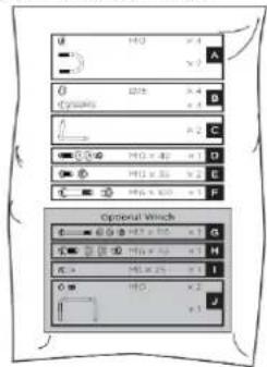
 | A. Attaching the wheel shaft: Attach the wheel shaft with U-bolts and lock nuts to the splitter. |
 | |
 | B. Mounting the wheels: Place a washer onto the axle, then a wheel followed by another washer, and secure with a cotter pin. Repeat procedure for the other side. |
 | |
 | C. Expanding the wedge ram: Keeping the support stand against the wedge, lower both control handles to expand wedge ram (1). Insert the L pins to secure the cylinder to the splitter (2). Lock the pins into the spring tabs (3,4). |
 | |
 | D. Removing the support stand: Release both control handles to retract the wedge ram. Remove the support stand. |
 | E. Mounting the guard arm: Align the hole and locking pin of the guard arm with the mount bracket. Secure the guard arm with a M10 × 40 hex bolts, two washers and a nut from the hardwar bag. |
  | F. Mounting the retaining hook: Position the retaining hook onto the frame and secure with two M10×35 hex bolts and nuts. |
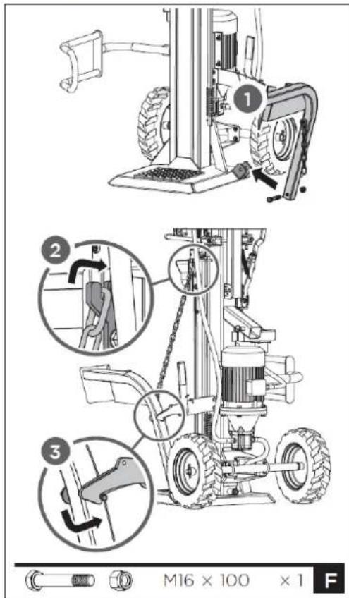
G. Mounting the log lift: Position the log lift inside the mounting bracket and align with mounting bracket holes. Secure with a M16×100 hex bolt and nut. Hook the lift chain to wedge slide guide.
natural_image
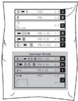
Technical line drawing of a mechanical device with gears and shafts, no visible text or symbolsA. Mounting the hookup pins: Secure the hookup pins to hitchbracket.

B. Attaching the PTO cover: Attach the PTO cover with two M10 nuts to the splitter.

NOTICE
Motor does not start if PTO cover not attached (safety switch)
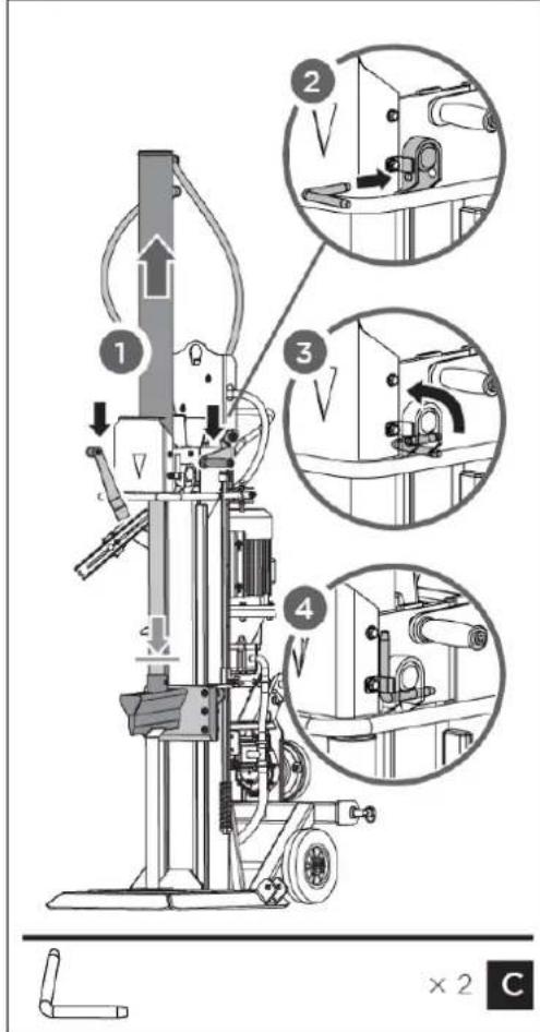
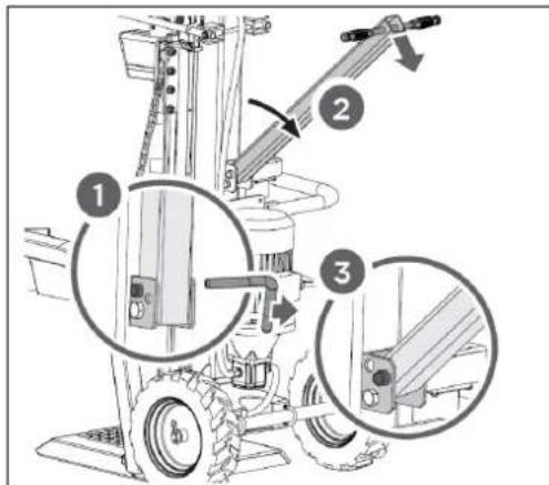
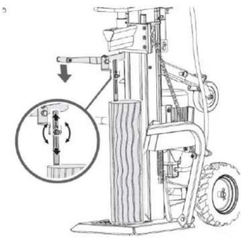
C. Expanding the wedge ram: Keeping the support stand against the wedge, lower both control handles to expand wedge ram. Insert the L pins to secure the cylinder to the splitter. Lock the L pins into the spring tabs.
 | D. Removing the support stand: Release both control handles to retract the wedge ram. Remove the support stand. |
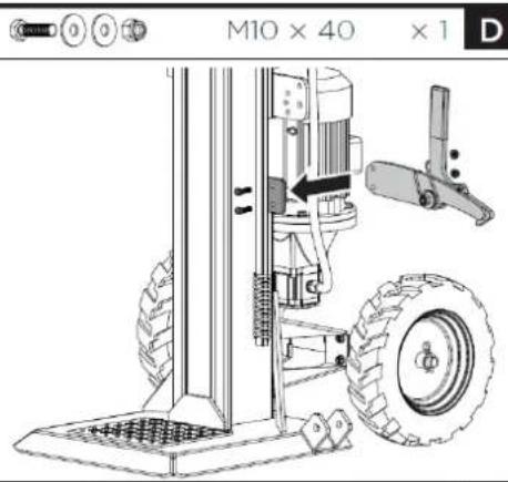
 | E. Mounting the guard arm: Align the hole and locking pin of the guard arm with the mount bracket. Secure the guard arm with a M10 × 40 hex bolts, two washers and a nut from the hardwar bag. |
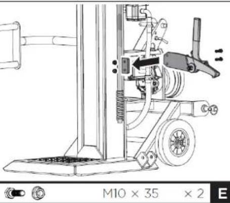 | F. Mounting the retaining hook: Position the retaining hook onto the frame and secure with two M10×35 hex bolts and nuts. |
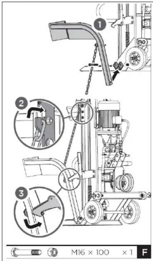
G. Mounting the log lift: Position the log lift inside the mounting bracket and align with mounting bracket holes. Secure with a M16×100 hex bolt and nut. Hook the lift chain to wedge slide guide.

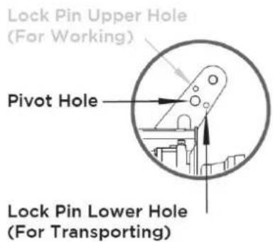
H. Mounting the support wheel: Mount the support wheel with the lock pin and pivot bolt.
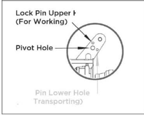
Insert the lock pin into the upper hole for working and insert it into the lower hole for transporting.
14.2.1 Coupling the PTO shaft
The log splitter can be driven by means of a PTO shaft which transmits the torque from the tractor during normal operation. (Attention: The PTO shaft is not included in the scope of delivery of the log splitter!). The PTO end of the gearbox has a diameter of 34.8 mm (1 3/8") and a hexagonal connection (standard category 1 PTO).

NOTICE
The PTO shaft represents a potential source of danger. Read the operating instructions supplied with the PTO shaft carefully and in particular pay attention to the safety instructions.

natural_image
Technical line drawing of a vehicle suspension system with mechanical components and a magnified inset showing internal components (no text or labels)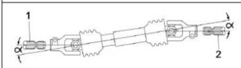
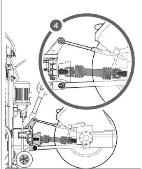
- Back the rear of the tractor toward the log splitter Position the lower draft arms close enough to the splitter's hookup pins. Apply the tractor parking brake and turn the engine off.
- Block the rear wheels on both sides in front and back with wedges or other appropriate objects.
- Remove the plastic self-locking sleeve of the log splitter and hang it on the PTO shield.
-
Slide the lower draft arms onto the splitter hookup pins and secure withholding pins.
-
Position the upper draft arm inside the mounting bracket and align with the mounting bracket holes. Insert the hitch pin to secure the upper draft arm in place.
-
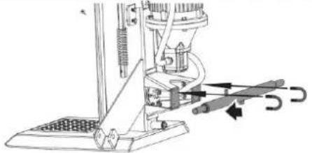
Slide the PTO driveshaft over the PTO shaft ends on the gearbox and tractor respectively. Press inward on the spring pins that are located on both ends of the PTO driveshaft. Continue sliding the driveshaft over the PTO shaft ends until the spring pins pop out and lock into the detents in the PTO shaft ends.
-
Secure the PTO shaft safety chains to stationary parts of the log splitter and tractor to stop the guard from turning.
Note: Keep splitter PTO shaft end (1) and tractor PTO shaft end (2) parallel as viewed from above and from the sides of the shafts. Maintain PTO shaft joint angles ( ) as small as possible.
14.2.2 Uncoupling the PTO shaft

NOTICE
There is a motor contact device inside the self-locking sleeve. When the sleeve removed, the motor cannot start. So the machine only works when it is connected to motor only or to PTO only.
To uncouple the PTO shaft proceed as follows:
- Reduce tractor throttle to IDLE before disengaging PTO. Apply the parking brake and turn off the engine.
- Pull up the locking pins and slide the lower draft arms of the tractor off from the splitter hookup pins.
- Pull up the hitch pin and slide the upper draft arm off from the mounting bracket.
- Release the spring pins located on both ends of the driveshaft. Slide the PTO driveshaft off from the PTO shaft ends on the gearbox and tractor respectively.
- Mount the plastic self-locking sleeve.
15 TRANSPORT
15.1 ZI-HS16E
For easier transport, the log splitter has two wheels, a support wheel and a transport handle.
| NOT ICE | ||
| When using a crane for lifting, attach the crane hook only to the intended lifting point (a) - see illustration on the left.Never attach the crane hook to the transport handle (b)!Before moving the log splitter, make sure that the cover on the oil tank is firmly closed!To move the splitter, grasp the handle (b) and carefully tilt machine backwards! | ||
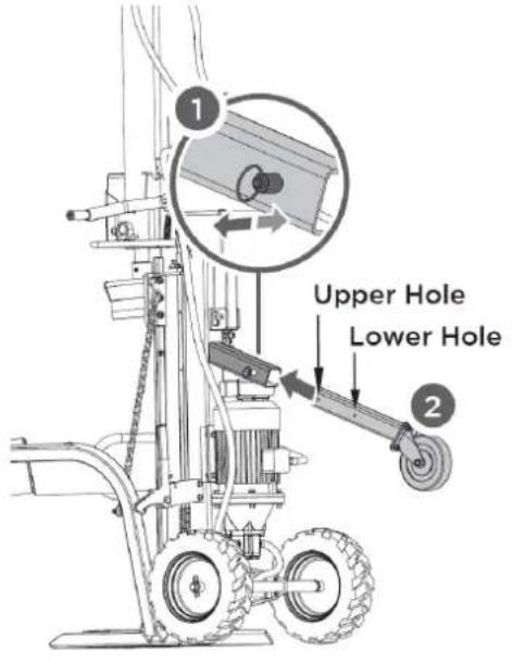 | A. Moving support wheel to the transport position: To mount the support wheel, remove the spring bolt and push the square tube with the support wheel into the holder (1). Then select the appropriate hole and fix the square tube in the desired position using the spring bolt (2). |
B. Fold out the transport handle: The transport handle is normally fixed in an upright position. To transport the log splitter, the transport handle must be folded out as shown in the illustration on the left. To unfold, release the pin (1), unfold the transport handle (2) and fix it in the unfolded position using the pin (3).
The 3-point attachment to the tractor makes the log splitter easy to move. Before transport, make sure that the log splitter is correctly and securely attached to the tractor and that the safety chains are in place. Make sure that the splitter is raised high enough to avoid obstacles during transport. Never transport the log splitter when the PTO shaft switched on! In driving situations, e.g. when turning, parking or passing crossings, take into account the excess length caused by the attached log splitter.
NOTICE
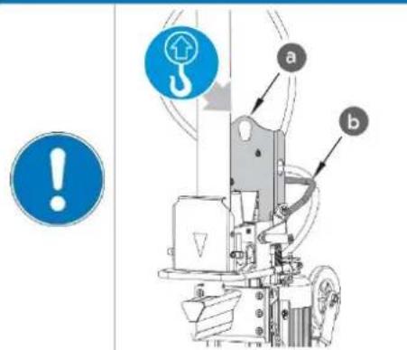
- When using a crane for lifting, attach the crane hook only to the intended lifting point (a) - see illustration on the left.
- Never attach the crane hook to the transport handle (b)!
- Before moving the log splitter, make sure that the cover on the oil tank is firmly closed!
• To move the log splitter, grasp the transport handle (b) and carefully tilt it back!
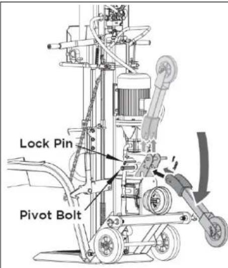
A. Positioning the transport wheel: Pull out the lock pin, turn down the support wheel to the transporting position.
B. Insert the lock pin to the lower hole and fix it by R-pin!
16 OPERATION
16.1 Preparatory activities
16.1.1 Greasing the splitting wedge
Apply a thin layer of grease to the splitting wedge of your log splitter before starting work. This will prolong the life of the tool.
16.1.2 Bleeding the hydraulic system
NOTICE

Never forget to loosen the oil tank cap! Otherwise the air in the system will be compressed and released again and again, which will destroy the seals of the hydraulic circuit and make the log splitter unusable.
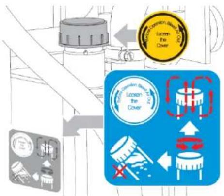
Vent the hydraulic system before starting the log splitter. To do this, loosen the cover of the hydraulic oil tank by a few turns until the air can flow in and out gently. The air flow through the oil tank should be visible during operation. To prevent oil from leaking out, the oil tank cover must be tightly closed before each transport!
16.1.3 Checking the rotation direction of the motor - for models ZI-HS16E, ZI-HS22EZ and ZI-HS30EZ only
NOT ICE

Never run the motor in the wrong rotation direction. This will damage the pump and void the warranty.
natural_image
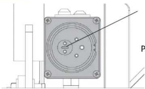
Technical diagram of a mechanical component with mounting holes and a central circular feature, labeled 'P' (no text or symbols beyond label)Phase inverter
Check the rotation direction of the motor if necessary please change direction by using the phase inverter. (phase inverter inside the plug - see picture on the left)
16.2 Operating
16.2.1 Splitting lever
Splitting force and splitting speed are controlled by the splitting lever. The splitting lever is simply raised or lowered for operation.

flowchart
graph TD
    A["User"] --> B["Mouse Icon"]
    C["User"] --> D["Rabbit Icon"]
    B --> E["Arrow Right"]
    D --> F["Arrow Left"]
The first half stroke of the splitting lever is idle speed; press the splitting lever to the half stroke for maximum splitting force at slower speed to split the log at the beginning or particularly hard and seasoned logs.
Press the splitting lever to the end for faster speed at less splitting force to finish the splitting or to split usual logs.
16.2.2 Splitting

- Place the log vertically on the support table, so that it lies flat on its face. Press the left lever to lower the extended log fixing claw against the log to secure it. The extended log fixin claw can be adjusted to fit logs with different heights.
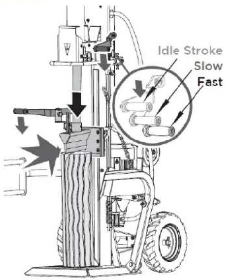

- Hold the left press lever. Meanwhile, move the splitter wedge down by pressing the right splitting lever to the half stroke to split the log slowly first and then press it to the end until the log is completely split.
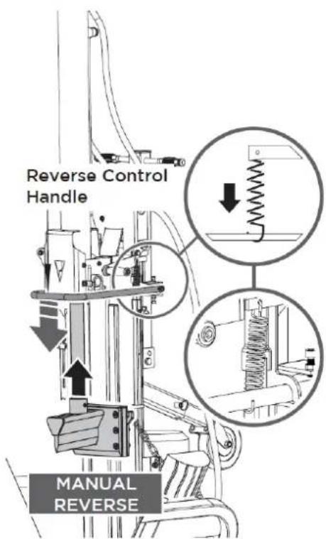

- Return the splitter wedge to the starting position. Operate the spring-loaded retract control lever to lift wedge above the height of log to be split.
16.2.3 Free a jammed log
Stack as you work. This will provide a safer work area, by keeping it uncluttered, and avoid the danger of tripping, or damaging the power cord.
17 MAINTENANCE

WARNING
Before carrying out any maintenance work, ensure that moving parts are stationary, that the machine is disconnected from the mains supply and / or that the PTO shaft is uncoupled.
17.1 Maintenance Schedule
| Activity | Model | |||
| ZI-HS16E | ZI-HS22EZ | ZI-HS30EZ | ZI-HS30Z | |
| Check oil level | After each oil change or every 8 oh* | After each oil change or every 8 oh | After each oil change or every 8 oh | After each oil change or every 8 oh |
| Change hydraulic oil | 1 x per year | 1 x per year | 1 x per year | 1 x per year |
| Change gear oil | after 25 oh, subsequently every six months or every 250 oh | after 25 oh, subsequently every six months or every 250 oh | after 25 oh, subsequently every six months or every 250 oh | |
*) oh ... operating hours
17.2 Replacing Oil
NOT ICE

Check the oil level regularly. Change the hydraulic oil completely at least once a year. Always dispose of used oil correctly and never throw it into household waste or sewage!
The hydraulic system of the log splitter is a closed system with oil tank, oil pump and control valve. The oil should be changed completely once a year.
The following hydraulic oils are recommended for the hydraulic transmission system of the log splitter:
- Shell Tellus 22
- Mobil DTE 11
• Aral Vitam GF 22 or
• BP Energol HLP-HM 2

If the oil level is too low, the oil pump can be damaged, whereas overfilling can lead to overheating of the hydraulic system. Therefore check the oil level regularly with the dipstick - see picture on the left!


Waste oils are toxic and must never be discharged into the environment. If necessary, contact your local authorities for information on proper disposal.
Change the hydraulic oil:
- Remove the oil drain plug to drain the oil from the hydraulic system.
- Use a drip pan to collect waste oil and particles.
- Inspect the oil for metal chips. (Metal chips in the oil are an indication of increased wear.)
• After the oil has been completely drained from the machine, reinstall the drain plug. - Top up the recommended fresh hydraulic oil via the oil filler plug.
• After changing the oil, actuate the wood splitter several times without actually splitting any wood. - Use a dipstick to check the oil level.
17.3 Sharpening Wedge
This log splitter is equipped with reinforced splitting wedge which blade is specially treated. After long periods of operation, and when required, sharpen the wedge using a fine toothed file removing any burrs or flat spots on the edge.
17.4 Gearbox Lubrication- for models ZI-HS22EZ and ZI-HS30(E)Z only
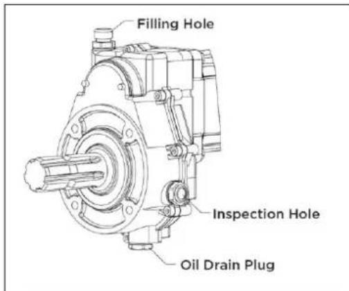
The gearbox is pre-serviced using SAE90 gear oil.
- Drain the gear oil after first 25 hours of use and refill with fresh oil as specified.
- Then change after every 250 hours of use or every six months, whichever is earlier.
• After each oil change check that the correct amount of oil has been poured into the gearbox. - Check oil level every 8 hours: Oil level is correct if the lower edge of the inspection hole is nearly covered with oil.
18 DISPOSAL
 | Observe the national waste disposal regulations. Do not dispose of the machine, machine components or equipment in residual waste. If necessary, contact your local authorities for information on the disposal options available. If you buy a new machine or an equivalent device from your specialist dealer, he is obliged in certain countries to dispose of your old machine properly. |
 | Altöle sind giftig und dürfen nicht in die Umwelt gelangen. Kontaktieren Sie gegebenenfalls Ihre lokalen Behörden für Informationen bezüglich der ordnungsgemäßen Entsorgung. |
19 TROUBLESHOOTING
| PROBLEM | PROBABLE CAUSE | REMEDY SUGGESTED |
| Motor does not start | Switch is OFFSelf-locking sleeve is disconnected (see chapters 14.2.1 and 14.2.2). | Set switch to ONConnect self-locking sleeve |
| Incorrect motor rotation direction | Incorrect connection | Reverse polarity (by an electrician) |
| Log Splitter does not work while motor running | Valve is not opened owing to the connection parts looseningControl Levers or connection parts bentLower hydraulic oil level | Check and tighten the partsRepair the bent partsCheck and refill hydraulic oil |
| Log Splitter works with abnormal vibration and noise | Lower hydraulic oil level | Check and refill hydraulic oil |

All repairs on this machine must be carried out by a specialist for this product!

20 PREFACIO (ES)
Estimado cliente,
natural_image
Technical line drawing of a mechanical pump assembly (no text or symbols)
natural_image
Technical line drawing of a vehicle suspension system with mechanical components and a magnified inset showing internal components (no text or labels)
natural_image
Technical line drawing of a mechanical component with mounting holes and a central circular feature (no text or symbols)flowchart
graph TD
    A["User"] --> B["Mouse Icon"]
    C["User"] --> D["Rabbit Icon"]


Cher client, chère cliente,
natural_image
Technical line drawing of a mechanical pump assembly (no text or symbols)
natural_image
Technical diagram of a mechanical component with mounting holes and a central circular feature, shown without any text or symbols.Inverseur de phase
flowchart
graph TD
    A["Mouse Icon"] --> B["Arrow"]
    C["Red Rabbit Icon"] --> D["Arrow"]

(EN) With original ZIPPER spare parts you use parts that are attuned to each other shorten the installation time and elongate your machines lifespan.
IMP OR TAN T
The installation of other than original spare parts voids the warranty!
So you always have to use original spare parts
When you place a spare parts order please use the service formular you can find in the last chapter of this manual. Always take a note of the machine type, spare parts number and partname. We recommend to copy the spare parts diagram and mark the spare part you need.
You find the order address in the preface of this operation manual.
Teile Liste / Parts List ZI-HS22EZ / ZI-HS30(E)Z
| No. | Description | Qty |
| 1 | Upper High Pressure Hose | 1 |
| 2 | Seal Kit 22 | 9 |
| 3 | Lower High Pressure Hose | 1 |
| 4 | Hose Link | 2 |
| 5 | Upper Guard | 1 |
| 6 | cylinder Lock Plate | 1 |
| 7 | Pin | 2 |
| 8 | Bolt M8X25 (65677,65682) | 6 |
| Bolt M8X35(65687,65692) | 6 | |
| 9 | Cylinder | 1 |
| 10 | Bolt M10x25 | 6 |
| 11 | Washer 10 | 3 |
| 12 | Sleeve 2 | 2 |
| 13 | Bolt | 2 |
| 14 | Shaft | 1 |
| 15 | Grip | 2 |
| 16 | Sleeve | 2 |
| 17 | Flat Washer 12 | 2 |
| 18 | Cylinder pin | 2 |
| 20 | Flat Washer 6 | 6 |
| 21 | Flange Nut M12 | 10 |
| 22 | Right Plate | 1 |
| 23 | Friction Plate | 4 |
| 24 | Control U-Handle | 1 |
| 25 | Left Plate | 1 |
| 26 | Baffle Plate | 2 |
| 27 | Wedge Weldment | 1 |
| 28 | Pin 12X70 | 1 |
| 29 | Screw M12X70 | 6 |
| 30 | Retaining hook | 1 |
| 31 | Grip | 1 |
| 32 | Guard Bracket Left | 1 |
| 33 | Locknut M10 | 4 |
| 34 | Locknut M12 | 2 |
| 35 | Locating Sleeve | 1 |
| 36 | Hoist Guard | 1 |
| No. | Description | Qty |
| 37 | Bolt M10X35 | 4 |
| 38 | Nut M14 | 1 |
| 39 | Screw M6X10 | 1 |
| 40 | Screw | 1 |
| 41 | Pin | 2 |
| 42 | Locating Plate | 1 |
| 43 | Reset torsion Spring | 1 |
| 44 | Washer 14 | 1 |
| 45 | Big Washer 12 | 1 |
| 46 | Bolt M6x100 | 1 |
| 47 | Nut M16 | 1 |
| 48 | Oil Dipstick | 1 |
| 49 | Hose Connector | 1 |
| 50 | Sealing Kit 20 | 5 |
| 51 | Valve | 1 |
| 52 | Screw M6X15 | 2 |
| 53 | High Pressure Hose 2 D12 | 1 |
| 54 | Nipple M20x1.5-M22x1.5 | 1 |
| 55 | Bolt M8X65 | 2 |
| 56 | Nut M8 | 8 |
| 57 | Oil Return Hose | 1 |
| 58 | Hose Clamp | 6 |
| 59 | Pin 3 | 2 |
| 60 | Round Plate | 1 |
| 61 | Valve Connecting Plate | 2 |
| 62 | Limit Plate | 1 |
| 63 | Bolt M12x45 | 4 |
| 64 | Big Washer 10 | 2 |
| 65 | Nut M10 | 13 |
| 66 | Pressing Plate | 1 |
| 67 | Adjusting Plate | 1 |
| 68 | Pull Rod | 1 |
| 69 | Nut M4 | 4 |
| 70 | Screw M8X25 | 4 |
| 71 | Nut M8 | 4 |
| 72 | Pin 6x45 | 1 |
| 73 | Switch | 1 |
Parts with grey background are not in use for ZI-HS30Z!
Parts with grey background are not in use for ZI-HS30Z!
Company ZIPPER Maschinen GmbH grants for mechanical and electrical components a warranty period of 2 years for amateur use; and warranty period of 1 year for professional use, starting with the purchase of the final consumer. In case of defects during this period, which are not excluded by paragraph 3, ZIPPER will repair or replace the machine at its own discretion.
2.) Report:
In order to check the legitimacy of warranty claims, the final consumer must contact his dealer. The dealer has to report in written form the occurred defect to ZIPPER. If the warranty claim is legitimate, ZIPPER will pick up the defective machine from the dealer. Returned shippings by dealers which have not been coordinated with ZIPPER, will not be accepted and refused.
3.) Regulations:
a) Warranty claims will only be accepted, when a copy of the original invoice or cash voucher from the trading partner of ZIPPER is enclosed to the machine. The warranty claim expires if the accessories belonging to the machine are missing.
b) The warranty does not include free checking, maintenance, inspection or service works on the machine. Defects due to incorrect usage of the final consumer or his dealer will not be accepted as warranty claims either. Some examples: usage of wrong fuel, frost damages in water tanks, leaving fuel in the tank during the winter, etc.
c) Defects on wear parts are excluded, e.g. carbon brushes, collection bags, knives, cylinders, cutting blades, clutches, sealings, wheels, saw blades, splitting crosses, riving knives, riving knife extensions, hydraulic oils, oil/air/fuel filters, chains, spark plugs, sliding blocks, etc.
d) Also excluded are damages on the machine caused by incorrect or inappropriate usage, if it was used for a purpose which the machine is not supposed to, ignoring the user manual, force majeure, repairs or technical manipulations by not authorized workshops or by the customer himself, usage of non-original ZIPPER spare parts or accessories.
e) After inspection by our qualified personnel, resulted costs (like freight charges) and expenses for not legitimated warranty claims will be charged to the final customer or dealer.
f) In case of defective machines outside the warranty period, we will only repair after advance payment or dealer's invoice according to the cost estimate (incl. freight costs) of ZIPPER.
g) Warranty claims can only be granted for customers of an authorized ZIPPER dealer who directly purchased the machine from ZIPPER. These claims are not transferable in case of multiple sales of the machine.
4.) Claims for compensation and other liabilities:
The liability of company ZIPPER is limited to the value of goods in all cases. Claims for compensation because of poor performance, lacks, damages or loss of earnings due to defects during the warranty period will not be accepted. ZIPPER insists on its right to subsequent improvement of the machine.
42 GARANTÍA Y SERVICIO (ES)
1.) Garantía:
We monitor the quality of our delivered products in the frame of a Quality Management policy.
Your opinion is essential for further product development and product choice. Please let us know about your:
- Impressions and suggestions for improvement.
- experiences that may be useful for other users and for product design
- Experiences with malfunctions that occur in specific operation modes
We would like to ask you to note down your experiences and observations and send them to us via FAX, E-Mail or by post
Please describe amongst others in the problem: What has cause the problem/defect, what was the last activity before you noticed the problem/defect? For electrical problems: Have you had checked you electric supply and the machine already by a certified electrician?
3. Bitte beachten
/ Additional information
INCOMPLETELY FILLED SERVICE FORMS CANNOT BE PROCESSED! FOR GUARANTEE CLAIMS PLEASE ADD A COPY OF YOUR ORIGINAL SALES / DELIVERY RECEIPT OTHERWISE IT CANNOT BE ACCEPTED. FOR SPARE PART ORDERS PLEASE ADD TO THIS SERVICE FORM A COPY OF THE RESPECTIVE EXPLODED DRAWING WITH THE REQUIRED SPARE PARTS BEING MARKED CLEARLY AND UNMISTAKABLE. THIS HELPS US TO IDENTIFY THE REQUIRED SPARE PARTS FASTLY AND ACCEL- LERATES THE HANDLING OF YOUR INQUIRY.


- MAINTENANCE 44
- DISPOSAL 46
- TROUBLESHOOTING 46
- SEGURIDAD 48
- VORWORT (DE)
- Phasenwender
- Observe the safety instructions!
- Copyright
- Customer support:
- ZIPPER-MASCHINEN assumes no responsibility or warranty for any other use or use beyond this and for any resulting damage to property or injuries.
- Operating conditions:
- Unauthorised use:
- Safety instructions
- Residual risks
- DANGER
- WARNING
- CAUTION
- NOTICE
- ASSEMBLY
- ZI-HS16E
- Coupling the PTO shaft
- Uncoupling the PTO shaft
- TRANSPORT
- ZI-HS16E
- OPERATION
- Preparatory activities
- Greasing the splitting wedge
- Bleeding the hydraulic system
- Checking the rotation direction of the motor - for models ZI-HS16E, ZI-HS22EZ and ZI-HS30EZ only
- NOT ICE
- Operating
- Splitting lever
- Free a jammed log
- MAINTENANCE
- Maintenance Schedule
- Replacing Oil
- Change the hydraulic oil:
- Sharpening Wedge
- Gearbox Lubrication- for models ZI-HS22EZ and ZI-HS30(E)Z only
- DISPOSAL
- TROUBLESHOOTING
- PREFACIO (ES)
- Estimado cliente,
- Cher client, chère cliente,
- IMP OR TAN T
- The installation of other than original spare parts voids the warranty!
- 2.) Report:
- 3.) Regulations:
- 4.) Claims for compensation and other liabilities:
- GARANTÍA Y SERVICIO (ES)
- 1.) Garantía:
- Bitte beachten
- / Additional information
Brand : Zipper
Model : ZIHS22EZ
Category : Splitter