
ZIHS10TN - Splitter Zipper - Free user manual and instructions
Find the device manual for free ZIHS10TN Zipper in PDF.

| Product type | Log splitter (wood splitter) |
| Brand | Zipper |
| Model | ZIHS10TN |
| Power supply | Electric motor 230 V / 50 Hz (single-phase) |
| Main functions | Vertical splitting of firewood along the grain, with hydraulic system |
| Safety | Protection arm, safety hook, fixing claw, on/off switch, residual current device (RCD) 0.03 A |
| Maintenance | Lubricate pistons before use, bleed hydraulic circuit, annual hydraulic oil change, sharpen splitting wedge if necessary |
| Spare parts | Use only original Zipper spare parts |
| Repairability | Any repair must be carried out by a product specialist |
| Warranty | 2 years for non-commercial use, 1 year for commercial use |
Frequently Asked Questions - ZIHS10TN Zipper
User questions about ZIHS10TN Zipper
0 question about this device. Answer the ones you know or ask your own.
Ask a new question about this device
Download the instructions for your Splitter in PDF format for free! Find your manual ZIHS10TN - Zipper and take your electronic device back in hand. On this page are published all the documents necessary for the use of your device. ZIHS10TN by Zipper.
USER MANUAL ZIHS10TN Zipper
natural_image
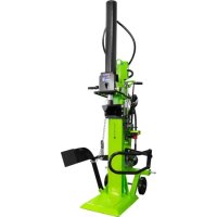
Green industrial machine labeled 'ZIPPER-MATHN' with mechanical arms and control panel (no readable text beyond label)ZI-HS10TN
EAN: 9120039233765

natural_image
Green industrial machine with black components and a handle, no visible text or symbols
natural_image
Green industrial machine with mechanical arms and control components (no visible text or symbols)ZI-HS12TN
EAN: 9120039233772
ZI-HS14TN
EAN: 9120039233789
13.1 Safety instructions.... 25
13.2 Residual risks 26
14 ASSEMBLY 27
15 TRANSPORT 29
16 OPERATION 29
16.1 Preparatory activities 29
16.1.1 Greasing the ram surface 29
16.1.2 Bleeding the hydraulic system 30
16.1.3 Checking the rotation direction of the motor - for models ZI-HS12TN and ZI-HS14TN only 30
16.2 Operating 30
16.2.1 Splitting lever 30
16.2.2 Splitting 31
16.2.3 Free a jammed log 31
17 MAINTENANCE 32
17.1 Maintenance Schedule 32
17.2 Replacing Oil.... 32
17.3 Sharpening Wedge.... 33
18 DISPOSAL 33
19 TROUBLESHOOTING 33
20 UVOD (SL) 34
21 VARNOST 35
EN CE-Conformal! - This product complies with the EC-directives.
READ THE MANUAL! Read these operating instructions carefully and familiarize yourself well with the operating elements of your machine in order to be able to operate and maintain it properly and thus prevent damage to man and machine.
EN Keep your workspace tidy! Untidiness may result in accidents.
EN Do not remove or tamper with any protection or safety devices.
EN Dispose used oil in an environmental-friendly way!
EN Do not use in the rain!
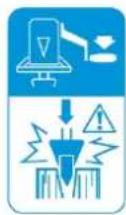
EN Danger! Keep clear of moving parts!
EN Do not remove jammed logs by hands!
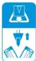
EN Before starting any repair, maintenance or cleaning always disconnect device from the mains!
EN Avoid injury from the movement of the splitting blade.
EN Keep children and bystanders away from the work area!
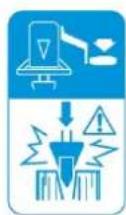
EN Do not split wood when machine is transporting
SL Med transportom cepilnika ne cepite lesa.
EN Do not split wood when machine is leaning
natural_image
Three blue circular icons showing a person wearing safety goggles, a hand gesture, and a boots (no text or symbols)EN Wear personal protective equipment!

| 1 | Holzspalter-Rahmen & Antriebseinheit / log splitter frame & power unit / Ogrodje cepilnika lesa in pogonska enota / Rám štiepača & hnacia jednotka / hasítókeret és meghajtóegység / Marco y propulsión de la rajadora de leňa / Cadre fendeur de bois et unité d'entraînement / Okvir stroja za cijepanje drva i pogonska jedinica |
| 2 | Schutzarm / guard arm / Zaščitni ročaj / Ochranné rameno / védőkar / Brazo de protección / Bras de protection / Zaštitna ruka |
| 3 | Stammheber / log lift / Dvižnik za hlod / Zdvihák polien / rönkmozgató / Levantador de troncos / Dispositif pour soulever des grumes / Podizač debla |
| 4 | Rückhalte-Haken / retaining hook / Zadrževalni kavelj / Pridržiavací hák / tartóhorog / Gancho de retención / Crochet de retenue / Kuka za držanje |
| 5 | Räder / wheels / Kolesa / Transportné kolesá / kerekek / Ruedas / Roues / Kotači |
| 6 | Radachse / wheel shaft / Kolesna os / Os kolesa / keréktengely / Eje de rueda / Axe de roue / Osovina kotača |
| 7 | Stützrad / support wheel / Podporno kolo / Oporné koleso / tartókerék / Rueda de apoyo / Roue de support / Potporni kotač |
| 8 | Bedienungsanleitung / operator's manual / Navodilo za delo s strojem / Návod na obsluhu / használati utasítás / Instrucciones de uso / Mode d'emploi / Uputa za uporabu |
| 9 | Beutel mit Kleinteilen, inklusive / hardware bag including / Vrečka z drobnimi deli / Vrecko s drobnými dielmi, vrátane:/ táska szerszámokkal / Bolsa con piezas pequeñas, incluida / Sachet de petites pièces, inclus / Vrećica sa sitnim dijelovima, uklj.: |
3.1 Technische Daten / Technical Data/ Tehnični podatki / Technické údaje / Technikai adatok / Datos técnicos / Données techniques / Tehnički podaci
| ZI-HS10TN | ZI-HS12TN | ZI-HS14TN | |
| Motorleistung /motor power /Moč motorja / Výkon motora/Motor teljesítmény / Potencia del motor/Puissance du moteur / Snaga motora | 3000WS6 (40%) IP54 | 3300WS6 (40%) | 3500WS6 (40%) |
| Spannung / voltage /Napetost / Napätie FeszültségTensión / Tension / Napon | 230 V (~1p) /50 Hz | 400 V (~3p)/ 50 Hz | 400 V (~3p)/ 50 Hz |
| Schutzklasse / Protection class /Zaščitni razred / Ochranná trieda/Védelmi osztály / Clase de protección / Classe deprotection / Klasa zaštite | IP54 IP54 | IP54 | |
| Spaltgut-Durchmesser / log size capacityPremer cepljenca / Priemer poleneRönk átmérő: ∅ / Diámetro del material para rajar /Diamètre du bois à fender / Promjer materijala: ∅ | 10-30 cm | 10-30 cm | 10-30 cm |
| Spaltgut-Länge / log size capacityDolžina cepljenca / Dížka poleneRönk hosszúság / Longitud del material para rajar /Longueur du bois à fendre / Dužina materijala | 56-104 cm | 56-104 cm | 56-104 cm |
| Maximale Spaltkraft / maximum forceMaksimalna moč cepljenja / Max. štiepacia silaMax eróhatás / Fuerza máxima de rajado / Puissancede fendage maximale / Maksimalna sila cijepanja | 11 t ± 10% | 12 t ± 10% | 14 t ± 10% |
| Hydraulikdruck / hydraulic pressureHidravlični tlak / Hydraulický tlakHidraulikus nyomás / Presión hidráulica / Pressionhydraulique / Hidraulički tlak | 25,2 MPa 24 | MPa 24,6 MPa | |
| Hydrauliköl-Kapazität / hydraulic oil capacityHidravlično olje - kapaciteta / Objem hydraul. olejaHidraulika olaj kapacitás / Capacidad de aceitehidráulico / Capacité d'huile hydraulique / Kapacitethidrauličkog ulja | 7 | 7 | 7,5 | | ||
| Verfahrweg Spaltkeil / ram travelHod cepilnega klina / Pojazd štiepacieho klinuHasítóék / Desplazamiento de la cuña de separación /Course du coin à refendre / Hod klina za cijepanje | 85 cm | 85 cm | 85 cm |
| Vorwärtsgeschwindigkeit / speed forwardPospeševalna hitrost / Rýchlost vpredSebesség előre / Velocidad de avance / Vitesse d'avance / Brzina unaprijed | 13,9 cm/s | 23,2 cm/s | 21,8 cm/s |
| Vor. Geschw. bei Lastspeed forward under loadPospeševalna hitrost pri obremenitviRýchlost vpred pri zátažiSebesség terhelés alattVeloc. avance con cargaVitesse d'avance en chargeBrzina unaprijed pod opterećenjem | 2,9 cm/s | 4,2 cm/s | 4,2 cm/s |
| Rückwärtsgeschwindigkeitspeed backwardVzvratna hitrostRýchlost vzadSebesség hátraVelocidad de retrocesoVitesse de reculBrzina unatrag | 3,7 cm/s | 5,2 cm/s | 5,2 cm/s |
| Lärmdruckpegel / sound pressure level /Nivo zvočnega tlaka / Hladina akustického tlakuZajszint / Nivel de presión sonora / Niveau de pressionacoustique / Razina zvučnog tlaka ( L_DA ) | ≤ 80 dB(A) | ≤ 80 dB(A) | ≤ 80 dB(A) |
| Vibrationspegel / VibrationNivo vibriranja / Hladina vibráciíRezgés / Nivel de vibración / Seuil de vibrationsRazina vibracija | < 2,5 m/s ^2 < 2,5 m/s ^2 < 2,5 m/s ^2 |
| Länge / length /Dolžina / DlžkaHosszúság / Longitud / Longueur / Duljina | 144 cm 144 cm 144 cm |
| Breite / width /Širina / ŠírkaSzélesség / Ancho / Largeur / Širina | 133 cm 133 cm 135 cm |
| Höhe / height /Višina / VýškaMagasság / Altura / Hauteur / Visina | 228 cm 228 cm 228 cm |
| Gewicht (Netto) / weight (net) /Teža (neto) / Hmotnosť (Netto)Súly (nettó) / Peso (neto) /Poids (net) / Težina (neto) | 173,4 kg 178,4 kg 184,9 kg |
| Gewicht (Brutto) / weight (gross)Teža (bruto) / Hmotnosť (Brutto)Súly (bruttó) / Peso (bruto)Poids (brute) / Težina (bruto) | 183,4 kg 188,4 kg 194,9 kg |
With the 3-phase 400 Volt / 50Hz motor, the log splitter should be connected to a standard 400 V ± 10% / 50 Hz ± 1% mains supply. The electrical supply must be equipped with protective devices against undervoltage, overvoltage, overcurrent and with a residual current protective device with a maximum rated residual current of 0.03 A. The mains connection cable must be connected to the mains supply.
Mains connection cable and extension cable must be 5-core = 3P + N + PE (3/N/PE). The mains connection must be fused with a maximum of 16 A. Rubber power cables must comply with EN60245 and be marked with the symbol "H 07 RN". The marking of the cables is required by law. With 230 Volt / 50Hz motor, the log splitter should be connected to standard 230V±10%/50Hz±1%. Electrical supply which has protection devices of under-voltage, over-voltage, over-current (16 A) as well as a residual current device (RCD) which maximum residual current rated at 0.03A. Electrical connection rubber cables must comply with EN60245 which are always marked with symbol H 07 RN. Cables should be identified, as it is a legal requirement.
natural_image
Technical line drawing of a mechanical device with directional arrows indicating motion (no text or symbols)natural_image
Technical line drawing of a mechanical device with wheels and a handle, no text or symbols presentnatural_image
Technical diagram of a mechanical component with concentric circles and mounting holes (no text or symbols)Inversor de
natural_image
Technical illustration of a forklift with a magnified inset showing a mechanical component (no text or symbols present)
This operating manual contains information and important notes on commissioning and handling the wood splitter models ZI-HS10TN; ZI-HS12TN and ZI-HS14TN.
In the following, the usual trade name of the device (see cover sheet) in this operating manual is replaced by the designation "machine".
The operating manual is part of the machine and must not be removed. Keep it for future reference and include this manual with the machine if it is passed on to third parties!
Observe the safety instructions!

Read these instructions carefully before use. This facilitates proper handling and prevents misunderstandings and possible damage. Follow the warnings and safety instructions. Failure to do so may result in serious injury.
Due to the constant further development of our products, illustrations and contents may differ slightly. If you find any errors, please inform us.
Subject to technical changes!
Copyright
© 2018
This documentation is protected by copyright. The thereby constitutional rights remain reserved – in particular, the reprint, translation and extraction of photos and illustrations will be prosecuted.
The place of jurisdiction is the regional court Linz or the court responsible for 4707 Schlüsslberg.
Customer support:
Only use the machine in a technically perfect condition and in accordance with its intended use, safety-conscious and aware of the dangers! Have faults which could impair safety rectified immediately!
The machine is intended exclusively for the following activities:
For splitting wood in the direction of the grain, with dimensions that are within the limits specified in the "Technical data" section.
The splitting process of the machine is intended for operation by only one person.
ZIPPER-MASCHINEN assumes no responsibility or warranty for any other use or use beyond this and for any resulting damage to property or injuries.
Operating conditions:
The machine is intended for use under the following conditions:
Humidity: max. 50 %
Temperature +5°C to +40°C
Altitude above sea up to 1.000 m level
Any improper use or disregard of the information and instructions given in this manual will invalidate all warranty claims and claims for damages against Zipper GmbH.
Unauthorised use:
• Operation of the machine without adequate physical and mental aptitude
- Operating the machine without knowledge of the operating instructions
• Changes in the design of the machine
- Operating the machine under explosive conditions
- Operating the machine outside the specified power range
- Remove the safety markings attached to the machine.
- Modify, circumvent or disable the safety devices of the machine.
13.1 Safety instructions
Warning signs and/or stickers on the machine which are illegible or have been removed must be replaced immediately!
Local laws and regulations can determine the minimum age of the operator and restrict the use of this machine!
In order to avoid malfunctions, damage and health impairments, the following measures for safe working must also be observed:
- Do not split soaked wood.
- Only split the wood upright in the direction of the grain!
- Do not split wood that contains foreign objects such as nails, cables, etc.
- Operate the machine only in well-ventilated rooms or outdoors.
- Never operate the machine outdoors when it is raining.
- Choose a level, vibration-free, non-slip surface as the installation location.
- Ensure sufficient lighting conditions at the workplace.
- Keep the working area free of obstacles (e.g. pieces of wood, leftover wood, etc.).
- Before each use, check the machine for its perfect condition (tight fit of hoses and screws, operability of the switch-off devices, etc.).
• Never leave the running machine unattended. - The machine may only be operated, serviced or repaired by persons who are familiar with it and who have been informed of the dangers arising during this work.
-
Although it is possible that several operators could work on the machine (e.g. for loading and unloading), only one person should ever operate the splitting process.
-
As the operator of the machine, make sure that unauthorised persons maintain an appropriate safety distance from the machine and, in particular, keep children away from the machine.
- Wear suitable work clothing (eye protection, work gloves, safety shoes and close-fitting work protective clothing, never loose clothing, ties, jewellery, etc. - danger of being drawn in!
- Keep your hands away from crevices and cracks that open in the trunk.
- Do not reach into the splitting area.
- Do not work on the machine if you are tired, not concentrated or under the influence of medication, alcohol or drugs!
- Keep the unit away from potential ignition sources such as pilot lights and/or open flames (danger of fire and explosion).
- Do not smoke in the immediate vicinity of the machine.
- Make sure that the on/off switch is in the "Off" position before switching on the machine.
• Make sure that the machine is earthed if necessary. - Only use suitable extension cords.
- Before cleaning, maintenance or repair work, always disconnect the device from the power or drive source and secure it against unintentional reconnection.
- Only use intact tools.
13.2 Residual risks
Despite proper use, certain residual risks remain. Due to the design and construction of the machine, hazardous situations may occur which are indicated as follows in these operating instructions:

DANGER
A safety instruction of this type indicates an imminently dangerous situation which, if not avoided, will result in death or serious injury.

WARNING
This type of safety information indicates a potentially hazardous situation which, if not avoided, could result in serious injury or even death.

CAUTION
This safety information indicates a potentially hazardous situation which, if not avoided, may result in minor or moderate injury.

NOTICE
Such a safety notice indicates a potentially hazardous situation which, if not avoided, may result in property damage.
Irrespective of all safety regulations, your common sense and corresponding technical suitability and/or training remain the most important safety factor for fault-free operation of the machine.
Safe working depends on you!
14 ASSEMBLY

A. Mounting the wheel axle and wheels: Slide the wheel axle into the two holes on the frame and attach the wheels to it. Secure the wheels with a cotter pin and attach wheel caps.
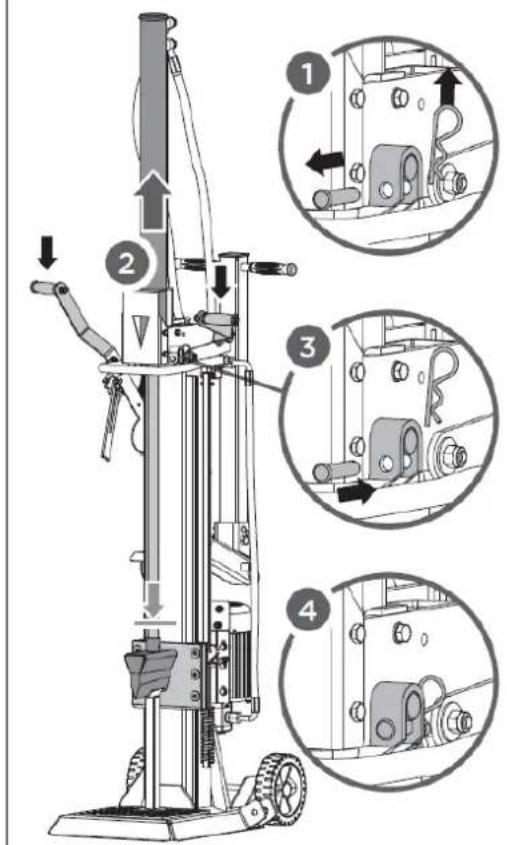
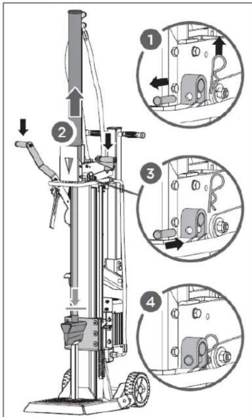
B. Expanding the wedge ram: Remove the R-pins (1). Keeping the support stand against the wedge, lower both control handles to expand wedge ram (2). Insert the R-pins to secure the cylinder to the splitter (3). Secure the R pins with the cotter pin into the spring tabs (4).

NOTICE
For this process, it is necessary to have the log splitter ready for operation. Hydraulic oil filled, motor connected to main supply.
natural_image
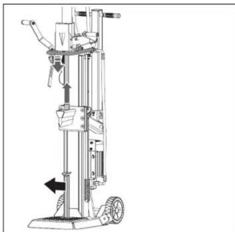
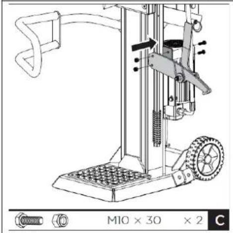
Technical line drawing of a mechanical device with directional arrows indicating motion (no text or symbols)C. Removing the support stand: Release both control handles to retract the wedge ram. Remove the support stand.
natural_image
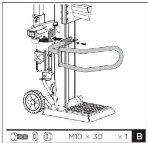
Technical line drawing of a mechanical device with wheels and a handle, no text or symbols presentD. Mounting the guard arm: Align the hole and locking pin of the guard arm with the mount bracket. Secure the guard arm with a M10 × 30 hex bolts, two washers and a nut from the hardware bag.
E. Mounting the retaining hook: Position the retaining hook onto the frame and secure with two M10×30 hex bolts and nuts.

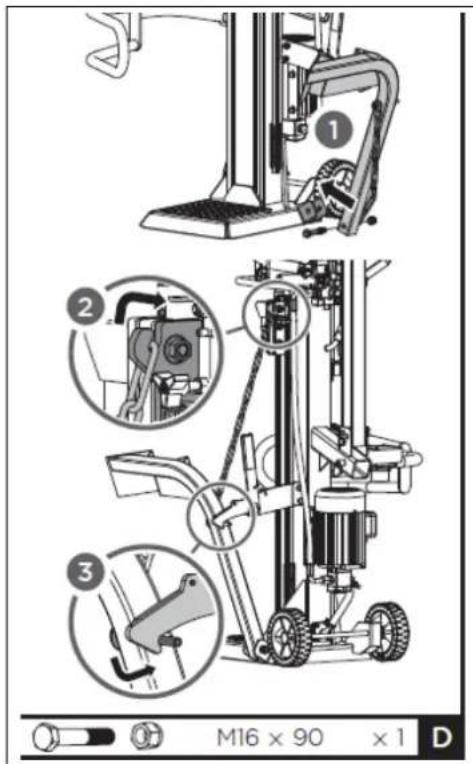
F. Mounting the log lift: Position the log lift inside the mounting bracket and align with mounting bracket holes. Secure with a M16×90 hex bolt and nut. Hook the lift chain to wedge slide guide.
15 TRANSPORT
For easier transport, the log splitter has two wheels, a support wheel and a transport handle.
WARNING
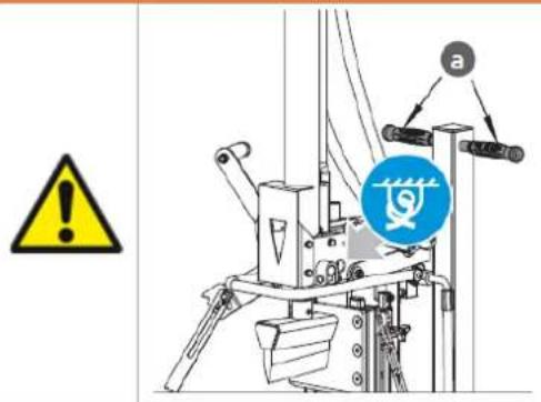
- If a crane is used, tie the rope at the lifting point belwo the blue bundling label, then hoist the machine with the crane see illustration on the left.
- Never attach the crane hook to the transport handle (a)!
- Before moving the log splitter, make sure that the cover on the oil tank is firmly closed!
- To move the splitter, grasp the handle (a) and carefully tilt machine backwards!
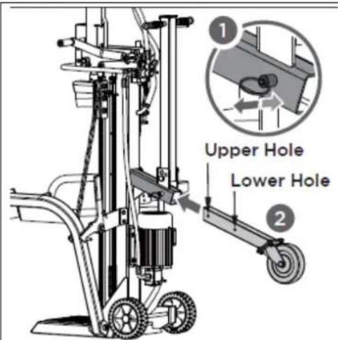
A. Moving support wheel to the transport position: To mount the support wheel, remove the spring bolt and push the square tube with the support wheel into the holder (1). Then select the upper hole for transport and fix the square tube in that position using the spring bolt (2).

CAUTION
The upper hole is for transport and the lower hole is for storage only.
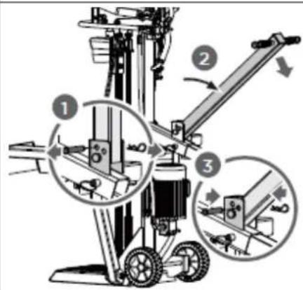
B. Fold out the transport handle: The transport handle is normally fixed in an upright position. To transport the log splitter, the transport handle must be folded out as shown in the illustration on the left. To unfold, release the pin (1), unfold the transport handle (2) and fix it in the unfolded position using the pin (3).
16 OPERATION
16.1 Preparatory activities
16.1.1 Greasing the ram surface
Apply a thin layer of grease to the surface of the ram of your log splitter before starting work. This will prolong the life of the tool.
16.1.2 Bleeding the hydraulic system
NOTICE

Never forget to loosen the oil tank cap! Otherwise the air in the system will be compressed and released again and again, which will destroy the seals of the hydraulic circuit and make the log splitter unusable.

Vent the hydraulic system before starting the log splitter. To do this, loosen the cover of the hydraulic oil tank by a few turns until the air can flow in and out gently.
The air flow through the oil tank should be visible during operation.
To prevent oil from leaking out, the oil tank cover must be tightly closed before each transport!
16.1.3 Checking the rotation direction of the motor - for models ZI-HS12TN and ZI-HS14TN only
NOTICE

Never run the motor in the wrong rotation direction. This will damage the pump and void the warranty.

natural_image
Technical line drawing of a mechanical component with mounting holes and a diagonal line (no text or symbols)Phase inverter
Check the rotation direction of the motor. If necessary reverse the polarity of the motor using a screwdriver (phase inverter inside the plug - see picture on the left).
16.2 Operating
16.2.1 Splitting lever
Splitting force and splitting speed are controlled by the splitting lever. The splitting lever is simply raised or lowered for operation.

flowchart
graph TD
    A["Start"] --> B["Mouse Icon"]
    C["Start"] --> D["Rabbit Icon"]
The first half stroke of the splitting lever is idle speed; press the splitting lever to the half stroke for maximum splitting force at slower speed to split the log at the beginning or particularly hard and seasoned logs.
Press the splitting lever to the end for faster speed at less splitting force to finish the splitting or to split usual logs.
16.2.2 Splitting

natural_image
Diagram of a mechanical lifting device with a magnified inset showing internal components (no text or symbols)
- Place the log vertically on the support table, so that it lies flat on its face. Press the left lever to lower the extended log fixing claw against the log to secure it. The extended log fixing claw can be adjusted to fit logs with different heights.
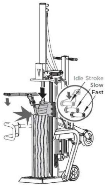
- Hold the left press lever. Meanwhile, move the splitter wedge down by pressing the right splitting lever to the half stroke to split the log slowly first and then press it to the end until the log is completely split.

- Return the splitter wedge to the starting position. Operate the spring-loaded retract control lever to lift wedge above the height of log to be split.
16.2.3 Free a jammed log
Stack as you work. This will provide a safer work area, by keeping it uncluttered, and avoid the danger of tripping, or damaging the power cord.
17 MAINTENANCE

WARNING
Before carrying out any maintenance work, ensure that moving parts are stationary, that the machine is disconnected from the mains supply.
17.1 Maintenance Schedule
| Activity | |
| Check oil level | After each oil change or every 8 operating hours |
| Change hydraulic oil | 1 x per year |
17.2 Replacing Oil
NOTICE

Check the oil level regularly. Change the hydraulic oil completely at least once a year. Always dispose of used oil correctly and never throw it into household waste or sewage!
The hydraulic system of the log splitter is a closed system with oil tank, oil pump and control valve. The oil should be changed completely once a year.
The following hydraulic oils are recommended for the hydraulic transmission system of the log splitter:
- Shell Tellus 22
- Mobil DTE 11
- Aral Vitam GF 22 or
• BP Energol HLP-HM 2

flowchart
graph TD
    A["Max."] --> B["Vertical Output"]
    C["Min."] --> B
    B --> D["Oil level"]
If the oil level is too low, the oil pump can be damaged, whereas overfilling can lead to overheating of the hydraulic system. Therefore check the oil level regularly with the dipstick - see picture on the left!


Waste oils are toxic and must never be discharged into the environment. If necessary, contact your local authorities for information on proper disposal.
Change the hydraulic oil:
- Remove the oil drain plug to drain the oil from the hydraulic system.
- Use a drip pan to collect waste oil and particles.
- Inspect the oil for metal chips. (Metal chips in the oil are an indication of increased wear.)
- After the oil has been completely drained from the machine, reinstall the drain plug.
- Top up the recommended fresh hydraulic oil via the oil filler plug.
- Apply a sealant to the oil filler plug and close it again.
- After changing the oil, actuate the wood splitter several times without actually splitting any wood.
- Use a dipstick to check the oil level.
17.3 Sharpening Wedge
This log splitter is equipped with reinforced splitting wedge which blade is specially treated. After long periods of operation, and when required, sharpen the wedge using a fine toothed file removing any burrs or flat spots on the edge.
18 DISPOSAL
 | Observe the national waste disposal regulations. Do not dispose of the machine, machine components or equipment in residual waste. If necessary, contact your local authorities for information on the disposal options available. If you buy a new machine or an equivalent device from your specialist dealer, he is obliged in certain countries to dispose of your old machine properly. |
 | Altöle sind giftig und dürfen nicht in die Umwelt gelangen. Kontaktieren Sie gegebenenfalls Ihre lokalen Behörden für Informationen bezüglich der ordnungsgemäßen Entsorgung. |
19 TROUBLESHOOTING
| PROBLEM | PROBABLE CAUSE | REMEDY SUGGESTED |
| Motor does not start | Switch is OFF | Set switch to ON |
| Incorrect motor rotation direction | Incorrect connection | Reverse polarity (by an electrician) |
| Log Splitter does not work while motor running | Valve is not opened owing to the connection parts looseningControl Levers or connection parts bentLower hydraulic oil level | Check and tighten the partsRepair the bent partsCheck and refill hydraulic oil |
| Log Splitter works with abnormal vibration and noise | Lower hydraulic oil level | Check and refill hydraulic oil |

All repairs on this machine must be carried out by a specialist for this product!

20 UVOD (SL)
Spoštovani kupec!
flowchart
graph TD
    A["Step 1: Paper"] --> B["Arrow pointing down"]
    B --> C["Step 2: Elephant"]
    C --> D["Arrow pointing up"]
    D --> E["Step 3: Rabbit"]
natural_image
Technical illustration of a mechanical lifting device with a magnified inset showing internal components (no text or symbols)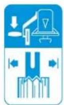
G. Vysunutie válca: Odstráňte skrutku (1). Držte opierku proti klinu a spustite obidve ovládacie rukoväte, aby ste zdvihli valec (2). Vložte skrutky na zaistenie valca ku štiepačke (3). Zaistite skrutky opat' pomocou závlačky v pružinovom výhybkovom jazyku (4).

POKYN
natural_image
Technical line drawing of a mechanical device with directional arrows indicating motion (no text or symbols)natural_image
Technical line drawing of a mechanical device with wheels and a handle, no text or symbols presentI. Montáž zaistovacieho háku: Nasadte zaistovacie hák na rám a zaistite ho dvoma šesthrannými skrutkami M10x30 a maticami.

natural_image
Technical line drawing of a square electronic component with mounting holes and a diagonal line indicating measurement or alignment (no text or symbols)fázový invertor
flowchart
graph TD
    A["Mouse Icon"] --> B["Arrow"]
    C["Mouse Icon"] --> D["Arrow"]
natural_image
Technical illustration of a forklift with a magnified inset showing the handle mechanism (no text or symbols present)
natural_image
Technical line drawing of a mechanical device with directional arrows indicating motion (no text or symbols)natural_image
Technical line drawing of a mechanical device with wheels and a handle, no text or symbols presentnatural_image
Technical line drawing of a mechanical component with concentric circles and mounting holes (no text or symbols)Fázisváltó
flowchart
graph TD
    A["Mouse Icon"] --> B["Arrow"]
    C["Red Rabbit Icon"] --> D["Arrow"]
natural_image
Diagram of a forklift with a close-up inset showing a mechanical component (no text or symbols present)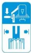
natural_image
Technical line drawing of a mechanical device with directional arrows indicating motion (no text or symbols)natural_image
Technical diagram of a mechanical component with concentric circles and mounting holes (no text or symbols)Inversor de fase
flowchart
graph TD
    A["Feeding Mouse"] --> B["Mouse"]
    C["Feeding Rabbit"] --> D["Rabbit"]
natural_image
Technical illustration of a forklift with a magnified inset showing a mechanical component (no text or symbols present)
Cher client, chère cliente,
natural_image
Technical line drawing of a mechanical device with directional arrows indicating motion (no text or symbols)natural_image
Technical line drawing of a mechanical device with wheels and a handle, no text or symbols presentflowchart
graph TD
    A["Animal Icon"] --> B["Arrow to Animal"]
    C["Animal Icon"] --> D["Arrow to Rabbit"]
natural_image
Technical illustration of a forklift with a magnified inset showing a mechanical component (no text or symbols present)
K. Montaža osovine kotača i kotača:
Osovinu kotača gurnite u dva otvora na okviru i na nju pričvrstite kotače. Kotače osigurajte rascjepkom i montirajte poklopac kotača.
L. Podizanje cilindra: Uklonite svornjak (1). Potporanj držite protiv klina i spustite obje upravljačke ručice kako biste podigli cilindar (2). Umetnite svornjake kako biste cilindar pričvrstili na stroj za cijepanje drva (3). Svornjake opet osigurajte zatikom u opružnim jezičcima (4).

NAPOMENA
natural_image
Technical line drawing of a mechanical device with wheels and directional arrows (no text or symbols)N. Montaža sigurnosne kuke: stavite sigurnosnu kuku na okvir i pričvrstite ju dvama vijcima M10x30 i maticama.
O. Pričvršćivanje podizača debla: postavite podizač debla unutar držača i poravnajte otvore s otvorima držača. Pričvrstite podizač debla vijkom M16x90 i maticom (1). Objesite lanac za dizanje u vodilicu klina i u sigurnosnu kuku (2, 3).
63 TRANSPORT
F. Otklapanje transportne drške: transportna drška u normalnom je slučaju fiksirana u uspravnom položaju. Za transport stroja za cijepanje drva transportnu dršku treba otklopiti kao što je prikazano na slici lijevo. Za otklapanje oslobodite utični zatik (1), otklopite transportnu dršku (2) i u otklopljenom položaju fiksirajte pomoću utičnog zatika (3).
64 RAD
64.1 Pripremne aktivnosti
64.1.1 Podmazivanje klipa
natural_image
Technical diagram of a mechanical component with concentric circles and mounting holes, no visible text or symbolsFazna
flowchart
graph TD
    A["Mouse Icon"] --> B["Arrow"]
    C["Red Rabbit Icon"] --> D["Arrow"]
natural_image
Technical illustration of a mechanical lifting device with an inset showing a close-up view of a component (no text or symbols present)
- Materijal koji cijepate postavite uspravno na st o l t a k o d a "n a Aktivirajte lijevu ručicu kako biste kandžu za fiksiranje debla spustili na deblo i osigurali ga. (Produžena kandža za fiksiranje debla može se prilaqoditi različitim visinama debla.)

(EN) With original ZIPPER spare parts you use parts that are attuned to each other shorten the installation time and elongate your machines lifespan.
IMPORTANT
The installation of other than original spare parts voids the warranty!
So you always have to use original spare parts
When you place a spare parts order please use the service formular you can find in the last chapter of this manual. Always take a note of the machine type, spare parts number and partname. We recommend to copy the spare parts diagram and mark the spare part you need.
You find the order address in the preface of this operation manual.
| No. | Description | Q'ty |
| 1 | Left Guard Bracket | 1 |
| 2 | Bolt M10x30 | 7 |
| 3 | Flat Washer 10 | 9 |
| 4 | Locating Pin Handle | 2 |
| 5 | Locknut M10 | 13 |
| 6 | Lift Chain 8 | 1 |
| 7 | Wedge Weldment | 1 |
| 8 | Bolt M12x65 | 6 |
| 9 | Friction Plate | 4 |
| 10 | Baffle Plate | 2 |
| 11 | Left Plate | 1 |
| 12 | Locknut M12 | 4 |
| 13 | Large Washer 12 | 3 |
| 14 | Cylindrical Pin 8x40 | 1 |
| 15 | Control U-Handle | 1 |
| 16 | Right Plate | 1 |
| 17 | Nut M12 | 6 |
| 18 | Axis Pin | 1 |
| 19 | Wheel Cap 12 | 2 |
| 20 | Lift Guard | 1 |
| 21 | Cylinder | 1 |
| 22 | Spring | 1 |
| 23 | Nut M8 | 5 |
| 24 | Bolt M8x30 | 2 |
| 25 | Bolt M8x80 | 1 |
| 26 | Oil Cap | 1 |
| 27 | O- Ring 25x2.65 | 1 |
| 28 | Oil Dipstick | 1 |
| 29 | Nylon Washer | 1 |
| 30 | Shaft | 1 |
| 31 | Extended Log Fixing Claw | 1 |
| 32 | Nut M8 | 3 |
| 33 | Log Fixing Claw | 1 |
| No. | Description | Q'ty |
| 34 | Locknut M8 | 4 |
| 35 | Large Washer 8 | 6 |
| 36 | Wing Bolt M8x25 | 1 |
| 37 | Bolt M8x20 | 3 |
| 38 | Lower Hose | 1 |
| 39 | Combined Washer 20 | 10 |
| 40 | Upper Hose | 1 |
| 41 | Valve Connector | 4 |
| 42 | Screw M12x120 | 2 |
| 43 | Operating Handle Grip | 2 |
| 44 | Thin Nut M12 | 2 |
| 45 | Lever | 1 |
| 46 | Reset Spring | 1 |
| 47 | Cylindrical Pin 8x60 | 1 |
| 48 | Bolt M8x12 | 4 |
| 49 | Front Support Plate for Cylinder | 1 |
| 50 | Bolt M8x25 | 2 |
| 51 | Rear Support Plate for Cylinder | 1 |
| 52 | Flat Washer 8 | 3 |
| 53 | Handle Grip | 1 |
| 54 | Square Plug | 1 |
| 55 | Pull Rod | 1 |
| 56 | Connecting Plate for Valve | 1 |
| 57 | Valve | 1 |
| 58 | Hose Nipple | 2 |
| 59 | Inlet Hose | 1 |
| 60 | Bolt M8x50 | 2 |
| 61 | Spring Washer 8 | 4 |
| 62 | Oil Hose 19 | 1 |
| 63 | Hose Clamp 28-36 | 2 |
| 64 | Hose Connector | 1 |
| 65 | Right Operating Lever | 1 |
| 66 | Large Washer 10 | 2 |
| No. | Description | Q'ty |
| 67 | Connectin Lever | 1 |
| 68 | Bolt M8x40 | 1 |
| 69 | Cylindrical Pin 6x40 | 2 |
| 70 | Stroke Adjusting Lever | 1 |
| 71 | Round Plate | 2 |
| 72 | Clip 2.5 | 1 |
| 73 | Large Washer 10 | 1 |
| 74 | Star Knob | 1 |
| 75 | Adjusting Sleeve | 1 |
| 76 | Screw M4x60 | 2 |
| 77 | Switch | 1 |
| 78 | Locknut M4 | 2 |
| 79 | Motor | 1 |
| 80 | Gear Pump | 1 |
| 81 | Screw M8x90 | 1 |
| 82 | Oil Hose 16 | 1 |
| 83 | Hose Clamp 20-26 | 2 |
| 84 | Wheel Cap | 2 |
| 85 | Wheel | 2 |
| 86 | Flat Washer 16 | 4 |
| 87 | Cotter Pin 2x20 | 2 |
| 88 | Wheel Axle | 1 |
| 89 | Locknut M16 | 2 |
| 90 | Bolt M16x90 | 2 |
| 91 | Screw Plug | 1 |
| 92 | Combined Washer 22 | 1 |
| No. | Description | Q'ty |
| 93 | Main Frame | 1 |
| 94 | Bolt M6x12 | 4 |
| 95 | Flat Washer 6 | 4 |
| 96 | Buffer Spring | 1 |
| 97 | O- Ring 50x2.65 | 1 |
| 98 | Oil Filter K | 1 |
| 99 | Bush K | 1 |
| 100 | Flange | 1 |
| 101 | Locating Plate | 1 |
| 102 | Hook | 1 |
| 103 | Rectangular Nozzle | 1 |
| 104 | Locknut M14 | 1 |
| 105 | Torsional Spring | 1 |
| 106 | Locating Bush for Spring | 1 |
| 107 | Locating Bush | 1 |
| 108 | Bolt M14x60 | 1 |
| 109 | Large Washer 14 | 2 |
| 110 | Screw M6x10 | 1 |
| 111 | Handle Grip | 1 |
| 112 | Support Wheel Assy. | 1 |
| 113 | Bolt M10x25 | 4 |
| 114 | Fixing Tube | 1 |
| 115 | Pin B: 16x85 | 1 |
| 116 | Clip 3 | 3 |
| 117 | Pin B: 12x50 | 2 |
| Pin B: 12x55 (Only for 65715) |
Company ZIPPER Maschinen GmbH grants for mechanical and electrical components a warranty period of 2 years for amateur use; and warranty period of 1 year for professional use, starting with the purchase of the final consumer. In case of defects during this period, which are not excluded by paragraph 3, ZIPPER will repair or replace the machine at its own discretion.
2.) Report:
In order to check the legitimacy of warranty claims, the final consumer must contact his dealer. The dealer has to report in written form the occurred defect to ZIPPER. If the warranty claim is legitimate, ZIPPER will pick up the defective machine from the dealer. Returned shippings by dealers which have not been coordinated with ZIPPER, will not be accepted and refused.
3.) Regulations:
a) Warranty claims will only be accepted, when a copy of the original invoice or cash voucher from the trading partner of ZIPPER is enclosed to the machine. The warranty claim expires if the accessories belonging to the machine are missing.
b) The warranty does not include free checking, maintenance, inspection or service works on the machine. Defects due to incorrect usage of the final consumer or his dealer will not be accepted as warranty claims either. Some examples: usage of wrong fuel, frost damages in water tanks, leaving fuel in the tank during the winter, etc.
c) Defects on wear parts are excluded, e.g. carbon brushes, collection bags, knives, cylinders, cutting blades, clutches, sealings, wheels, saw blades, splitting crosses, riving knives, riving knife extensions, hydraulic oils, oil/air/fuel filters, chains, spark plugs, sliding blocks, etc.
d) Also excluded are damages on the machine caused by incorrect or inappropriate usage, if it was used for a purpose which the machine is not supposed to, ignoring the user manual, force majeure, repairs or technical manipulations by not authorized workshops or by the customer himself, usage of non-original ZIPPER spare parts or accessories.
e) After inspection by our qualified personnel, resulted costs (like freight charges) and expenses for not legitimated warranty claims will be charged to the final customer or dealer.
f) In case of defective machines outside the warranty period, we will only repair after advance payment or dealer's invoice according to the cost estimate (incl. freight costs) of ZIPPER.
g) Warranty claims can only be granted for customers of an authorized ZIPPER dealer who directly purchased the machine from ZIPPER. These claims are not transferable in case of multiple sales of the machine.
4.) Claims for compensation and other liabilities:
The liability of company ZIPPER is limited to the value of goods in all cases. Claims for compensation because of poor performance, lacks, damages or loss of earnings due to defects during the warranty period will not be accepted. ZIPPER insists on its right to subsequent improvement of the machine.
75 GARANCIJA (SL)
1.) Garancija:
We monitor the quality of our delivered products in the frame of a Quality Management policy.
Your opinion is essential for further product development and product choice. Please let us know about your:
- Impressions and suggestions for improvement.
- experiences that may be useful for other users and for product design
- Experiences with malfunctions that occur in specific operation modes
We would like to ask you to note down your experiences and observations and send them to us via FAX, E-Mail or by post
Please describe amongst others in the problem: What has cause the problem/defect, what was the last activity before you noticed the problem/defect? For electrical problems: Have you had checked you electric supply and the machine already by a certified electrician?
3. Bitte beachten
/ Additional information
INCOMPLETELY FILLED SERVICE FORMS CANNOT BE PROCESSED! FOR GUARANTEE CLAIMS PLEASE ADD A COPY OF YOUR ORIGINAL SALES / DELIVERY RECEIPT OTHERWISE IT CANNOT BE ACCEPTED. FOR SPARE PART ORDERS PLEASE ADD TO THIS SERVICE FORM A COPY OF THE RESPECTIVE EXPLODED DRAWING WITH THE REQUIRED SPARE PARTS BEING MARKED CLEARLY AND UNMISTAKABLE. THIS HELPS US TO IDENTIFY THE REQUIRED SPARE PARTS FASTLY AND ACCEL- ERATES THE HANDLING OF YOUR INQUIRY.


- Observe the safety instructions!
- Copyright
- Customer support:
- ZIPPER-MASCHINEN assumes no responsibility or warranty for any other use or use beyond this and for any resulting damage to property or injuries.
- Operating conditions:
- Unauthorised use:
- Safety instructions
- Residual risks
- DANGER
- WARNING
- CAUTION
- NOTICE
- ASSEMBLY
- TRANSPORT
- OPERATION
- Preparatory activities
- Greasing the ram surface
- Bleeding the hydraulic system
- Checking the rotation direction of the motor - for models ZI-HS12TN and ZI-HS14TN only
- Phase inverter
- Operating
- Splitting lever
- Splitting
- Free a jammed log
- MAINTENANCE
- Maintenance Schedule
- Replacing Oil
- Change the hydraulic oil:
- Sharpening Wedge
- DISPOSAL
- TROUBLESHOOTING
- All repairs on this machine must be carried out by a specialist for this product!
- UVOD (SL)
- Spoštovani kupec!
- POKYN
- Cher client, chère cliente,
- Montaža osovine kotača i kotača:
- NAPOMENA
- TRANSPORT
- RAD
- Pripremne aktivnosti
- Podmazivanje klipa
- Fazna
- IMPORTANT
- 2.) Report:
- 3.) Regulations:
- 4.) Claims for compensation and other liabilities:
- GARANCIJA (SL)
- 1.) Garancija:
- Bitte beachten
- / Additional information
Brand : Zipper
Model : ZIHS10TN
Category : Splitter