
801 D4 - Speaker BOWERS & WILKINS - Free user manual and instructions
Find the device manual for free 801 D4 BOWERS & WILKINS in PDF.

| Brand | Bowers & Wilkins |
| Model | 801 D4 |
| Product Type | 3-way floorstanding speaker, bookshelf |
| Dimensions (H x W x D) | 1218 x 394 x 569 mm |
| Weight | Approximately 100 kg per speaker |
| Finish | Real wood veneer, lacquered |
| Number of ways | 3-way (Tweeter, Midrange, Bass) |
| Drivers | 1 x diamond dome tweeter, 1 x Continuum FST midrange, 2 x Aerofoil Cone bass |
| Nominal impedance | 8 ohms (minimum 3 ohms) |
| Sensitivity | 90 dB (1W/1m) |
| Frequency response | 18 Hz - 28 kHz +/- 3 dB |
| Recommended amplifier power | 50 W - 500 W |
| Connectivity | Bi-wiring, terminals accept 4mm banana plugs, 6/8 mm spade connectors, bare wire 4 mm |
| Included accessories | 2 midrange grilles, 4 bass grilles, link cables, stabilizers, caps, T45 tool, adjustment rod, cloth |
| Stabilization type | Adjustable spikes + anti-theft stabilizers |
| Tweeter decoupling | Yes, mechanical (decoupled housing) |
| Removable grilles | Yes, magnetic attachment |
| Care and cleaning | Dust with provided cloth, avoid abrasive products, for leather clean with lukewarm water |
| Safety | Very sharp spikes, do not touch. Wait for components to cool before intervention. |
| Spare parts and repairability | Contact customer service with product number (FP) and serial number (under rear midrange cover) |
| General information | Complies with RoHS, REACH, WEEE. Break-in time: approximately 15 hours of normal use. |
Frequently Asked Questions - 801 D4 BOWERS & WILKINS
User questions about 801 D4 BOWERS & WILKINS
0 question about this device. Answer the ones you know or ask your own.
Ask a new question about this device
Download the instructions for your Speaker in PDF format for free! Find your manual 801 D4 - BOWERS & WILKINS and take your electronic device back in hand. On this page are published all the documents necessary for the use of your device. 801 D4 by BOWERS & WILKINS.
USER MANUAL 801 D4 BOWERS & WILKINS
Welcome and thank you for choosing
Bowers & Wilkins. Our founder, John Bowers, believed that imaginative design, innovative engineering and advanced technology were keys that could unlock the enjoyment of audio in the home. His belief is one that we continue to share and inspires every product we design.
The 800 Series Diamond is the world's most advanced range of loudspeakers. Each model benefits from thoughtful installation, so we would suggest that you take some time to read this manual before you begin the installation process. Continue to page 4 →
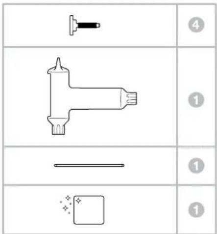
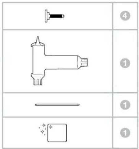
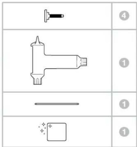
Carton Contents
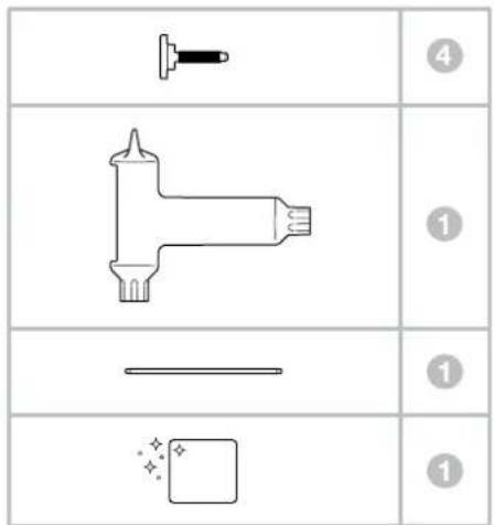
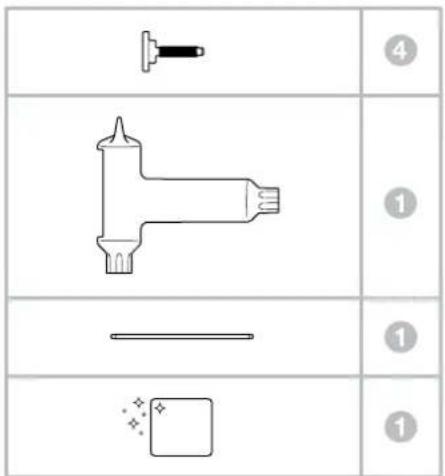
Each pair of speakers are supplied with:
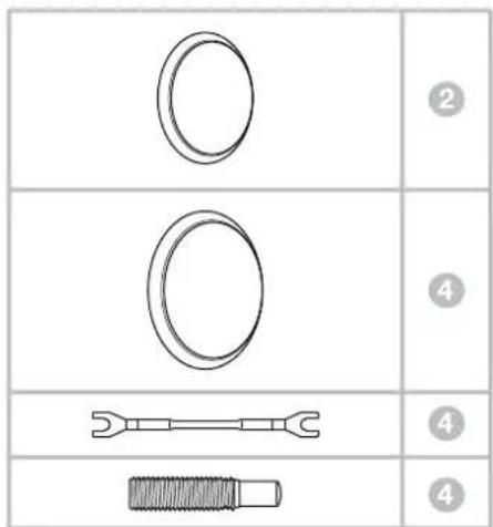
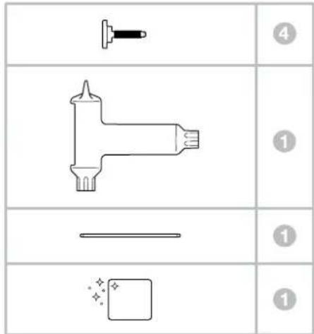
2 Midrange grilles
4 Bass grilles
4 Terminal link wires
4 Stabilisers
4 Stabiliser caps
1 T45 stabiliser adjustment and midrange end cap removal wedge tool
1 Metal spike adjustment bar
1 Cleaning cloth
The 801 D4, 802 D4 and 803 D4 are very heavy and we strongly suggest that they are unpacked in the room in which they are to be used by two people working together. It is also a sensible precaution to remove jewellery to negate the risk of scratching the speakers' surface finish.
The table above illustrates the component parts that are packed with the 801 D4, 802 D4 and 803 D4. In the unlikely event that anything is missing please contact the retailer from whom you purchased the speakers.

The heavier bass/midrange grilles attach magnetically and are packed in a separate compartment to prevent movement in transit.
Note: Care must be taken when fitting or removing the magnetically attached grilles to avoid marking the product. The grilles will mark the speaker / stand plinth if dropped; you can mitigate against this by covering the plinth when fitting or removing the grilles.
Tweeter diaphragms are very delicate and easily damaged. In the 800 Series Diamond we include a steel grille mesh that can protect the tweeter from many forms of damage. However, you should still exercise care when handling and cleaning your loudspeakers.
Environmental Information
This product complies with international directives, including but not limited to:
i. the Restriction of Hazardous Substances (RoHS) in electrical and electronic equipment, ii. the Registration, Evaluation, Authorisation and restriction of Chemicals (REACH) iii. the disposal of Waste Electrical and Electronic Equipment (WEEE).
Consult your local waste disposal authority for guidance on how properly to recycle or dispose of this product.
The tweeter assembly on this 800 Series Diamond loudspeaker is a decoupled component that is mechanically isolated from the main part of the cabinet. As such, it may appear to be loose when the product is first removed from its packaging. This is not a fault, it is an inherent feature of the design and ensures optimum performance from your speaker.
If the tweeter assembly has moved during transit and requires adjustment, the assembly can be moved slightly forwards and backwards to ensure that the rear of the tweeter body is aligned with the rear of the speaker cabinet. The tweeter assembly can also be rotated slightly to ensure that the Bowers & Wilkins logo is vertically orientated. Do not force the tweeter into any position beyond the soft end-stops when making these adjustments.
Note: Care must be taken to not damage the decoupling assembly when making these adjustments - please seek assistance from your dealer if you are in any doubt about adjusting the tweeter assembly.
- Positioning
Speaker Installation
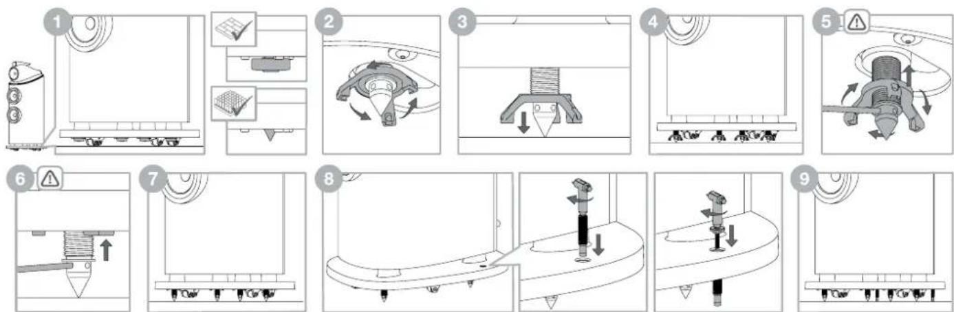
801 D4, 802 D4 and 803 D4 are intended to be floor mounted only and are supplied on wheels to aid with positioning. It is important to ensure that they stand firmly on the floor using the spike feet supplied whenever possible.

Important Safety Notice
spikes, do not touch.
Note: If you are installing the product on very thick carpet such that the wheels prevent the speaker from resting solely on the spikes, you may wish to remove the wheels from the bottom of the plinth, using a 5mm hex (Allen) key. Due to the weight of the speakers, removal of the wheels should only be undertaken by two people – one to tilt the speaker sideways and hold it while the other removes the wheels. We recommend that a suitable wedge or block is used to prevent the loudspeaker accidentally failing to the floor whilst removing or refitting the wheels.
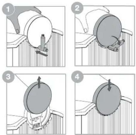
Once the speakers are in the correct position the spikes, inbuilt in the plinth, can be released. Placing your fingers in the gap between the plinth and the floor locate the four spike cups. If your speaker is positioned on a hard floor leave the spike cups in place to protect the flooring. If your speaker is on carpet remove the four spike cups, which are held magnetically, and retain them for future use. This will reveal the spike ready for it to be lowered into position.
Directly above each spike/spike cup you will feel a three pronged locking nut. Using your fingers, spin the locking nut, as directed above in step 2, to lower the spike/spike cup towards the floor. If the locking nut is too tight to turn, insert the supplied metal bar into the hole at the end of one of the prongs and turn; releasing the locking nut (see above illustration).
As the spike/spike cup meets the floor continue to turn the locking nut lifting the speaker off its wheels. Repeat this process with all four spikes/spike cups and adjust the height to ensure the speaker rests firmly without rocking.
To lock the spikes/spike cups in place insert the metal bar into one of the four holes in the spikes. Using the metal bar to stop the spike turning, rotate the locking nut, as directed above in step 5. Once the locking nut is released, remove the metal bar and continue to spin the locking nut returning it to its locked position in the plinth. To ensure the locking nut is tightly locked in place reinsert the metal bar into one of the four holes on the spike. With the metal bar holding the spike in position, use your fingers to turn the locking nut until it can no longer rotate. Repeat this for each spike.
Once the spikes are locked in position, the stabilisers should be fitted to minimise the risk of the loudspeaker being accidentally knocked over. The stabiliser should be threaded through the plinth and lowered into position by using the T45 tool to turn the stabiliser clockwise until the rubber tip rests on the floor.
The stabiliser should not be excessively tightened in order to avoid the spikes being unweighted, which would reduce stability and impair performance. Once the stabilisers are lowered into position the caps can be threaded into the top of the stabiliser and gently tightened with the T45 tool until they rest in the recess in the plinth.
If the speaker needs to be repositioned the stabiliser caps must be removed, the stabilisers raised and the spikes returned back into the plinth before the product is moved. To do this use the T45 tool to remove the stabiliser caps by turning anticlockwise, then use the T45 tool to raise the stabilisers by turning anticlockwise. Once the stabilisers are raised, insert the metal bar into one of the four holes in the spike, with the metal bar holding the spike in position, use your fingers to turn the locking nut, as directed above in step 2, releasing it. Then continue to spin the locking nut until it can no longer rotate; this will ensure the locking nut and spike are engaged. Now turn the locking nut, as directed above in step 3, and the spike will start ascending back into the plinth. Once the spike has been returned to the plinth replace the spike cup (if removed) and the speaker can now be repositioned.
5 Channels 7 Channels
Speaker Positioning
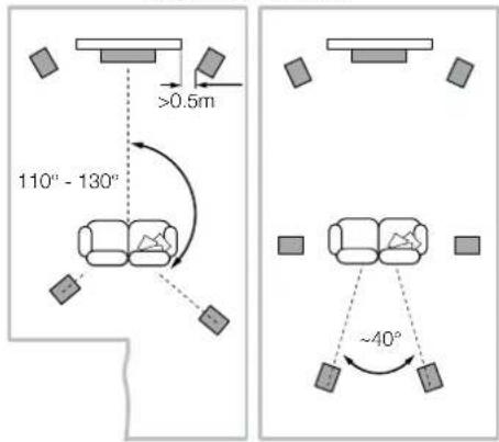
In either stereo or home theatre installations, try to ensure that the immediate surroundings of each speaker are similar in acoustic character. For example, if one speaker is adjacent to bare walls while the other is adjacent to soft furnishings and curtains, both the overall sound quality and the stereo image are likely to be compromised.
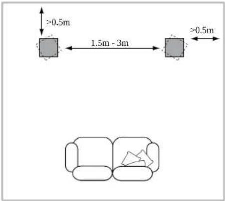
Conventional Stereo Systems
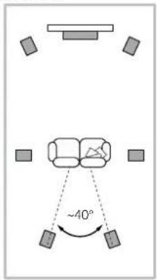
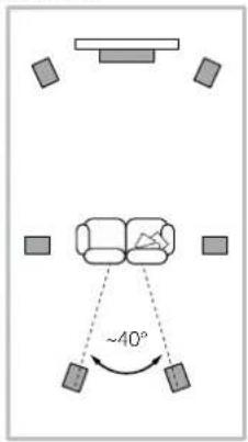
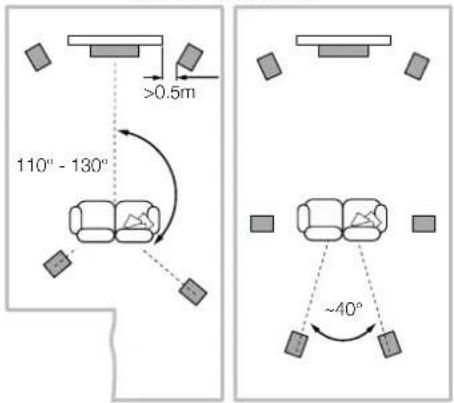
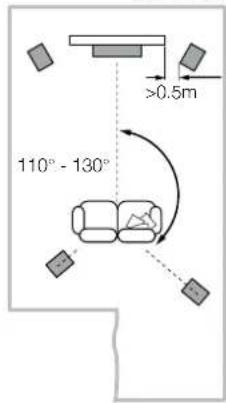
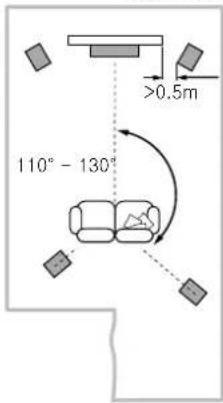
To begin with, the speakers should be positioned between 1.5m and 3m apart at two corners of an equilateral triangle completed by the listening area at the third corner. The speakers should be placed at least 0.5m away from the back and any side walls (as per the illustration above).
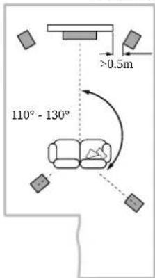
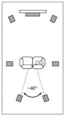
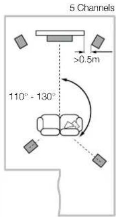
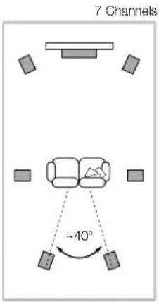
Home Theatre Systems
If the speakers are to be used for the front channels in a home theatre system, they should be placed closer together than for 2-channel audio, because the surround channels tend to widen the image. Positioning the speakers within approximately 0.5m of the sides of the screen will also help keep the sound image in scale with the visual image. As with conventional stereo positioning, the speakers should ideally be at least 0.5m away from any side walls.
- Connecting
Important Safety Notice
All connections should be made with the audio equipment switched off. When using audio equipment in normal operation, touching uninsulated speaker terminals or wiring may result in an unpleasant sensation.
The 801 D4, 802 D4 and 803 D4 speaker terminals accept a variety of cable terminations: 4mm banana plugs, 6mm and 8mm (1/4 in and 5/16 in) spades, or bare wires up to 4mm (5/32 in) diameter.
Important Safety Notice In certain countries, notably those in Europe, the use of 4mm banana plugs is considered a potential safety hazard, because they may be inserted into the holes of unshuttered mains supply sockets. In order to comply with European CENELEC safety regulations, the 4mm holes in the ends of the terminals are blocked by plastic pins. If you are using the products in any country where these conditions apply, you should ensure that any banana plugs cannot be used in an unsafe manner by children or other uninformed persons. The plastic pins can be removed if you wish to use banana plugs.
Ask your dealer for advice when selecting speaker cable. Keep its total impedance below the maximum recommended in the speaker specification and use a low inductance cable to avoid attenuation of high frequencies.
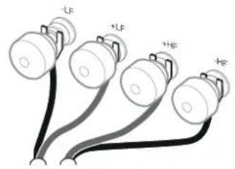

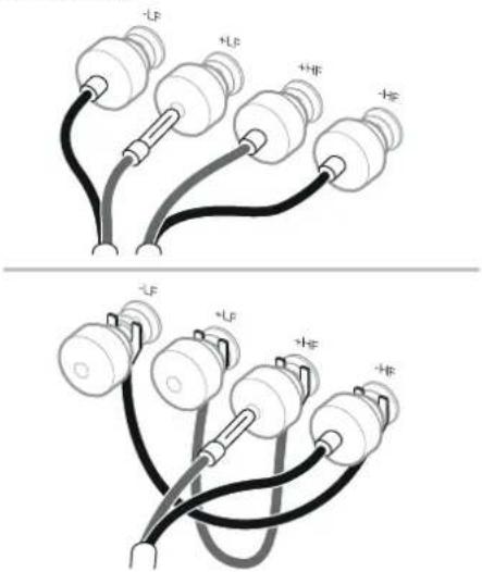
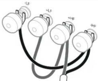
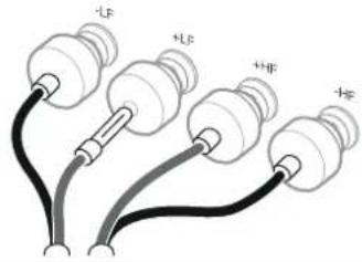
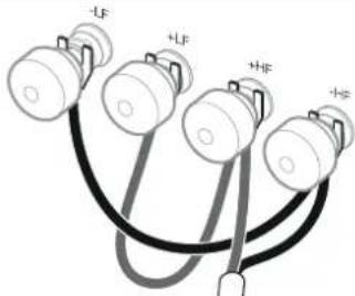
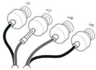
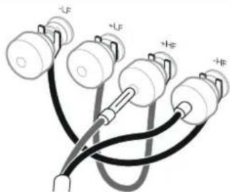
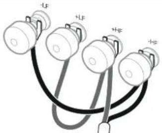
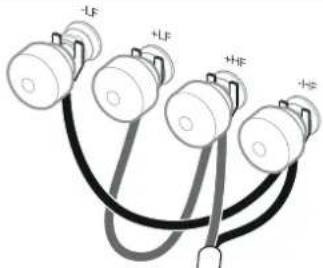
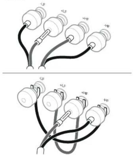
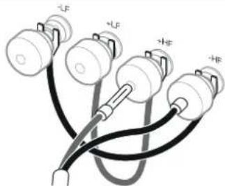
There are two pairs of terminals at the back of each speaker that enable bi-wiring (top left). For single wire connection, fit the supplied link wires to join the like polarity terminals together. Bi-wiring can improve the resolution of low-level detail.
Ensure that the positive terminals on the speaker (with red ring) are connected to the positive output terminal on the amplifier and the negative terminals on the speaker (with black ring) are always connected to the negative output terminal on the amplifier. Incorrect connection will not result in damage but will cause poor stereo imaging and loss of bass. Always screw the terminal caps down fully to prevent rattles.
- Fine Tuning and Running In
Before fine tuning, make sure that all the connections in the installation are correct and secure.
Moving the speakers further from the walls will generally reduce the volume of bass. Space behind the speakers will also help to create an aural impression of depth. Conversely, moving the speakers closer to the walls will increase the volume of bass.
If the bass seems uneven with frequency this will most probably be due to resonance modes in the listening room. Even small changes in the position of the speakers or the listening position can have a profound effect on how these resonances affect the sound. Try moving the listening position or locating the speakers along a different wall. The presence and position of large pieces of furniture can also influence resonance modes.
If the central image lacks focus, try moving the speakers closer together or angle them inward so that they point at a location just in front of the listening position.
If the sound is too bright, increasing the amount of soft furnishing in the room (heavier curtains for example) may help balance the sound. Conversely, reducing the amount of soft furnishing may help brighten a dull sound.
For the most discerning listening, remove the bass/midrange grilles by gripping around their edges and gently pulling them away from the cabinet.
The performance of the speaker will change subtly during the initial listening period. If the speaker has been stored in a cold environment, the damping compounds and suspension materials of the drive units will take some time to recover their correct mechanical properties. The drive unit suspensions will also loosen up during the first hours of use. The time taken for the speaker to achieve its intended performance will vary depending on previous storage conditions and how it is used. As a guide, allow up to a week for the temperature effects to stabilise and 15 hours of average use for the mechanical parts to attain their intended design characteristics.
-
Aftercare
-
Serial Number and Compliance Information
The cabinet surfaces will usually only require dusting. We recommend you use the cloth supplied with the product. If you wish to use an aerosol or other cleaner, apply the cleaner onto the cloth, not directly onto the product and test a small area first, as some cleaning products may damage some of the surfaces. Avoid products that are abrasive, or contain acid, alkali or anti-bacterial agents. Do not use cleaning agents on the drive units. Avoid touching the drive units as damage may result.
Whenever Bowers & Wilkins speakers are finished in real wood, the finest veneers are selected and treated with an ultra-violet resistant lacquer to minimise changes in colour over time. Nevertheless, like all natural materials, the veneer will respond to its environment and a degree of colour change is to be expected. Colour differences may be rectified by exposing all the veneer surfaces equally and evenly to sunlight until the colour is uniform. This process can take several days or even weeks, but may be accelerated by careful use of an ultra-violet lamp. Wood veneered surfaces should also be kept away from direct sources of heat such as radiators and warm air vents in order to minimise the possibility of the wood veneer cracking.
The tweeter housing has a textured surface finish that may collect superficial marks when handled and should be cleaned by wiping the supplied cleaning cloth around the housing, in-line with the surface texture.
The leather covered surfaces of your 800 Series Diamond loudspeaker can be dusted using a soft, dry cloth. Stains can be removed from the leather by moistening a microfibre cloth with warm water and using it to dab the leather until clean. Do not rub the cloth on the leather or use cleaning detergents or leather polish as doing so may cause damage to the product.
In the event that you need to speak with the customer service team about your 800 Series Diamond loudspeakers, you may need to quote the Finished Product (FP) and Serial Numbers that describe your unique loudspeakers. These numbers can be found on both the outer packaging the product was supplied in and under the midrange end cap.
The midrange end cap can be removed by placing one hand on the midrange head to stabilise it, then using the other hand to carefully insert the wedge end of the removal tool in between the end cap and the heatsink. Carefully twist the wedge tool to release the end cap, the end cap can then be slid upwards by hand to reveal the identification numbers and compliance information.
Note: care should be taken not to damage the finish of the end cap, head, heatsink and surrounding parts when removing and refitting the end cap.
The end cap can be replaced by sliding it back onto the mount on the back of the head and pushing gently downward to its resting position.
1. Déballage

natural_image
Diagram of a mechanical device with a cylindrical component and a lever, no visible text or symbols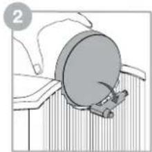
natural_image
Illustration of a mechanical component with a circular component and lever mechanism (no text or symbols)
natural_image
Diagram of a mechanical device with a circular component and an upward arrow, no visible text or symbols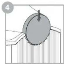
natural_image
Diagram showing a circular object being lifted by a downward arrow, resting on a textured surface (no text or symbols)Kartoninhalt
5 Channels 7 Channels

Heimkinosysteme

natural_image
Diagram of a mechanical device with a cylindrical component and a base, no visible text or symbols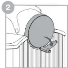
natural_image
Illustration of a mechanical component with a circular component and lever, no visible text or symbols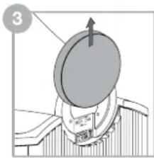
natural_image
Diagram of a mechanical component with a circular component and an upward arrow, no visible text or symbols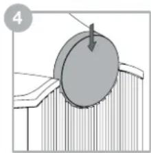
natural_image
Diagram showing a circular object being lifted by a downward arrow, with no visible text or symbolsConteúdos da caixa
5 Channels 7 Channels


Posizionamento
5 Channels 7 Channels

Sistemi Home Theatre

Inhoud doos
Luidsprekeropstelling
5 Channels 7 Channels
Home Theater Systemen
5 Channels 7 Channels

- Συνδέσεις

Содержание упаковки
5 Channels 7 Channels

- Подсоединение

Obsah balení
Pozice reprosoustav
5 Channels 7 Channels
Domácí kino

5 Channels 7 Channels

Ustawienie głośnika
5 Channels 7 Channels


Karton Kutu içeriği
5 Channels 7 Channels

Ev Sineması Sistemi

包装箱内的物品
每对扬声器都配备:
2个中音网罩
4个低音网罩
4根端子连接线
4个稳定器
4个稳定器盖
扬声器的定位
5 Channels 7 Channels
家庭影院系统
包装箱内的物品
每對揚聲器均配有:
2個中音網罩
4個低音網罩
4根端子連接線
4個固定器
4個固定器蓋
揚聲器的定位
5 Channels 7 Channels

家庭影院系統
重要安全指示

内容物
各ペアーのスピーカーの付属品
ミッドレンジグリル2枚
バスグリル4枚
リンクワイヤーケーブル(4本)
スタビライザー4本
スタビライザーキャップ4本
- 接続
スピーカー設置位置
- 微調整と慣らし運転
natural_image
Diagram of a mechanical device with a circular component and a tool, no visible text or symbols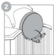
natural_image
Diagram of a mechanical component with a circular component and attached parts, no visible text or symbols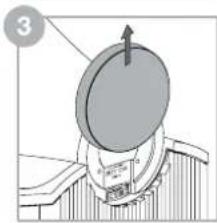
natural_image
Diagram of a mechanical device with a circular component and an upward arrow, no visible text or symbols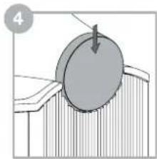
natural_image
Diagram showing a circular object being inserted into a layered material (no text or symbols)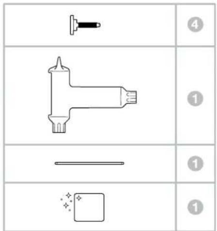
내용물
스피커 설치 위치
5 Channels 7 Channels
홈씨어터 시스템
중요한 안전 지침
Worthing West Sussex
BN11 2BH England
EU Importer:
Bowers & Wilkins
Beemdstraat 11
5653 MA Eindhoven
The Netherlands
Copyright © B&W Group Ltd. E&OE
Printed in England

- Welcome and thank you for choosing
- Carton Contents
- Environmental Information
- Speaker Installation
- Important Safety Notice
- Speaker Positioning
- Conventional Stereo Systems
- Home Theatre Systems
- Déballage
- Kartoninhalt
- Heimkinosysteme
- Conteúdos da caixa
- Posizionamento
- Sistemi Home Theatre
- Inhoud doos
- Luidsprekeropstelling
- Home Theater Systemen
- Содержание упаковки
- Obsah balení
- Pozice reprosoustav
- Domácí kino
- Ustawienie głośnika
- Karton Kutu içeriği
- Ev Sineması Sistemi
- 包装箱内的物品
- 扬声器的定位
- 家庭影院系统
- 揚聲器的定位
- 家庭影院系統
- 重要安全指示
- 内容物
- スピーカー設置位置
- 내용물
- 스피커 설치 위치
- 홈씨어터 시스템
- 중요한 안전 지침
Brand : BOWERS & WILKINS
Model : 801 D4
Category : Speaker