
PlastCoat 1030 - Cement mixer WAGNER - Free user manual and instructions
Find the device manual for free PlastCoat 1030 WAGNER in PDF.
| Product type | Mortar spraying machine for plasters and mineral coatings |
| Brand | Wagner |
| Model | PlastCoat 1030 |
| Dimensions (L x W x H) | 1150 x 520 x 610 mm |
| Weight | 59 kg (base unit) |
| Power supply | 230 V~, 50/60 Hz, 16 A (slow) |
| Motor power (P1) | 2.3 kW |
| Max. working pressure | 40 bar |
| Max. flow rate (water) | 10, 15 or 20 l/min depending on rotor/stator |
| Max. grain size | 6 mm |
| Hopper capacity | 50 litres |
| Max. mortar hose length | 40 m (plus 2.5 m hoses) |
| Max. conveying height | 20 m |
| Protection type | IP 54 |
| Sound pressure level | ≤ 70 dB(A) |
| Operation | Screw pump with electric drive, continuously adjustable flow rate (0-10) |
| Controls | Mode selector (A/F/R), flow regulator, emergency stop |
| Included accessories | Spray gun, mortar hose, tool box, nozzles, lubricant |
| Maintenance and cleaning | Hose cleaning with cleaning sponge, rotor/stator lubrication, seal check |
| Safety | Emergency stop, overload protection, pressure gauge, reinforced mortar hose (40 bar) |
| Spare parts and repairability | Rotor, stator, seals, nozzles, hose available; parts list in manual; repair by Wagner service |
| Warranty | 36 months (professional use) with online registration; 12 months for intensive use |
| General information | Professional use, CE compliant, WEEE Directive 2012/19/EU |
Frequently Asked Questions - PlastCoat 1030 WAGNER
User questions about PlastCoat 1030 WAGNER
0 question about this device. Answer the ones you know or ask your own.
Ask a new question about this device
Download the instructions for your Cement mixer in PDF format for free! Find your manual PlastCoat 1030 - WAGNER and take your electronic device back in hand. On this page are published all the documents necessary for the use of your device. PlastCoat 1030 by WAGNER.
USER MANUAL PlastCoat 1030 WAGNER
natural_image
Technical line drawing of a manual sprayer machine with wheels and control components (no text or symbols)PLASTCOAT 1030
natural_image
Line drawing of a mechanical device on an inclined plane, no text or symbols presenttext_image
Technical diagram of a portable pump launcher system with labeled components and wiring details4.1 BEDIENELEMENTE UND ANZEIGEN AM GERÄT
natural_image
Technical line drawing of a pressure vessel with wheels and internal components (no text or symbols)C330 Ansaugvolumen 330 l/min
Hinweis:
natural_image
Technical line drawing of a mechanical device with no visible text or symbols4.4 MÖRTELSCHLAUCH
text_image
Technical diagram of a mechanical device with numbered components for identification5 TRANSPORT
5.1 FAHREN
natural_image
Line drawing of a manual plow or耙 machine with a crane lifting a component (no text or symbols)5.3 TRANSPORT IM FAHRZEUG
text_image
Technical diagram of a manual pump assembly with numbered parts labeled 1 to 5
text_image
⑥ 8 POWER ERROR F A R SPEED 6 7 9text_image
Technical diagram of a mechanical device with labeled parts, showing fluid flow path and component connections.
text_image
WAFNER 1 2 3 ⑧
text_image
9 AENER 4text_image
Technical diagram of a mechanical device with numbered parts labeled 1 through 10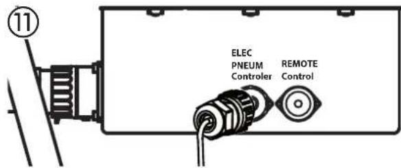
text_image
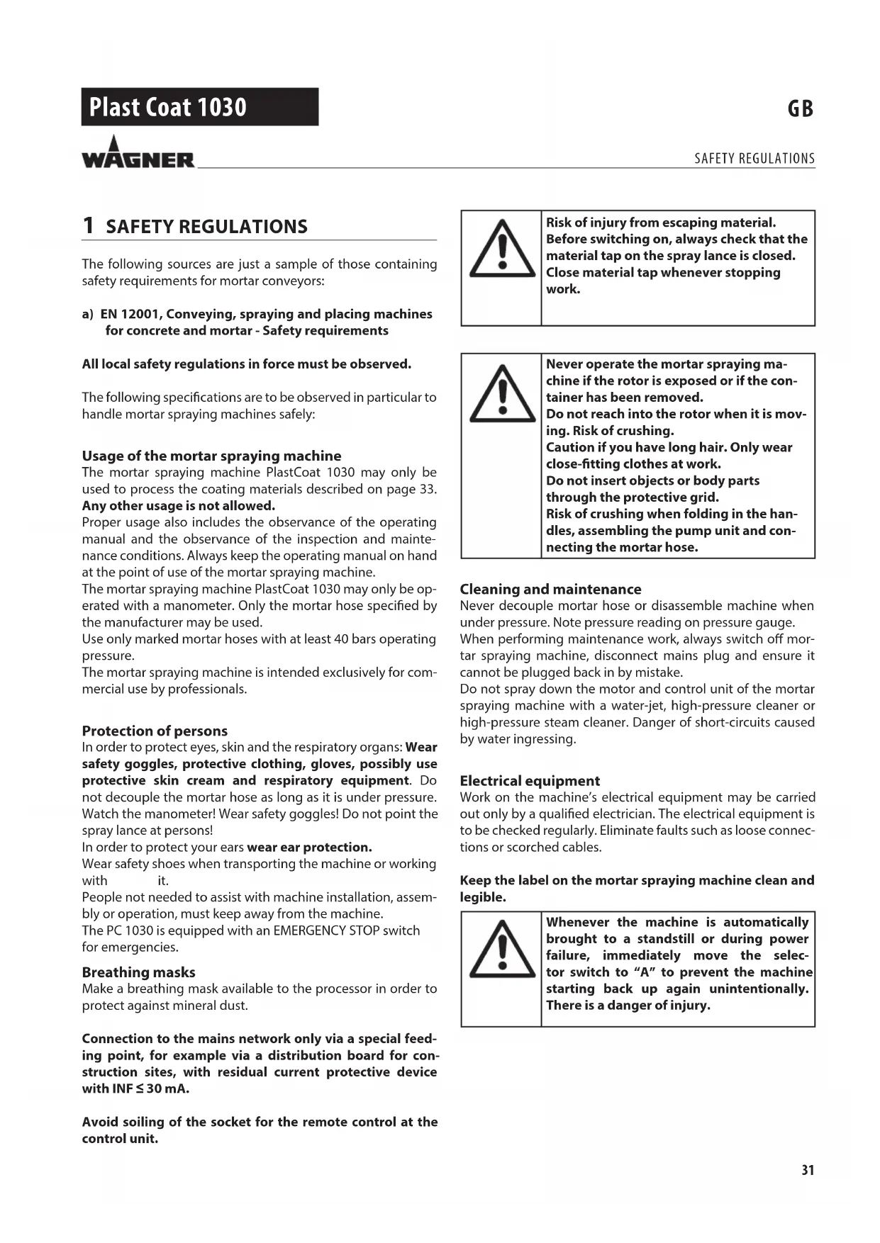
11 ELEC PNEUM Controller REMOTE Control12

text_image
Technical diagram of a device rear panel with labeled ports and buttons⑬
text_image
⑬ 1 26.8 BEGINN DES SPRITZVORGANGS
natural_image
Technical line drawing of a mechanical device with labeled parts (1 and 15), showing internal components without any readable text or symbols.9 WARTUNG

text_image
Technical diagram of a mechanical device with numbered parts and control panel labels9.5 AUSTAUSCH ROTOR (ABB. 17)
text_image
Technical diagram of a mechanical device with labeled parts 1 and 6, showing components like rollers, gears, and shafts.text_image
Technical diagram of a mechanical device with numbered parts for identificationtext_image
Technical diagram of a mechanical vehicle with numbered components for identification12 ERSATZTEILLISTE SPRITZLANZE
POS. BESTELL-NR. BENENNUNG
text_image
Exploded view diagram of a mechanical device with numbered parts for identification13 ZUBEHÖR PLASTCOAT 1030
POS. BESTELL-NR. BENENNUNG
text_image
Exploded view diagram of a mechanical device with numbered parts for identificationSERVICENETZ IN DEUTSCHLAND
Division Professional Finishing
Otto Lilienthal Strasse 18
88677 Markdorf
Translation of the original operating instructions
Warning!
Mortar spraying machines develop high spraying pressures.
| Attention – Danger of injury! | |
| 1 | Never reach into the spray jet with your fingers or hand!Never point the spray lance at yourself or other persons!Coating materials are caustic or irritating!Protect your skin and eyes! |
| 2 | The following points are to be observed in accordance with the operating manual before every start-up:1. Observe the permissible pressures.2. Check all the connecting parts for leaks. |
| 3 | Instructions for regular cleaning and maintenance of the machine are to be observed strictly.Observe the following point before any work on the machine and at every working break:1. Observe the curing time of the coating material.2. Depressurize the spray lance and mortar hose.3. Switch off the suction pump. |
Ensure safety!
Table of Contents
1 SAFETY REGULATIONS 31
2 INTRODUCTION TO WORKING WITH THE MORTAR SPRAYING MACHINE PLASTCOAT 1030 33
2.1 Function of the mortar spraying machine PlastCoat 1030____33
2.2 Processible coating materials 33
3 TECHNICAL DATA 33
4 EXPLANATORY DIAGRAM FOR PLASTCOAT 1030 34
4.1 Operating elements and displays on device ____ 35
4.2 Drive 35
4.3 Compressor (accessory) 36
4.4 Mortar hose 36
4.5 Spray lance 36
5 TRANSPORTATION 37
5.1 Moving 37
5.2 Transport using a crane (fig. 4) ____ 37
5.3 Transportation in vehicle 37
6 COMMISSIONING 37
6.1 Installation location 37
6.1.1 Connection to mains power supply/ Extension cable 37
6.2 Initial starting-up 37
6.2.1 Scope of supply 37
6.2.2 Assembly (fig. 5) 38
6.3 Connecting the mortar hose ____ 38
6.4 Compressor (accessory) 39
6.5 Spray attachment assembly (accessories) ____ 39
6.6 Connecting the spray lance (fig. 10) ____ 39
6.7 Preparing the mortar spraying machine (fig. 12) ____ 40
6.7.1 Rinse the mortar hose 40
6.8 Beginning of the spraying process ____ 41
6.9 End of the spraying process ____ 41
7 GENERAL INFORMATION ABOUT THE APPLICATION TECHNIQUE 42
7.1 Spraying technique 42
8 SHUTTING DOWN AND CLEANING 42
8.1 Cleaning the mortar hose 42
8.2 Cleaning the device and replacing the stator ____ 42
8.3 Cleaning the spray lance 44
9 MAINTENANCE 44
9.1 Mechanical maintenance 44
9.2 Electrical maintenance 44
9.3 Long periods of non-usage 44
9.4 Shaft seal (fig. 16) 45
9.5 Rotor replacement 45
10 ELIMINATING FAULTS 46
11 SPARE PARTS LIST FOR PLASTCOAT 1030 ____ 50
11.1 Spare parts list frame ____ 50
12 SPARE PARTS LIST OF SPRAY LANCE 50
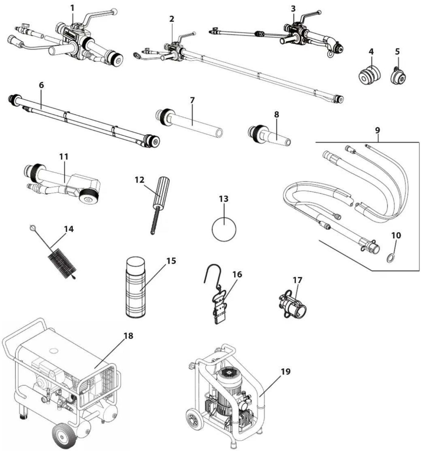
13 PLASTCOAT 1030 ACCESSORIES ____ 52
Testing of the mortar spraying machine ____ 54
Note on disposal 54
Important information on product liability 54
Guarantee declaration 54
CE declaration of conformity 55
European service network 112
1 SAFETY REGULATIONS
The following sources are just a sample of those containing safety requirements for mortar conveyors:
a) EN 12001, Conveying, spraying and placing machines for concrete and mortar - Safety requirements
All local safety regulations in force must be observed.
The following specifications are to be observed in particular to handle mortar spraying machines safely:
Usage of the mortar spraying machine
The mortar spraying machine PlastCoat 1030 may only be used to process the coating materials described on page 33.
Any other usage is not allowed.
Proper usage also includes the observance of the operating manual and the observance of the inspection and maintenance conditions. Always keep the operating manual on hand at the point of use of the mortar spraying machine.
The mortar spraying machine PlastCoat 1030 may only be operated with a manometer. Only the mortar hose specified by the manufacturer may be used.
Use only marked mortar hoses with at least 40 bars operating pressure.
The mortar spraying machine is intended exclusively for commercial use by professionals.
Protection of persons
In order to protect eyes, skin and the respiratory organs: Wear safety goggles, protective clothing, gloves, possibly use protective skin cream and respiratory equipment. Do not decouple the mortar hose as long as it is under pressure. Watch the manometer! Wear safety goggles! Do not point the spray lance at persons!
In order to protect your ears wear ear protection.
Wear safety shoes when transporting the machine or working with it.
People not needed to assist with machine installation, assembly or operation, must keep away from the machine.
The PC 1030 is equipped with an EMERGENCY STOP switch for emergencies.
Breathing masks
Make a breathing mask available to the processor in order to protect against mineral dust.
Connection to the mains network only via a special feeding point, for example via a distribution board for construction sites, with residual current protective device with INF ≤ 30 mA.
Avoid soiling of the socket for the remote control at the control unit.

Risk of injury from escaping material. Before switching on, always check that the material tap on the spray lance is closed. Close material tap whenever stopping work.

Never operate the mortar spraying machine if the rotor is exposed or if the container has been removed.
Do not reach into the rotor when it is moving. Risk of crushing.
Caution if you have long hair. Only wear close-fitting clothes at work.
Do not insert objects or body parts through the protective grid.
Risk of crushing when folding in the handles, assembling the pump unit and connecting the mortar hose.
Cleaning and maintenance
Never decouple mortar hose or disassemble machine when under pressure. Note pressure reading on pressure gauge.
When performing maintenance work, always switch off mortar spraying machine, disconnect mains plug and ensure it cannot be plugged back in by mistake.
Do not spray down the motor and control unit of the mortar spraying machine with a water-jet, high-pressure cleaner or high-pressure steam cleaner. Danger of short-circuits caused by water ingressing.
Electrical equipment
Work on the machine's electrical equipment may be carried out only by a qualified electrician. The electrical equipment is to be checked regularly. Eliminate faults such as loose connections or scorched cables.
Keep the label on the mortar spraying machine clean and legible.

Whenever the machine is automatically brought to a standstill or during power failure, immediately move the selector switch to "A" to prevent the machine starting back up again unintentionally. There is a danger of injury.
Mortar hose

Danger of injury through leaking high-pressure hose. Wear and tear and links as well as usage that is not appropriate to the purpose of the device can cause leakages to form in the mortar hose. Liquid can be injected into the skin through a leakage.
Mortar hoses must be checked thoroughly before they are used.
Replace any damaged mortar hose immediately.
Never repair defective mortar hoses yourself!
Avoid sharp bends and folds: the smallest bending radius is about 80 cm.
Do not drive over the mortar hose. Protect against sharp objects and edges.
Never pull on the mortar hose to move the device.
Do not twist the mortar hose.
Lay the mortar hose in such a way as to ensure that it cannot be tripped over.
| Only use WAGNER original-mortar hoses in order to ensure functionality, safety and durability. | |
| The risk of damage rises with the age of the mortar hose.Wagner recommends replacing mortar hoses after 6 years. |
Setup on an uneven surface
The mortar spraying machine must be installed as shown in the diagram below to prevent it slipping. Block front wheels with brakes.
①
natural_image
Technical line drawing of a mechanical pump or launcher system (no text or symbols)2 INTRODUCTION TO WORKING WITH THE MORTAR SPRAYING MACHINE PLASTCOAT1030
The suction pump PlastCoat 1030 is conceived for using and processing ready mixed mineral coating materials. The machine is not designed for use as a cleaning device.
2.1 FUNCTION OF THE MORTAR SPRAYING MACHINE PLASTCOAT 1030
The coating material is supplied by means of the container. The spiral conveyor feeds the coating material to the eccentric screw pump. The suction effect causes the coating material to enter the eccentric screw pump. This pump builds up the pressure required for transportation through the mortar hose. The compressed air required for atomisation is supplied at the spray lance. The mortar spraying machine can be switched on and off using the electric control. This can also be used to control the delivery volume.
A soft even spray pattern can be achieved by means of the smoothly regulated convey capacity of the coating material.
2.2 PROCESSIBLE COATING MATERIALS
• Thermal insulation composite system bonding agent (mineral and artificial resin systems)
• Artificial resin plasters up to 6 mm granular size
• Silicate plasters up to 6 mm granular size
• Silicone resin plasters up to 6 mm granular size
• Mineral final coats up to 6 mm granular size
• Lightweight plaster systems up to 6 mm granular size
- Scraped stucco up to 6 mm granular size
• Thermal insulation plasters
- Restoration plaster
- Porous concrete coating
- Quartz plastic
- Roof coatings
- Fire protection coatings
• Mineral sealing sludges
- Bitumen emulsions
- Armoring filler
• Liquid wood-chip wall paper
• Casement grouting mortar
• Artificial resin rendering base
- Wash primer
• Filling paint, also fibrous
- Elastic coating
• Acoustic plaster, artificial resin bonded
- Fillers, artificial resin bonded
All the coating materials must be suitable for machine processing. Refer to the product data sheet of the coating material to be processed.
Use other coating materials only after agreement with the manufacturer or the WAGNER application technology service.
3 TECHNICAL DATA
PlastCoat 1030
| Voltage: 230 V~, 50/60 Hz | |
| Fusing: 16 A time-lag | |
| Device supply cable: 5 m long, 3 x 2.5 mm | 2 |
| Motor output P_1 : 2.3 kW | |
| Max. convey capacity (water): 10, 15, 20 l/min(depending on the rotor/stator) | |
| Max. operating pressure: 40 bar | |
| Max. granular size: K6 mm | |
| Dimensions L x W x H: | 1150 x 520 x 610 mm |
| Container capacity: | 50 l |
| Weight (PlastCoat 1030): | 59 kg |
| Weight (Spray lance): | 2.1 kg |
| Max. tyre pressure: | 2.5 bar |
| Degree of protection: | IP 54 |
| Max. sound pressure level: | 70 dB (A)* |
| Atomizing air connection: | Rapid action couplingDN 7.2 mm |
| Max. atomizing air pressure: | 10 bar |
| Minimum required compressed air volume: | 320 l/min |
| Max. mortar hose length: | 40 m (and 2.5 m hose whip) |
| Max. delivery height: | 20 m |
* Place of measurement: 1 m distance from unit and 1.60 m above reverberant floor.
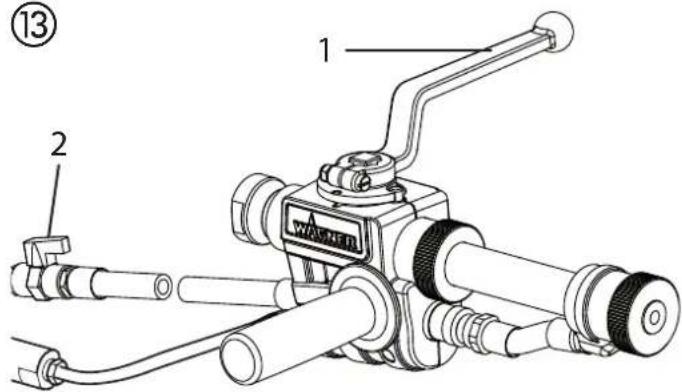
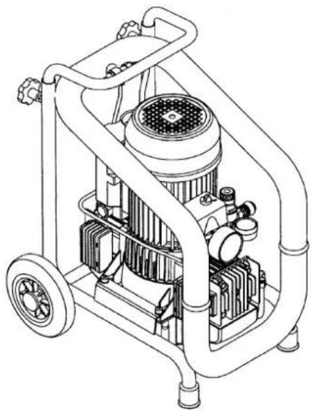
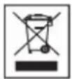
4 EXPLANATORY DIAGRAM FOR PLASTCOAT 1030
1 Control unit
3 Operating light green (indicates that mains voltage is present)
5 EMERGENCY STOP switch 6 Base frame with wheels
7 Remote control connection 8 External controller connection
9 Mortar hose with air hose complete 10 Spray lance
11 Container 12 Loading area
13 Outlet unit with inside screw pump 14 Manometer
15 Connecting coupling for mortar hose 16 Tool box
2 Indicator light red (indicates the presence of a malfunction)
4 Control panel with selector switch for operating mode and delivery volume controller
②
text_image
2 3 POWER ERROR F A R SPEED 1 4 5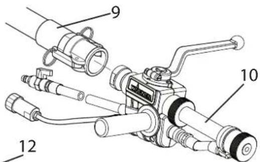
text_image
Technical diagram of a mechanical device with numbered parts labeled 9, 10, and 12
text_image
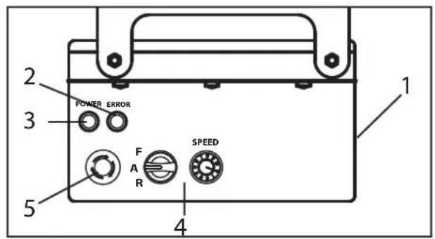
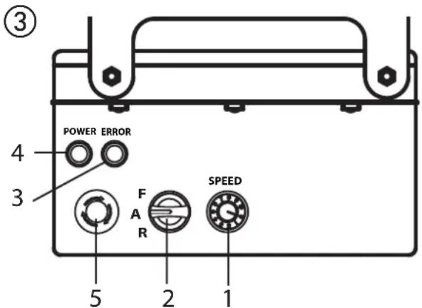
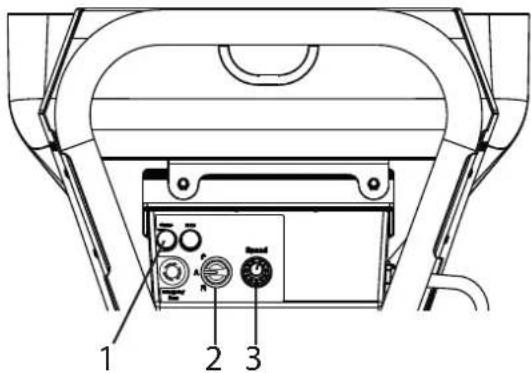
16 6 11 13 14 15 8 7 ELEC PNEUM Controller REMOTE Control4.1 OPERATING ELEMENTS AND DISPLAYS ON DEVICE
1 Delivery volume controller 0-10
2 Selector switch for operating mode
3 Indicator light (Error)
4 Operating light (Power)
5 EMERGENCY STOP switch
text_image
③ POWER ERROR 4 3 F A R SPEED 5 2 1The delivery volume controller (Fig. 3, 1) is used to regulate the convey capacity from 0-10 smoothly.
The selector switch (Fig. 3, 2) offers the following modes:
FA  R R | “A” position = automaticBasic setting for control with an automatic spray lance |
FA  R R | “F” position = manual activationSwitches on the mortar spraying machine.This setting is required for:disassembling the pump unit |
FA  R R | “R” position = reverse gearThis setting is required for:relieving pressure on the mortar hoseassembling the pump unit |
Detailed explanation of selector switch use:
If the selector switch is in the "A" position, the PC 1030 can be switched on and off with the material shut-off on the automatic spray lance.
If there is no spray lance fitted (e.g.: assembly/disassembly the pump unit), the machine is switched on using the "F" switch position and off using the "A" position.

Important: control via the selector switch and material shut-off are treated equally.
The machine can be switched from the "A" position (control using material shut-off) to "F" at any time.
We would therefore recommend that only one person operate the machine.
The operating light (green, Fig. 3, 4) indicates that the machine is energised and ready.
When the mains plug is connected the PC 1030 carries out a function check. While this is going on the indicator light (red, fig. 3.3) flashes. If everything is in working order, the flashing stops after about 30 seconds. If the indicator light lights up during operation, this indicates that there is a malfunction. For detailed information about this kind of fault, refer to the „Rectification of faults“ section on page 46.

If the selector switch is in the "F" position when the mains plug is plugged in, the machine will not switch on.
Briefly move selector switch to "A" and then back to "F" to switch on the machine.
EMERGENCY STOP switch
When the EMERGENCY STOP switch is pressed, the PC 1030 is switched off immediately.
Turn the EMERGENCY STOP switch in order to release it again. The machine remains switched off after release. To switch it on again, the selector switch must be briefly set to "A" and then to "F".
4.2 DRIVE
When an overload occurs, the mortar spraying machine switches off automatically (red indicator light lights up).
Move selector switch (Fig. 3, 2) to "A" and disconnect mains plug. Set delivery volume controller (Fig. 3, 1) to „0“.
Wait around 5 minutes, then plug the mortar spraying machine back in and switch on. Set the delivery volume required.
| The drive unit heats up during operation. This is normal and not a sign of malfunction. |
4.3 COMPRESSOR (ACCESSORY)
VKM 592 intake volume 590 l/min
Note:
Only operate the compressor in accordance with the enclosed operating manual.

natural_image
Technical line drawing of a pressure vessel with wheels and internal components (no text or symbols)C330 intake volume 330 l/min
Note:
Only operate the compressor in accordance with the enclosed operating manual.
natural_image
Technical line drawing of a mechanical device with pipes and housing (no text or symbols)4.4 MORTAR HOSE
1 Material connection mortar spraying machine
2 Control cable connection / controller
3 Atomizing air connection compressed air supply
4 Material connection spray lance
5 Mortar hose
6 Atomizing air connection spray lance
7 Control cable connection
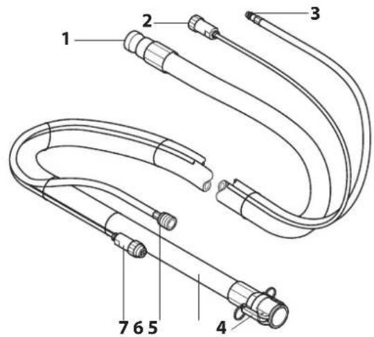
text_image
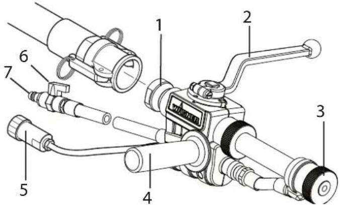
1 2 3 4 7 6 54.5 SPRAY LANCE
1 Material connection
2 Combined material and air tap:
Open: material tap at 90° to spray lance
Closed: material tap points forwards
3 Texture tip:
Various texture tips can be used in the spray lance. The tip size depends on the granular size of the coating material and the desired spray pattern.
4 Hand-grip:
The hand-grip can mounted to either the right or left side of the spray lance, depending on what is required. The thread on the other side can be closed by way of the attached stoppers for protection.
5 Control cable connection
6 Air flow regulator
7 Atomization air connection
text_image
Technical diagram of a mechanical device with numbered components for identification5 TRANSPORTATION
5.1 MOVING
Wind power cable around handle and remove the hose. Put away the nozzles and other small objects in the storage compartment. Push or pull the PC 1030 by the handle.

Make sure that 2 people are available to carry the device on stairs.
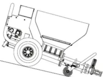
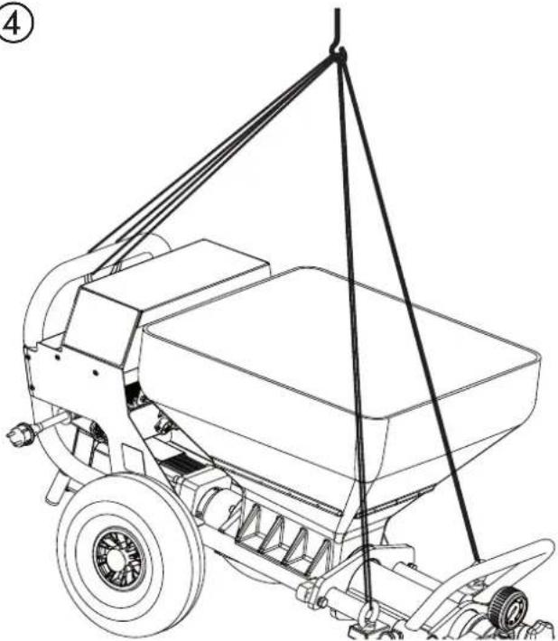
5.2 TRANSPORT USING A CRANE (FIG. 4)
For attaching points for the straps or rope (not wire cable) see figure.
④
natural_image
Line drawing of a manual sprayer machine with a crane lifting a component (no text or symbols)5.3 TRANSPORTATION IN VEHICLE
Secure the unit in the vehicle by means of suitable fasteners.

To avoid material residues leaking from the machine, clean the device in advance or lock the mortar connection.
6 COMMISSIONING
6.1 INSTALLATION LOCATION
Position mortar spraying machine in a level position to prevent it from sliding away.
6.1.1 CONNECTION TO MAINS POWER SUPPLY/ EXTENSION CABLE
Connection to the mains network only via a special feeding point, for example via a distribution board for construction sites, with residual current protective device with INF ≤ 30 mA.

Lay the device supply cable so that there is no danger of stumbling.
Protect against damage, for example against being driven over.

Min. wire cross-section 3 x 2.5 mm ^4 . Unroll the extension cable completely. Ensure that the coupling pieces and plugs are free of damage.
- Before connecting the unit to the mains supply, ensure that the line voltage matches that specified on the rating plate.
6.2 INITIAL STARTING-UP
6.2.1 SCOPE OF SUPPLY
The machine is supplied by the manufacturer in the following individual components:
- Complete basic machine comprising drive unit, control unit, receptacle and transport frame with wheels
- Stator
- Hose package
- Spray lance
- Pump sliding means
- Tool box with nozzles, cleaning accessories,...
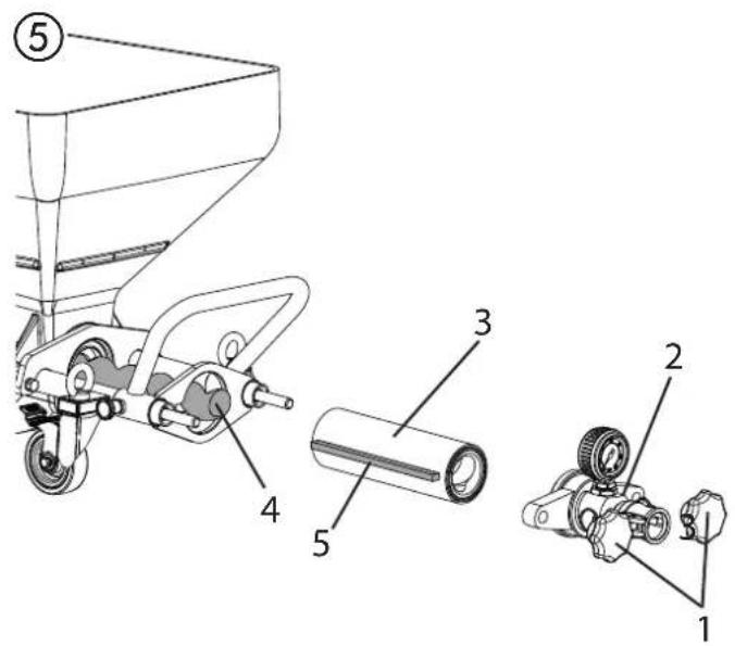
6.2.2 ASSEMBLY (FIG. 5)
| Disconnect external controls. Assembly may only be carried out by the person who controls the machine.Never operate mortar spraying machine with an exposed rotor.Do not reach into the rotor when it is moving. Risk of crushing.Caution if you have long hair. Only wear close-fitting clothes at work. |
Loosen the star screws (1) and remove the outlet unit (2). Spray the stator (3) and rotor (4) with a suitable pump lubricant (order no. 9992 824).
Move selector switch (6) to "A" and set delivery volume controller (7) to „0".
Connect mains plug to mains power supply.
The operation light (8) shows operational readiness.
The red indicator light (9) flashes during the function check for about 30 seconds.
Set delivery volume controller (7) to 1 or 2.
Push the stator (3) over the tip of the rotor (4) (guide rail (5)).
Set the selector switch (6) to „R“ to push the stator automatically on to the rotor.
As soon as the stator is in end position, set the selector switch (6) to „A“.
Re-assemble the outlet unit (2) and tighten the star screws (1).
text_image
Technical diagram of a manual push pump with labeled parts including handle, cylinder, and motor assembly
text_image
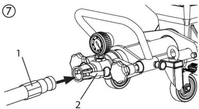
⑥ 8 POWER ERROR F A R SPEED 6 7 96.3 CONNECTING THE MORTAR HOSE
- Check that the pump unit is seated firmly.
- Connect the mortar hose (Fig. 7, 1) and secure it with the clamping levers (Fig. 7, 2).
- Connect the atomizing air connection at the mortar hose to the compressed air supply, for example the compressor (accessory).
text_image
Technical diagram of a mechanical device with labeled parts, showing hoses and tubing connections6.4 COMPRESSOR (ACCESSORY)
Place the compressor at a secure location next to the mortar spraying machine and connect it to the mains network.
Note:
Only operate the compressor in accordance with the enclosed operating manual.
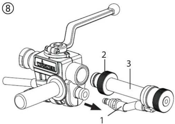
6.5 SPRAY ATTACHMENT ASSEMBLY (ACCESSORIES)

Different accessories can be mounted to the spray lance, depending on the application, e.g. an extension can be attached. A precise overview can be found in the "Accessories" chapter.
- Disengage the quick connector and pull the air hose (fig. 8, 1) out of the lance.
- Loosen the locknut (2) and remove the material hose (3).
- Insert the material hose and air hose (if available), which are part of the accessory, into the spray lance and secure by tightening the locknut. (Fig. 9)
Attention: Make sure the O-ring (fig. 9, 4) is not damaged.
6.6 CONNECTING THE SPRAY LANCE (FIG. 10)
- Select a spray tip suitable for the material:
The tip size should amount to at least three times the granular size, e.g.
granular size artificial resin plasters -> 3 mm
Tip size -> 10 mm
- Mount the texture tip (1) in the spray lance with the cone pointing towards the spray head.
- Connect the spray lance (2) to the material hose and secure by applying the levers (3).
- Close the material tap (4) (material tap points forwards).
- Connect atomization air connection (5) to the air hose of the mortar hose.
- Screw coupling plug (6) for remote control to the control cable of the mortar hose.
- Connect mortar hose's control cable to pump connection. (Fig. 11)
- Set selector switch to "A".
text_image
WASHER 2 3 1 ⑧
text_image
9 AGNER 4
text_image
Technical diagram of a mechanical device with numbered parts labeled 1 through 10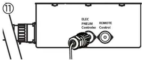
text_image
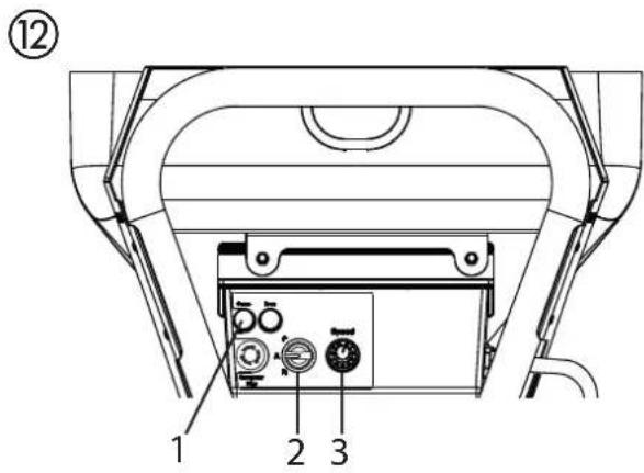
11 ELEC PNEUM Controller REMOTE Control6.7 PREPARING THE MORTAR SPRAYING MACHINE (FIG. 12)
Recommended sliding means for the mortar hose
| Water is not sufficient as a sliding means. Danger of clogging! Use cellulose paste (e.g. Metylan wallpaper paste, art no. 2312136) |
- Fill 2–3 I cellulose paste into the container.
- Connect the mortar spraying machine to the mains supply. The operation light (1) shows operational readiness.
| Risk of injury from escaping material.Before switching on, always check that the material tap on the spray lance is closed (material tap points forwards).Close material tap whenever stopping work. |
- Set selector switch (2) to "A".
- Set delivery volume controller (3) to „3“.
6.7.1 RINSE THE MORTAR HOSE
- Close the air flow regulator (fig. 13.2).
| Do not bend the mortar hose!Protect it against damage, for example against being driven over as well as against sharp objects and edges. |
- Hold spray lance over an empty bucket.
- Open material tap (Fig. 13, 1) on spray lance (material tap at 90^ to spray lance), the mortar spraying machine is switched on.
- If cellulose paste comes out of the tip, close the material tap (fig. 13, 1) (material tap points forwards).
- Fill coating material into the receptacle.
| With mineral coating materials only fill the receptacle to half full. |
- Position the spray lance over the bucket again.
- Replace container and lubricant with container and coating material.
- Hold spray lance above container with cellulose paste.
- Open material tap (Fig. 13, 1) on spray lance.
- As soon as coating material exits from spray lance, close material tap (Fig. 13, 1).
The mortar spraying machine is now full and ready.
text_image
⑫ 1 2 3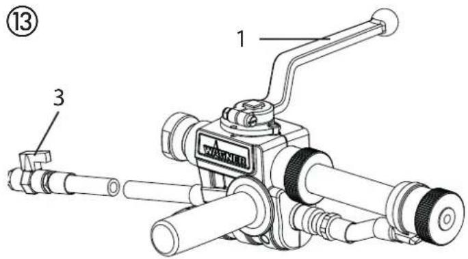
text_image
13 3 WAGNETD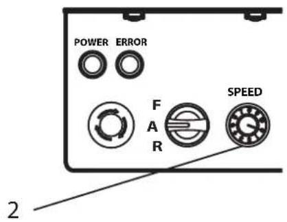
text_image
POWER ERROR F A R SPEED 26.8 BEGINNING OF THE SPRAYING PROCESS
- Open the air flow regulator (fig. 13, 3) and the material tap (13, 1) at the spray lance.
- Adjust the flow of material with the delivery volume controller (fig. 13, 2) on the control unit and set the air quantity by adjusting the air flow regulator (fig. 13, 3) to attain the desired spray pattern.
| Important: Do not let the mortar spraying machine run dry. Switch the device off immediately if no more material comes out of the tip or if the spray line becomes irregular. Possible reasons for the problem and how to correct it can be found in the chapter called „Eliminating faults“. | |
| Increased material tap wear. Do not use the material tap to set the material volume. The delivery volume controller should be used for this purpose. |
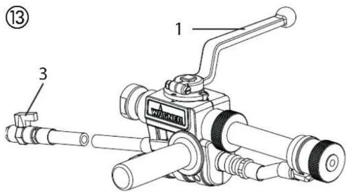
6.9 END OF THE SPRAYING PROCESS
- Close the material tap (Fig. 13, 1).
- Close the air flow regulator (fig. 13, 3).
| Always close material tap at end of the spray process. |
text_image
⑬ 1 3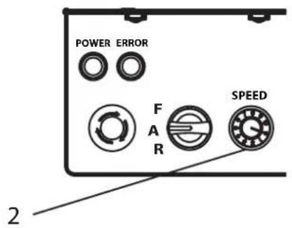
text_image
POWER ERROR F A R SPEED 27 GENERAL INFORMATION ABOUT THE APPLICATION TECHNIQUE
7.1 SPRAYING TECHNIQUE
While spraying hold the spray lance at a uniform distance of 30 – 60 cm from the object. Otherwise the spray pattern will be uneven.
The spray pattern depends on the coating material, viscosity, tip size, convey capacity and amount of atomizing air.
Examples:
Fine texture -> large amount of atomizing air Rough texture -> small amount of atomizing air Higher convey capacity -> larger amount of atomizing air
Test the desired texture on a test surface.
The lateral limit of the spray jet should not be too sharp. The distance between the spray lance and the object should therefore be selected correspondingly.
The spray edge should be gradual in order to facilitate overlapping of the next coat.
If the spray lance is moved parallel and at an angle of 90^ to the surface to be coated, the paint mist is minimized.
Note:
Grains and pigments with a sharp edge result in a high rate of wear of the pump, mortar hose, material tap and tip.

When using the mortar hose while working on scaffolding, it is best to always guide the hose along the outside of the scaffolding.
8 SHUTTING DOWN AND CLEANING

Do not clean the motor and control unit of the mortar spraying machine moistly. And certainly do not spray down the unit with high-pressure cleaners or high-pressure steam cleaners. Danger of short-circuits caused by water ingressing.
8.1 CLEANING THE MORTAR HOSE
- Pump until receptacle is empty.

Important: Do not let the mortar spraying machine run dry. Switch the device off immediately if no more material comes out of the tip or if the spray line becomes irregular. Possible reasons for the problem and how to correct it can be found in the chapter called „Eliminating faults“.
- Switch off mortar spraying machine and compressor.
- Close material tap on spray lance.
- Remove the texture tip from the spray lance and clean it.
- Put water in the container and hold the spray lance over an empty bucket.
Important: Do not let the mortar spraying machine run dry. During the cleaning process, ensure that there is always enough water in the container.
- Set delivery volume controller to „5“.
- Open material tap on spray lance.
- Pump material out of hose into container until the material exiting the hose is just a thin liquid.
- Close material tap on spray lance.

The mortar hose must be pressureless. If necessary, set the selector switch briefly to "R" (reverse). Watch the manometer --> 0 bar. Wear safety goggles.
• Decouple mortar hose from pump unit.
• Decouple spray lance from mortar hose.
- Insert cleaning ball into mortar hose and reconnect mortar hose
- Set selector switch to "F".
• After a few seconds the cleaning ball is emitted from the spray lance.
- Depending on the processed coating material, repeat the cleaning process 3 – 4 times.

The mortar hose must be pressureless. If necessary, set the selector switch briefly to "R" (reverse). Watch the manometer --> 0 bar. Wear safety goggles.
- Set selector switch to "A".
• Decouple mortar hose from pump unit.

A further cleaning option is to use the cleaning adapter (accessory). This cleaning adapter can be connected to a water hose or a tap by means of the claw coupling. Insert cleaning ball into the mortar hose. Couple the mortar hose to the cleaning adapter and rinse through with water.
8.2 CLEANING THE DEVICE AND REPLACING THE STATOR
- Clean mortar spraying machine. To do so, pump a suitable pump lubricant or water mixed with washing-up liquid through the pump.
Dismantling
| Mortar spraying machine must be depressurised.If necessary, set the selector switch briefly to “R” (reverse).Watch the manometer --> 0 bar.Wear safety goggles. |
| Disconnect external controls. Disassembly may only be carried out by the person who controls the machine.Never operate mortar spraying machine with an exposed rotor.Do not reach into the rotor when it is moving. Risk of crushing.Caution if you have long hair. Only wear close-fitting clothes at work. |
- Move selector switch (fig. 14, 1) to "A" and set delivery volume controller (2) to „0".
- Disconnect mains plug.
- Loosen the star screws (3) and remove the outlet unit (4).
- Set delivery volume controller (2) to 1 or 2.
- Connect mains plug to mains power supply.
- Move the selector switch (1) to position „F“. As soon as the stator (5) is released from the rotor (6), set the selector switch to „A“.
- Remove the stator (5) completely.
- Disconnect mains plug.
Clean the outlet unit
Clean the outlet unit (4) with a jet of water and a suitable bottle brush.
Clean the container (7) with a jet of water and a suitable brush. Clean the protective grid with a radiator brush.
Also clean the rotor (6) and stator (5) thoroughly with water and, if necessary, using a brush.
Then spray rotor (6) and stator (5) and with a suitable pump lubricant.
Keep the thread of the pump housing and the pump tube clean so that leaking after the assembly is avoided.
Mounting
| If the machine is down for a longer period of time, the stator can become set at the rotor. Therefore, if the stator has been in storage for a longer period of time, do not mount it until you are about to begin work. |
Assembly, see chapter 6.2.2

text_image
Technical diagram of a mechanical device with numbered parts and labeled control buttons including power, speed, and fan controls.8.3 CLEANING THE SPRAY LANCE
- Clean the texture tip.
- Use cleaning needles to clean the air holes in the texture tip.
- Clean and lubricate the O-ring (fig. 15, 1).
- Clean the spray lance and material tube on the inside using a bottle brush (0342 329).
- Clean all threads thoroughly.
- Rinse the spray lance with clear water. Open and close the material tap three times as you are doing this.
natural_image
Technical line drawing of a mechanical device with labeled parts (1 and 15), showing exploded and assembled views without any readable text or symbols.9 MAINTENANCE

ATTENTION! It is imperative that the machine be deenergized by unplugging the plug before all work and maintenance work. Otherwise there is a danger of short-circuiting!
Repairs may only be carried out by qualified personnel who dispose the corresponding training and experience. The device must be tested by a skilled electrician after every repair.
The mortar spraying machine is designed so that a minimum of care and maintenance is required. However, the following work has to be carried out and components checked regularly:
9.1 MECHANICAL MAINTENANCE
- Keep the thread at the pump tube and pump housing clean and, if appropriate, seal.
- Check the seals at all the couplings and connecting pieces for leaks. If appropriate, replace worn seals.
- Check the following for damage before every usage:
- Mortar hose
- Power cable
- Control unit
- The electrical drive and its ventilation slots must always be kept clean and may not be cleaned with water. Danger of short-circuits.
9.3 LONG PERIODS OF NON-USAGE
If the mortar spraying machine is not used for a longer period, it has to be cleaned thoroughly and protected against corrosion.

Take the stator out of the pump unit so that it cannot get stuck to the rotor.
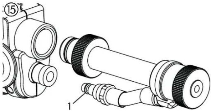
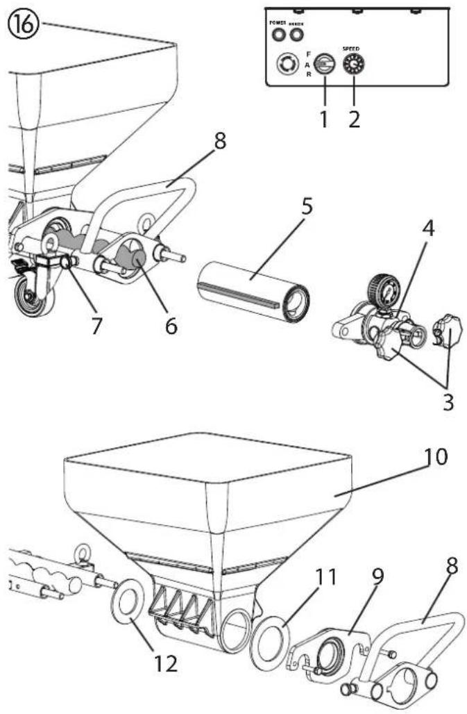
9.4 SHAFT SEAL (FIG. 16)

- Move selector switch (fig. 16, 1) to "A" and set delivery volume controller (2) to „0".
- Disconnect mains plug.
- Loosen the star screws (3) and remove the outlet unit (4).
- Set delivery volume controller (2) to 1 or 2.
- Connect mains plug to mains power supply.
- Move the selector switch (1) to position „F“. As soon as the stator (5) is released from the rotor (6), set the selector switch to „A“.
- Remove the stator (5) completely.
- Disconnect mains plug.
- Pull out the two locking pins (7) and remove the anti-twist lock (8).
- Remove the flange (9) with a 17-wrench.
- Remove the container (10).
- Check the seal (11) and replace if necessary.
- Clean the shaft seal (12).
- Check the rotor (6) and replace if necessary (see chapter 9.5).
9.5 ROTOR REPLACEMENT (FIG. 17)
- Loosen fixing screw (1) and remove old rotor (6).
• Fit new rotor with new fixing screw. - Glue fixing screw with Loctite 243.
| Note: use Loctite 243 only. |

text_image
Technical diagram of a mechanical device with labeled parts 1 and 6, showing components like rollers, gears, and shafts.10 ELIMINATING FAULTS
| MALFUNCTION POSSIBLE CAUSE EL | MINATION | ||
| Mortar spraying machine not running.Green operating light lights up | Delivery volume controller is set to „0“Lance control cable not connected or damaged | Increase delivery volumeCheck control cable | |
| Mortar spraying machine not running.Green operating light not does not light up | Power supply missing. - Plug in the power plug.- Check the power cable for damage and replace, if necessary.- Check the power supply. | ||
| Mortar spraying machine not running.Red indicator light lights up | Mortar spraying machine was over-loaded/overheated. | Close material tap and disconnect mains plug.Switch the mortar spraying machine on again after about 5 minutes. | |
| Mortar spraying machine cannot rotate the rotor | Rotor stuck in stator.Pump was not lubricated with pump sliding means. | Set the selector switch alternatively briefly to “F” (forwards) – “R” (reverse).Contact Wagner customer service if the problem cannot be resolved. | |
| Mortar spraying machine builds up pressure in the mortar hose.However, coating material does not arrive at the spray lance. | Coating material "plug" in the mortar hose. Mortar hose not prerinsed with cellulose paste. | Depressurize the mortar hose – set the selector switch to “R” (reverse).Pump the coating material back into the container. | |
 | The mortar hose must be pressureless.Watch the manometer --> 0 bar.Wear safety goggles. | ||
| Decouple mortar hose and rinse with water hose.When the plug has been removed, fill cellulose paste in the mortar hose. Couple the mortar hose back on. | |||
| Coating material is suddenly not emitted during spraying. | Texture tip is clogged because of impurity in the coating material or because the granular size is too large.Texture tip too small.Coating material "plug" in the mortar hose. Mortar hose not prerinsed with cellulose paste.No coating material in the container.Pump has sucked in air. | Switch the mortar spraying machine off.Close the material cock at the spray lance.Remove the texture tip and clean it.Select a larger texture tip.Rule of thumb: Granular size x 3 --> Tip sizeDepressurize the mortar hose - set the selector switch to "R" (reverse).Pump the coating material back into the container. | The mortar hose must be pres- sureless.Watch the manometer --> 0 bar.Wear safety goggles.Decouple mortar hose and rinse with water hose.When the plug has been removed, fill cellulose paste in the mortar hose. Couple the mortar hose back on.Refill the container with coating material and pump it around until the coating material emerg-es without any bubbles.Attention:Always top up with sufficient coating material.Do not let the pump run dry. Pump overheats, resulting in a danger of „plugs". |
| Spray pattern is not clean and even. | Air ducts in the texture tip are partially closed with coating material.Air volume incorrectly set.Poor mortar spraying machine clean-ingNo coating material in the container.Pump has sucked in air. | Switch the mortar spraying machine off.Close the material tap at the spray lance.Remove the texture tip. Clean the air ducts of the texture tip.Change air volume setting.Thoroughly clean mortar spraying machineRefill the container with coating material and pump it around until the coating material emerg-es without any bubbles.Attention:Always top up with sufficient coating material.Do not let the pump run dry. Pump overheats, resulting in a danger of „plugs". | |
| Pressure at the manometer rises to more than 40 bars. | Viscosity of the coating material too high.Mortar hose diameter too small.Mortar hose is too long.Coating material "plug" in the mortar hose. Mortar hose not prerinsed with cellulose paste. | Dilute the coating material.Use a mortar hose with a larger diameter.Use a shorter mortar hose.Depressurize the mortar hose – set the selector switch to "R" (reverse).Pump the coating material back into the container. | |
 | The mortar hose must be pres- sureless.Watch the manometer --> 0 bar.Wear safety goggles. | ||
| Decouple mortar hose and rinse with water hose.When the plug has been removed, fill cellulose paste in the mortar hose. Couple the mortar hose back on. | |||
| Mortar spraying machine does not pump enough coating ma- terial. | Convey capacity selected too low.Mortar hose diameter too small.Stator worn.Texture tip too small. | Set the volume regulator higher.Use a mortar hose with a larger diameter.Mount a new stator, if necessary, also a new rotor.Attention: Spray on pump sliding means.Select a larger texture tip.Rule of thumb: Granular size x 3 --> Tip size | |
If the defect is not caused by one of the above-mentioned faults, have the defect eliminated by the WAGNER customer service.
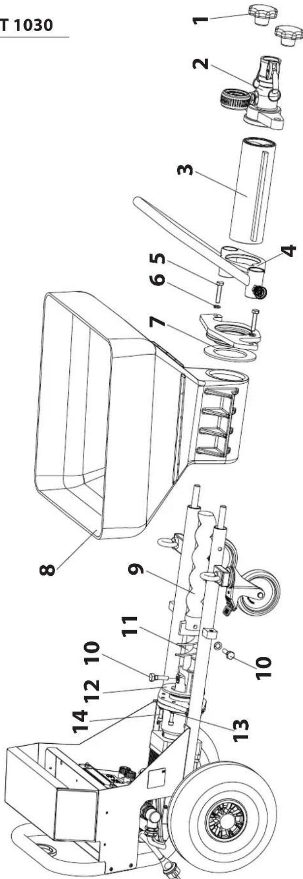
11 SPARE PARTS LIST FOR PLASTCOAT 1030
| ITEM ORDER NO. DESIGNATION | ||
| 8 | 2357594 Receptacle | |
| 9 | 348316 | Rotor |
| 10 | 348324 | Screw |
| 11 2360651 Feeder shaft | ||
| 12 2360706 Rubber seal, motor | ||
| 13 | 9921501 | Spring washer |
| 14 | 9900313 | Cylinder head screw |
| ITEM ORDER NO. DESIGNATION | ||
| 1 | 9990368 | Star knob nut |
| 2 | 2362368 | Outlet unit cpl. |
| 3 | 348315 | Pump casing |
| 4 | 2361120 | Anti-twist lock for stator |
| 5 | 9900247 | Hexagon head screw |
| 6 | 9921507 | Spring washer |
| 7 2360707 Rubber seal, flange | ||
text_image
T 1030 8 14 12 10 11 9 7 6 5 3 2 1 4 13 1011.1 SPARE PARTS LIST FRAME
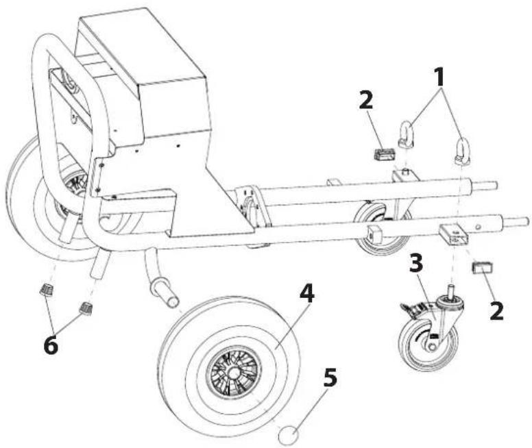
| ITEM | ORDER NO. | DESIGNATION |
| 1 | 3142039 | Ring nut M12 |
| 2 | 3069013 | Square head plug |
| 3 | 2367604 | Guide pulley |
| 4 | 348349 | Wheel |
| 5 | 9994902 | Wheel cap |
| 6 | 2309787 | Protective cap |

text_image
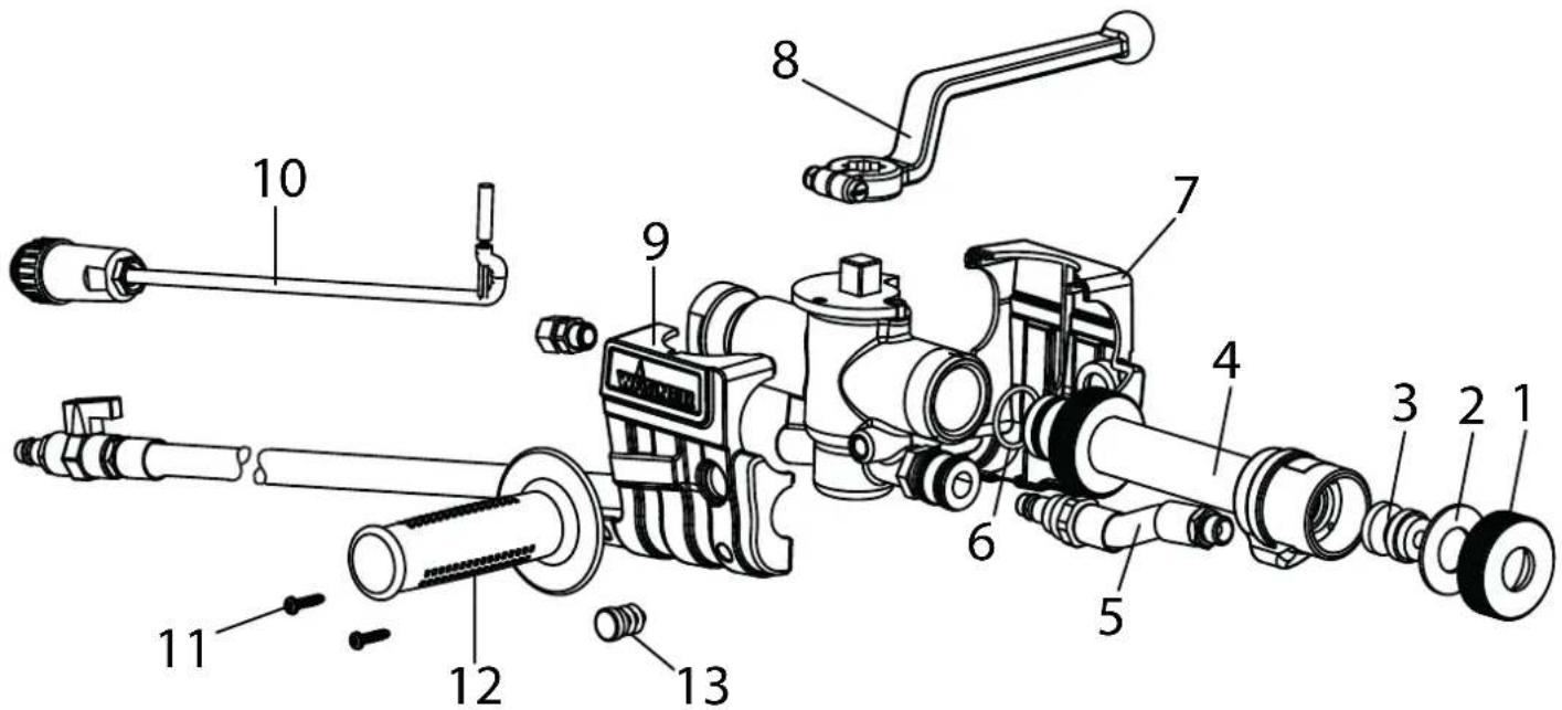
Technical diagram of a mechanical vehicle with numbered components for identification12 SPARE PARTS LIST - SPRAY LANCE
ITEM PART NO. DESIGNATION
| 2334 115 Automatic spray lance |
| 2322 199 Complete spray head (composed of positions 1-6) |
| 1 2321 045 Union nut |
| 2 0342 350 Sealing washer |
| 3 0268 781 Texture tip 8 (standard) |
| 6 2322 488 O-ring 25 x 2,5 |
ITEM PART NO. DESIGNATION
| 7 2323 764 Housing component, left |
| 8 2319 220 Lever |
| 9 2323 782 Housing component, right |
| 10 0348 216 Reed sensor, cpl. |
| 11 2336 554 Oval-head screw (2) |
| 12 2324 716 Hand-grip |
| 13 2336 221 Stoppers (2) |
text_image
Exploded view diagram of a mechanical device with numbered parts for identification13 PLASTCOAT 1030 ACCESSORIES
ITEM PART NO. DESIGNATION
1 2334 115 Automatic spray lance
2 2334 120 Ceiling spray lance (150 cm)
3 2334 121 Rendering lance
4 Texture tips for automatic spray lance and ceiling spray lance:
0268 779 Texture tip 4
0348 915 Texture tip 5
0268 780 Texture tip 6
0348 916 Texture tip 7
0268 781 Texture tip 8 (standard)
0348 917 Texture tip 9
0268 782 Texture tip 10
0342 327 Texture tip 12
0342 328 Texture tip 15
0268 905 Texture tip set 4, 6, 8, 10
5 2362 235 Rendering tip 10
2362 236 Rendering tip 12
0268 746 Rendering tip 14
0268 747 Rendering tip 16
0268 748 Rendering tip 18
0268 726 Rendering tip set 14, 16, 18
6 2334 123
80-cm extension
2339 400
150-cm extension
2334 124
200-cm extension
7 2335 394 Glue attachment
8 2335 388 Fill/dosing attachment
9 Mortar hose (including air hose and control cable) for automatic spray lance (2334115, 2334120, 2334121)
2334 131 Mortar hose DN 19 – 2 m, Connection V 27
0342 706 Mortar hose DN 19 – 10 m, Connection V 27
0348 930 Mortar hose DN 19 – 20 m, Connection V 27
0348 912 Mortar hose DN 27 – 10 m, Connection V 27
0348 946 Mortar hose DN 35 – 13,3 m, Connection V 27
ITEM PART NO. DESIGNATION
10 0342 314 Fix coupling seal M 27
11 2337 672 Angled spray head
12 0342 916 Cleaning needle
13 0342 330 Cleaning ball for DN 19 0342 331 Cleaning ball for DN 27 0342 332 Cleaning ball for DN 35
14 0342 329 Bottle brush for cleaning the inside of the outlet unit and spray lance
15 9992 824 Pump sliding means 500 ml
16 0342 215 Hose holder
17 0342 241 Cleaning adapter M 27 – GK 0348 948 Cleaning adapter M 35 – GK
18 2311 921 Compressor VKM 592, 230 V\~, 50 Hz, suction volume 590 l/min
19 2337 718 Compressor C330, 230 V\~, 50 Hz, suction volume 330 l/min
20 2311 692 Control cable for automatic spray lance 14 m (no picture)
21 2312 136 Lubricant for mortar hose (Metylan wallpaper paste) 125g (no picture)
PlastCoat 1030 Accessories illustration
text_image
Exploded view diagram of a mechanical device with numbered parts for identificationTESTING OF THE MORTAR SPRAYING MACHINE
For safety reasons, we would recommend having the device checked by an expert as required but at least every 12 months to ensure that it can continue to operate safely.
In the case of unused devices, the check can be postponed until they are next started up.
All (potentially deviating) national inspection and maintenance regulations must also be observed.
If you have any questions, please contact the customer service team at Wagner.
NOTE ON DISPOSAL
In accordance with European Directive 2012/19/EU on the disposal of waste electrical equipment and its implementation in national law, this product may not be disposed of with the household refuse, but must rather be recycled in an environmentally correct manner.
Your waste WAGNER device will be taken back by us or our representatives and disposed of environmentally correctly. Please contact one of our service points or one of our representatives or us directly to this purpose.
IMPORTANT INFORMATION ON PRODUCT LIABILITY
According to an EU directive, the manufacturer is only liable without limitation for faults in the product if all parts come from the manufacturer or have been approved by the manufacturer and have been mounted to the device and are operated properly. If third-party accessories or spare parts are used, the manufacturer is exonerated wholly or partly from his/her liability if use of the third-party accessories or spare parts have caused a defect in the product. In extreme cases, the relevant authorities can completely prohibit using the entire device.
With original WAGNER accessories and spare parts, compliance with all safety regulations is guaranteed.
GUARANTEE DECLARATION
(Status 01.02.2009)
1. Scope of guarantee
All Wagner professional colour application devices (hereafter referred to as products) are carefully inspected, tested and are subject to strict checks under Wagner quality assurance. Wagner exclusively issues extended guarantees to commercial or professional users (hereafter referred to as "customer") who have purchased the product in an authorised specialist shop, and which relate to the products listed for that customer on the Internet under www.wagner-group.com/profi-guarantee.
The buyer's claim for liability for defects from the purchase agreement with the seller as well as statutory rights are not impaired by this guarantee.
We provide a guarantee in that we decide whether to replace or repair the product or individual parts, or take the device back and reimburse the purchase price. The costs for materials and working hours are our responsibility. Replaced products or parts become our property.
2. Guarantee period and registration
The guarantee period amounts to 36 months. For industrial use or equal wear, such as shift operations in particular, or in the event of rentals it amounts to 12 months.
Systems driven by petrol or air are also guaranteed for a 12 month period.
The guarantee period begins with the day of delivery by the authorised specialist shop. The date on the original purchase document is authoritative.
For all products bought in authorised specialist shops from 01.02.2009 the guarantee period is extended to 24 months providing the buyer of these devices registers in accordance with the following conditions within 4 weeks of the day of delivery by the authorised specialist shop.
Registration can be completed on the Internet under www.wagner-group.com/profi-guarantee.
The guarantee certificate is valid as confirmation, as is the original purchase document that carries the date of the purchase. Registration is only possible if the buyer is in agreement with having the data being stored that is entered during registration.
When services are carried out under guarantee the guarantee period for the product is neither extended nor renewed.
Once the guarantee period has expired, claims made against the guarantee or from the guarantee can no longer be enforced.
3. Handling
If defects can be seen in the materials, processing or performance of the device during the guarantee period, guarantee claims must be made immediately, or at the latest within a period of 2 weeks.
The authorised specialist shop that delivered the device is entitled to accept guarantee claims. Guarantee claims may also be made to the service centres named in our operating instructions. The product has to be sent without charge or presented together with the original purchase document that includes details of the purchase date and the name of the product. In order to claim for an extension to the guarantee, the guarantee certificate must be included.
The costs as well as the risk of loss or damage to the product in transit or by the centre that accepts the guarantee claims or who delivers the repaired product, are the responsibility of the customer.
4. Exclusion of guarantee
Guarantee claims cannot be considered
-for parts that are subject to wear and tear due to use or other natural wear and tear, as well as defects in the product that are a result of natural wear and tear, or wear and tear due to use. This includes in particular cables, valves, packaging, jets, cylinders, pistons, means-carrying housing components, filters, pipes, seals, rotors, stators, etc. Damage due to wear and tear that is caused in particular by sanded coating materials, such as dispersions, plaster, putty, adhesives, glazes, quartz foundation.
-in the event of errors in devices that are due to non-compliance with the operating instructions, unsuitable or unprofessional use, incorrect assembly and/or commissioning by the buyer or by a third party, or utilisation other than is intended, abnormal ambient conditions, unsuitable coating materials, unsuitable operating conditions, operation with the incorrect mains voltage supply/frequency, over-operation or defective servicing or care and/or cleaning.
-for errors in the device that have been caused by using accessory parts, additional components or spare parts that are not original Wagner parts.
-for products to which modifications or additions have been carried out.
-for products where the serial number has been removed or is illegible
-for products to which attempts at repairs have been carried out by unauthorised persons.
-for products with slight deviations from the target properties, which are negligible with regard to the value and usability of the device.
-for products that have been partially or fully taken apart.
5. Additional regulations.
The above guarantees apply exclusively to products that have been bought by authorised specialist shops in the EU, CIS, Australia and are used within the reference country.
If the check shows that the case is not a guarantee case, repairs are carried out at the expense of the buyer.
The above regulations manage the legal relationship to us concludingly. Additional claims, in particular for damages and losses of any type, which occur as a result of the product or its use, are excluded from the product liability act except with regard to the area of application.
Claims for liability for defects to the specialist trader remain unaffected.
German law applies to this guarantee. The contractual language is German. In the event that the meaning of the German and a foreign text of this guarantee deviate from one another, the meaning of the German text has priority.
J. Wagner GmbH
Division Professional Finishing
Otto Lilienthal Strasse 18
88677 Markdorf
Federal Republic of Germany
Subject to modifications · Printed in Germany
EU Declaration of conformity
We declare under sole responsibility that this product conforms to the following relevant stipulations: 2006/42/EC, 2014/30/EU, 2011/65/EU, 2012/19/EU
Applied harmonised norms:
EN ISO 12100, EN 12001, EN 60204-1, EN 61000-3-2, EN 61000-3-3, EN 61000-6-1, EN 61000-6-3
The EU declaration of conformity is enclosed with the product. If required, it can be re-ordered using order number 2368963.
natural_image
Line drawing of a mechanical pump or launcher system on an inclined plane (no text or symbols)2 INTRODUCTION AU TRAVAIL AVEC LA MACHINE À PROJETER LE MORTIER PLASTCOAT1030
text_image
Technical diagram of a mechanical device with numbered parts labeled 9, 10, and 12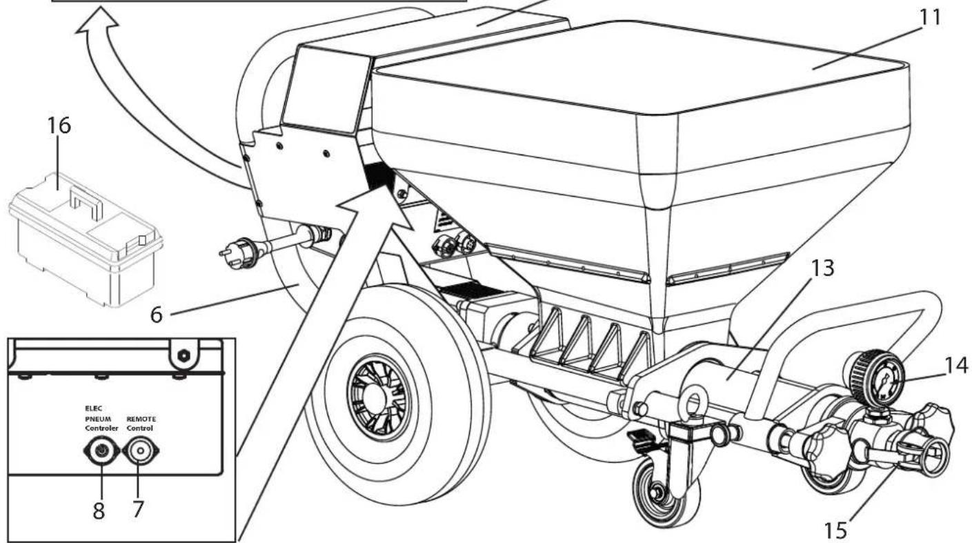
text_image
16 6 11 13 14 15 8 7 ELEC PNEUM Controller REMOTE Control4.1 ÉLÉMENTS DE COMMANDE ET AFFICHAGES SUR L'APPAREIL
natural_image
Technical line drawing of a pressure vessel with wheels and internal components (no text or symbols)natural_image
Technical line drawing of a mechanical device with internal components and wheels (no text or symbols)4.4 FLEXIBLE DE MORTIER
text_image
Technical diagram of a mechanical device with numbered components for identification5 TRANSPORT
5.1 ROULAGE
natural_image
Line drawing of a manual plow or seedling machine with a crane lifting a rectangular component (no text or symbols)5.3 TRANSPORT DANS LE VÉHICULE
text_image
Technical diagram of a manual pump assembly with numbered parts labeled 1 to 5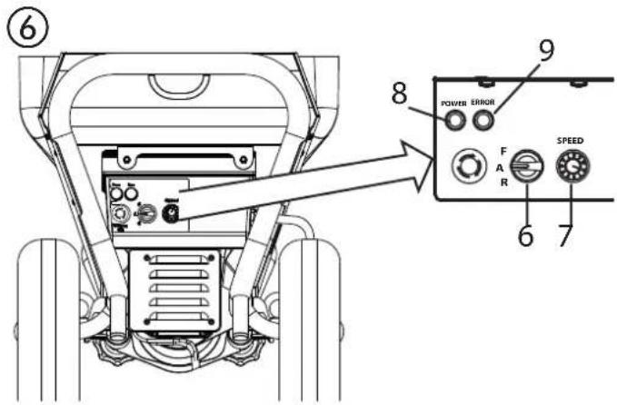
text_image
⑥ 8 POWER ERROR F A R SPEED 9 6 76.3 RACCORDER LE FLEXIBLE À MORTIER
text_image
Technical diagram of a mechanical device with labeled parts, showing fluid flow path and component connections.
text_image
WARTNER 2 3 1 ⑧
text_image
AGNER 9 46.6 RACCORDER LA LANCE DE PULVÉRISATION (FIG. 10)
text_image
Technical diagram of a mechanical device with numbered parts labeled 1 through 10
text_image
11 ELEC PNEUM Controller REMOTE Control⑫
text_image
Technical diagram of a vehicle rear panel with labeled components including buttons and indicators6.7.1 RINÇAGE PRÉALABLE DU FLEXIBLE À MORTIER
text_image
Technical diagram of a mechanical device with numbered parts and labeled control buttons including power, side, speed, and gear.Démontage
natural_image
Technical line drawing of a mechanical device with labeled parts (1 and 15), showing internal components without any readable text or symbols.9 MAINTENANCE

text_image
Technical diagram of a mechanical device with numbered parts and labeled control buttons including power switch, speed, and fan.9.5 REMPLACEMENT DU ROTOR (FIG. 17)
text_image
Technical diagram of a mechanical device with labeled parts 1 and 6, showing components like rollers, gears, and shafts.10 REMÈDE AUX PERTURBATIONS
text_image
Technical diagram of a mechanical device with numbered components for identification12 LISTE DES PIÈCES DE RECHANGE DE LA LANCE DE PROJECTION
POS. PRÉF. NO. DÉSIGNATION
text_image
Exploded view diagram of a mechanical assembly with numbered parts for identification13 ACCESSOIRES PLASTCOAT 1030
N°. RÉFÉRENCE DÉSIGNATION
text_image
Exploded view diagram of a mechanical device with numbered parts for identificationCONTRÔLE DE LA MACHINE À PROJETER LE MORTIER
INDICATION DE MISE AU REBUT
Division Professional Finishing
Otto Lilienthal Strasse 18
88677 Markdorf
natural_image
Technical line drawing of a mechanical device on an inclined plane, no text or symbols present2 INLEIDING TOT HET WERKEN MET DE MORTELSPUITMACHINE PLASTCOAT 1030
text_image
Technical diagram of a power pump system with labeled components and wiring details4.1 BEDIENINGSELEMENTEN EN WEERGAVEN OP HET APPARAAT
natural_image
Technical line drawing of a pressure vessel with internal components and wheels (no text or symbols)natural_image
Technical line drawing of a mechanical device with gears and housing (no text or symbols)4.4 MORTELSLANG
text_image
Technical diagram of a mechanical device with numbered components for identification5 TRANSPORT
5.1 VERRIJDEN
natural_image
Line drawing of a manual plow or seedling machine with a crane lifting a tray (no text or symbols)5.3 TRANSPORT IN EEN VOERTUIG
text_image
Technical diagram of a manual pump assembly with numbered parts labeled 1 to 5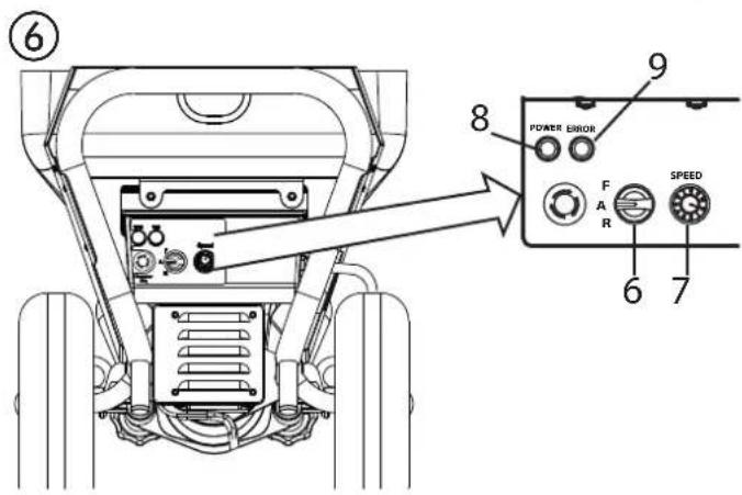
text_image
⑥ POWER ERROR F A R SPEED 6 7 8 9
text_image
Technical diagram of a mechanical device with labeled parts, showing hoses and tubing connections6.5 MONTAGE SPUITOPZETSTUKKEN (ACCESSOIRE)
text_image
Technical diagram of a mechanical device with numbered parts for identification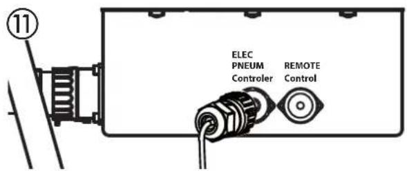
text_image
11 ELEC PNEUM Controller REMOTE Control6.7 MORTELSPUITMACHINE VOORBEREIDEN (AFB. 12)
text_image
Technical diagram of a mechanical device with numbered components and labeled parts including power motor, speed, and adjustment knobs.8.3 SPUITLANS REINIGEN
natural_image
Technical line drawing of a mechanical device with labeled parts (1 and 15), showing internal components without any readable text or symbols.9 ONDERHOUD

text_image
Technical diagram of a mechanical device with labeled parts 1 and 6, showing components like rollers, gears, and shafts.10 VERHELPEN VAN STORINGEN
text_image
Technical diagram of a manual pump system with numbered components for identification11.1 ONDERDELENLIJST ONDERSTEL
POS. BESTELNR. BENAMING
1 3142039 Ringmoer M12
2 3069013 Vierkante stop
3 2367604 Zwenkwiel
4 348349 Wiel
5 9994902 Wieldop
6 2309787 Beschermkap
text_image
Technical diagram of a mechanical device with numbered components for identification12 ONDERDELENLIJST SPUITLANS
POS. BESTELNR. BENAMING
2334 115 Automatische spuitlans
text_image
Exploded view diagram of a mechanical assembly with numbered parts for identification13 ACCESSOIRES PLASTCOAT 1030
POS. BESTELNR. BENAMING
1 2334 115 Automatische spuitlans
2 2334 120 Plafondspuitlans (150 cm)
3 2334 121 Gronderinglans
text_image
Exploded view diagram of a mechanical device with numbered parts for identificationINSPECTIE VAN DE MORTELSPUITMACHINE
Division Professional Finishing
Otto Lilienthal Strasse 18
88677 Markdorf