HeavyCoat 750 G - Paint spray WAGNER - Free user manual and instructions
Find the device manual for free HeavyCoat 750 G WAGNER in PDF.
Download the instructions for your Paint spray in PDF format for free! Find your manual HeavyCoat 750 G - WAGNER and take your electronic device back in hand. On this page are published all the documents necessary for the use of your device. HeavyCoat 750 G by WAGNER.
USER MANUAL HeavyCoat 750 G WAGNER
Attention: Danger of injury by injection! Airless units develop extremely high spraying pressures.


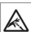
Never put your fingers, hands or any other parts of the body into the spray jet!
Never point the spray gun at yourself, other persons or animals.
Never use the spray gun without safety guard.
Do not treat a spraying injury as a harmless cut. In case of injury to the skin through coating materials or solvents, consult a doctor immediately for quick and expert treatment. Inform the doctor about the coating material or solvent used.

The operating instructions state that the following points must always be observed before starting up:
- Faulty units must not be used.
- Secure Wagner spray gun using the trigger lock on the trigger.
- Ensure that the unit is properly earthed.
- Check allowable operating pressure of high-pressure hose and spray gun.
- Check all connections for leaks.

The instructions regarding regular cleaning and maintenance of the unit must be strictly observed.
Before any work is done on the unit or for every break in work the following rules must be observed:
- Release the pressure from spray gun and hose.
- Secure the Wagner spray gun using the trigger lock on the trigger.
- Switch off unit.
Be safety conscious!
HeavyCoat
1 SAFETY REGULATIONS FOR AIRLESS SPRAYING 4
1.1 Explanation of symbols used 4
1.2 Safety hazards
1.3 Setup on an uneven surface 6
1.4 Electrical safety 6
1.5 Gasoline engine safety 6
1.6 Fueling (gas engine) 7
2 MAIN AREAS OF APPLICATION 8
2.1 Application 8
2.2 Coating materials 8
8 TROUBLESHOOTING 27
8.1 Airless gun 27
8.2 Fluid section 27
8.3 Hydraulic motors 28
8.4 Spray patterns 29
9 APPENDIX 30
9.1 Selection of tip 30
9.2 Servicing and cleaning of Airless hard-metal tips 30
9.3 2Speed Tip table 31
9.4 Airless tip table 32
IMPORTANT NOTES ON PRODUCT LIABILITY 34
3+2 YEARS GUARANTEE FOR PROFESSIONAL FINISHING 34
ACCESSIONS AND SPARE PARTS 104
Spare parts list for the main assembly 104
Spare parts list for the cart assembly 106
Spare parts list for the shovel valve HC 750 SSP 107
Spare parts list for the fluid section HC 730/750 108
Spare parts list for the fluid section HC 750/770 110
Spare parts list for the high-pressure filter 112
CONNECTION DIAGRAM (110V / 230V) 114
CONNECTION DIAGRAM (GAS ENGINE) 115
HYDRAULIC DIAGRAM 116
ACCESSIONS FOR HC UNITS I 117
ACCESSIONS FOR HC UNITS II 118
SALES AND SERVICE COMPANIES 124
3 DESCRIPTION OF UNIT 9
3.1 Airless process
3.2 Functioning of the unit 9
3.3 System diagram - gasoline HeavyCoat units 10
3.4 System diagram - electric HeavyCoat units 11
3.5 Technical data for HeavyCoat units 12
3.6 Transportation 13
3.7 Crane transport
4 OPERATION 13
4.1 Setup 13
4.2 Starting the engine (gas models) 15
4.3 Preparing a new sprayer 15
4.4 Preparing to paint 16
4.5 Painting 17
4.6 Pressure relief procedure 17
5 SPRAYING 18
5.1 Cleaning a clogged tip 18
5.2 Interruption of work 19
5.3 Handling the high pressure hose 19
6 CLEANUP 20
6.1 Special cleanup instructions for use with flammable solvents 20
6.2 Cleaning the sprayer 20
6.3 Cleaning the outside of the sprayer 20
6.4 Cleaning the filter screen 21
6.5 Cleaning the airless spray gun 21
7 MAINTENANCE 22
7.1 Daily maintenance 22
7.2 Lubricating the upper packings 22
7.3 Maintaining the filter assembly 22
7.4 Maintaining the hydraulic system 23
7.5 Maintaining the fluid section 24
7.6 High pressure hose 24
7.7 Basic engine maintenance 24
7.8 Servicing the fluid section 25
1 SAFETY REGULATIONS FOR AIRLESS SPRAYING
1.1 EXPLANATION OF SYMBOLS USED
This manual contains information that must be read and understood before using the equipment. When you come to an area that has one of the following symbols, pay particular attention and make certain to heed the safeguard.

This symbol indicates a potential hazard that may cause serious injury or loss of life. Important safety information will follow.

This symbol indicates a potential hazard to you or to the equipment. Important information that tells how to prevent damage to the equipment or how to avoid causes of minor injuries will follow.

Danger of skin injection

Danger of fire from solvent and paint fumes

Danger of explosion from solvent, paint fumes and incompatible materials

Danger of injury from inhalation of harmful vapors

Danger of injury from electric shock

Notes give important information which should be given special attention.
1.2 SAFETY HAZARDS

HAZARD: INJECTION INJURY
A high pressure stream produced by this equipment can pierce the skin and underlying tissues, leading to serious injury and possible amputation.
Do not treat a spraying injury as a harmless cut. In case of injury to the skin through coating materials or solvents, consult a doctor immediately for quick and expert treatment. Inform the doctor about the coating material or solvent used.
PREVENTION:
- NEVER aim the gun at any part of the body.
- NEVER allow any part of the body to touch the fluid stream. DO NOT allow body to touch a leak in the fluid hose.
- NEVER put your hand in front of the gun. Gloves will not provide protection against an injection injury.
- ALWAYS lock the gun trigger, shut the fluid pump off and release all pressure before servicing, cleaning the tip guard, changing tips, or leaving unattended. Pressure will not be released by turning off the engine. The PRIME/SPRAY valve or pressure bleed valve must be turned to their appropriate positions to relieve system pressure.
- ALWAYS keep tip guard in place while spraying. The tip guard provides some protection but is mainly a warning device.
- ALWAYS remove the spray tip before flushing or cleaning the system.
- NEVER use a spray gun without a working trigger lock and trigger guard in place.
- All accessories must be rated at or above the maximum operating pressure range of the sprayer. This includes spray tips, guns, extensions, and hose.

HAZARD: HIGH PRESSURE HOSE
The paint hose can develop leaks from wear, kinking and abuse. A leak can inject material into the skin. Inspect the hose before each use.
PREVENTION:
- Avoid sharp bending or kinking of the high-pressure hose. The smallest bending radius amounts to about 20cm .
- Do not drive over the high-pressure hose. Protect against sharp objects and edges.
- Replace any damaged high-pressure hose immediately.
- Never repair damaged high-pressure hoses yourself!
- Electrostatic charging of spray guns and the high-pressure hose is discharged through the high-pressure hose. For this reason the electric resistance between the connections of the high-pressure hose must be equal to or lower than 1M
- For reasons of function, safety and durability use only original Wagner high-pressure hoses.
- Before each use, check all hoses for cuts, leaks, abrasion or bulging of cover. Check for damage or movement of couplings. Immediately replace the hose if any of these conditions exist. Never repair a paint hose. Replace it with another earthed high-pressure hose.
- Make sure power cord, air hose and spray hoses are routed in such a manner to minimize slip, trip and fall hazard.
HAZARD: EXPLOSION OR FIRE
Flammable vapors, such as solvent and paint vapors, in work area can ignite or explode.
PREVENTION:
- Use equipment only in well ventilated area. Keep a good supply of fresh air moving through the area to keep the air within the spray area free from accumulation of flammable vapors. Keep pump assembly in well ventilated area. Do not spray pump assembly.
- Electric models only - Do not use materials with a flashpoint below 21^ C. Flashpoint is the temperature at which a fluid can produce enough vapors to ignite.
- Gas models only - Do not fill fuel tank while engine is running or hot; shut off engine and allow to cool. Fuel is flammable and can ignite or explode if spilled on a hot surface.
- Eliminate all ignition sources, such as pilot lights, cigarettes, portable electric lamps and plastic drop cloths (potential static arc).
- Keep work area free of debris, including solvent, rags and gasoline.
- Do not plug or unplug power cords, or turn power or light switches on or off when flammable vapors are present.
- Ground equipment and conductive objects in work area. Make sure the grounding cable (not equipped) is connected from the grounding lug to a true earth ground.
- Use only grounded hoses.
- Hold spray gun firmly to the side of a grounded pail when triggering into pail.
- If there is static sparking or if you feel a shock, stop operation immediately.
- Know the contents of the paint and solvents being sprayed. Read all material Safety Data Sheets (SDS) and container labels provided with the paints and solvents. Follow the paint and solvent manufacturer's safety instructions.
- Do not use a paint or solvent containing halogenated hydrocarbons. Such as chlorine, bleach, mildewcide, methylene chloride and trichloroethane. They are not compatible with aluminum. Contact the coating supplier about compatibility of material with aluminum.
- Keep a fire extinguisher in work area.

HAZARD: HAZARDOUS VAPORS
Paints, solvents, and other materials can be harmful if inhaled or come in contact with body. Vapors can cause severe nausea, fainting, or poisoning.
PREVENTION:
- Wear respiratory protection when spraying. Read all instructions supplied with the mask to be sure it will provide the necessary protection.
- All local regulations regarding protection against hazardous vapors must be observed.
- Wear protective eyewear.
- Protective clothing, gloves and possibly skin protection cream are necessary for the protection of the skin. Observe the regulations of the manufacturer concerning coating materials, solvents and cleaning agents in preparation, processing and cleaning units.

HAZARD:GENERAL
This product can cause severe injury or property damage.
PREVENTION:
- Follow all appropriate local, state, and national codes governing ventilation, fire prevention, and operation.
- Pulling the trigger causes a recoil force to the hand that is holding the spray gun. The recoil force of the spray gun is particularly powerful when the tip has been removed and high pressure has been set on the airless pump. When cleaning without a spray tip, set the pressure control knob to the lowest pressure.
- Use only manufacturer authorized parts. User assumes all risks and liabilities when using parts that do not meet the minimum specifications and safety devices of the pump manufacturer.
- ALWAYS follow the material manufacturer's instructions for safe handling of paint and solvents.
- Clean up all material and solvent spills immediately to prevent slip hazard.
- Wear ear protection. This unit can produce noise levels above 85 dB(A).
- Never leave this equipment unattended. Keep away from children or anyone not familiar with the operation of airless equipment.
- Do not spray on windy days.
- The device and all related liquids (i.e. hydraulic oil) must be disposed of in an environmentally friendly way.
1.3 SETUP ON AN UNEVEN SURFACE
The front end must always point downwards in order to avoid sliding away.
If possible do not use the unit on an inclined surface since the unit tends to wander due to the resulting vibrations.
1.4 ELECTRIC SAFETY
Electric models must be grounded/earthed. In the event of an electrical short circuit, grounding/earthing reduces the risk of electric shock by providing an escape wire for the electric current. This product is equipped with a cord having an grounding/earthing wire with an appropriate grounding/earthing plug. Connection to the power cord only through a special feed point, e.g. through an error protection installation with INF < 30mA .
|  | DANGER — Work or repairs at the electrical equipment may only be carried out by a skilled electrician. No liability is assumed for incorrect installation. Switch the unit off. Before all repair work, unplug the power plug from the outlet. |
|  | Danger of short-circuits caused by water ingressing into the electrical equipment. Never spray down the unit with high-pressure or high- pressure steam cleaners. |
1.5 GASOLINE ENGINE SAFETY
- Gas engines are designed to give safe and dependable service if operated according to instructions. Read and understand the engine manufacturer's Owner's Manual before operating the engine. Failure to do so could result in personal injury or equipment damage.
-
To prevent fire hazards and to provide adequate ventilation, keep the engine at least 1 meter (3 feet) away from buildings and other equipment during operation. Do not place flammable objects close to the engine.
-
People who are not operating the device must stay away from the area of operation due to a possibility of burns from hot engine components or injury from any equipment the engine may be used to operate.
- Know how to stop the engine quickly, and understand the operation of all controls. Never permit anyone to operate the engine without proper instructions.
- Gasoline is extremely flammable and is explosive under certain conditions.
- Refuel in a well-ventilated area with the engine stopped. Do not smoke or allow flames or sparks in the refueling area or where gasoline is stored.
- Do not overfill the fuel tank. After refueling, make sure the tank cap is closed properly and securely.
- Be careful not to spill fuel when refueling. Fuel vapor or spilled fuel may ignite. If any fuel is spilled, make sure the area is dry before starting the engine.
- Never run the engine in an enclosed or confined area. Exhaust contains poisonous carbon monoxide gas; exposure may cause loss of consciousness and may lead to death.
- The muffler becomes very hot during operation and remains hot for a while after stopping the engine. Be careful not to touch the muffler while it is hot. To avoid severe burns or fire hazards, let the engine cool before transporting it or storing it indoors.
- Never ship/transport sprayer with gasoline in the tank.

DO NOT use this equipment to spray water or acid.
1.6 FUELING (GAS ENGINE)

Gasoline is extremely flammable and is explosive under certain conditions.
FUEL SPECIFICATIONS
Use automotive gasoline that has a pump octane number of 86 or higher, or that has a research octane number of 91 or higher. Use of a lower octane gasoline can cause persistent "pinging" or heavy "spark knock" (a metallic rapping noise) which, if severe, can lead to engine damage.

If "spark knock" or "pinging" occurs at a steady engine speed under normal load, change brands of gasoline. If spark knock or pinging persists, consult an authorized dealer of the engine manufacturer. Failure to do so is considered misuse, and damage caused by misuse is not covered by the engine manufacturer's limited warranty.
Occasionally you may experience light spark knock while operating under heavy loads. This is no cause for concern, it simply means your engine is operating efficiently.
- Unleaded fuel produces fewer engine and spark plug deposits and extends the life of the exhaust system components.
- Never use stale or contaminated gasoline or an oil/gasoline mixture. Avoid getting dirt, dust, or water in the fuel tank.
GASOLINES CONTAINING ALCOHOL
If you decide to use a gasoline containing alcohol (gasohol), be sure its octane rating is at least as high as that recommended by the engine manufacturer. There are two types of "gasohol": one containing ethanol, and the other containing methanol. Do not use gasohol that contains more than 10% ethanol. Do not use gasoline containing methanol (methyl or wood alcohol) that does not also contain co-solvents and corrosion inhibitors for methanol. Never use gasoline containing more than 5% methanol, even if it has co-solvents and corrosion inhibitors.

Fuel system damage or engine performance problems resulting from the use of fuels that contain alcohol is not covered under the warranty. The engine manufacturer cannot endorse the use of fuels containing methanol since evidence of their suitability is incomplete at this time.
Before buying gasoline from an unfamiliar station, try to find out if the gasoline contains alcohol. If it does, confirm the type and percentage of alcohol used. If you notice any undesirable operating characteristics while using a gasoline that contains alcohol, or one that you think contains alcohol, switch to a gasoline that you know does not contain alcohol.
2 MAIN AREAS OF APPLICATION
2.1 APPLICATION
The main area of application are thick layers of highly viscous coating material for large areas and a high consumption of material.
Priming and final coating of large areas, sealing, impregnation, construction sanitation, façade protection and renovation, rust protection and building protection, roof coating, roof sealing, concrete sanitation, as well as heavy corrosion protection.
EXAMPLES OF OBJECTS TO BE SPRAYED
Large-scale construction sites, cooling towers, bridges, sewage treatment plants and terraces.
This equipment will operate correctly in its intended ambient, at a minimum between +10^ and +40^ .
RELATIVE HUMIDITY
The equipment will operate correctly within an environment at 50% RH, +40^ . Higher RH may be allowed at lower temperatures.
Measures shall be taken by the Purchaser to avoid the harmful effects of occasional condensation.
ALTITUDE
This equipment will operate correctly up to 2100m above mean sea level.
TRANSPORTATION AND STORAGE
This equipment will withstand, or has been protected against, transportation and storage temperatures of -25^ to +55^ and for short periods up to +70^ .
It has been packaged to prevent damage from the effects of normal humidity, vibration and shock.
RECOMMENDED HOSE CONFIGURATION

Use only Wagner original-high-pressure hoses in order to ensure functionality, safety and durability.
2.2 COATING MATERIALS
PROCESSIBLE COATING MATERIALS
Diluting lacquers and paints or those containing solvents, two-component coating materials, dispersion and latex paints.
No other materials should be used for spraying without Wagner's approval.

Pay attention to the Airless quality of the coating materials to be processed.
VISCOSITY
The unit is able to process coating materials with up to 50.000 / 65.000 mPas. If highly viscous coating materials cannot be taken in or the performance of the unit is to low, the paint must be diluted in accordance with the manufacturer's instructions.

Attention: Make sure, when stirring up with motor-driven agitators that no air bubbles are stirred in. Air bubbles disturb when spraying and can, in fact, lead to interruption of operation.
COATING MATERIALS WITH ABRASIVE MATERIALS
These particles have a strong wear and tear effect on valves and tips, but also on the spray gun. This impairs the durability of these wearing parts considerably.
TWO-COMPONENT COATING MATERIAL
The appropriate processing time must be adhered to exactly. Within this time rinse through and clean the unit meticulously with the appropriate cleaning agents.
FILTERING
Sufficient filtering is required for fault-free operation. The unit is equipped with a suction filter, an insertion filter in the spray gun and a high pressure filter on the unit. Regular inspection of these filters for damage or soiling is urgently recommended. If using this sprayer with textured materials, it is important that the filter inside of the spray gun be removed. See section 6.5.
3 DESCRIPTION OF UNIT
3.1 AIRLESS PROCESS
A piston pump takes in the coating material by suction and conveys it to the tip. Pressed through the tip at a pressure of up to a maximum of 3600 PSI (250 bar, 25 MPa), the coating material is atomised. This high pressure has the effect of micro fine atomization of the coating material.
As no air is used in this process, it is described as an AIRLESS process.
This method of spraying has the advantages of finest atomization, cloudless operation and a smooth, bubble-free surface. As well as these, the advantages of the speed of work and convenience must be mentioned.
3.2 FUNCTIONING OF THE UNIT
The following section contains a brief description of the technical construction for better understanding of the function of the unit.

This manual gives information for both electric motor and gasoline engine HeavyCoat models.
Wagner HeavyCoat are high-pressure spraying units driven by either a gasoline engine or electric motor.
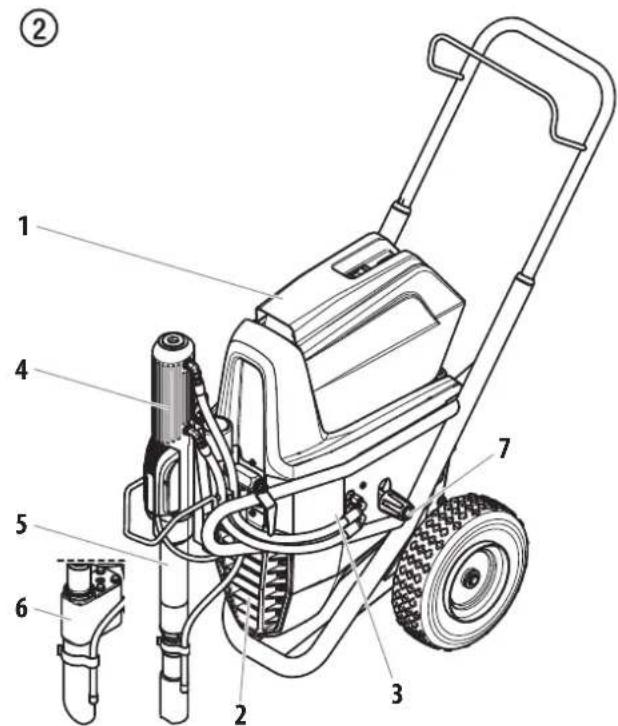
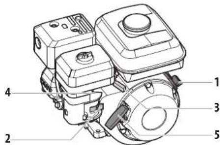
The gasoline engine or electric motor (fig. 2, item 1) drives the hydraulic pump (3) by means of a V-belt which is under the belt cover (2). Hydraulic oil flows to the hydraulic motor (4) and then moves the piston up and down in the material feed pump (5).
With device HC 750 SSP the piston in the material feed pump moves a shovel valve (6). The shovel valve feeds high-viscosity coating materials.
The inlet valve is opened automatically by the upwards movement of the piston. The outlet valve is opened when the piston moves downward.
The coating material flows under high pressure through the high-pressure hose to the spray gun. When the coating material exits from the tip it atomizes.
The pressure control valve (7) controls the volume and the operating pressure of the coating material.
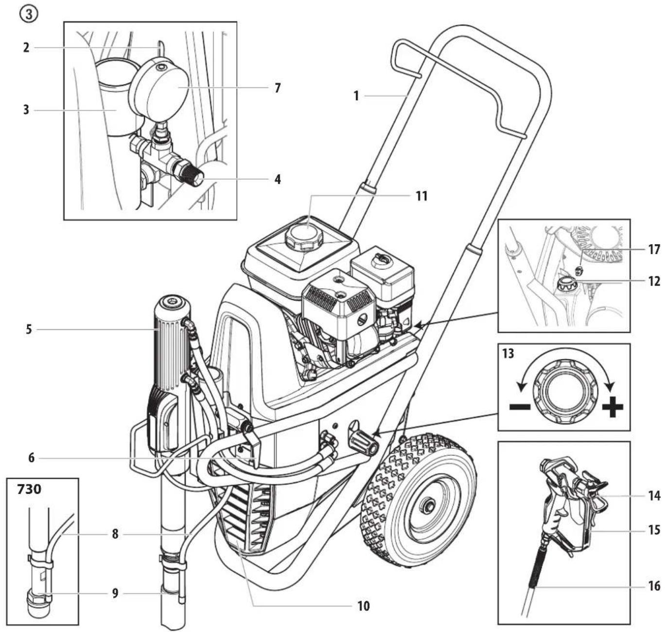
3.3 SYSTEM DIAGRAM - GASOLINE HEAVYCOAT UNITS
- Extractable handle
- Oil cup for separating oil (separating oil prevents increased wear and tear of the packings)
- High-pressure filter
- High-pressure hose outlet
-
Hydraulic motor
-
Relief valve handle:
Turn left for circulation
Turn right for spray - Manometer
- Bleed hose
- Suction tube
-
V-belt under the belt cover
-
Gasoline engine
- Oil measuring stick
- Pressure control knob
- Tip guard with airless tip
- Spray gun
- High-pressure hose
- Grounding lug
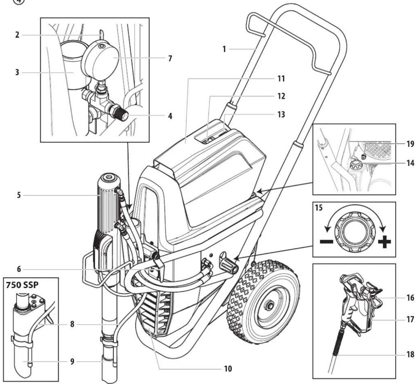
3.4 SYSTEM DIAGRAM - ELECTRIC HEAVYCOAT UNITS
- Extractable handle
- Oil cup for separating oil (separating oil prevents increased wear and tear of the packings)
- High-pressure filter
- High-pressure hose outlet
-
Hydraulic motor
-
Relief valve handle:
Turn left for circula
Turn right for spray

- Manometer
- Bleed hose
- Suction tube
- V-belt under the belt cover
- Electric motor
-
ON/OFF swtich
-
Control lamp that shows unit operational
- Oil measuring stick
- Pressure control knob
- Tip guard with airless tip
- Spray gun
- High-pressure hose
- Grounding lug
(4)
3.5 TECHNICAL DATA
| HeavyCoat 730 (gas) H | HeavyCoat 750 (110V) HeavyCoat 750 (230V) | HeavyCoat 750 SSP (230V) | HeavyCoat 750 (gas) H | HeavyCoat 770 (gas) | |
| Gasoline engine, power | |||||
| Honda | 63cc, 4.9 Hp, 3.6 kW | 196cc, 5.6 Hp, 4.1 kW | 270cc, 8.4 Hp, 6.2 kW | ||
| Fuel Capacity | |||||
| 3.1 I | 3.1 I 6.06 I | ||||
| Voltage | |||||
| 110V | - | ~ 110V, 50 Hz | - | - | - |
| 230V | - | ~ 230V, 50/60 Hz | ~ 230V, 50/60 Hz | ||
| Capacity | |||||
| - | 3.1 kW 3.1 kW | - | |||
| Power Cord | |||||
| - | 3 x 2.5 mm² - 6 m 3 x 2.5 mm² - 6 m | - | |||
| Current Protection | |||||
| - | 15 A 15 A | - | |||
| Max. operating pressure | |||||
| 25 MPa (250 bar) 25 MPa (250 bar) 25 MPa (250 bar) 25 MPa (250 bar) 25 MPa (250 bar) | |||||
| Max. sound pressure level | |||||
| 92 dB (A)* 80 dB (A)* 80 dB (A)* 92 dB (A)* 98 dB (A)* | |||||
| Max. size of tip with a spray gun | |||||
| 1-gun | 0.041" - 1.04 mm | 0.043" - 1.09 mm | 0.043" - 1.09 mm | 0.047" - 1.19 mm | 0.055" - 1.40 mm |
| 2-gun | 0.029" - 0.73 mm | 0.031" - 0.79 mm | 0.031" - 0.79 mm | 0.033" - 0.84 mm | 0.039" - 0.99 mm |
| 3-gun | 0.021" - 0.53 mm | 0.023" - 0.58 mm | 0.023" - 0.58 mm | 0.027" - 0.68 mm | 0.031" - 0.79 mm |
| 4-gun | 0.019" - 0.48 mm | 0.021" - 0.53 mm | 0.021" - 0.53 mm | 0.023" - 0.58 mm | 0.027" - 0.68 mm |
| Max. volume flow | |||||
| 6.00 l/min 6.00 l/min in 6.00 l/min 7.60 l/min | 11.4 l/min | ||||
| Weight | |||||
| 78 kg | 85 kg | 87 kg | 81 kg | 90 kg | |
| Suction system | |||||
| standard | submersible | shovel valve | submersible | submersible | |
| Max. viscosity | |||||
| 50.000 mPa·s | 65.000 mPa·s | ||||
| Dimensions L x W x H | |||||
| 1090 x 660 x 866 mm | |||||
| Max. temperature of the coating material | |||||
| 43°C | |||||
| Filter insert (standard equipment) | |||||
| 50 mesh, 18 in² | 0 mesh, 18 in² | 50 mesh, 18 in² | 50 mesh, 18 in² | 5 mesh, 18 in² | |
| Hydraulic oil filling quantity | |||||
| 5.9 I | |||||
| Max. tire pressure | |||||
| 0.2 MPa (2 bar, 30 PSI) | |||||
| Recommended hose configuration | |||||
| DN 12 mm, 15 m, connection thread NPSM 1/2, DN 6 mm, 60 m, connection thread NPSM 1/4 | |||||
- Place of measurement: 1 m distance from unit and 1.60 m above reverberant floor, 120 bar (12 MPa) operating pressure.
3.6 TRANSPORTATION

Do not lift by cart handle when loading or unloading. Device is very heavy. Three-person lift is required.
TRANSPORTATION IN VEHICLE
Secure the unit with a suitable fastening.
PUSHING OR PULLING THE UNIT
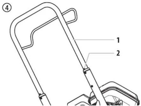
Pull out the handle (Fig. 4, Item 1) until it will come no further. Insert the handle - push the buttons (2) on the cart, and then push in the handle.
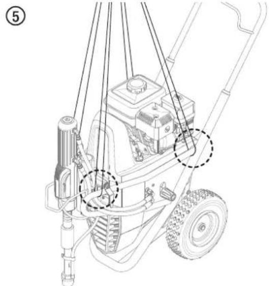
3.7 CRANE TRANSPORT
Hanging points for crane straps or ropes, see figure 5.
4 OPERATION
|  | This equipment produces a fluid stream at extremely high pressure. Read and understand the warnings in the Safety Precautions section at the front of this manual before operating this equipment. |
4.1 SETUP
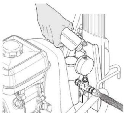
-
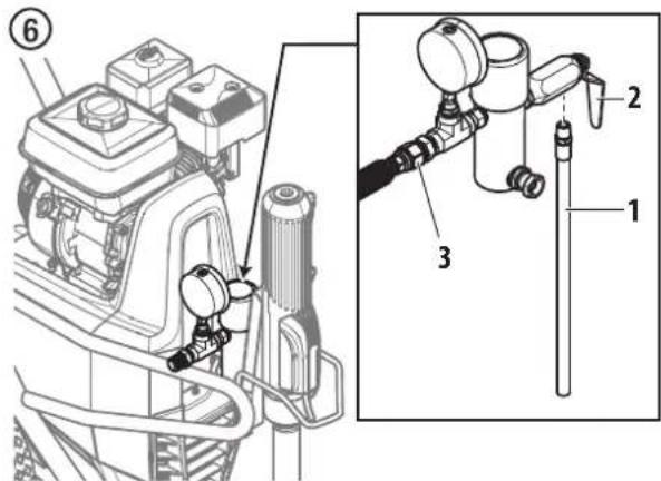
Make sure the bleed hose (Fig. 6, item 1) is threaded into the bleed valve (2). It has factory installed PTFE tape on the fitting and should be tightened wrench tight.
-
Attach a minimum of 50^ (15 m) of nylon airless spray hose (3) to the sprayer. Do not use PTFE tape or thread sealant on the spray hose connection.
- Attach an airless spray gun to the spray hose. Do not attach the tip to the spray gun yet. Remove the tip if it is already attached.
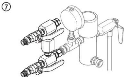
| i | For multiple gun operation, connect a multiple gun manifold to the single gun outlet. Connect a hose and gun to each outlet. Make sure the second gun outlet remains plugged. See "Technical Data", Section 3.5 to determine number of guns and maximum spray tip sizes. |
- Fill the oil cup 1/2 full with EasyGlide (P/N 0508619). This extends packing life.
⑧
- Check the hydraulic fluid level daily before starting the sprayer. The hydraulic fluid level should be touching the bottom of the dipstick. Refer to the Maintenance section of this manual for hydraulic system maintenance instructions.
- For gas models, check the engine oil level daily before starting the sprayer. The gasoline engine oil level is determined by the engine manufacturer. Refer to the engine manufacturer's service manual supplied with this sprayer.
- For electric models, use a 15 amp service outlet. Always locate the electric model within 10 to 15 feet of the service outlet. Use a short electric cable and a long paint hose. Any extension cord will create some voltage drop. If an extension cord is necessary, use only a grounded 3-wire 12-gauge extension cord.
- Make sure the sprayer is grounded/earthy. All sprayers are equipped with a grounding/earthing lug. A grounding/earthing cable should be used to connect the sprayer to a true earth ground. Check your local electrical regulations for detailed grounding/earthing instructions.

Proper grounding/earthing is important. The passage of some materials through the nylon fluid hose will build up a static electric charge, which if discharged, could ignite solvent vapors present and create an explosion.
- Strain all paints with a nylon strainer to ensure trouble free operation and freedom from frequent cleaning of the suction filter and gun filter.
- Make sure the spray area is well ventilated to prevent hazardous operation with volatile solvents or exhaust fumes.

If lacquer or other flammable materials are to be sprayed, ALWAYS locate the sprayer outside the immediate spraying area. Failure to do so may cause an explosion.
- Locate the sprayer outside the immediate spraying area to avoid clogged air intake of the engine with overspray.
4.2 STARTING THE ENGINE (GAS MODELS)

Follow these instructions whenever prompted in this manual to start the engine.
- Move the fuel valve lever (Fig. 9, item 2) to the open position.
- Move the throttle lever (3) to its middle point.
- Move the choke lever (4) to the closed position for a cold engine or to the open position for a warm engine.
- Turn the engine switch (1) to the ON position.
- Pull the starter rope (5) briskly until the engine starts.
⑨

If choke lever (4) was moved to closed position to start the engine, it must be opened again once the engine is running.
4.3 PREPARING A NEW SPRAYER
| i | If this unit is new, it is shipped with test fluid in the fluid section to prevent corrosion during shipment and storage. This fluid must be thoroughly cleaned out of the system with suitable cleaning agent before you begin spraying. |
| !Attention | Always keep the trigger lock on the spray gun in the locked position while preparing the system. Refer to the spray gun instruction manual for trigger lock instructions. |
- Place the siphon tube into a container of suitable cleaning agent.
-
Place the bleed hose into a metal waste container.
-
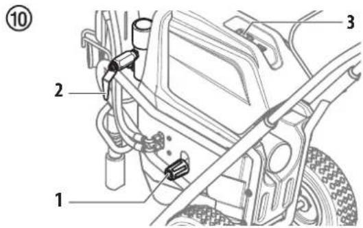
Turn the pressure control knob fully counterclockwise to its lowest pressure setting (Fig. 10, item 1).
- Open the bleed valve (2) by turning it fully counterclockwise.
- Start the engine or turn on the electric motor:
a. To start the gas engine, follow the steps in section 4.2.
b. To start the electric motor, push and hold the ON/OFF switch (3) in the ON position until the electric motor is at full speed, then release the switch.
- Turn the pressure control knob (fig. 10, item 1) clockwise approximately 1/3 of the way to increase pressure until the sprayer cycles evenly and solvent flows freely from the bleed hose.
-
Allow the sprayer to run for 15-30 seconds to flush the test fluid out through the bleed hose and into the waste container.
-
Turn off the sprayer.
a. To turn off the gas engine,
- set the pressure to minimum by turning the pressure control knob fully counterclockwise,
- move the throttle lever to the slow position, and
- turn the engine switch to the OFF position.
b. To turn off the electric motor,
- set the pressure to minimum by turning the pressure control knob fully counterclockwise,
- move the ON/OFF switch to the OFF position.
4.4 PREPARING TO PAINT
| i | Before painting, it is important to make sure that the fluid in the system is compatible with the paint that is going to be used. Incompatible fluids and paint may cause the valves to become stuck closed, which would require disassembly and cleaning of the sprayer's fluid section. |
| !Attention | Always keep the trigger lock on the spray gun in the locked position while preparing the system. Refer to the spray gun instruction manual for trigger lock instructions. |
- Place the siphon tube into a container of mineral spirits.
- Place the bleed hose into a metal waste container.
- Turn the pressure control knob fully counterclockwise to its lowest pressure setting (Fig. 10, item 1).
- Open the bleed valve (2) by turning it fully counterclockwise.

- Start the engine or turn on the electric motor:
a. To start the gas engine, follow the steps in section 4.2
b. To start the electric motor, push and hold the ON/OFF switch (3) in the ON position until the electric motor is at full speed, then release the switch. - Turn the pressure control knob (Fig. 10, item 1) clockwise approximately 1/3 of the way to increase pressure until the sprayer cycles evenly and solvent flows freely from the bleed hose.
- Allow the sprayer to run for 15-30 seconds to flush the test fluid out through the bleed hose and into the waste container.
- Turn off the sprayer.
a. To turn off the gas engine, - set the pressure to minimum by turning the pressure control knob fully counterclockwise,
- move the throttle lever to the slow position, and
- turn the engine switch to the OFF position.
b. To turn off the electric motor,
- set the pressure to minimum by turning the pressure control knob fully counterclockwise,
- move the ON/OFF switch to the OFF position.

Make sure that the spray gun does not have a tip or tip guard installed.
- Close the bleed valve by turning it fully clockwise.
- Start the engine or turn on the electric motor.
- Turn the pressure control knob clockwise approximately 1/3 of the way down to increase pressure.
- Unlock the gun by turning the gun trigger lock to the unlocked position.
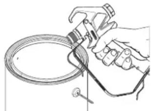
| Ground/Earth the gun by holding it against the edge of the metal container while flushing. Failure to do so may lead to a static electric discharge, which may cause a fire. |

- Trigger the gun into the metal waste container until the old solvent is gone and fresh solvent is coming out of the gun.
- Lock the gun by turning the gun trigger lock to the locked position (refer to spray gun manual).
- Set down the gun and increase the pressure by turning the pressure control knob slowly clockwise to its highest setting.
- Check the entire system for leaks. If leaks occur, turn the sprayer off and follow the "Pressure Relief Procedure" in this manual before tightening any fittings or hoses.
- Follow the "Pressure Relief Procedure" (section 4.6) in this manual before changing from solvent to paint.
| ! | Be sure to follow the Pressure Relief Procedure when shutting the unit down for any purpose, including servicing or adjusting any part of the spray system, changing or cleaning spray nozzles, or preparing for cleanup. |
4.5 PAINTING
- Place the siphon hose into a container of paint.
- Place the bleed hose into a metal waste container.
- Turn the pressure control knob fully counterclockwise to its lowest pressure setting (Fig. 10, item 1).
- Open the bleed valve (2) by turning it fully counterclockwise.
- Start the engine or turn on the electric motor:
a. To start the gas engine, follow the steps in section 4.2
b. To start the electric motor, push and hold the ON/OFF switch (3) in the ON position until the electric motor is at full speed, then release the switch. - Turn the pressure control knob (Fig. 10, item 1) clockwise approximately 1/3 of the way down to increase pressure until the sprayer cycles evenly and solvent flows freely from the bleed hose.
- Turn off the sprayer.
a. To turn off the gas engine, - set the pressure to minimum by turning the pressure control knob fully counterclockwise,
- move the throttle lever to the slow position, and
- turn the engine switch to the OFF position.
b. To turn off the electric motor, - set the pressure to minimum by turning the pressure control knob fully counterclockwise,
- move the ON/OFF switch to the OFF position.
- Remove the bleed hose from the waste container and place it into the container of paint.
- Close the bleed valve by turning it fully clockwise.
- Start the engine or turn on the electric motor.
- Turn the pressure control knob clockwise approximately 1/3 of the way down to increase pressure.
- Unlock the gun by turning the gun trigger lock to the unlocked position.

Ground/Earth the gun by holding it against the edge of the metal container while flushing. Failure to do so may lead to a static electric discharge, which may cause a fire.
- Trigger the gun into the metal waste container until all air and solvent is flushed from the spray hose and paint is flowing freely from the gun.
- Lock the gun by turning the gun trigger lock to the locked position.
- Turn off the sprayer.
- Attach tip guard and tip to the gun as instructed by the tip guard or tip manuals.

POSSIBLE INJECTION HAZARD. Do not spray without the tip guard in place. Never trigger the gun unless the tip is in either the spray or the unclog position. Always engage the gun trigger lock before removing, replacing or cleaning tip.
- Start the engine or turn on the electric motor.
- Increase the pressure by turning the pressure control knob slowly clockwise and test the spray pattern on a piece of cardboard. Adjust the pressure control knob until the spray from the gun is completely atomized.

Turning the pressure up higher than needed to atomize the paint will cause premature tip wear and additional overspray.
4.6 PRESSURE RELIEF PROCEDURE

Be sure to follow the Pressure Relief Procedure when shutting the unit down for any purpose, including servicing or adjusting any part of the spray system, changing or cleaning spray nozzles, or preparing for cleanup.
- Lock the spray gun by turning the gun trigger lock to the locked position.
- Turn off the sprayer.
a. To turn off the gas engine,
- set the pressure to minimum by turning the pressure control knob fully counterclockwise,
- move the throttle lever to the slow position, and
- turn the engine switch to the OFF position.
b. To turn off the electric motor,
- set the pressure to minimum by turning the pressure control knob fully counterclockwise,
- move the ON/OFF switch to the OFF position.
3. Unlock the gun by turning the gun trigger lock to the unlocked position (refer to spray gun manual).
4. Hold the metal part of the gun firmly to the side of a metal waste container to ground/earth the gun and avoid a build up of static electricity.
5. Trigger the gun to remove any pressure that may still be in the hose.
6. Lock the gun by turning the gun trigger lock to the locked position (refer to spray gun manual).
7. Place the bleed hose into the metal waste container.
8. Open the bleed valve by turning it fully counterclockwise.
5 SPRAYING
Injection hazard. Do not spray without the tip guard in place. NEVER trigger the gun unless the tip is completely turned to either the spray or the unclog position. ALWAYS engage the gun trigger lock before removing, replacing or cleaning tip.
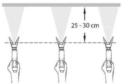
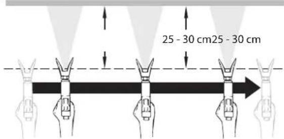
A) The key to a good paint job is an even coating over the entire surface. Keep your arm moving at a constant speed and keep the spray gun at a constant distance from the surface. The best spraying distance is 10-12 inches (25 to 30~cm ) between the spray tip and the surface.
A
C

If very sharp edges result or if there are streaks in the spray jet – increase the operating pressure or dilute the coating material.
5.1 CLEANING A CLOGGED TIP

If the spray pattern becomes distorted or stops completely while pulling the trigger, perform the steps below.
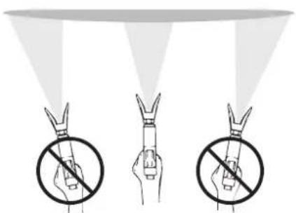
B) Keep the spray gun at right angles to the surface. This means moving your entire arm back and forth rather than just flexing your wrist.
Keep the spray gun perpendicular to the surface, otherwise one end of the pattern will be thicker than the other.
B
-
Turn the relief valve to PRIME (circulation).
-
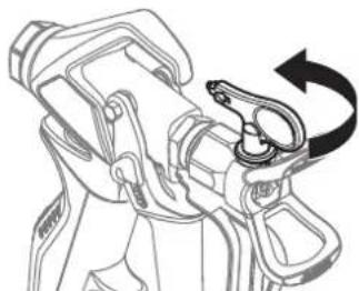
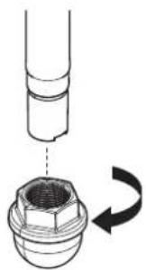
If the tip clogs, rotate the tip handle 180^ until the arrow on the handle is facing the opposite of the spray direction and the handle clicks in the reverse position (Fig. 12).
-
Turn the relief valve to SPRAY ( spray).
12
- Trigger the gun once so that the pressure can blow the clog out. NEVER use the tip in the reverse position for more than ONE trigger pull at a time. This procedure can be repeated until the tip is free of clogging.

The flow from the spray tip is at very high pressure. Contact with any body part may be dangerous. Do not place finger on gun outlet. Do not point the gun at any person. Never operate the spray gun without the proper tip guard.
C) Trigger gun after starting the stroke. Release the trigger before ending the stroke. The spray gun should be moving when the trigger is pulled and released. Overlap each stroke by about 30% . This will ensure an even coating.
5.2 INTERRUPTION OF WORK
| i | Follow these steps if stopping work for up to 20 hours. Only follow these steps if you used latex - or water-based spray materials. |
| i | If you are just simply swapping out material containers, turn the pressure control knob fully counterclockwise to minimum prior to changing the material container. Turn pressure control knob clockwise to previous position when ready to resume spraying. |
- Follow the "Pressure Relief Procedure" found in the Operation section of this manual, section 4.6.
- Place the spray gun in a plastic bag, or drop it into a bucket of water.
- Leave the suction tube and return hose immersed in the coating material or immerse it into a corresponding cleaning agent.
- Cover the coating material with plastic and place unit in a cool, shaded spot to keep material from drying out.
| Attention | If fast-drying or two-component coating material is used, ensure that the unit is rinsed with a suitable cleaning agent within the processing time. |
| i | When ready to being spraying again, remove the plastic from the material container and restart the sprayer by following the steps in section 4.5. |
5.3 HANDLING THE HIGH-PRESSURE HOSE
| i | The unit is equipped with a high-pressure hose specially suited for airless pumps. |
| Danger of injury through leaking high-pressure hose. Replace any damaged high-pressure hose immediately. Never repair damaged high-pressure hoses yourself! |
The high-pressure hose is to be handled with care. Avoid sharp bends and folds: the smallest bending radius is about 8^ (20 cm).
Do not drive over the high-pressure hose. Protect against sharp objects and edges.
Never pull on the high-pressure hose to move the device.
Make sure that the high-pressure hose cannot twist. This can be avoided by using a Wagner spray gun with a swivel joint and hose system.
| i | When using the high-pressure hose while working on scaffolding, it is best to always guide the hose along the outside of the scaffolding. |
| i | The risk of damage rises with the age of the high-pressure hose. Wagner recommends replacing high-pressure hoses after 6 years. |
| i | Use only Wagner original-high-pressure hoses in order to ensure functionality, safety and durability. |
6 CLEANUP
| Attention | The sprayer, hose, and gun should be cleaned thoroughly after daily use. Failure to do so permits material to build up, seriously affecting the performance of the unit. |
| Always spray at minimum pressure with the gun nozzle tip removed when using mineral spirits or any other solvent to clean the sprayer, hose, or gun. Static electricity buildup may result in a fire or explosion in the presence of flammable vapors. |
6.1 SPECIAL CLEANUP INSTRUCTIONS FOR USE WITH FLAMMABLE SOLVENTS
- Always flush spray gun preferably outside and at least one hose length from spray pump.
- If collecting flushed solvents in a one gallon metal container, place it into an empty five gallon container, then flush solvents.
Area must be free of flammable vapors. - Follow all cleanup instructions.
6.2 CLEANING THE SPRAYER
- Follow the "Pressure Relief Procedure" found in the Operation section of this manual, section 4.6.
- Remove the gun tip and tip guard and clean with a brush using the appropriate solvent.
- Place the siphon tube into a container of the appropriate solvent.
|  Attention | Use only compatible solvents when cleaning Check with the fluid manufacturer for the recommended solvent. |
- Place the bleed hose into a metal waste container.
- Set the pressure to minimum by turning the pressure control knob fully counterclockwise.
- Open the bleed valve by rotating the bleed valve handle fully counterclockwise.
- Start the engine or turn on the electric motor.
-
Allow the solvent to circulate through the sprayer and flush the paint out of the bleed hose into the metal waste container.
-
Switch the unit OFF (turn the engine switch OFF).
- Close the bleed valve by rotating the bleed valve handle fully clockwise.
- Start the engine or turn on the electric motor.

Earth the gun by holding it against the edge of the metal container while flushing. Failure to do so may lead to a static electric discharge, which may cause a fire.
- Trigger the gun into the metal waste container until the paint is flushed out of the hose and solvent is coming out of the gun.
- Continue to trigger the spray gun into the waste container until the solvent coming out of the gun is clean.

For long-term or cold weather storage, pump mineral sprits through the entire system.
- Follow the "Pressure Relief Procedure" found in the Operation section of this manual.
- Store the sprayer in a clean, dry area.

Attention
Do not store the sprayer under pressure.
6.3 CLEANING THE OUTSIDE OF THE UNIT
| 4 | Electric models - Make sure the power cord is unplugged to prevent electric shock. |
| !Attention | Danger of short circuit through penetrating water! Never spray down the unit with high-pressure water or high-pressure steam cleaners. Do not put the high-pressure hose into solvents. Use only a wet cloth to wipe down the outside of the hose. |
Wipe down unit externally with a cloth which has been immersed in a suitable cleaning agent.
6.4 CLEANING THE FILTER SCREEN

A clean filter screen always guarantees maximum feed quantity, constant spraying pressure and problem-free functioning of the unit.
SUBMERSIBLE SUCTION SYSTEM
- The filter screen will clog and must be cleaned at least once a day.
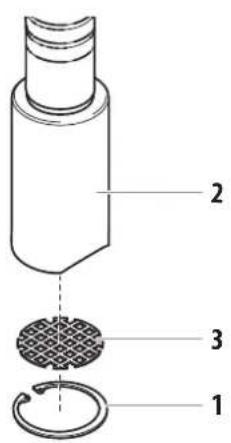
- Remove the retaining ring (Fig. 13, item 1) from the foot valve housing (2).
- Remove the inlet screen (3) from the foot valve housing (2).
- Clean thoroughly with the appropriate solvent.
13
STANDARD SUCTION SYSTEM
- Screw off the filter (Fig. 14) from suction tube.
- Clean or replace the filter.
Carry out cleaning with a hard brush and an appropriate cleaning agent.
14
6.5 CLEANING AIRLESS SPRAY GUN

Clean the spray gun after each use.
- Rinse airless spray gun with an appropriate cleaning agent.
- Clean tip thoroughly with appropriate cleaning agent so that no coating material residue remains.
- Thoroughly clean the outside of the airless spray gun.
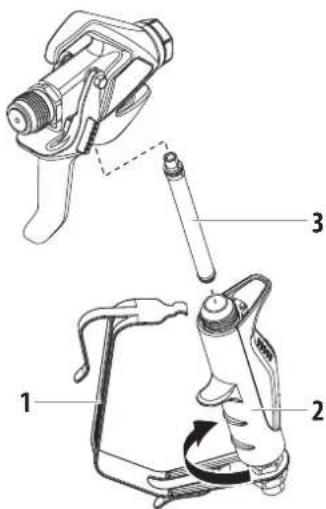
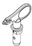
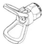
INTAKE FILTER IN AIRLESS SPRAY GUN (FIG. 15)
- Unclip the top of the trigger guard (1) from the gun head.
- Using the bottom of the trigger guard as a wrench, loosen and remove the handle assembly (2) from the gun head.
- Pull the old filter (3) out of the gun head. Clean or replace.
- Slide the new filter, tapered end first, into the gun head.
- Thread the handle assembly into the gun head. Tighten with the trigger wrench.
- Snap the trigger guard back onto the gun head.
15
7 MAINTENANCE
Before proceeding, follow the Pressure Relief Procedure outlined previously in this manual. Additionally, follow all other warnings to reduce the risk of an injection injury, injury from moving parts or electric shock. Always unplug the sprayer before servicing!
7.1 DAILY MAINTENANCE
Two daily procedures are required for routine operator maintenance on this sprayer:
A. Lubricating the upper packings (section 7.2).
B. Cleaning the filter screen (section 6.4).
7.2 LUBRICATING THE UPPER PACKINGS
- Clean out the paint that has seeped past the upper packings into the packing oil reservoir (fig. 16, item 1) above the fluid section.
- Fill the packing oil reservoir 1/2 full with EasyGlide (P/N 0508619) supplied by the factory. This will extend packing life.
(16)
i
Do not over-fill the reservoir so that it overflows and drips into the paint.
7.3 MAINTAINING THE FILTER ASSEMBLY

Clean the filter regularly. Dirty or clogged filters can greatly reduce filtering ability and cause a number of system problems including poor spray patterns, clogged spray tips, etc.
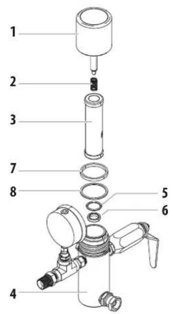
CLEANING (FIG. 17)
To clean the filter, perform the following procedure.
- Follow the "Pressure Relief Procedure" found in the Operation section of this manual.
- Remove the filter cap assembly (1) and spring (2).
- Pull the filter element with ball straight (3) out of the filter body (4).
- Clean inside the filter body, filter element with ball, and filter cap assembly using the appropriate solvent.
⑰
i
Use care in handling parts as dirt, debris, scratches, or nicks may prevent o-rings or gaskets from sealing.
This filter element filters from the inside out. Be sure to clean the filter element thoroughly on the inside. Soak in solvent to loosen hardened paint or replace.
INSPECTION (FIG. 17)
Inspect all parts of the filter assembly before reassembly.
- Inspect the ball inside the filter element. If the ball has pressure cuts or scratches, replace the filter element.
a. If the ball is cut, remove the PTFE o-ring (5) using an o-ring pick and remove the carbide seat (6).
b. Check the seat for nicks or grooves. If the seat is damaged, replace.

Removal of the PTFE o-ring will damage the o-ring and require replacement.
- Remove the spring (2) from the spring guide on the filter cap.
a. Measure the length of the spring uncompressed. If it measures less than 3 / 4'' from end to end, replace.
b. Push the spring back onto the spring guide until it "snaps" back into position. - Inspect the two PTFE gaskets (7,8) and the PTFE o-ring (5) for deformity, nicks, or cuts. Replace, if needed.

The PTFE gaskets, PTFE o-ring, and spring are packaged in Filter Service Kit P/N 930-050.
REASSEMBLY (FIG. 17)
After cleaning and inspecting all parts, reassemble the filter.
- Place the carbide seat (6) into the filter body (4). Make sure the beveled side of the seat is facing up.
- Place the PTFE o-ring (5) into the groove on the outer diameter of the carbide seat (6).
- Place the filter element with ball (3) into the filter body (4).

The top and bottom of the filter element with ball are identical.
- Push the spring (2) back onto the spring guide of the filter cap (1) until it "snaps" back into position, if not already done.
- Place the thin PTFE gasket (8) onto the step at the top of the filter body (4).
- Place the thick PTFE gasket (7) onto the top of the thin gasket (8).
- Tighten the filter cap assembly (1) onto the filter body (4).
7.4 MAINTAINING THE HYDRAULIC SYSTEM

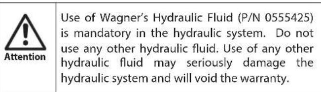
Attention
Use of Wagner's Hydraulic Fluid is mandatory in the HeavyCoat hydraulic system. Do not use any other hydraulic fluid. Use of any other hydraulic fluid may seriously damage the hydraulic system and will void the warranty.
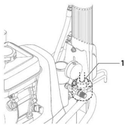
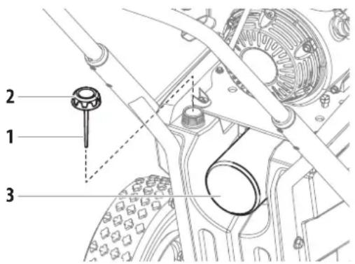
- Check the hydraulic fluid daily. The hydraulic fluid level should be touching the bottom of the dipstick (1). If it is dry, add only Wagner Hydraulic Fluid (P/N 0555425). Never add or change hydraulic fluid except in a clean, dust-free area. Contamination of the hydraulic fluid will shorten hydraulic pump life and may void warranty.

Make sure the unit is on a flat, level surface when checking the hydraulic fluid level.

The hydraulic fluid should be replaced every twelve months. Contact Wagner Service for this.

- The hydraulic system has an external, replaceable hydraulic filter. Change the filter every twelve months.
- The hydraulic pump should not be serviced in the field. If service on the hydraulic pump is required, it must be returned to an authorized Wagner Service Center.
7.5 MAINTAINING THE FLUID SECTION
If the sprayer is going to be out of service for an extended period of time, it is recommended that following cleanup, a kerosene and oil mixture be introduced as a preservative. Packings may tend to dry out from lack of use. This is particularly true of the upper packing set for which upper packing lubricant EasyGlide (P/N 0508619) is recommended in normal usage.
If the sprayer has been out of service for an extended period of time, it may be necessary to prime the pump with solvent. It is extremely important that the threads on the siphon hose coupling are properly sealed. Any air leakage will produce erratic operation of the sprayer and may damage the system. The up and the down strokes should be approximately equal in time (one should not be faster than the other). A fast up or down stroke may indicate air in the system or malfunctioning valve or seats (see the Troubleshooting section).
7.6 HIGH-PRESSURE HOSE
Inspect the high-pressure hose visually for any notches or bulges, in particular at the transition in the fittings. It must be possible to turn the union nuts freely. A conductivity of less than 1M must exist across the entire length.
| ! Attention | Have all the electric tests carried by an Authorized Wagner Service Center. |
| i | The risk of damage rises with the age of the high-pressure hose.Wagner recommends replacing high-pressure hoses after 6 years. |
7.7 BASIC ENGINE MAINTENANCE (GAS ENGINE)
- For detailed engine maintenance and technical specifications refer to the separate gasoline engine manual.
- All service to the engine should be performed by a dealer authorized by the engine manufacturer.
DAILY
- Check engine oil level, and fill as necessary.
- Check gasoline level, and fill as necessary.

Always follow the fueling procedure outlined earlier in this manual.
FIRST 20 HOURS
- Change engine oil.
EVERY 100 HOURS
- Change engine oil.
- Clean the sediment cup.
- Clean and re-gap the spark plug.
- Clean the spark arrester.
WEEKLY
- Remove the air filter cover and clean the element. In very dusty environments, check the filter daily. Replace the element as needed. Replacement elements can be purchased from your local engine manufacturer dealer.
ENGINE OPERATION AND SERVICE
- Clean and oil air filter pad on gasoline engine every 25 hours or once weekly. Do not permit the air intake screen around the fly wheel of the gas engine to load up with paint or trash. Clean it regularly. The service life and efficiency of the gas engine model depends upon keeping the gasoline engine running properly. Change the oil in the engine every 100 hours. Failure to observe this may result in engine overheating. Consult the engine manufacturer's service manual provided.
- To conserve fuel, service life, and efficiency of the sprayer, always operate the gasoline engine at the lowest RPM at which it runs smoothly without laboring and delivers the amount required for the particular painting operation. Higher RPM does not produce higher working pressure. The gasoline engine is connected to the hydraulic pump by a pulley combination designed to produce full paint delivery at maximum RPM.
- The warranty on gasoline engines or electric motors is limited to the original manufacturer.
7.8 SERVICING THE FLUID SECTION
HEAVYCOAT 730

Use of non-Wagner service parts may void warranty. Ask for original parts made by Wagner for best services. This pump should receive a routine servicing after approximately 1,000 hours of use. Earlier servicing is required if there is excessive leakage from the top packing or if pump strokes become faster on one stroke or the other. The use of Wagner EasyGlide (P/N 0508619) is recommended as an upper packing lubricant. Do not substitute oil, water, or solvent for an upper packing lubricant.
DISASSEMBLING THE FLUID SECTION
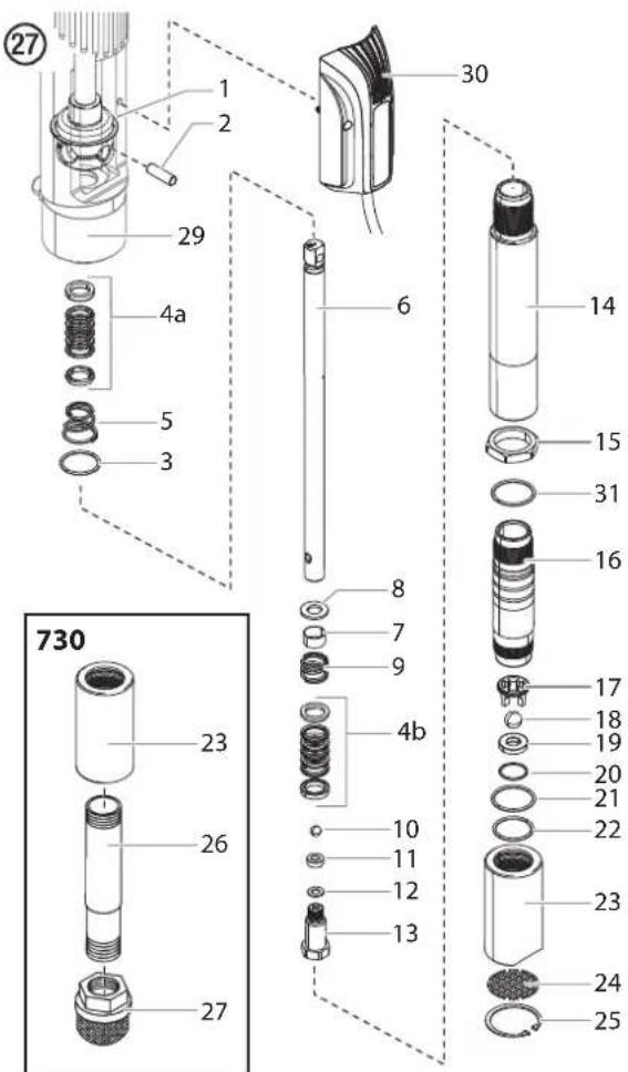
- Using a hex wrench, loosen the captive screws that secure the PCB board assembly (Fig. 27, item 30) to the hydraulic motor cylinder. Once removed, the board can hang by its cord.
- Slide the retainer ring (1) up with a small screwdriver, then push the connecting pin (2) out.
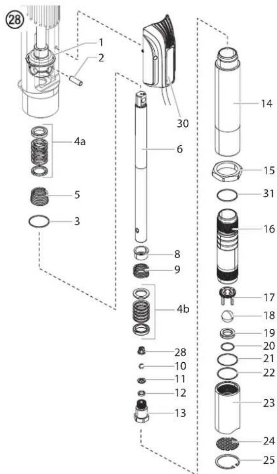
HEAVYCOAT 750 / HEAVYCOAT 770
-
HeavyCoat 730 - Remove the siphon tube (26).
-
Spin the fluid section removal nut (15) counterclockwise so that it bottoms out on the threads on the cylinder (16).
- Place a wrench on the flats of the fluid section removal nut (15). Turn the wrench counterclockwise to loosen the entire fluid section.
- Carefully pull down the fluid section to remove from the hydraulic motor.
- In order to service the fluid section, stabilize it by securing the flats of the fluid section removal nut (15) in a vise.
- Unthread the foot valve housing (23) with a strap wrench.
- Remove upper packing spring (5), and upper packing set (4a) from the motor/pump block.
- Place a wrench on the flats on top of the displacement rod (6). Using a second wrench, loosen and remove the outlet valve housing (13) from the displacement rod (6).
- Remove the seal washer (12), outlet valve seat (11), outlet valve ball (10), outlet valve cage (28, HeavyCoat 750 /
HeavyCoat 770 only), lower packing set (4b), lower packing spring (9) and spring retainer (8).
- Using a 1/2'' extension bar attached to a 1/2'' drive ratchet, insert the end of the extension bar into the square opening of the foot valve cage (17) inside the foot valve housing (23). Unscrew and remove the foot valve cage from the foot valve housing.
- Remove the PTFE o-ring (22), foot valve ball (18), foot valve seat (19), and seat o-ring (20) from the foot valve housing (23).
- Remove the o-ring (21) from the pump cylinder (16)
REASSEMBLING THE FLUID SECTION

Use PTFE tape on all threaded pipe connections.
- Place a new seat o-ring (20) into the groove in the bottom of the foot valve housing (23).
- Inspect the foot valve seat (19) for wear. If one side is worn, flip the seat to the unused side. If both sides are worn, install a new seat. Place the new or flipped seat (worn side down) into the bore at the bottom of the foot valve housing (23).
- Place a new foot valve ball (18) onto the foot valve seat (19). Using a 1/2'' extension bar attached to a 1/2'' drive ratchet, insert the end of the extension bar into the square opening of the foot valve cage (17) and screw the foot valve cage into the foot valve housing (23). Torque the cage to 240 in./lbs. (20 ft./lbs.).
- Insert a new PTFE o-ring (22) into the groove of the foot valve housing (23). Lubricate the o-ring using oil or grease.
- After soaking the leather packings in oil (preferably linseed oil), reassemble the lower packing set (4b). Place the set onto the outlet valve housing (13) with the peak of the "V" packings pointing down toward the hex on the outlet valve housing.

All leather packings must be soaked in hydraulic oil for 15-20 minutes before installation. Soaking the packings too long will cause the packings to swell and create difficulty during reassembly.
-
Inspect the outlet valve seat (11) for wear. If one side is worn, flip the seat to the unused side. If both sides are worn, use a new seat. Insert the outlet valve cage (28, HeavyCoat 750 / 770 only) outlet valve ball (10), new or flipped seat (worn side away from ball), and a new seal washer (12) into the displacement rod (6).
-
Clean the threads on the outlet valve housing (13) and coat the threads with blue Loctite #242. Make sure the Loctite is only on the threads.
- Place the lower packing spring (9) onto the outlet valve housing (13) followed by the spring retainer (8).
- Screw the displacement rod (6) and the outlet valve housing (13) together. Tighten in a vise to 50 ft./Ibs. (68 Nm).
- Insert the PTFE o-ring (3) into the upper grove of the motor/pump block.
- Insert the upper packing set (4a) into the motor/pump block with the peak of the "V" packings pointing up toward the motor.

The packings must be soaked in hydraulic oil before installation.
- Place the upper packing spring (5) into the motor/pump block with the small tapered end facing up toward the motor/pump block.
- Insert the displacement rod (6) up through the upper packings in the motor/pump block.
- Align the holes in the displacement rod (6) and the hydraulic piston rod and insert the connecting pin (2). Replace the retaining ring (1) over the connecting pin.
- HeavyCoat 730 - Thread the long threads of the pump cylinder (16) into the motor/pump block and tighten with a strap wrench.
- Thread the male threads of the cylinder spacer (14) into the motor/pump block and tighten with a strap wrench. Thread the long threads of the pump cylinder (16) into the cylinder spacer (14) and tighten with a strap wrench.
- Place the o-ring (21) onto the top grove of the pump cylinder (16).
- Thread the foot valve housing (23) onto the pump cylinder (16), tighten with a strap wrench.
- HeavyCoat 730 - Install the siphon tube (26).

It is not necessary to over-tighten the foot valve housing. O-ring seals perform sealing function without excessive tightening. Full thread engagement is sufficient.
HeavyCoat 730 - For siphon tube attachment, it is critically important that the threads of the siphon tube fit snugly into the foot valve housing with the tube PTFE taped and sealed to prevent air leakage.
8 TROUBLESHOOTING
8.1 AIRLESS GUN
PROBLEM
A. Spitting gun
B. Gun will not shut off
C. Gun does not spray
CAUSE
- Air in system
- Dirty gun
- Needle assembly out of adjustment
-
Broken or chipped seat
-
Worn or broken needle & seat
- Needle assembly out of adjustment
- Dirty gun
No paint
- Plugged filter or tip
- Broken needle in gun
8.2 FLUID SECTION
PROBLEM
A. Pump delivers on upstroke only or goes up slowly and down fast (commonly called downstroke dive)
B. Pump delivers on down stroke only or goes up fast and down slowly
C. Pump moves up and down fast, delivering material
D. Pump moves up and down slowly when spray gun is shut off
E. Not enough fluid pressure at gun
F. Pump chatters on up or down stroke
CAUSE
- Lower foot valve ball is not seating due to trash or wear
- Material too viscous to siphon.
- Air leaking in on siphon side or damaged siphon hose. Siphon may be too small for heavy material.
- Upper ball is not seating due to trash or wear
- Lower packing set is worn
-
Material container is empty or material is too thick to flow through siphon hose
-
Bottom ball stuck to foot valve seat
- Siphon hose is kinked or loose
- Loose connections. Bleed valve is open partially or bleed valve is worn. Lower packing seat is worn.
-
Upper and/or lower ball not seating
-
Spray tip is worn
- Outlet filter or gun filter is clogged
- Low voltage and/or inadequate amperage
-
Hose size or length is too small or too long
-
Solvent has caused upper packing to swell
SOLUTION
- Inspect connections for air leaks.
- Disassemble and clean.
- Inspect and adjust.
-
Inspect and replace.
-
Replace.
- Adjust.
-
Clean.
-
Check fluid supply.
-
Clean.
- Replace.
SOLUTION
- Remove foot valve assembly. Clean and inspect. Test foot valve by filling with water; if ball fails to seal the seat, replace ball.
- Thin material - contact manufacturer for proper thinning procedures.
-
Tighten all connections between pump and paint container. If damaged, replace. Switch to larger diameter siphon set.
-
Check upper seat and ball with water. If ball fails to seal, replace seat.
-
Replace packing set if worn.
-
Refill with new material. If too thick, remove siphon hose, immerse fluid section in material, and start pump to prime. Add thinner to material. Change to bigger siphon set. Open bleed valve to remove air and restart pump.
- Remove foot valve. Clean ball and seat.
- Straighten.
- Check all connections between pump and gun. Tighten as necessary. If material is flowing from bleed hose, close bleed valve or replace, if necessary. Should none of the above be evident, replace lower packing.
-
Reseat balls by cleaning.
-
Replace.
-
Clean or replace filter.
- Check electrical service. Correct as required.
-
Increase hose size to minimize pressure drop through hose and/or reduce hose length.
-
Replace packing.
8.3 HYDRAULIC MOTORS
PROBLEM
A. Hydraulic motor stalls at bottom or top of stroke; low or intermittent fluid pump pressure; unusual stroke speed; high heat of the hydraulic oil temperature (above 200^ [93°C]).
CAUSE
- Low hydraulic oil level.
- Pressure control setting too low.
- Hydraulic belt or pulley failure.
- Hydraulic piston failure.
- Bound or broken fluid section piston.
- Hydraulic piston rod seal failure
-
Hydraulic piston head seal failure
-
Other
SOLUTION
- Check oil level. Fill if necessary. If the oil level is full, check the controller.
- Make sure the pressure control knob is turned up enough to cycle the motor. If the pressure control setting is okay, then check the belt and pulleys.
- Make sure the key is present in the output shaft of the engine/electric motor and the input shaft of the hydraulic pump. Make sure the belt is not broken and has adequate tension. If belt and pulleys are okay, please contact a Wagner Authorized Service Center.
- Visually check hydraulic piston rod for breaks. If a broken hydraulic piston rod is apparent then remove/ replace hydraulic piston. Depending on where the break occurred the piston coupler may also need to be replaced. Please visit a Wagner Authorized Service Center if assistance is necessary. If hydraulic piston is okay then check for bound/broken fluid section piston
- To check for a bound/broken fluid section piston de-couple the hydraulic piston from the paint piston by removing the dowel pin. Power up the unit. If the hydraulic motor cycles when the hydraulic piston is de-coupled from the paint piston then the problem is most likely in the fluid section. Please visit a Wagner Authorized Service Center if assistance is necessary. If the hydraulic motor still does not cycle then check the hydraulic piston rod seal.
- Remove the hydraulic piston rod seal plug which contains the rod seal, O-ring, and rod wear ring. Check for damage and replace rod seal, O-ring, or rod wear ring if necessary. If rod seal, O-ring, and rod wear ring are okay then check the hydraulic piston head seal.
- Remove the hydraulic piston and inspect/replace the piston head seal and piston head wear ring as needed. During this process check the cylinder bore for damage or uneven wear marks. If the cylinder bore is damaged then replace pump block along with piston head seal and piston head wear ring.
- If problems persist please see a Wagner Certified Service Center.
8.4 SPRAY PATTERNS
PROBLEM
A. Tails
B. Hour
glass
C. Distorted
D. Pattern expanding and contracting (surge)

E. Round
pattern

CAUSE
-
Inadequate fluid delivery
-
Inadequate fluid delivery
-
Plugged or worn nozzle tip
-
Suction leak
-
Pulsating fluid delivery
-
Worn tip
-
Fluid too heavy for tip
SOLUTION
- Fluid not atomizing correctly:
Increase fluid pressure. Change to smaller tip orifice size. Reduce fluid viscosity. Reduce hose length. Clean gun and filter(s). Reduce number of guns using pump.
-
Same as above.
-
Clean or replace nozzle tip.
-
Inspect for suction hose leak.
-
Change to a smaller tip orifice size. Install pulsation dampener in system or drain existing one. Reduce number of guns using pump. Remove restrictions in system; clean tip screen if filter is used.
-
Replace tip.
-
Increase pressure. Thin material. Change nozzle tip.
9 APPENDIX
9.1 SELECTION OF TIP
To achieve faultless and rational working, the selection of the tip is of the greatest importance.
In many cases the correct tip can only be determined by means of a spraying test.
SOME RULES FOR THIS:
The spray jet must be even.
If streaks appear in the spray jet the spraying pressure is either too low or the viscosity of the coating material to high.
- Remedy: Increase pressure or dilute coating material. Each pump conveys a certain quantity in proportion to the size of the tip:
The following principle is valid: large tip = low pressure small tip = high pressure
There is a large range of tips with various spraying angles.
9.2 SERVICING AND CLEANING OF AIRLESS HARD-METAL TIPS
STANDARD TIPS
If a different tip type has been fitted, then clean it according to manufacturer's instructions.
The tip has a bore processed with the greatest precision. Careful handling is necessary to achieve long durability. Do not forget the fact that the hard-metal insert is brittle! Never throw the tip or handle with sharp metal objects.
The following points must be observed to keep the tip clean and ready for use:
- Turn the relief valve handle fully counterclockwise ( Circulation).
- Switch off the gasoline engine / electric motor.
- Dismount the tip from the spray gun.
- Place tip in an appropriate cleaning agent until all coating material residue is dissolved.
- If there is pressure air, blow out tip.
- Remove any residue by means of a sharp wooden rod (toothpick).
- Check the tip with the help of a magnifying glass and, if necessary, repeat points 4 to 6.
9.3 2SPEED TIP TABLE

The innovative changeover nozzle from WAGNER combines two nozzle cores into one nozzle.
2 Speed Tip holder Order no. 027106
TIP TABLE
| Object size Painting material | |||
| Lacquer (L) Emulsion (D) Filler (S) | |||
| Small | D5Nozzles: 111 / 415Order no. 0271 062 | S5Nozzles: 225 / 629Order no. 0271 064 | |
| D7Nozzles: 113 / 417Order no. 0271 063 | |||
| L10Nozzles: 208 / 510Order no. 0271 042 | D10Nozzles: 111 / 419Order no. 0271 045 | S10Nozzles: 527 / 235Order no. 0271 049 | |
| Medium | L20Nozzles: 210 / 512Order no. 0271 043 | D20Nozzles: 115 / 421Order no. 0271 046 | S20Nozzles: 539 / 243Order no. 0271 050 |
| Large | L30Nozzles: 212 / 514Order no. 0271 044 | D30Nozzles: 115 / 423Order no. 0271 047 | S30Nozzles: 543 / 252Order no. 0271 051 |
| X-Large | D40Nozzles: 117 / 427Order no. 0271 048 | ||
| Recommended gun filter red white | - | ||
9.4 AIRLESS TIP TABLE
Wagner TradeTip 3 tip up to 270 bar (27 MPa)
without tip
F thread (11/16 - 16 UN)
for Wagner spray guns
Order no.0289391
without tip
G thread (7/8 - 14 UN)
for Graco/Titan spray guns
Order no. 0289390

All of the tips in the table below are supplied together with the appropriate gun filter.
| Application Tip marking Spray | angle | Bore inch / mm | Spraying width mm 1) | Gun filter Order no. | |
| Water-thinnable and solvent-based paints and varnishes, oils, separating agents | 107 | 10° | 0.007 / 0.18 | 100 | red |
| 207 | 20° | 0.007 / 0.18 | 120 | red | |
| 307 | 30° | 0.007 / 0.18 | 150 | red | |
| 407 | 40° | 0.007 / 0.18 | 190 | red | |
| 109 | 10° | 0.009 / 0.23 | 100 | red | |
| 209 | 20° | 0.009 / 0.23 | 120 | red | |
| 309 | 30° | 0.009 / 0.23 | 150 | red | |
| 409 | 40° | 0.009 / 0.23 | 190 | red | |
| 509 | 50° | 0.009 / 0.23 | 225 | red | |
| 609 | 60° | 0.009 / 0.23 | 270 | red | |
| Synthetic-resin paints PVC paints | 111 | 10° | 0.011 / 0.28 | 100 | red |
| 211 | 20° | 0.011 / 0.28 | 120 | red | |
| 311 | 30° | 0.011 / 0.28 | 150 | red | |
| 411 | 40° | 0.011 / 0.28 | 190 | red | |
| 511 | 50° | 0.011 / 0.28 | 225 | red | |
| 611 | 60° | 0.011 / 0.28 | 270 | red | |
| Paints, primers Fillers | 113 | 10° | 0.013 / 0.33 | 100 | red |
| 213 | 20° | 0.013 / 0.33 | 120 | red | |
| 313 | 30° | 0.013 / 0.33 | 150 | red | |
| 413 | 40° | 0.013 / 0.33 | 190 | red | |
| 513 | 50° | 0.013 / 0.33 | 225 | red | |
| 613 | 60° | 0.013 / 0.33 | 270 | red | |
| 813 | 80° | 0.013 / 0.33 | 330 | red | |
| Fillers Rust protection paints | 115 | 10° | 0.015 / 0.38 | 100 | yellow |
| 215 | 20° | 0.015 / 0.38 | 120 | yellow | |
| 315 | 30° | 0.015 / 0.38 | 150 | yellow | |
| 415 | 40° | 0.015 / 0.38 | 190 | yellow | |
| 515 | 50° | 0.015 / 0.38 | 225 | yellow | |
| 615 | 60° | 0.015 / 0.38 | 270 | yellow | |
| 715 | 70° | 0.015 / 0.38 | 300 | yellow | |
| 815 | 80° | 0.015 / 0.38 | 330 | yellow | |
| Rust protection paints Latex paints Dispersions | 117 | 10° | 0.017 / 0.43 | 100 | white |
| 217 | 20° | 0.017 / 0.43 | 120 | white | |
| 317 | 30° | 0.017 / 0.43 | 150 | white | |
| 417 | 40° | 0.017 / 0.43 | 190 | white | |
| 517 | 50° | 0.017 / 0.43 | 225 | white | |
| 617 | 60° | 0.017 / 0.43 | 270 | white | |
| 717 | 70° | 0.017 / 0.43 | 300 | white | |
| 817 | 80° | 0.017 / 0.43 | 330 | white | |
| Rust protection paints Latex paints Dispersions | 219 | 20° | 0.019 / 0.48 | 120 | white |
| 319 | 30° | 0.019 / 0.48 | 150 | white | |
| 419 | 40° | 0.019 / 0.48 | 190 | white | |
| 519 | 50° | 0.019 / 0.48 | 225 | white | |
| 619 | 60° | 0.019 / 0.48 | 270 | white | |
| 719 | 70° | 0.019 / 0.48 | 300 | white | |
| 819 | 80° | 0.019 / 0.48 | 330 | white | |
| 919 | 90° | 0.019 / 0.48 | 385 | white | |
| Flame retardant 221 | 20° | 0.021 / 0.53 | 120 | white | |
| 321 | 30° | 0.021 / 0.53 | 150 | white | |
| 421 | 40° | 0.021 / 0.53 | 190 | white | |
| 521 | 50° | 0.021 / 0.53 | 225 | white | |
| 621 | 60° | 0.021 / 0.53 | 270 | white | |
| 721 | 70° | 0.021 / 0.53 | 300 | white | |
| 821 | 80° | 0.021 / 0.53 | 330 | white | |
| Roof coatings 223 | 20° | 0.023 / 0.58 | 120 | white | |
| 323 | 30° | 0.023 / 0.58 | 150 | white | |
| 423 | 40° | 0.023 / 0.58 | 190 | white | |
| 523 | 50° | 0.023 / 0.58 | 225 | white | |
| 623 | 60° | 0.023 / 0.58 | 270 | white | |
| 723 | 70° | 0.023 / 0.58 | 300 | white | |
| 823 | 80° | 0.023 / 0.58 | 330 | white | |
| Thick-film materials, Corrosion protection Spray filler | 225 | 20° | 0.025 / 0.64 | 120 | white |
| 325 | 30° | 0.025 / 0.64 | 150 | white | |
| 425 | 40° | 0.025 / 0.64 | 190 | white | |
| 525 | 50° | 0.025 / 0.64 | 225 | white | |
| 625 | 60° | 0.025 / 0.64 | 270 | white | |
| 725 | 70° | 0.025 / 0.64 | 300 | white | |
| 825 | 80° | 0.025 / 0.64 | 330 | white | |
| 227 | 20° | 0.027 / 0.69 | 120 | white | |
| 327 | 30° | 0.027 / 0.69 | 150 | white | |
| 427 | 40° | 0.027 / 0.69 | 190 | white | |
| 527 | 50° | 0.027 / 0.69 | 225 | white | |
| 627 | 60° | 0.027 / 0.69 | 270 | white | |
| 827 | 80° | 0.027 / 0.69 | 330 | white | |
| 229 | 20° | 0.029 / 0.75 | 120 | white | |
| 329 | 30° | 0.029 / 0.75 | 150 | white | |
| 429 | 40° | 0.029 / 0.75 | 190 | white | |
| 529 | 50° | 0.029 / 0.75 | 225 | white | |
| 629 | 60° | 0.029 / 0.75 | 270 | white | |
| 231 | 20° | 0.031 / 0.79 | 120 | white | |
| 331 | 30° | 0.031 / 0.79 | 150 | white | |
| 431 | 40° | 0.031 / 0.79 | 190 | white | |
| 531 | 50° | 0.031 / 0.79 | 225 | white | |
| 631 | 60° | 0.031 / 0.79 | 270 | white | |
| 731 | 70° | 0.031 / 0.79 | 300 | white | |
| 831 | 80° | 0.031 / 0.79 | 330 | white | |
| 233 | 20° | 0.033 / 0.83 | 120 | white | |
| 333 | 30° | 0.033 / 0.83 | 150 | white | |
| 433 | 40° | 0.033 / 0.83 | 190 | white | |
| 533 | 50° | 0.033 / 0.83 | 225 | white | |
| 633 | 60° | 0.033 / 0.83 | 270 | white | |
| 235 | 20° | 0.035 / 0.90 | 120 | white | |
| 335 | 30° | 0.035 / 0.90 | 150 | white | |
| 435 | 40° | 0.035 / 0.90 | 190 | white | |
| 535 | 50° | 0.035 / 0.90 | 225 | white | |
| 635 | 60° | 0.035 / 0.90 | 270 | white | |
| 735 | 70° | 0.035 / 0.90 | 300 | white | |
| 439 | 40° | 0.039 / 0.99 | 190 | white | |
| 539 | 50° | 0.039 / 0.99 | 225 | white | |
| 639 | 60° | 0.039 / 0.99 | 270 | white | |
| Heavy duty applications 243 | 20° | 0.043 / 1.10 | 120 | green | |
| 443 | 40° | 0.043 / 1.10 | 190 | green | |
| 543 | 50° | 0.043 / 1.10 | 225 | green | |
| 643 | 60° | 0.043 / 1.10 | 270 | green | |
| 445 | 40° | 0.045 / 1.14 | 190 | green | |
| 545 | 50° | 0.045 / 1.14 | 225 | green | |
| 645 | 60° | 0.045 / 1.14 | 270 | green | |
| 451 | 40° | 0.051 / 1.30 | 190 | green | |
| 551 | 50° | 0.051 / 1.30 | 225 | green | |
| 651 | 60° | 0.051 / 1.30 | 270 | green | |
| 252 | 20° | 0.052 / 1.32 | 120 | green | |
| 455 | 40° | 0.055 / 1.40 | 190 | green | |
| 555 | 50° | 0.055 / 1.40 | 225 | green | |
| 655 | 60° | 0.055 / 1.40 | 270 | green | |
| 261 | 20° | 0.061 / 1.55 | 120 | green | |
| 461 | 40° | 0.061 / 1.55 | 190 | green | |
| 561 | 50° | 0.061 / 1.55 | 225 | green | |
| 661 | 60° | 0.061 / 1.55 | 270 | green | |
| 263 | 20° | 0.063 / 1.60 | 120 | green | |
| 463 | 40° | 0.063 / 1.60 | 190 | green | |
| 565 | 50° | 0.065 / 1.65 | 225 | green | |
| 665 | 60° | 0.065 / 1.65 | 270 | green | |
| 267 | 20° | 0.067 / 1.70 | 120 | green | |
| 467 | 40° | 0.067 / 1.70 | 190 | green |
1) Spray width at about 30~cm to the object and 100 bar (10 MPa) pressure with synthetic-resin paint 20 DIN seconds.
TESTING OF THE UNIT
For safety reasons, we would recommend having the device checked by an expert as required but at least every 12 months to ensure that it can continue to operate safely.
In the case of unused devices, the check can be postponed until they are next started up.
All (potentially deviating) national inspection and maintenance regulations must also be observed.
If you have any questions, please contact the customer service team at Wagner.
IMPORTANT INFORMATION ON PRODUCT LIABILITY
According to an EU directive, the manufacturer is only liable without limitation for faults in the product if all parts come from the manufacturer or have been approved by the manufacturer and have been mounted to the device and are operated properly. If third-party accessories or spare parts are used, the manufacturer is exonerated wholly or partly from his/her liability if use of the third-party accessories or spare parts have caused a defect in the product. In extreme cases, the relevant authorities can completely prohibit using the entire device.
With original WAGNER accessories and spare parts, compliance with all safety regulations is guaranteed.
NOTE ON DISPOSAL
In observance of the European Directive 2012/19/EU on waste electrical and electronic equipment and implementation in accordance with national law, this product is not to be disposed of together with household waste material but must be recycled in an environmentally friendly way!

Wagner or one of our dealers will take back your used Wagner waste electrical or electronic equipment and will dispose of it for you in an environmentally friendly way. Please ask your local Wagner service centre or dealer for details or contact us direct.
GUARANTEE DECLARATION
(Status 01.02.2009)
1. Scope of guarantee
All Wagner professional colour application devices (hereafter referred to as products) are carefully inspected, tested and are subject to strict checks under Wagner quality assurance. Wagner exclusively issues extended guarantees to commercial or professional users (hereafter referred to as "customer") who have purchased the product in an authorised specialist shop, and which relate to the products listed for that customer on the Internet under www.wagner-group.com/profi-guarantee.
The buyer's claim for liability for defects from the purchase agreement with the seller as well as statutory rights are not impaired by this guarantee.
We provide a guarantee in that we decide whether to replace or repair the product or individual parts, or take the device back and reimburse the purchase price. The costs for materials and working hours are our responsibility. Replaced products or parts become our property.
2. Guarantee period and registration
The guarantee period amounts to 36 months. For industrial use or equal wear, such as shift operations in particular, or in the event of rentals it amounts to 12 months.
Systems driven by petrol or air are also guaranteed for a 12 month period.
The guarantee period begins with the day of delivery by the authorised specialist shop. The date on the original purchase document is authoritative.
For all products bought in authorised specialist shops from 01.02.2009 the guarantee period is extended to 24 months providing the buyer of these devices registers in accordance with the following conditions within 4 weeks of the day of delivery by the authorised specialist shop.
Registration can be completed on the Internet under www.wagner-group.com/profi-guarantee.
The guarantee certificate is valid as confirmation, as is the original purchase document that carries the date of the purchase. Registration is only possible if the buyer is in agreement with having the data being stored that is entered during registration. When services are carried out under guarantee the guarantee period for the product is neither extended nor renewed.
Once the guarantee period has expired, claims made against the guarantee or from the guarantee can no longer be enforced.
3. Handling
If defects can be seen in the materials, processing or performance of the device during the guarantee period, guarantee claims must be made immediately, or at the latest within a period of 2 weeks.
The authorised specialist shop that delivered the device is entitled to accept guarantee claims. Guarantee claims may also be made to the service centres named in our operating instructions. The product has to be sent without charge or presented together with the original purchase document that includes details of the purchase date and the name of the product. In order to claim for an extension to the guarantee, the guarantee certificate must be included.
The costs as well as the risk of loss or damage to the product in transit or by the centre that accepts the guarantee claims or who delivers the repaired product, are the responsibility of the customer.
4. Exclusion of guarantee
Guarantee claims cannot be considered
for parts that are subject to wear and tear due to use or other natural wear and tear, as well as defects in the product that are a result of natural wear and tear, or wear and tear due to use. This includes in particular cables, valves, packaging, jets, cylinders, pistons, means-carrying housing components, filters, pipes, seals, rotors, stators, etc. Damage due to wear and tear that is caused in particular by sanded coating materials, such as dispersions, plaster, putty, adhesives, glazes, quartz foundation. -in the event of errors in devices that are due to non-compliance with the operating instructions, unsuitable or unprofessional use, incorrect assembly and/or commissioning by the buyer or by a third party, or utilisation other than is intended, abnormal ambient conditions, unsuitable coating materials, unsuitable operating conditions, operation with the incorrect mains voltage supply/frequency, over-operation or defective servicing or care and/or cleaning.
- for errors in the device that have been caused by using accessory parts, additional components or spare parts that are not original Wagner parts.
-for products to which modifications or additions have been carried out.
for products where the serial number has been removed or is illegible
for products to which attempts at repairs have been carried out by unauthorised persons.
for products with slight deviations from the target properties, which are negligible with regard to the value and usability of the device.
-for products that have been partially or fully taken apart.
5. Additional regulations.
The above guarantees apply exclusively to products that have been bought by authorised specialist shops in the EU, CIS, Australia and are used within the reference country.
If the check shows that the case is not a guarantee case, repairs are carried out at the expense of the buyer.
The above regulations manage the legal relationship to us conclusively. Additional claims, in particular for damages and losses of any type, which occur as a result of the product or its use, are excluded from the product liability act except with regard to the area of application.
Claims for liability for defects to the specialist trader remain unaffected.
German law applies to this guarantee. The contractual language is German. In the event that the meaning of the German and a foreign text of this guarantee deviate from one another, the meaning of the German text has priority.
J. Wagner GmbH
Division Professional Finishing
Otto Lilienthal Strasse 18
88677 Markdorf
Federal Republic of Germany
Subject to modifications
Warning!
GEFAHR: GEFAHRLICHE DAMPFE
Division Professional Finishing
Otto Lilienthal Strasse 18
88677 Markdorf
go.wagner-group.com/profi
Attention!
RISQUE: FLEXIBLE À HAUTE PRESSION
circulation projection
9.3 TABLEAU DES BUSES 2SPEED TIP
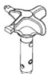
INDICATION DE MISE AU REBUT
Division Professional Finishing
Otto Lilienthal Strasse 18
88677 Markdorf
| FILTER ASSEMBLY SPECIFICATIONS Maximum Working Pressure: 5000 psi (34.5 MPa) |
| Filter Area: 18 In² (116 cm²) |
| Outlet Ports: (1) 1/4" NPT(F) for bleed valve (1) 3/8" NPT(F) with 1/4 NPSM(M) hose connection (2) 3/8" NPT(F) plugged for additional gun hookup. |
| Wetted Parts: Carbon steel with electroless nickel and cadmium plating, stainless steel, tungsten carbide, PTFE |
GB Wagner Spraytech (UK) Limited
Innovation Centre
Silverstone Park
Silverstone
Northants NN12 8GX
Great Britain
Tel.01327368410
enquiries@wagnerspraytech.co.uk
B WSB Finishing Equipment
Veilinglaan 56-58
1861 Meise-Wolvertem
Belgium
Tel. +32/2/2694675
Telefax +32/2/269 7845
info@wagner-wsb.nl
E Makimport Herramentas, S.L.
C/Mejico n°6
NL WSB Finishing Equipment BV
De Heldinnenlaan 200,
3543 MB Utrecht
Netherlands
Tel. +31/ 30/241 41 55
Telefax +31/ 30/241 17 87
info@wagner-wsb.nl
D J.Wagner GmbH
Telefax 04.42.53.44.36