GDS3702 - Intercom GRANDSTREAM - Free user manual and instructions
Find the device manual for free GDS3702 GRANDSTREAM in PDF.
| Product Type | Intercom |
| Brand | Grandstream |
| Model | GDS3702 |
| Power Supply | PoE IEEE 802.3af (Class 3, 12.95 W) or DC 12 V adapter (1 A minimum, not included) |
| Network Connectivity | Ethernet RJ45 10/100 Mbps |
| Additional Interfaces | RS485, Wiegand (input/output), alarm (2 inputs, 2 outputs), electric lock (relay NO/COM/NC) |
| Operating Temperature Range | -30 °C to 60 °C |
| Storage Temperature Range | -35 °C to 60 °C |
| Operating Humidity | 10% to 90% RH (non-condensing) |
| Mounting | Surface mount (with included bracket) or flush mount (optional kit) |
| Protection | Tamper-proof screws, sealing rubber gasket |
| Package Contents | Quick installation guide, back cover, screws, anchors, hex key, silicone plugs |
| Default IP Configuration | DHCP (fallback address 192.168.1.168 if no DHCP server) |
| Web Interface Access | HTTPS, port 443 (default) |
| Default Credentials | Username: admin; password: random (on device sticker) |
| Compliance | PoE 802.3af Class 3 |
| Recommended Installation Tools | Universal pliers, 2.5 mm flat screwdriver, hex key (included) |
| Recommended Network Cable | Cat5e or Cat6 (not included) |
| Security Features | Alarm input/output, open detection (via alarm contact) |
| Search Software | GS_Search tool available at www.grandstream.com/support/tools |
Frequently Asked Questions - GDS3702 GRANDSTREAM
User questions about GDS3702 GRANDSTREAM
0 question about this device. Answer the ones you know or ask your own.
Ask a new question about this device
Download the instructions for your Intercom in PDF format for free! Find your manual GDS3702 - GRANDSTREAM and take your electronic device back in hand. On this page are published all the documents necessary for the use of your device. GDS3702 by GRANDSTREAM.
USER MANUAL GDS3702 GRANDSTREAM
Grandstream Networks, Inc.
126 Brookline Ave, 3rd Floor
Boston, MA 02215. USA
Tel : +1 (617) 566 - 9300
natural_image
Exterior view of a modern white electronic device labeled 'GRANDSTREAM' with a control button (no additional text or symbols visible)GDS3702
Intercom Access System
Quick Installation Guide
For Warranty and RMA information, please visit www.grandstream.com
Content
English....1
简体中文....10
Español....19
Français....28
Deutsch....37
Italiano....46
Русский....55
Português.... 64
Polski....73
PRECAUTIONS
- Do not attempt to disassemble or modify the device.
- Strictly follow the requirement of power source.
- Do not expose this device to temperatures out the range of -30°C to 60°C for operating and -35°C to 60°C for storage
- If the temperature is under -30 degree, the device will take about 3 minutes to heat up itself before booting and operating.
- Do not expose this device to environments outside of the following humidity range: 10-90% RH (non-condensing).
- Please strictly follow the instruction to install or hire professionals to install properly.
PACKAGE CONTENTS

text_image
1 x GDS3702 4 x Rubber Gaskets 1 x Installation Bracket 6 x Back Panel Screws 1 x Drilling Template 6 x Bracket Screws and Anchors 4 x Anti-tamper Screws 1 x Anti-tamper Hex Key 1 x Wiegand Cable 1x Quick Installation Guide 1 x Frame Back Cover\~1\~\~2\~
MOUNTING GDS3702
On-Wall (Surface) Mounting
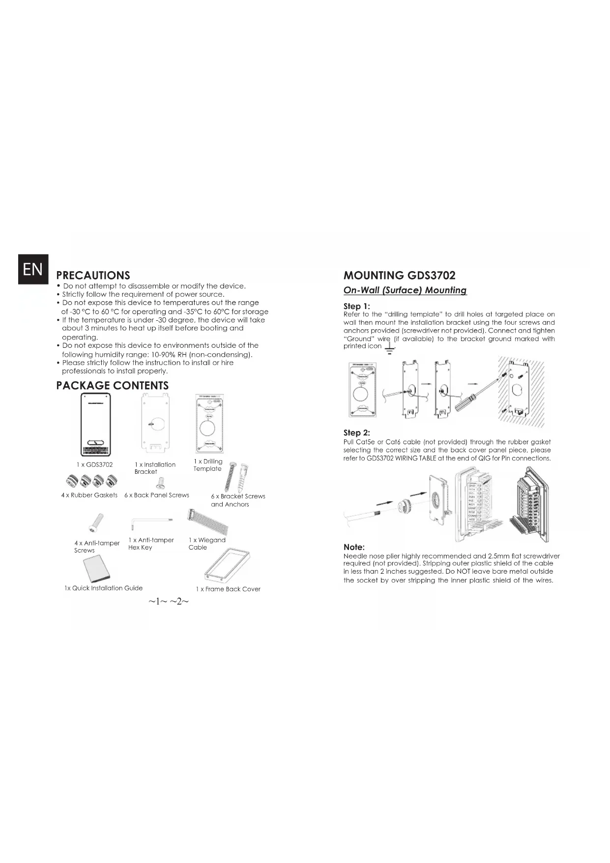
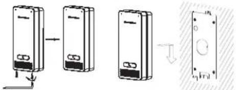
Step 1:
Refer to the "drilling template" to drill holes at targeted place on wall then mount the installation bracket using the four screws and anchors provided (screwdriver not provided). Connect and tighten "Ground" wire (if available) to the bracket ground marked with printed icon.
text_image
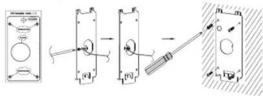
Diagram showing a mechanical assembly with labeled components and directional arrows indicating motion or assembly steps.Step 2:
Pull Cat5e or Cat6 cable (not provided) through the rubber gasket selecting the correct size and the back cover panel piece, please refer to GDS3702 WIRING TABLE at the end of QIG for Pin connections.
text_image
Technical diagram showing exploded view of a mechanical assembly with labeled components and directional arrows indicating assembly or assembly.Note:
Needle nose plier highly recommended and 2.5mm flat screwdriver required (not provided). Stripping outer plastic shield of the cable in less than 2 inches suggested. Do NOT leave bare metal outside the socket by over stripping the inner plastic shield of the wires.
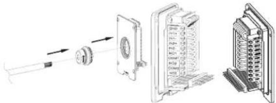
Step 3:
Make sure the "Back Cover Frame" is in place, the wired back cover panel is good. Flush the back cover panel piece with the whole back surface of device, tighten it using the screws provided.
text_image
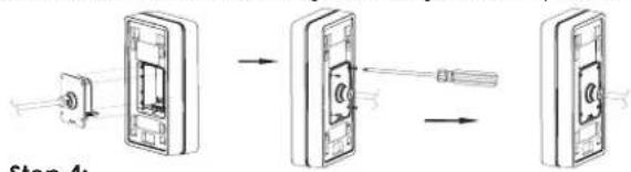
Step 4:Step 4:
Take out the two preinstalled anti-tamper screws using the hex key provided. Carefully align the GDS3702 to the metal bracket on wall, press and pull the GDS3702 down to the right position.
text_image
Diagram illustrating a step-by-step assembly of a device with labeled components and directional arrows indicating process flow.Step 5:
Install the two anti-tamper screws back using the hex key provided (do NOT over tighten the screws). Cover the two screw holes on the bottom of "Back Cover Frame" piece using the two silicon plugs provided. Final check and finish the installation.
flowchart
graph TD
    A["Device 1"] --> B["Device 2"]
    B --> C["Device 3"]
In-Wall (Embedded) Mounting
Please refer to the "In-Wall (Embedded) Mouting Kit", which can be purchased separately from Grandstream.
\~3\~ \~4\~
CONNECTING THE GDS3702
Refer to the illustration below and follow the instructions on the next page.
POWER OFF GDS3702 when connecting wires or inserting/removing the back cover panel piece!
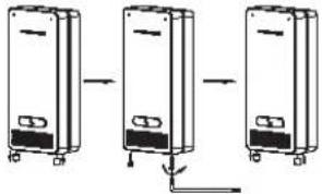
Option A:
RJ45 Ethernet Cable to (Class 3) Power over Ethernet (PoE) Switch.
text_image
Option B: DC12V, 1A minimum Power Source (not provided) Network Port Power Port 12VNote:
Choose Option A if using PoE switch (Class 3); OR: Option B if using 3rd party power source.
Option A
Plug an RJ45 Ethernet cable into the (Class 3) Power over Ethernet(PoE) switch.
Option B
Step 1:
Select an external DC12V, minimum 1A power source (not provided). Wire correctly the "+,-" cable of the power into the "12V, GND" connector of the GDS3702 socket (refer to the previous mounting page for instruction). Connect the power source.
Step 2:
Plug an RJ45 Ethernet cable into a network switch/hub or router.
Note:
Please refer to "Step 2" of "MOUNTING GDS3702" and "GDS3702 WIRING TABLE" at the end of QIG for all the wiring and connection illustration and instructions.
GDS3702 CONFIGURATION
The GDS3702 is by default configured to obtain the IP address from DHCP server where the unit is located.
In order to know which IP address is assigned to your GDS3702, please use GS_Search tool as illustrated in following steps.
Note:
If no DHCP server is available, the GDS3702 default IP address (after 5 minutes DHCP timeout) is 192.168.1.168.
Step 1: Download and install GS_Search tool:
http://www.grandstream.com/support/tools
Step 2: Run the Grandstream GS_Search tool on a computer connected to same network/DHCP server.
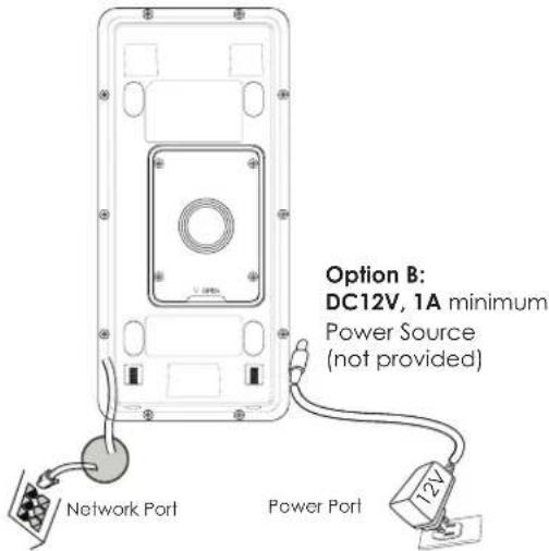
Step 3: Click on search button to start device detection.
Step 4: The detected devices will appear in the output field as below.
text_image
Search Index Model Version Server Name IP HTTP Port FTP Port MAC DOOR/EN/0376/02 1.0.1.10 COD/02 152188.1.09 440 0 9008 8234 8526 Screen Add IP Address Configuration SoftConfiguration OKP Use DHCP New IP Ping Sub Net Mask Data Way Health IDStep 5: Open the web browser and type the displayed IP address of GDS3702 with leading https:// to access the web GUI. (For security reasons, the default web access of GDS3702 is using HTTPS and port 443.)
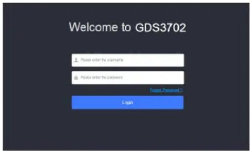
Step 6: Enter username and password to login.
(The default administrator username is "admin" and the default random password can be found at the sticker on the GDS3702).
Note: For security reasons, make sure to change the default admin password from System Settings > User Management.
text_image
Welcome to GDS3702 Please enter the username Please enter the password Exit Password 1 LoginStep 7: After login into the webGUI, click the left side menu in the web interface for more detailed and advanced configuration.
The GNU GPL license terms are incorporated into the device firmware and can be accessed via the Web user interface of the device at my_device_ip/gpl_license. It can also be accessed here: http://www.grandstream.com/legal/open-source-software
To obtain a CD with GPL source code information please submit a written request to: info@grandstream.com
GDS3702 WIRING TABLE
| Jack Pin Signal Function | ||
| J2(Basic)3.81mm | 1 TX+ (Orange/White) | Ethernet,PoE 802.3af Class3.12.95W |
| 2 TX- (Orange) | ||
| 3 RX+ (Green/White) | ||
| 4 RX- (Green) | ||
| 5 PoE_SP2 (Blue + Blue/White) | ||
| 6 PoE_SP1 (Brown + Brown/White) | ||
| 7 RS485_B | RS485 | |
| 8 RS485_A | ||
| 9 GND | Power Supply | |
| 10 I2V | ||
| J3(Avanced)3.81mm | 1 GND Alarm GND | |
| 2 ALARM1_IN+ | Alarm IN | |
| 3 ALARM1_IN- | ||
| 4 ALARM2_IN+ | ||
| 5 ALARM2_IN- | ||
| 6 NO1 | Alarm Out | |
| 7 COM1 | ||
| 8 NO2 | Electric Lock9 COM2 | |
| 10 NC2 | ||
| J4(Special)2.0mm | 1 GND (Black) Wiegand Power | GND |
| 2 WG_D1_OUT (Orange) | Wiegand Output Signal | |
| 3 WG_D0_OUT (Brown) | ||
| 4 LED (Blue) | Wiegand Output LED Signal | |
| 5 WG_D1_IN (White) | Wiegand Input Signal | |
| 6 WG_D0_IN (Green) | ||
| 7 BEEP (Yellow) | Wiegand Output BEEP Signal | |
| 8 5V (Red) Wiegand Power Output | put | |
For more details regarding GDS3702 wiring, please refer to User Manual.
| Electric Lock GDS3702 | Connection | Door | ||||
| Type Power On Power Off NC2 | NO2 COM2 | Normal Status | ||||
| Fail Safe | Lock Open | ■ ■ | Lock | |||
| ■ ■ | Open | |||||
| Fail Secure | Open Lock | ■ ■ | Lock | |||
| ■ ■ | Open | |||||
| NOTE:* Please select the correct wiring based on different electric strike/lock and the normal status of door.* Electric Magnetic Lock will work at Fall Safe mode ONLY. | ||||||
text_image
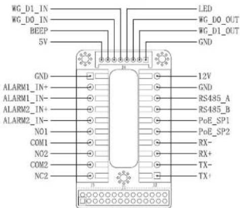
WG_D1_IN WG_DO_IN BEEP 5V GND ALARM1_IN+ ALARM1_IN- ALARM2_IN+ ALARM2_IN- NO1 COM1 NO2 COM2 NC2 LED WG_DO_OUT WG_D1_OUT GND 12V GND RS485_A RS485_B PoE_SP1 PoE_SP2 RX- RX+ TX- TX+Note:
1) Power PoE_SP1, PoE_SP2 with DC, the voltage range is 48V\~57V, no polarity.
2) Power with PoE the cable wiring:
• PoE_SP1, brown and brown/white binding
- PoE_SP2, blue and blue/white binding
3) DC Power could be correctly sourced from qualified PoE Injector.
This product is covered by one or more of the U.S. patents (and any foreign patent counterparts thereto) identified at www.cmspatents.com.
ZH
注意事项
text_image
Technical diagram showing a mechanical assembly with labeled components and directional arrows indicating motion or assembly.步骤2:
text_image
Technical diagram showing assembly of a device with labeled components and directional arrows indicating assembly steps.注意事项:
text_image
Diagram showing three stages of a device with labeled components and an arrow indicating transformation or assembly.步骤 5:
text_image
Welcome to GDS3702 Please enter the username Please enter the password Login Cancel/登录 1...text_image
Diagram showing three-step installation of a door panel with a screwdriver, including component assembly and mounting details.Paso 2:
text_image
Technical diagram showing exploded view of a mechanical assembly with labeled components and directional arrows indicating assembly or assembly.Nota:
text_image
Diagram showing a device assembly process with labeled components and directional arrows indicating assembly steps.Paso 5:
text_image
Welcome to GDS3702 Please enter the username Please enter the password Export Delivered 1 Logintext_image
Technical diagram showing a mechanical assembly with labeled components and directional arrows indicating assembly steps.Etape 2:
text_image
Technical diagram showing exploded view of a mechanical assembly with labeled components and directional arrows indicating assembly steps.Remarque:
text_image
Diagram illustrating a cable installation process with labeled components and directional arrowsEtape 4:
text_image
Diagram showing three stages of a device with labeled components and a magnified view of the internal structure.Etape 5:
Plug an RJ45 Ethernet cable into a network switch/hub or router.