SMIGMA 250.IGBT - Welding machine Stamos - Free user manual and instructions
Find the device manual for free SMIGMA 250.IGBT Stamos in PDF.

| Product type | Professional MIG/TIG/MMA welding machine |
| Brand | Stamos |
| Model | S-MIGMA 250.IGBT |
| Input voltage | 230 V~ / 50 Hz |
| Rated input current (MMA) | 33 A |
| Rated input current (TIG) | 22.5 A |
| Rated input current (MIG) | 29.5 A |
| Open circuit voltage | 62 V |
| Welding current range MMA | 15 - 250 A |
| Welding current range TIG | 15 - 250 A |
| Welding current range MIG | 50 - 250 A |
| Duty cycle at 60% | 250 A (MMA/TIG/MIG) |
| Duty cycle at 100% | 193 A (MMA/TIG/MIG) |
| Welding modes | MIG, TIG, MMA, Flux |
| Power supply | Single-phase, with ground plug |
| Cooling | Integrated fan |
| Thermal protection | Overheat indicator with automatic shutdown |
| Safety instructions | Mandatory full body protection (mask, gloves, shoes) |
| Cleaning | After each use, unplug and let cool |
| Compliance | With European directives |
Frequently Asked Questions - SMIGMA 250.IGBT Stamos
User questions about SMIGMA 250.IGBT Stamos
0 question about this device. Answer the ones you know or ask your own.
Ask a new question about this device
Download the instructions for your Welding machine in PDF format for free! Find your manual SMIGMA 250.IGBT - Stamos and take your electronic device back in hand. On this page are published all the documents necessary for the use of your device. SMIGMA 250.IGBT by Stamos.
USER MANUAL SMIGMA 250.IGBT Stamos
The operation manual must be read carefully.
Never dispose of electrical equipment together with household waste.
This machine conforms to the CE declarations
Use full body protective clothes.
Attention! Wear protective gloves.
Safety goggles must be worn.
Protective footwear must be worn.
Attention! Hot surface may cause burns
A Attention! Risk of fire or explosion.
Attention! Harmful fumes, danger of poisoning. Gases and vapours may be hazardous to health. Welding gases and vapours are released during welding. Inhalation of these substances may be hazardous to health.
Use a welding mask with appropriate filter shading.
CAUTION! Harmful radiation of welding arc.
Do not touch the parts that are under voltage/power.
PLEASE NOTE! Drawings in this manual are for illustration purposes only and in some details it
may differ from the actual product.
The original operation manual is in German. Other language versions are translations from German.
I.SAFETY OF USE
I.1 GENERAL NOTES
Take care of your own safety and the one of third parties by reviewing and strictly following the instructions, included in the operating manual of the device.
Only qualified and skilled personnel can be allowed to start, operate, maintain and repair the machine.
The machine must never be operated contrary to its intended purpose.
1.2 PREPARATION OF WELDING WORK SITE
WELDING OPERATIONS MAY CAUSE FIRE OR EXPLOSION
- Strictly follow the occupational health and safety regulations applicable to welding operations and make sure to provide appropriate fire extinguishers at the welding work site.
- Never carry out welding operations in flammable places that pose the risk of material ignition.
- Never carry out welding operations in an atmosphere containing flammable particles or vapours of explosive substances.
- Remove all flammable materials within 12 meters from the welding operations site and if removal is not possible cover flammable materials with fire retardant covering.
- Use safety measures against sparks and glowing particles of metal.
- Make sure that sparks or hot metal splinters do not penetrate through the slots or openings in the coverings, shields or protective screens.
- Do not weld tanks or barrels that contain or have contained flammable substances. Do not weld in the vicinity of such containers and barrels.
- Do not weld pressure vessels, pipes of pressurised installations or pressure trays.
Always ensure adequate ventilation.
It is recommended to take a stable position prior to welding.
1.3 PERSONAL PROTECTION EQUIPMENT
ELECTRIC ARC RADIATION CAN CAUSE DAMAGE TO EYES AND SKIN
- When welding, wear clean, oil stain free protective clothing made of non-flammable and non-conductive material (leather, thick cotton), leather gloves, high boots and protective hood.
- Before welding remove all flammable or explosive items, such as propane butane lighters or matches.
- Use facial protection (helmet or shield) and eye protection, with a filter featuring a shade level matching the sight of the welder and the welding current. The safety standards suggest colouring No. 9 (minimum No. 8) for each current below 300 A. A lower colouring of the shield can be used if the arc is covered by the workpiece.
Always use approved safety glasses with side protection under the helmet or any other cover. - Use guards for the welding operations site in order to protect other people from the blinding light, radiation or projections.
- Always wear earplugs or another hearing protection to protect against excessive noise and to avoid spatter entering the cars.
- Bystanders should be warned to not look at the arc.
1.4 PROTECTION AGAINST ELECTRIC SHOCK
ELECTRIC SHOCK CAN BE LETHAL
- The power cable must be connected to the nearest socket and placed in a practical and secure position. Positioning the cable negligently in the room and on a surface which was not checked must be avoided as it can lead to electrocution or fire.
- Touching electrically charged elements can cause electrocution or serious burns.
- Electrical arc and the working area are electrically charged during the power flow.
- Input circuit and inner power circuit of the devices are also under voltage charge when the power supply is turned on.
The elements under the voltage charge must not be touched. - Dry, insulated gloves without any holes and protective clothing must be worn at all times.
Insulation mats or other insulation layers, big enough as not to allow for body contact with an object or the floor, must be placed on the floor.
The electrical arc must not be touched. - Electrical power must be shut down prior to cleaning or electrode replacement.
- It must be checked if the earthing cable is properly connected or the pin is correctly connected to the earthed socket. Incorrect connection of the earthing can cause life or health hazard.
- The power cables must be regularly checked for damage or lack of insulation. Damaged cables must be replaced. Negligent insulation repair can cause death or serious injury.
The device must be turned off when it is not in use.
The cable mustn't be wrapped around the body. - A welded object must be properly grounded.
- Only equipment in good condition can be used.
- Damaged device elements must be repaired or replaced. Safety belts must be used when working at height.
- All fitting and safety elements must be stored in one place.
From the moment of turning on the release, the handle end must be kept away from the body. - The chassis ground must be mounted to the welded element or as close to it as possible (e.g. to a work table).
THE DEVICE CAN STILL BE UNDER VOLTAGE UPON FEEDER DISCONNECTION
- The voltage in the input capacitor must be checked upon turning off the device and disconnecting it from the power source. One must make sure that the voltage value is equal to zero. Otherwise, the device elements must not be touched.
1.5 GASES AND FUMES
PLEASE NOTE! GAS MAY BE LETHAL OR DANGEROUS TO HUMAN HEALTH!
Always keep a certain distance from the gas outlet
- When welding, ensure good ventilation. Avoid inhalation of the gas.
EN
EN
- Chemical substances (lubricants, solvents) must be removed from the surfaces of welded objects as they burn and emit toxic smokes under the influence of temperature.
-
The welding of galvanised objects is permitted only when efficient ventilation is provided with filtration and access to fresh air. Zinc fumes are very toxic, an intoxication symptom is the so called zinc fever.
-
TECHNICAL DATA
| Product name WELDING MACHINE | |
| Model S-MIGMA 250.IGBT | |
| Voltage / frequency 230V~ / 50 Hz | |
| Rated input current [A] 33 (MMA) | |
| 22.5 (TIG) | |
| 29.5 (MIG) | |
| No-load voltage [V] 62 (MMA / TIG / MIG) | |
| MMA welding current [A] 15-250 | |
| TIG welding current [A] 15-250 | |
| MIG welding current [A] 50-250 | |
| Welding current at 60% duty cycle [A] 250 (MMA/TIG/MIG) | |
| Welding current at 100% duty cycle [A] 193 (MMA/TIG/MIG) | |
3.OPERATION
3.1 GENERAL NOTES
The device must be applied according to its purpose, with observance of OHS regulations and restrictions resulting from data included in the rating place (IP level, operation cycle, supply voltage, etc.).
The machine must not be opened as it will cause warranty loss and, in addition, exploding, unshielded elements can cause serious injuries.
- The producer does not bear any responsibility for technical changes in the device or material losses caused by the introduction of the said changes.
In case of incorrect device operation, contact the service centre.
- Louvers must not be shielded - the welder must be positioned at 30 cm distance from objects surrounding it.
The welder must not be kept under your arm or near to your body.
- The machine must not be installed in rooms with aggressive environments, high dustiness and near devices with high electromagnetic field emission.
3.2 DEVICE STORAGE
The machine must be protected against water and moisture.
- The welder must not be positioned on heated surfaces.
The device must be stored in a dry and clean room.
3.3 CONNECTING THE DEVICE
3.3.1 Connecting the power
- Connection of the device must be performed by a qualified person. In addition, a person with required qualifications should check if the earthing or electrical installation with protection system is in line with the safety regulations and if they operate correctly.
The device must be placed near the work station. -
Connection of excessively long conduits to the machine must be avoided.
One-phase welders should be connected to the socket fitted with an earthing prong. -
Welders powered from a 3-Phase network are delivered without a plug, the plug must be obtained independently and installation should be assigned to a qualified person.
PLEASE NOTE! THE DEVICE MAY ONLY BE USED UPON CONNECTION TO AN INSTALLMENT WITH A PROPERLY FUNCTIONING FUSE!
4. OPERATION
S-MIGMA 250.IGBT WELDING MACHINE
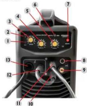
Machine description:
Front view:
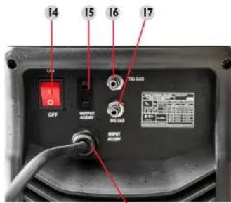
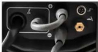
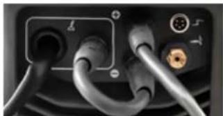
Rear view:
18
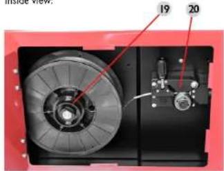
Inside view:

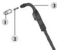
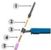
MIG torch:
-
Nozzle
-
Collet
- MIG welding torch
EN
EN
No. Function and description
2. Power on Indicator
6. TIG/MIG - MMA switch
8. TIG control button connector
13. MIG connection socket
I. ERROR INDICATOR = The indicator lights in the following two situations: a) If the machine has malfunctioned and cannot be operated. b) If the cutting device has exceeded the standard working time, the protection mode is initiated and the machine will stop functioning. This means that the machine is now being cooled in order to be able to restore the temperature control again after the device has overheated. Therefore, the machine is stopped. During this process, the red warning light on the front panel lights up. In this case it is not necessary to unplug the device. The ventilation system may be left on in order to enhance the cooling of the machine. When the red light goes dark, this means that the temperature is set to the normal level and the unit can be put back into operation.
3 Wire feed rate adjustment knob
4. MIG voltage adjustment knob
5. TIG / MMA welding current adjustment knob
7. INCHING - upon pressing this button, the welder starts with the wire feed. The wire will be fed until the button is released. It is used to feed the wire, e.g. upon the reel replacement.
9. TIG torch current-gas cable socket
10. "Negative output
11. n + ^+ Positive output
12. Welding polarisation change socket. Connected to the positive pole - MIG welding Connected to the negative pole - FLUX welding
14. On/off switch
15.230VCO2heater socket
16. TIG welding gas connector
17. MiG welding gas connector
18. Power cable
19.Wire reel
20. Wire guide
21. Welding polarisation change cable (MIG/FLUX)

TIG Grift:
- Back cap, long
- Collet
- Torch handle
- Coilet inside housing
- Ceramic nozzle
5. CABLE CONNECTIONS
INSTRUCTIONS FOR CABLE CONNECTIONS:
Limit the number of cables connected to the unit at the same time. For example, during MIG welding, no other welding cables (e.g. TIG) may be connected, because then the MIG welding will not work. This procedure ensures proper functioning of the machine and the safety of the worker.
MMA WELDING MODE
I. Set the switch (6) to MMA welding mode.
2 Connect the mass cable to the socket marked with ^ + ^ (II).
3. Then connect the cable with MMA electrode holder to socket marked with the _w^ sign (10). WARNING! The polarization of the cables can be different! All polarisation information should be shown on the packaging supplied by the electrode manufacturer.
4. Now you can connect the power cord and turn the power on, once the mass cable is connected to the workpiece, you can start working.
TIG WELDING MODE
Before commencing with the TIG welding, connect the gas bottle to the socket in the rear of the machine, marked with the number 16 on the diagram (TIG GAS).
1. Set the switch (6) to MIG/TIG welding mode.
2 Connect the mass cable to the socket marked with ^ + ^ (II).
3. Connect the TIG torch current-gas cable to the connector (9) and the TIG control cable to the connector (8).
4. Now you can connect the power cord and turn the power on, once the mass cable is connected to the workpiece, you can start working.
MIG WELDING MODE
Before commencing with the MIG welding, connect the gas bottle to the socket in the rear of the machine, marked with the number 17 (MIG GAS). Then connect the welding polarisation change cable to positive socket (11) and to the socket marked with the number 12.
- Set the switch (6) to MIG/TIG welding mode.
2 Connect the mass cable to the socket marked with "..." (10). - Then insert the correct welding wire, connect the power cord and turn the power on, once the mass cable is connected to the workpiece, you can start working.

FLUX WELDING MODE
Before commencing with the FLUX welding, connect welding polarisation change cable to negative socket (10) and to the socket marked with the number 12.
- Set the switch (6) to MIG/TIG welding mode.
2 Connect the mass cable to the socket marked with ^ + ^ ( 11) . - Then insert the correct welding wire, connect the power cord and turn the power on, once the mass cable is connected to the workpiece, you can start working.
ENPL

6. DISPOSING OF PACKAGING
The various items used for packaging (cardboard, plastic straps, polyurethane foam) should be kept, so that the device can be sent back to the service centre in the best possible condition in case of any problems!
7. TRANSPORTATION AND STORAGE
Shaking, crashing and turning upside down of the device should be prevented when it is transported. Store it in a properly ventilated surrounding with dry air and without any corrosive gas.
8. CLEANING AND MAINTENANCE
Always unplug the device before cleaning it and when the device is not in use.
- Use cleaner without corrosive substances to clean surface.
- Dry all parts well before the device is used again.
- Store the unit in a dry, cool place, free from moisture and direct exposure to sunlight.
9. CHECK REGULARLY THE DEVICE
Check regularly that the device doesn't present any damage. If there is any damage, please stop using the device. Please contact your customer service to solve the problem.
What to do in case of a problem?
Please contact your customer service and prepare following information:
If relevant, a picture of the damaged, broken or defective part.
- It will be easier for your customer service clerk to determine the source of the problem if you give a detailed and precise description of the matter. The more detailed your information, the better the customer service will be able to answer your problem rapidly and efficiently!
CAUTION: Never open the device without the authorization of your customer service. This can lead to a loss of warranty!
INSTRUKCJA OBSUGI
SYMBOLE
Rev. 23.05.2022 Rev. 23.05.2022
FR
Nr. Fonction et description
Rev. 23.05.2022 Rev. 23.05.2022
TORCIA TIG:
NAMEPLATE TRANSLATIONS
| Model S-MIGMA 250.IGBT | Production year Serial No. | |||||||
| 1-2-00-+--- | ||||||||
| U | LH | TJ | X | 60% LOKE | ||||
| THG MMV-VG | TG VG | MA | MIG | |||||
| Uo-62V | Uo-62V | 350A | 250A | 350A | 350A | 350A | ||
| 207 | 365 | 26.5V | 127V | 22.5V | ||||
| 1~50Hz | U1-230V~ | THG | Imax=23A | leff-22.5A | ||||
| MMA | Imax=43A | leff-33A | ||||||
| MIC | Imax=58A | leff=29.5A | ||||||
| #CO### CO### | EXPODO.com | |||||||
| Model S-MIGMA 250.IGBT | Box productc Number sell | |||||||||
| ### | ||||||||||
| U | TIG-### P#### ### P#### ### P#### ### P#### ### P#### ### P#### ### P#### ### P#### ### P#### ### P#### ### P#### ### P#### ### P#### ### P#### ### P#### ### P#### ### P#### ### P#### ### P#### ### P#### ### P#### ### P#### ### P#### ### P#### ### P#### ### P#### ### P#### ### P#### ### P#### ### P#### ### P#### ### P#### ### P#### ### P#### ###P#### ### P#### ### P#### ### P#### ### P#### ### P#### ### P#### ### P#### ### P#### ### P#### ### P#### ### P#### ### P#### ### P#### ### P#### ### P#### ### P#### ### P#### ### P#### ### P#### ### P#### ### P#### ### P#### ### P#### ### P#### ### P#### ### P#### ### P#### ### P#### ### P#### ### P#### ### P#### ### P#### ### P## ###### P#### ### P#### ### P#### ### P#### ### P#### ### P#### ### P#### ### P#### ### P#### ### P#### ### P#### ### P#### ### P#### ### P#### ### P#### ### P#### ### P#### ### P#### ### P#### ### P#### ### P#### ### P#### ### P#### ### P#### ### P#### ### P#### ### P#### ### P#### ### P#### ### P#### ### P#### ### P#### ### P#### ### TIG-### P#### ### P#### ### P#### ### P#### ### P#### ### P#### ### P#### ### P#### ### P#### ### P#### ### P#### ### P#### ### P#### ### P#### ### P#### ### P#### ### P#### ### P#### ### P#### ### P#### ### P#### ### P#### ### P#### ### P#### ### P#### ### P#### ### P#### ### P#### ### P#### ### P#### ### P#### ### P#### ### TIG-### MVC-### expanda.com | |||||||||
| Model S-MIGMA 250.IGBT | Produktionsjahr Durchschnittsjahr | ||||||
| 1-2-3-4-5-6-7-8-9-10-11-12-13-14-15-16-17-18-19-20-21-22-23-24-25-26-27-28-29-30-31-32-33-34-35-36-37-38-39-40-41-42-43-44-45-46-47-48-49-50-51-52-53-54-55-56-57-58-59-60-61-62-63-64-65-66-67-68-69-70-71-72-73-74-75-76-77-78-79-80-81-82-83-84-85-86-87-88-89-90-91-92-93-94-95-96-97-98-99-100-101-102-103-104-105-106-107-108-109-110-111-112-113-114-115-116-117-118-119-120-121-122-123-124-125-126-127-128-129-130-131-132-133-134-135-136-137-138-139-140-141-142-143-144-145-146-147-148-149-150-151-152-153-154-155-156-157-158-159-160-161-162-163-164-165-166-167-168-169-170-171-172-173-174-175-176-177-178-179-180-181-182-183-184-185-186-187-188-189-190-191-192-193-194-195-196-197-198-199-200-201-202-203-204-205-206-207-208-209-210-211-212-213-214-215-216-217-218-219-220-221-222-223-224-225-226-227-228-229-230-231-232-233-234-235-236-237-238-239-240-241-242-243-244-245-246-247-248-249-250-251-252-253-254-255-256-257-258-259-260-261-262-263-264-265-266-267-268-269-270-271-272-273-274-275-276-277-278-279-280-281-282-283-284-285-286-287-288-289-290-291-292-293-294-295-296-297-298-299-300-301-302-303-304-305-306-307-308-309-310-311-312-313-314-315-316-317-318-319-320-321-322-323-324-325-326-327-328-329-330-331-332-333-334-335-336-337-338-339-340-341-342-343-344-345-346-347-348-349-350-351-352-353-354-355-356-357-358-359-360-361-362-363-364-365-366-367-368-369-370-371-372-373-374-375-376-377-378-379-380-381-382-383-384-385-386-387-388-389-390-391-392-393-394-395-396-397-398-399-400-401-402-403-404-405-406-407-408-409-410-411-412-413-414-415-416-417-418-419-420-421-422-423-424-425-426-427-428-429-430-431-432-433-434-435-436-437-438-439-440-441-442-443-444-445-446-447-448-449-450-451-452-453-454-455-456-457-458-459-460-461-462-463-464-465-466-467-468-469-470-471-472-473-474-475-476-477-478-479-480-481-482-483-484-485-486-487-488-489-490-491-492-493-494-495-496-497-498-499-500-501-502-503-504-505-506-507-508-509-510-511-512-513-514-515-516-517-518-519-520-521-522-523-524-525-526-527-528-529-530-531-532-533-534-535-536-537-538-539-540-541-542-543-544-545-546-547-548-549-550-551-552-553-554-555-556-557-558-559-560-561-562-563-564-565-566-567-568-569-570-571-572-573-574-575-576-577-578-579-580-581-582-583-584-585-586-587-588-589-590-591-592-593-594-595-596-597-598-599-600-601-602-603-604-605-606-607-608-609-610-611-612-613-614-615-616-617-618-619-620-621-622-623-624-625-626-627-628-629-630-631-632-633-634-635-636-637-638-639-640-641-642-643-644-645-646-647-648-649-650-651-652-653-654-655-656-657-658-659-660-661-662-663-664-665-666-667-668-669-670-671-672-673-674-675-676-677-678-679-680-681-682-683-684-685-686-687-688-689-690-691-692-693-694-695-696-697-698-699-700-701-702-703-704-705-706-707-708-709-710-711-712-713-714-715-716-717-718-719-720-721-722-723-724-725-726-727-728-729-730-731-732-733-734-735-736-737-738-739-740-741-742-743-744-745-746-747-748-749-750-751-752-753-754-755-756-757-758-759-760-761-762-763-764-765-766-767-768-769-770-771-772-773-774-775-776-777-778-779-780-781-782-783-784-785-786-787-788-789-790-791-792-793-794-795-796-797-798-799-800-801-802-803-804-805-806-807-808-809-810-811-812-813-814-815-816-817-818-819-820-821-822-823-824-825-826-827-828-829-830-831-832-833-834-835-836-837-838-839-840-841-842-843-844-845-846-847-848-849-850-851-852-853-854-855-856-857-858-859-860-861-862-863-864-865-866-867-868-869-870-871-872-873-874-875-876-877-878-879-880-881-882-883-884-885-886-887-888-889-890-891-892-893-894-895-896-897-898-899-900-901-902-903-904-905-906-907-908-909-910-911-912-913-914-915-916-917-918-919-920-921-922-923-924-925-926-927-928-929-930-931-932-933-934-935-936-937-938-939-940-941-942-943-944-945-946-947-948-949-950-951-952-953-954-955-956-957-958-959-960-961-962-963-964-965-966-967-968-969-970-971-972-973-974-975-976-977-978-979-980-981-982-983-984-985-986-987-988-989-990-991-992-993-994-995-996-997-998-999-1000- exposede exposede exposede exposede exposede exposede exposede exposede exposede exposede exposede exposede exposede exposede exposede exposede exposede exposede exposede exposede exposede exposede exposede exposede exposede exposede | |||||||
| Modèle S-MIGMA 250.IGBT | Année de production Nombre de série | ||||||||
| 1~20-00-D+-- | |||||||||
| U12 | TIG 242/4 242V/242W EN 1700/1700V/1700V DC 24V DC 24V DC 24V DC 24V DC 24V DC 24V DC 24V DC 24V DC 24V DC 24V DC 24V DC 24V DC 24V DC 24V DC 24V DC 24V DC 24V DC 24V DC 24V DC 24V DC 2.5V | X | 50% LDR | ||||||
| TIG 100 V 100V | |||||||||
| TIG | MMA | MIG | U0-62V | D | 20VA | 20VA | 20VA | 20VA | 20VA |
| L0 | 30V | 30V | 70V | 57.7V | 33.7V | ||||
| 1~50Hz | U1=230V- | TIG | imax=29A | lft=-22.5A | |||||
| MMA | imax=-43A | lft=-33A | |||||||
| MIC | imax=-38A | lft=-29.5A | |||||||
| Expendite Poids 20, 200, 200, k J (Un neué bilan immaterielle) 7:00 002 d'abri Gora (Poids, U) | |||||||||
| Modello S-MIGMA 250.IGBT | Anno di produzione Nuoro di seore | |||||||
| 1-2-2-2-2-2-2-2-2-2-2-2-2-2-2-2-2-2-2-2-2-2-2-2-2-2-2-2-2-2-2-2-2-2-2-2-2-2-2-2-2-2-2-2-2-2-2-2-2-2-2-3 | ||||||||
| U | U | TIG 12474742.24724724724724724724724724724724724724724724724724724724724724724724724724724724724724724724724724724736 | ||||||
| X | DON 100% | |||||||
| TIG MAX VNG 15.00V | ||||||||
| 3/8 | R/MAX | Un-62V | L | 250A 500A 200A 199A 198A 195A | 0.8A | |||
| U | 20V 60V 25V 17.7V 27.7V 3.6V | |||||||
| 1~50Hz | U1=230V~ | TIG | Imax=29A | Ileft=22.5A | ||||
| MMA | Imax=43A | Ileft=33A | ||||||
| M/G | Imax=38A | Ileft=29.5A | ||||||
| Modelo S-MIGMA 250.IGBT | Afo de produccion Numero de serie | ||||||
| CO-10 | |||||||
| U | X | DOS I/OOE | |||||
| I/O MAX. VIO LPGM | VIO MAX. VIO LPGM | ||||||
| U=62V U=250V 250A 193A 205A 208A 209A 215A 217A 217B 218A 219A 220A 221A 222A 223A 224A 225A 226A 227A 228A 229A 230A 231A 232A 233A 234A 235A 236A 237A 238A 239A 240A 241A 242A 243A 244A 245A 246A 247A 248A 249A 250A 251A 252A 253A 254A 255A 256A 257A 258A 259A 260A 261A 262A 263A 264A 265A 266A 267A 268A 269A 270A 271A 272A 273A 274A 275A 276A 277A 278A 279A 280A 281A 282A 283A 284A 285A 286A 287A 288A 289A 290A 291A 292A 293A 294A 295A 296A 297A 298A 299A 300A 301A 302A 303A 304A 305A 306A 307A 308A 309A 310A 311A 312A 313A 314A 315A 316A 317A 318A 319A 320A 321A 322A 323A 324A 325A 326A 327A 328A 329A 330A 331A 332A 333A 334A 335A 336A 337A 338A 339A 340A 341A 342A 343A 344A 345A 346A 347A 348A 349A 350A 351A 352A 353A 354A 355A 356A 357A 358A 359A 360A 361A 362A 363A 364A 365A 366A 367A 368A 369A 370A 371A 372A 373A 374A 375A 376A 377A 378A 379A 380A 381A 382A 383A 384A 385A 386A 387A 388A 389A 390A 391A 392A 393A 394A 395A 396A 397A 398A 399A 400A 401A 402A 403A 404A 405A 406A 407A 408A 409A 410A 411A 412A 413A 414A 415A 416A 417A 418A 419A 420A 421A 422A 423A 424A 425A 426A 427A 428A 429A 430A 431A 432A 433A 434A 435A 436A 437A 438A 439A 440A 441A 442A 443A 444A 445A 446A 447A 448A 449A 450A 451A 452A 453A 454A 455A 456A 457A 458A 459A 460A 461A 462A 463A 464A 465A 466A 467A 468A 469A 470A 471A 472A 473A 474A 475A 476A 477A 478A 479A 480A 481A 482A 483A 484A 485A 486A 487A 488A 489A 490A 491A 492A 493A 494A 495A 496A 497A 498A 499A 500A 501A 502A 503A 504A 505A 506A 507A 508A 509A 510A 511A 512A 513A 514A 515A 516A 517A 518A 519A 520A 521A 522A 523A 524A 525A 526A 527A 528A 529A 530A 531A 532A 533A 534A 535A 536A 537A 538A 539A 540A 541A 542A 543A 544A 545A 546A 547A 548A 549A 550A 551A 552A 553A 554A 555A 556A 557A 558A 559A 560A 561A 562A 563A 564A 565A 566A 567A 568A 569A 570A 571A 572A 573A 574A 575A 576A 577A 578A 579A 580A 581A 582A 583A 584A 585A 586A 587A 588A 589A 590A 591A 592A 593A 594A 595A 596A 597A 598A 599A 600A 601A 602A 603A 604A 605A 606A 607A 608A 609A 610A 611A 612A 613A 614A 615A 616A 617A 618A 619A 620A 621A 622A 623A 624A 625A 626A 627A 628A 629A 630A 631A 632A 633A 634A 635A 636A 637A 638A 639A 640A 641A 642A 643A 644A 645A 646A 647A 648A 649A 650A 651A 652A 653A 654A 655A 656A 657A 658A 659A 660A 661A 662A 663A 664A 665A 666A 667A 668A 669A 670A 671A 672A 673A 674A 675A 676A 677A 678A 679A 680A 681A 682A 683A 684A 685A 686A 687A 688A 689A 690A 691A 692A 693A 694A 695A 696A 697A 698A 699A 700A 701A 702A 703A 704A 705A 706A 707A 708A 709A 710A 711A 712A 713A 714A 715A 716A 717A 718A 719A 720A 721A 722A 723A 724A 725A 726A 727A 728A 729A 730A 731A 732A 733A 734A 735A 736A 737A 738A 739A 740A 741A 742A 743A 744A 745A 746A 747A 748A 749A 750A 751A 752A 753A 754A 755A 756A 757A 758A 759A 760A 761A 762A 763A 764A 765A 766A 767A 768A 769A 770A 771A 772A 773A 774A 775A 776A 777A 778A 779A 780A 781A 782A 783A 784A 785A 786A 787A 788A 789A 790A 791A 792A 793A 794A 795A 796A 797A 798A 799A 800A 801A 802A 803A 804A 805A 806A 807A 808A 809A 810A 811A 812A 813A 814A 815A 816A 817A 818A 819A 820A 821A 822A 823A 824A 825A 826A 827A 828A 829A 830A 831A 832A 833A 834A 835A 836A 837A 838A 839A 840A 841A 842A 843A 844A 845A 846A 847A 848A 849A 850A 851A 852A 853A 854A 855A 856A 857A 858A 859A 860A 861A 862A 863A 864A 865A 866A 867A 868A 869A 870A 871A 872A 873 A ### | |||||||
Rev. 23.05.2022 Rev. 23.05.2022
For the disposal of the device please consider and act according to the national and local rules and regulations.
CONTACT
expondo Polska sp. z o.o. sp. k.