
IAN 296717 - Outdoor blind FLORABEST - Free user manual and instructions
Find the device manual for free IAN 296717 FLORABEST in PDF.
| Brand | Florabest |
| Model | IAN 296717 |
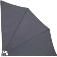
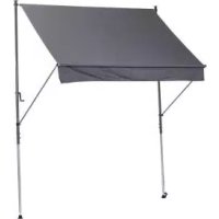
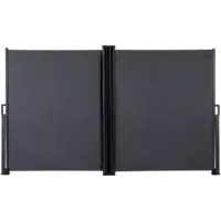
| Product type | Outdoor crank awning |
| Dimensions (unfolded) | Approx. 300 x 225-275 cm (width x height) |
| Wind resistance class | 0 (wind < 20 km/h) |
| Maximum load (non-retractable parts) | 15 kg |
| Intended use | Balcony, terrace (domestic use) |
| Fabric material | Not specified (standard fabric) |
| Operation | Crank |
| Manufacturing date | 02/2019 |
| Care and cleaning | Clean with water, dry with a soft cloth. Do not use abrasive products. |
| Safety | Do not use if wind > 20 km/h; check for damage before use; do not let children climb; max load 15 kg. |
| Assembly | Requires at least 2 people; ceiling and floor mounting; tools not supplied. |
| Warranty | 3 years from date of purchase (material and manufacturing defects) |
| After-sales service (France) | 0800 919270 (toll-free); deltasport@lidl.fr |
| After-sales service (Belgium) | 070 270 171 (0.15 EUR/min); deltasport@lidl.be |
Frequently Asked Questions - IAN 296717 FLORABEST
User questions about IAN 296717 FLORABEST
0 question about this device. Answer the ones you know or ask your own.
Ask a new question about this device
Download the instructions for your Outdoor blind in PDF format for free! Find your manual IAN 296717 - FLORABEST and take your electronic device back in hand. On this page are published all the documents necessary for the use of your device. IAN 296717 by FLORABEST.
USER MANUAL IAN 296717 FLORABEST
DELTA-SPORT HANDELSKONITOR GMBH
Wergelurp € 0522397 Hungary
COPRANAY
[Unreadable]
02/2019
3.10504922
[Unreadable]
florabest
natural_image
Exterior view of a dark outdoor awning structure with metal legs and a website URL (no signage on the awning itself)KLEMMMARKISE
CLAMP AWNING
STORE D'EXTÉRIEUR
DE AT CH
KLEMMMARKISE
Gebrauchsanweisung
FR 85
STORE D'EXTÉRIEUR
Instructions for use
NL M
KLEMMARKIES
Gebruiksaonwijzing
②
UPÍNACÍ MARKÝZA
Návod k obsluze

M M O
Before reading, told out the illustration page and get to know all of the functions of your unit.
① ②
GS/IE Instructors and Safety Online Page 16
natural_image
Pure mechanical diagram showing a frame structure with arrows and a north indicator (no text or symbols)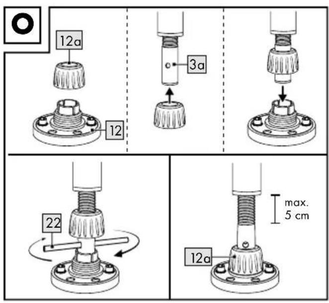
DE AT CH
WICHTIG, FÜR SPÄTERE BEZUGNAHME AUFBEWAHREN: SORGFÄLTIG LESEN!
GB IE
IMPORTANT: RETAIN FOR LATER REFERENCE; PLEASE READ CAREFULLY!
FR BE
IMPORTANT. LIRE ATTENTIVEMENT! A CONSERVER POUR RÉFÉRENCE ULTÉRIEURE.
NL BE
BELANGRIJK, BEWAREN OM LATER TE KUNNEN NASLAAN; ZORGVULDIG LEZEN!
PL
WAŻNE, PRZECHOWYWAĆ W CELU PÓŻNIEJSZEGO SKORZYSTANIA: PRZECZYTAĆ UWAŻNIE!
CZ
DŮLEŽITÉ, USCHOVEJTE PRO POZDĚJŠÍ ZHLÉDNUTÍ: ČTĚTE PEČLIVĚ!
SK
DÔLEŽITÉ, USCHOVAJTE KVÔLI NESKOR- ŠIEMU POUŽITIU: POZORNE PREČÍTAJTE!
DE AT CH
Preventing damage to the item 17
Important pre-installation information ..... 17 - 18
Suitable installation site 17-18
Suitable installation materials 18
Installation 18-20
Install ceiling bracket 18
Install floor bracket 18-19
Install posts 19
Install awning frame 19
Fix awning frame into the bracket .....19 - 20
Install front bar 20
Use 20
Storage, cleaning 20
Disposal 20
Notes on the guarantee and
service handling 20 - 21
NL BE
Leveringsomvang (afb. A) 30
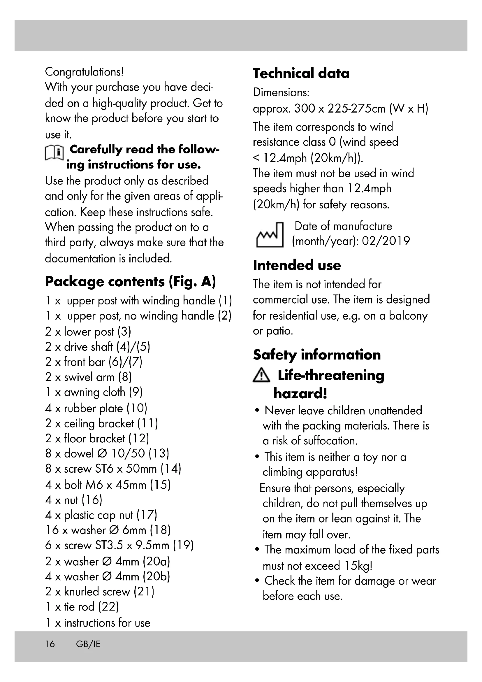
With your purchase you have decided on a high-quality product. Get to know the product before you start to use it.

Carefully read the following instructions for use.
Use the product only as described and only for the given areas of application. Keep these instructions safe. When passing the product on to a third party, always make sure that the documentation is included.
Package contents (Fig. A)
1 x upper post with winding handle (1)
1 x upper post, no winding handle (2)
2 x lower post (3)
2 x drive shaft (4)/(5)
2 x front bar (6)/(7)
2 x swivel arm (8)
1 x awning cloth (9)
4 x rubber plate (10)
2 x ceiling bracket (11)
2 x floor bracket (12)
8 x dowel ∅ 10/50 (13)
8 x screw ST6 x 50mm (14)
4 x bolt M6 x 45mm (15)
4 x nut (16)
4 x plastic cap nut (17)
16 x washer ∅ 6mm (18)
6 x screw ST3.5 x 9.5mm (19)
2 x washer ∅ 4mm (20a)
4 x washer ∅ 4mm (20b)
2 x knurled screw (21)
1 x tie rod (22)
1 x instructions for use
Technical data
Dimensions:
approx. 300 x 225-275cm (W x H)
The item corresponds to wind resistance class 0 (wind speed < 12.4mph (20km/h)).
The item must not be used in wind speeds higher than 12.4mph (20km/h) for safety reasons.

Date of manufacture (month/year): 02/2019
Intended use
The item is not intended for commercial use. The item is designed for residential use, e.g. on a balcony or patio.
Safety information

Life-threatening hazard!
- Never leave children unattended with the packing materials. There is a risk of suffocation.
- This item is neither a toy nor a climbing apparatus!
Ensure that persons, especially children, do not pull themselves up on the item or lean against it. The item may fall over. - The maximum load of the fixed parts must not exceed 15kg!
- Check the item for damage or wear before each use.
Ensure that the adapter plates have no external damage. Damaged adapter plates should be replaced.

Risk of injury!
- Please take care of your fingers when folding and unfolding. There is a risk of injury from crushing.
- The item may only be used under adult supervision and should not be used as a toy.
- Ensure the item is properly stabilised before using it.
- Keep open flames, BBQs and heat sources away from the item.
- Ensure that the item has been completely unclamped before use.
- Check the item for damage or wear before each use.
- Check that all parts have been installed properly before each use. Improper assembly can impair the item's safety and functionality.
- The item may not be used in adverse weather conditions such as strong winds, rain or snow.
• Take down the item if wind speeds higher than 12.4mph (20km/h) are expected (strong breeze, larger branches and trees move, and the wind is clearly audible). - You must not, under any circumstances, use the item as a shelter in storms.
-
Close the item if the wind picks up or in other adverse weather conditions.
-
Before opening or closing the item, ensure that there are no persons or objects in the opening or closing areas.
- The item offers protection from direct sunlight outdoors. Due to reflecting UV radiation, appropriate sunscreen products should still be used.
- Place the item on a flat, level surface.

Preventing damage to the item!
- Protect the item during extreme weather conditions, e.g. strong wind. Store the item in a sheltered area.
- Check the item regularly for visible signs of wear and damage. Check the screw connections regularly.
Important pre-installation information
WARNING! Before you start installing the clamping awning, measure the height between the floor and the ceiling.
WARNING! Assembling the item requires at least two people due to its size.
WARNING! As tools/machinery need to be used, manual skills are indispensable.
Suitable installation site
For ceiling installation, a concrete ceiling or a load-bearing wooden beam construction is suitable.
For floor installation, a concrete foundation or concrete slab of at least 50 × 50 × 5cm (L x W x D) is suitable.
Note: Alternative installation conditions must have the load-bearing capacity and strength inspected by a specialist.
Suitable installation materials
Before installing the item, the material must be determined.
If the installation site is load bearing, then the appropriate materials for fixing to it must be selected.
Fixing materials:
- Dowel ∅ 10/50 (13) and screw ST6 x 50mm (14) for concrete and load-bearing masonry.
- Screw ST6 x 50mm (14) for load-bearing wooden beam constructions.
Note: Please consult your local specialist store for fixing materials suitable for floor and ceiling brackets.
Installation
Install ceiling bracket
Important: Both ceiling brackets must be perfectly aligned and have a distance of exactly 288cm from each other (measured between the inner edge of both ceiling brackets) (Fig. F).
-
Place the ceiling bracket (11) in the desired position und mark 2 opposing holes with a pencil (Fig. B).
-
Using the correct tool, drill 2 holes in the marked places. Insert 1 dowel (13) into each hole (Fig. C).
- Place a rubber plate (10) on each ceiling bracket (11). Insert 2 screws (14) into a washer (18) each and screw the screws (14) in slightly to the rubber plates to fix them in place (Fig. D).
Note: This step makes it easier to fix the ceiling bracket to the ceiling later.
- Fit the ceiling bracket to the ceiling (Fig. E).
- Fit the second ceiling bracket as described in steps 1–4.
Install floor bracket
- Plumb the exact position of the floor bracket (12) with a cord (not included in the package contents). Mark the correct place and using a pencil mark 2 opposing holes (Fig. G).
Note: The floor bracket (12) must be positioned perpendicular to the ceiling bracket (11).
- Using the correct tool, drill 2 holes in the marked places. Insert 1 dowel into each hole (Fig. H).
- Place a rubber plate (10) on each floor bracket (12). Insert 2 screws (14) into a washer (18) each and screw the screws (14) in slightly to the rubber plates to fix them in place (Fig. I).
Note: This step makes it easier to fix the floor bracket to the floor later.
- Fit the floor bracket to the floor.
- Fit the second floor bracket as described in steps 1-4.
Important: Both floor brackets must be perfectly aligned and have a distance of exactly 288cm from each other (measured between the inner edge of both mounting brackets).
Install posts
To get the right length for the posts, they can be set at one of 9 positions (Fig. J).
- Connect each upper (1)/(2) and lower post (3) together (Fig. J).
- Fasten each upper (1)/(2) and lower post (3) with 2 screws (15) and washers (18). Fasten each screw (15) with a nut (16) and washer (18). Finally, put the plastic cap nuts (17) on each nut (Fig. K).
Install awning frame
-
Slot together both drive shaft poles (4)/(5) (Fig. L). The locking button must visibly and audibly click into place.
-
Push the drive shafts (4 + 5) through the tube in the awning cloth (9).
Note: Please note, the awning cloth (9) must be fixed directly onto the drive shaft (4 + 5) .
Note: Please note, that the lower pole's crease (front bar pole) must always face upwards during installation (Fig. L.).
- Adjust the driver (1a)/(2a) and the drive shaft (4 + 5) so that the screw hole and the driver nut are positioned above one another (Fig. M).
- Fasten the drive shaft to each driver (1a)/(2a).
Note: The drivers (1a)/(2a) must be fully positioned in the drive shaft on both sides.
- Fasten the awning cloth (9) and the drive shaft with the screws (19) and washers (20a) (Fig. M).
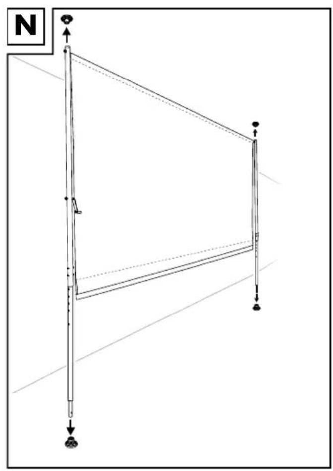
Fix awning frame into the bracket
Important: Installing the item requires at least two people, due to its size.
- Put the lock nut (12a) on the threaded spindle (3a) (Fig. O).
- Place the awning frame in the ceiling bracket (11) first.
- Then place the threaded spindle in the floor bracket (12) (Fig. O).
- Insert the tie rod (22) through the hole in the threaded spindle (3a) and turn it to securely mount the threaded spindle in the floor bracket (Fig. O).
Note: Please note the maximum extension length (max. 5cm) of the threaded spindle (3a).
- Turn the lock nut (12a) in the floor bracket (12) to fasten the threaded spindle (Fig. O).
Note: Please note that the threaded spindle (3a) may only be unscrewed by a max. 5cm (Fig. O).
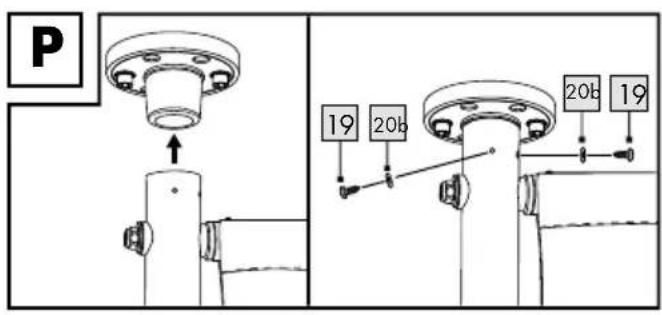
- Finally, fasten each ceiling bracket with 2 screws (19) and washers (20b) (Fig. P).
Install front bar
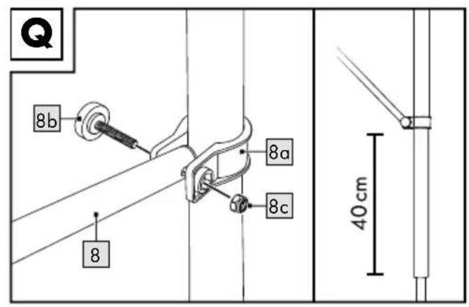
- Unscrew the knurled screw (8b) and the corresponding nut (8c) on the swivel arm bracket (8a) and place the bracket underneath the winding handle (Fig. Q).
Note: Ensure that both swivel arm brackets (8a) are fixed at the same height on the posts (approx. 40cm from the bottom edge of the upper post to the bottom edge of the bracket) (Fig. Q).
- Tightly screw the swivel arms back into each bracket (8a) with the knurled screws (8b) and the corresponding nuts (8c).
Note: The knurled screw (8b) points outwards.
-
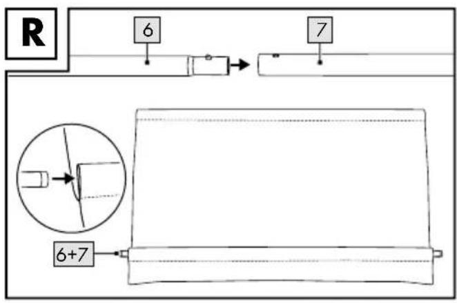
Insert the two front bars (6)/(7) into each other (Fig. R).
-
Push the front bar (6 + 7) into the front bar tube in the awning cloth (9) (Fig. R).
-
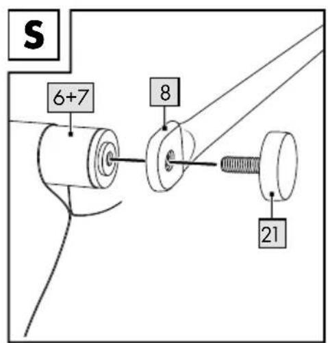
Fasten each swivel arm (8) onto the front bar (6 + 7) with the knurled screws (21) (Fig. S).
Use
Turn the winding handle to open or close the awning.
Storage, cleaning
Always store the item clean and dry at room temperature.
Clean only with water and wipe dry afterwards with a cleaning cloth.
IMPORTANT! Never clean the item with harsh cleansing agents.
Disposal
Dispose of the article and the packaging materials in accordance with current local regulations. Packaging materials such as foil bags are not suitable to be given to children. Keep the packaging materials out of the reach of children.

Dispose of the products and the packaging in an environmentally friendly manner.

The recycling code is used to identify various materials for recycling.
The code consists of the recycling symbol – which is meant to reflect the recycling cycle – and a number which identifies the material.
Notes on the guarantee and service handling
The product was produced with great care and under constant supervision.
You receive a three-year warranty for this product from the date of purchase.
Please retain your receipt.
The warranty applies only to material and workmanship and does not apply to misuse or improper handling. Your statutory rights, especially the warranty rights, are not affected by this warranty.
With regard to complaints, please contact the following service hotline or contact us by e-mail. Our service employees will advise as to the subsequent procedure as quickly as possible. We will be personally available to discuss the situation with you.
Any repairs under the warranty, statutory guarantees or through goodwill do not extend the warranty period. This also applies to replaced and repaired parts.
Repairs after the warranty are subject to a charge.
IAN: 296717
GB Service Great Britain
Tel.: 0800 404 7657
E-Mail: deltasport@lidl.co.uk
IE Service Ireland
Tel.: 1890 930 034
(0,08 EUR/Min., (peak))
(0,06 EUR/Min., (off peak))
E-Mail: deltasport@lidl.ie
Félicitations !


- KLEMMMARKISE
- CLAMP AWNING
- STORE D'EXTÉRIEUR
- DE AT CH
- NL BE
- Carefully read the following instructions for use.
- Package contents (Fig. A)
- Technical data
- Dimensions:
- Intended use
- Safety information
- Life-threatening hazard!
- Risk of injury!
- Preventing damage to the item!
- Important pre-installation information
- Suitable installation site
- Suitable installation materials
- Installation
- Install ceiling bracket
- Install floor bracket
- Install posts
- Install awning frame
- Fix awning frame into the bracket
- Install front bar
- Use
- Storage, cleaning
- Disposal
- Notes on the guarantee and service handling
Brand : FLORABEST
Model : IAN 296717
Category : Outdoor blind