
IAN 332809 - Outdoor blind FLORABEST - Free user manual and instructions
Find the device manual for free IAN 332809 FLORABEST in PDF.
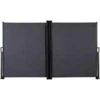
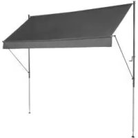
| Product Type | Outdoor awning (canopy) |
| Brand | Florabest |
| Model | IAN 332809 |
| Dimensions (width × height) | approx. 200 × 220 - 310 cm |
| Maximum arm extension depth | 150 cm |
| Wind resistance class | 0 (wind < 20 km/h) |
| Maximum permitted wind speed | 20 km/h |
| Operation | Manual crank |
| Intended use | Outdoor sun protection, private use (balcony, terrace) |
| Mounting surfaces | Ceiling (concrete or wooden beam) and floor (concrete slab) |
| Included fixing hardware | Anchors ∅10/50, screws ST6x50, screws M6x45, nuts, washers, caps |
| Warranty | 3 years (from date of purchase) |
| Maintenance | Clean with clear water and a soft cloth, air dry |
| Storage | Dry, clean place at room temperature |
| Assembly | Requires 2 people, tools not included (drill, wrench, screwdriver) |
| Safety instructions | Do not use in wind >20 km/h, do not allow children to climb, max load 15 kg on non-retractable parts |
| Included parts | 2 upper vertical tubes, 2 lower vertical tubes, 2 extension arms, 2 drive shafts, 1 canopy, 1 crank, supports, caps, screws |
| Canopy material | Not specified (likely coated polyester) |
| Weight | Not specified (estimated ~15-20 kg) |
| Manufacturing date | 12/2020 |
Frequently Asked Questions - IAN 332809 FLORABEST
User questions about IAN 332809 FLORABEST
0 question about this device. Answer the ones you know or ask your own.
Ask a new question about this device
Download the instructions for your Outdoor blind in PDF format for free! Find your manual IAN 332809 - FLORABEST and take your electronic device back in hand. On this page are published all the documents necessary for the use of your device. IAN 332809 by FLORABEST.
USER MANUAL IAN 332809 FLORABEST
natural_image
Exterior view of a modern office building (no signage)
CLAMP AWNING
DELTA SPORT HANDELSKONTOR OMBH
Weyburne • DC2207 Hurary
GERMANY
...
12/2020
Dr. 16 Sp. 34 N: K8/14/4
GB B NI
CLAMP AWNING
Assembly instructions
图 16
STORE D'EXTÉRIEUR
Notice de montage
12.4.22 20
DE AI CH
KLEMMMARKISE
Aufbauanleitung
PK
MARKISE
Monteringseiledning
NL ME
KLEM LUIEEL
Montagehandleiding

G8 Ⅲ Ⅳ
Before reading, told out the illustration page and got to know all of the functions of your crit.
(2)
GS/IE/N Assembly and safety information Page 10
natural_image
Pure technical line drawing of a vertical support structure without any text, numbers, or symbols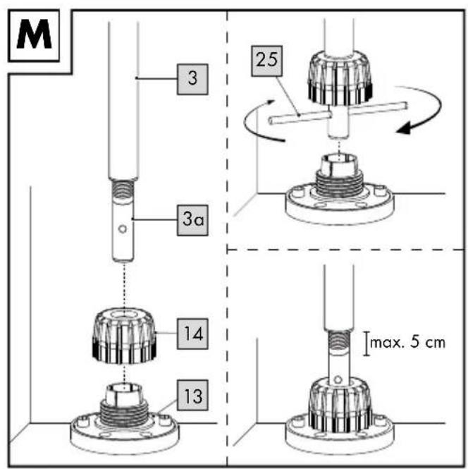
natural_image
Technical line drawing of a mechanical structure with vertical supports and a curved component, no text or symbols present.GB IE NI
IMPORTANT: RETAIN FOR LATER REFERENCE; PLEASE READ CAREFULLY!
DK
VIGTIG, GEM TIL SENERE BRUG: SKAL LÆSES GRUNDIGT!
FR BE
IMPORTANT. LIRE ATTENTIVEMENT! A CONSERVER POUR RÉFÉRENCE ULTÉRIEURE.
NL BE
BELANGRIJK, BEWAREN OM LATER TE KUNNEN NASLAAN; ZORGVULDIG LEZEN!
DE AT CH
WICHTIG, FÜR SPÄTERE BEZUGNAHME AUFBEWAHREN: SORGFÄLTIG LESEN!
GB IE NI
Package contents 10
Technical data 10
Intended use 10
Safety information 11-12
Life-threatening hazard 11
Risk of injury 11 - 12
Preventing damage to the product ..... 12
Important pre-installation information .... 12 - 13
Suitable installation site 12
Suitable installation materials ..... 12 - 13
Assembly 13-15
Installing the ceiling bracket 13
Installing the floor bracket 13 - 14
Installing the posts 14
Installing the awning frame 14
Fastening the awning frame into the bracket 14 - 15
Installing the drop arms and front bar .... 15
Use 15
Storage, cleaning 15
Disposal 16
Notes on the guarantee
and service handling 16
FR BE
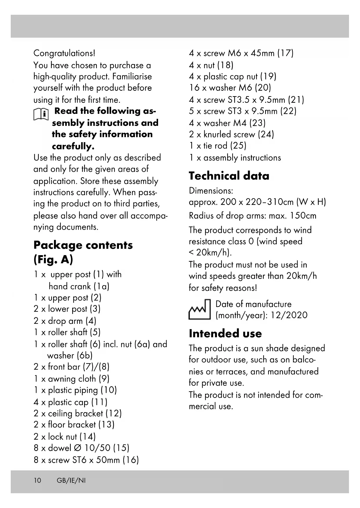
You have chosen to purchase a high-quality product. Familiarise yourself with the product before using it for the first time.

Read the following as- sembly instructions and the safety information carefully.
Use the product only as described and only for the given areas of application. Store these assembly instructions carefully. When passing the product on to third parties, please also hand over all accompanying documents.
Package contents (Fig. A)
1 x upper post (1) with hand crank (1a)
1 x upper post (2)
2 x lower post (3)
2 x drop arm (4)
1 x roller shaft (5)
1 x roller shaft (6) incl. nut (6a) and washer (6b)
2 x front bar (7)/(8)
1 x awning cloth (9)
1 x plastic piping (10)
4 x plastic cap (11)
2 x ceiling bracket (12)
2 x floor bracket (13)
2 x lock nut (14)
8 x dowel ∅ 10/50 (15)
8 x screw ST6 x 50mm (16)
4 x screw M6 x 45mm (17)
4 x nut (18)
4 x plastic cap nut (19)
16 x washer M6 (20)
4 x screw ST3.5 x 9.5mm (21)
5 x screw ST3 x 9.5mm (22)
4 x washer M4 (23)
2 x knurled screw (24)
1 x tie rod (25)
1 x assembly instructions
Technical data
Dimensions:
approx. 200 x 220-310cm (W x H)
Radius of drop arms: max. 150cm
The product corresponds to wind resistance class 0 (wind speed < 20km/h).
The product must not be used in wind speeds greater than 20km/h for safety reasons!

Date of manufacture
(month/year): 12/2020
Intended use
The product is a sun shade designed for outdoor use, such as on balconies or terraces, and manufactured for private use.
The product is not intended for commercial use.
Safety information
Life-threatening hazard!
- Never leave children unattended with the packaging materials.
There is a risk of suffocation.
- The product is not a toy or a climbing apparatus!
Ensure that persons, especially children, do not pull themselves up on the product or stand on it. The product can tip over.
- The maximum load of the non-retractable parts of the awning must not exceed 15kg!
- Check the product for damage or wear before each use. Only use the product if it is in perfect condition!
- Ensure that the plastic caps have no external damage. Defective plastic caps must be replaced.
- When installing on balconies or installation sites not at ground level, the floor and ceiling brackets must be fastened with suitable mounting materials in order to prevent the product from falling.
- Because of the risk of falling, make sure that the person installing the product is sufficiently secured with a harness.
Risk of injury!
- Mind your fingers in particular when retracting and extending the product. There is a risk of injury from crushing.
- The product may only be used under adult supervision and must not be used as a toy.
- Ensure the product is properly stabilised before using it.
- Keep open flames, barbecues, and patio heaters away from the product.
- Check that all parts have been properly assembled before each use.
- Improper installation can impair the product's safety and functionality.
- The product must not be used in adverse weather conditions such as strong winds, rain or snow.
- Retract the product if wind speeds higher than 20km/h are expected (strong breeze, larger branches and trees move, and the wind is clearly audible).
- Never use the product as shelter during storms.
- Close the product if the wind picks up or in other adverse weather conditions.
- Before opening or closing the product, ensure that there are no persons or objects in the opening or closing areas.
- The product offers protection from direct sunlight outdoors. Due to reflecting UV radiation, appropriate sunscreen products should still be used.
- Place the product on a flat, level surface.
- Check regularly to make sure all screws are tight!
- The manufacturer accepts no liability for accidents which occur as a result of ignoring the safety information above or due to improper handling.
⚠️ Preventing damage to the product!
- Secure the product during extreme weather conditions, e.g. strong winds. Store the product in a sheltered area.
Important pre-installation information
WARNING! To ensure optimal stability of the product, we recommend fastening the floor and ceiling brackets, especially on balconies or installation sites that are not at ground level. If the product is not screwed to the floor and ceiling, the manufacturer is absolved of all liability.
WARNING! Before you begin installing the product, measure the height between the floor and the ceiling.
WARNING! Installing the product requires at least two people due to its size.
WARNING! As tools/machinery need to be used, manual skills are indispensable.
Suitable installation site
For ceiling installation, a concrete ceiling or a load-bearing wooden beam structure is suitable.
For floor installation, a concrete foundation or concrete slab of at least 50 × 50 × 5cm (L x W x D) is suitable.
Note: if you attach the product to a wooden beam structure, you must firmly fasten the product to it as wood warps depending on the temperature and humidity. Enquire at a specialist retailer about suitable installation materials.
Note: alternative installation conditions must be checked by a specialist company for their load-bearing capacity and durability.
Suitable installation materials
Before installing the product, the installation material must be determined.
If the installation surface is load-bearing, the appropriate installation materials for fastening the product must be selected.
Fastening materials:
- Dowel ∅ 10/50 (15) and screw ST6 x 50mm (16) for concrete and load-bearing masonry.
- Screw ST6 x 50mm (16) for load-bearing wooden beam structures.
Note: inquire at a specialist retailer about suitable installation materials for the floor and ceiling brackets.
Assembly
To assemble the product you will need the following tools (not included in the package contents): a suitable drill, measuring tape, a cross-head screwdriver, a spanner and a hex key.
WARNING! Because of the risk of falling, make sure that the person installing the product is sufficiently secured with a harness.
Note: to ensure optimal stability of the product, we recommend fastening the floor and ceiling brackets.
Installing the ceiling bracket
Important: both ceiling brackets must be perfectly aligned and have a distance of exactly 190cm from each other (measured between the inner drill holes of both ceiling brackets) (Fig. E).
Place the ceiling bracket (12) in the desired position and mark 2 holes opposite each other with a pencil (Fig. B).
- Using the appropriate tool, drill 2 holes in the marked places. Insert 1 dowel (15) into each hole (Fig. C).
Note: use other dowels and screws if required for the installation surface.
-
Place a plastic cap (11) onto each ceiling bracket (12) and insert 2 screws (16) through each washer (20) (Fig. D).
-
Mount the ceiling bracket onto the ceiling.
-
Mount the second ceiling bracket as described in steps 1-4.
Installing the floor bracket
- Plumb the exact position of the floor bracket (13) with a cord (not included in the package contents). Mark the correct places and, using a pencil, mark 2 holes opposite each other (Fig. F).
Note: the floor bracket (13) must be positioned perpendicular to the ceiling bracket (12).
- Using the appropriate tool, drill 2 holes in the marked places. Insert 1 dowel (15) into each hole (Fig. G).
Note: if necessary, use other dowels and screws if required for the mounting surface.
- Place a plastic cap (11) onto each floor bracket (13) and insert 2 screws (16) through each washer (20) (Fig. H).
- Mount the floor bracket onto the floor.
- Mount the second floor bracket as described in steps 1-4.
Important: the floor brackets must be perfectly aligned and have a distance of exactly 190cm from each other (measured between the inner drill holes of both floor brackets).
Installing the posts (Fig. I)
There are 18 adjustment options for setting the correct length of the posts.
- Connect each upper (1)/(2) and lower post (3) at the appropriate length.
- Fasten each upper (1)/(2) and lower post (3) with 2 screws (17) and washers (20). Fasten each screw (17) with a nut (18) and washer (20). Then place a plastic cap (19) on each nut.
Installing the awning frame
- Slot both drive shaft poles (5)/(6) together (Fig. J).
- Fasten the drive shaft (5 + 6) with 4 screws (22).
-
Slot both front bars (7)/(8) together (Fig. J). The locking button must visibly and audibly click into place.
-
Run the plastic piping (10) through the narrower tunnel of the awning cloth (9).
- Insert the awning cloth with plastic piping into the drive shaft (5 + 6) as shown.
Note: make sure that the bottom fold of the tunnel (front bar tunnel) is always facing upward during installation.
- Insert the front bar (7 + 8) into the front bar tunnel in the awning cloth (9).
- Place the end of the roller shaft (5) on the catch (2a) of the post (2) (Fig. K).
Note: the catch (2a) must be completely inside the roller shaft (5).
- Remove the pre-mounted nut (6a) and washer (6b) from the roller shaft (6).
- Insert the end of the roller shaft (6) into the post (1). Use the nut (6a) and washer (6b) to fasten it (Fig. K).
Note: make sure that the bolt on the roller shaft (6) is properly aligned.
- Fasten the roller shaft (5) with 1 screw (22) (Fig. K).
Fastening the awning frame in the bracket
Important: assembling the product requires at least two people due to its size.
- First insert the awning frame into the ceiling brackets (Fig. L).
- Place the lock nut (14) onto the threaded spindle (3a) (Fig. M).
- Insert the tie rod (25) through the hole in the threaded spindle (3a) and turn it to change the height of the post (Fig. M).
Note: please note the maximum extension length (max. 5cm) of the threaded spindle (3a).
- Turn the lock nut (14) in the floor bracket (13) to fasten the threaded spindle (Fig. M).
Note: please note that the threaded spindle (3a) may only be unscrewed by no more than 5cm (Fig. M).
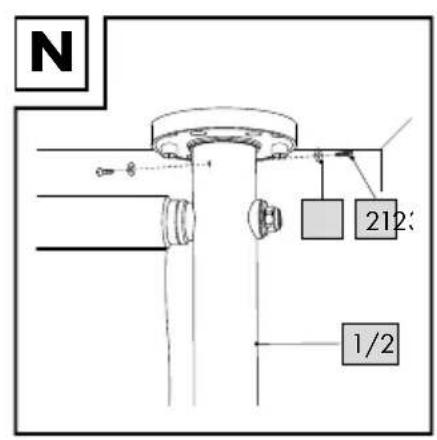
- Finally, fasten the posts on each ceiling bracket with 2 screws (21) and washers (23) (Fig. N).
Note: for easier installation, drill two holes into each ceiling bracket before fastening the posts.
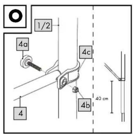
Installing the drop arms and front bar
- Unscrew the knurled screw (4a), the corresponding nut (4b) and the drop arm bracket (4c) from each drop arm (4).
- Place the drop arm bracket (4c) on a post (1/2) (Fig. O).
Note: ensure that both drop arm brackets (4c) are fixed at the same height on the posts (approx. 40cm from the bottom edge of the upper post to the bottom edge of the drop arm bracket).
- Tightly screw the drop arms back into each drop arm bracket (4c) with the knurled screws (4a) and the corresponding nuts (4b).
Note: the knurled screw (4a) points outwards.
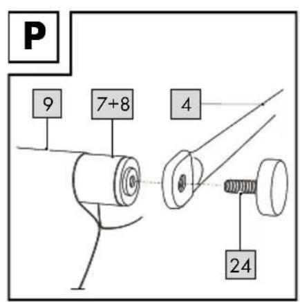
- Fasten each drop arm (4) onto the front bar (7 + 8) with the knurled screws (24) (Fig. P).
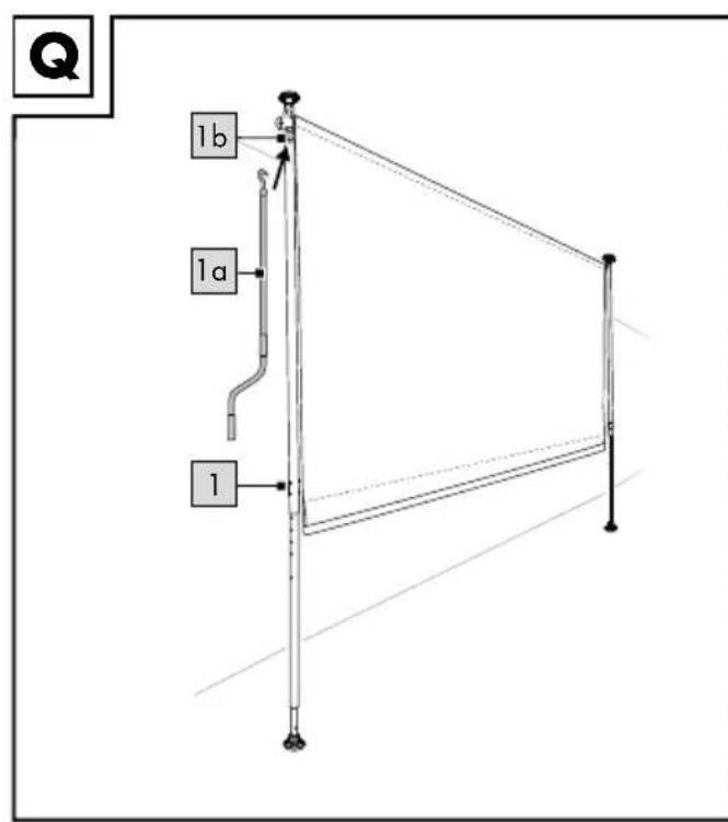
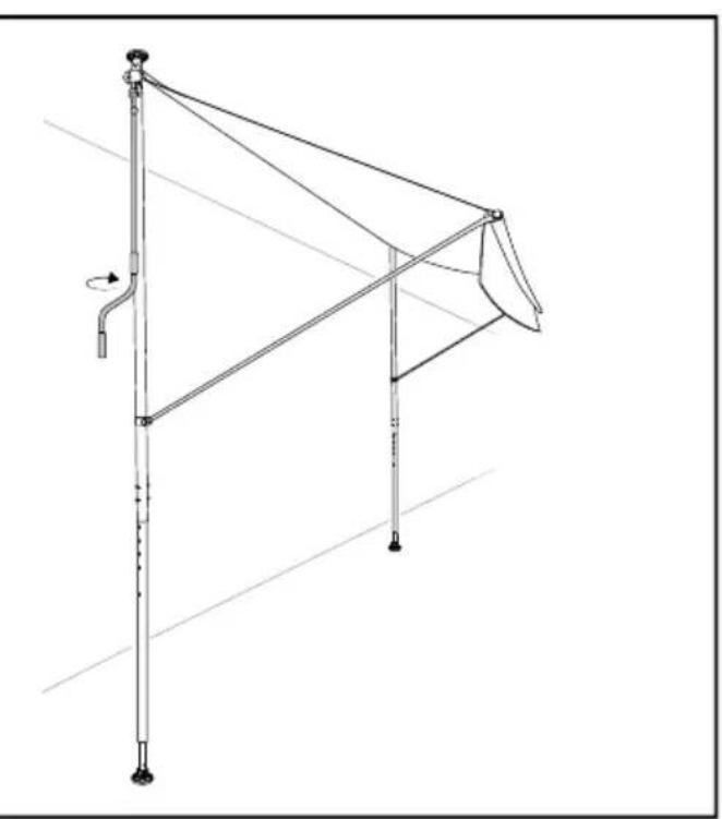
Use (Fig. Q)
- Hook the hand crank (1a) into the crank lug (1b) of the upper post (1).
- Turn the hand crank (1a) to open or close the product.
- Remove the hand crank (1a) after each use and store it in a secure location.
Storage, cleaning
When not in use, always store the product clean and dry at room temperature.
Clean only with water and wipe dry afterwards with a cloth.
IMPORTANT! Never clean the product with harsh cleaning agents.
Leave the product open to dry.
Disposal
Dispose of the article and the packaging materials in accordance with current local regulations. Packaging materials such as foil bags are not suitable to be given to children. Keep the packaging materials out of the reach of children.

Dispose of the products and the packaging in an environmentally friendly manner.

The recycling code is used to identify various materials for recycling. The code consists of the recycling symbol – which is meant to reflect the recycling cycle – and a number which identifies the material.
Notes on the guarantee and service handling
The product was produced with great care and under constant supervision. You receive a three-year warranty for this product from the date of purchase. Please retain your receipt.
The warranty applies only to material and workmanship and does not apply to misuse or improper handling. Your statutory rights, especially the warranty rights, are not affected by this warranty.
With regard to complaints, please contact the following service hotline or contact us by e-mail.
Our service employees will advise as to the subsequent procedure as quickly as possible. We will be personally available to discuss the situation with you.
Any repairs under the warranty, statutory guarantees or through goodwill do not extend the warranty period. This also applies to replaced and repaired parts. Repairs after the warranty are subject to a charge.
IAN: 352928_2007
GB Service Great Britain
Tel.: 0800 404 7657
E-Mail: deltasport@lidl.co.uk
IE Service Ireland
NI Tel.: 1890 930 034
(0,08 EUR/
Min., (peak))
(0,06 EUR/
Min., (off peak))
E-Mail: deltasport@lidl.ie
Hjertelig tillykke!


- CLAMP AWNING
- IMPORTANT: RETAIN FOR LATER REFERENCE; PLEASE READ CAREFULLY!
- VIGTIG, GEM TIL SENERE BRUG: SKAL LÆSES GRUNDIGT!
- IMPORTANT. LIRE ATTENTIVEMENT! A CONSERVER POUR RÉFÉRENCE ULTÉRIEURE.
- BELANGRIJK, BEWAREN OM LATER TE KUNNEN NASLAAN; ZORGVULDIG LEZEN!
- WICHTIG, FÜR SPÄTERE BEZUGNAHME AUFBEWAHREN: SORGFÄLTIG LESEN!
- GB IE NI
- FR BE
- Read the following as- sembly instructions and the safety information carefully.
- Package contents (Fig. A)
- Technical data
- Intended use
- Safety information
- Life-threatening hazard!
- Risk of injury!
- ⚠️ Preventing damage to the product!
- Important pre-installation information
- Suitable installation site
- Suitable installation materials
- Assembly
- Installing the ceiling bracket
- Installing the floor bracket
- Installing the posts (Fig. I)
- Installing the awning frame
- Fastening the awning frame in the bracket
- Installing the drop arms and front bar
- Use (Fig. Q)
- Storage, cleaning
- Disposal
- Notes on the guarantee and service handling
Brand : FLORABEST
Model : IAN 332809
Category : Outdoor blind