MFK 700 EQB - Router FESTOOL - Free user manual and instructions
Find the device manual for free MFK 700 EQB FESTOOL in PDF.

| Product type | Router / trimmer |
| Brand | Festool |
| Model | MFK 700 EQB |
| Power consumption | 720 W |
| No-load speed (min - max) | 10,000 - 26,000 rpm |
| Speed control | Continuous via wheel |
| Tool holder (collet) | 8 mm (option: 6 mm, 1/4\") |
| Max cutter diameter | 26 mm / 1\" |
| Extraction connection | 27 mm |
| Weight (according to EPTA 01:2014) | 2.0 kg |
| Protection class | II (double insulation) |
| Constant speed | Yes, electronic regulation |
| Anti-restart protection | Yes, built-in |
| Thermal fuse | Yes, reduces power on overheating |
| Sound pressure level (LpA) | 81 dB(A) (K=1.5 dB) |
| Sound power level (LwA) | 92 dB(A) (K=1.5 dB) |
| Vibration emission value (ah) | < 2.5 m/s² (K=1.5 m/s²) |
| Routing table | For edge banding, removable |
| Brake for ball bearing | Removable, 2 heights |
| Spindle lock | Yes, for tool change |
| Included accessories (depending on country) | Collets (8 mm, 6 mm, 1/4\"), open-ended wrench |
| Maintenance | Clean ventilation slots, automatic cut-off carbon brushes |
| Repairability | Genuine Festool spare parts, authorized service center |
| Intended use | Edge routing of wood, plastic and similar materials |
| Power supply | Mains, 220-240 V / 50-60 Hz (120 V / 60 Hz for North America) |
Frequently Asked Questions - MFK 700 EQB FESTOOL
User questions about MFK 700 EQB FESTOOL
0 question about this device. Answer the ones you know or ask your own.
Ask a new question about this device
Download the instructions for your Router in PDF format for free! Find your manual MFK 700 EQB - FESTOOL and take your electronic device back in hand. On this page are published all the documents necessary for the use of your device. MFK 700 EQB by FESTOOL.
USER MANUAL MFK 700 EQB FESTOOL
MFK 700 EQ MFK 700 EQ/B
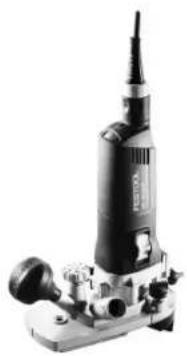
natural_image
Black and white photo of a precision power tool with no visible text or symbols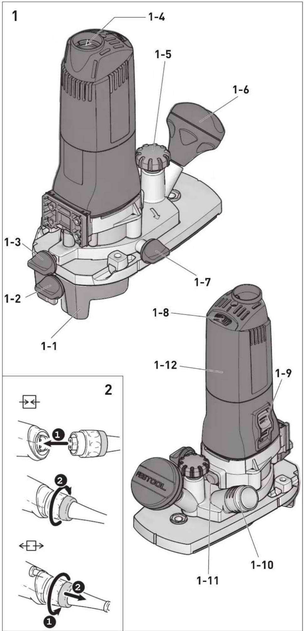
natural_image
Technical line drawing of a mechanical component with a plus sign and crosshair (no text or symbols)7
natural_image
Technical line drawing of a mechanical device with no visible text or symbols
natural_image
Technical line drawing of a mechanical device with no visible text or symbolsKantenfräse
Edge router
Affleureuse
Seriennummer *
Serial number *
N° de série *
(T-Nr.)
MFK 700 EQ 10488470,10488466
de EU-Konformitätserklärung. Wir erklären in alleiniger Verantwortung, dass dieses Produkt mit allen relevanten Anforderungen folgender EU-Richtlinien übereinstimmt, und folgende Normen oder normative Dokumente zugrunde gelegt wurden:
en EU Declaration of Conformity. We declare under sole responsibility that this product complies with all the relevant requirements in the following EU Directives, and following standards and normative documents were applied:
fr Déclaration de conformité de l'UE. Nous déclarons, sous notre seule responsabilité, que ce produit satisfait à toutes les exigences pertinentes des directives UE suivantes et repose sur les normes ou documents normatifs suivants :
es Declaración UE de conformidad. Declaramos bajo nuestra responsabilidad que este producto cumple todos los requisitos relevantes de las siguientes directivas de la UE y que se han tomado como base las siguientes normas o documentos normativos:
it Dichiarazione di conformità UE. Dichiariamo sotto nostra unica responsabilità che il presente prodotto sia conforme a tutti i requisiti di rilevanza definiti dalle seguenti Direttive UE e che siano stati applicati le seguenti norme o i seguenti documenti normativi:
nl EU-conformiteitsverklaring. Wij verklaren en stellen ons ervoor verantwoordelijk dat dit product volledig voldoet aan alle volgende EU-richtlijnen en volgende normen of normatieve documenten daaraan ten grondslag gelegd werden:
SV EU-försäkran om överensstämmelse. Vi för- klarar på eget ansvar att denna produkt uppfyller alla relevanta krav enligt följande EU-direktiv och baseras på följande normer eller normgivande dokument:
fi EU-vaatimustenmukaisuusvakuutus. Vakuutamme yksinomaisella vastuulla, että tämä tuote täyttää seuraavien EU-direktiivien kaikki olennaiset vaatimukset ja se on seuraavien standardien tai standardiasia-kirjojen mukainen:
da EU-overensstemmelseserklæring. Vi erklærer med eneansvar, at dette produkt er i overensstemmelse med alle relevante krav i følgende EU-direktiver, og at følgende standarder eller normative dokumenter danner grundlag for det:
nb EU-samsvarserklæring. Vi erklærer under eneansvar at dette produktet oppfyller alle relevante krav i følgende EU-direktiver og at følgende standarder eller normative dokumenter er blitt lagt til grunn:
Head of Product Development

Ralf Brandt
Head of Product Conformity
MFK 700 EQ 10488470, 10488466
We as the manufacturer declare under our sole responsibility that this product(s) fulfill(s) all the relevant provisions of the following UK Regulations and are manufactured in accordance with the following designated standards:
S.I. 2008/1597
S.I. 2016/1091
S.I. 2012/3032
BS EN 62841-1:2015
BS EN 62841-2-17:2017
BS EN 55014-1:2017
BS EN 55014-2:2015
BS EN IEC 61000-3-2:2019
BS EN 61000-3-3:2013
BS EN IEC 63000:2018

on behalf of and in name of
Festool GmbH
Wertstr. 20, 73240 Wendlingen, GERMANY
Place and date of declaration: Wendlingen, 07.10.2021

Markus Stark
Head of Product Development

Ralf Brandt
Head of Product Conformity
^11 in the specified serial number range (S-Nr.) from 40000000 - 49999999
Inhaltsverzeichnis
1 Symbols....13
2 Safety warnings....13
3 Intended use 14
4 Technical data.... 14
5 Parts of the device....14
6 Commissioning....15
7 Settings....15
8 Working with the electric power tool......16
9 Service and maintenance....16
10 Accessories.... 17
11 Environment....17
12 General information....17
1 Symbols

Warning of general danger

Warning of electric shock

Read the operating instructions and safety instructions.

Wear ear protection.

Wear a dust mask.

Wear protective gloves.

Wear protective goggles.

Disconnecting the mains power cable

Connecting the mains power cable

Safety class II

Do not dispose of it with domestic waste.

CE marking: Confirms the conformity of the power tool with the European Community directives.

Tip or advice

Handling instruction

UKCA marking: The United Kingdom Conformity Assessed symbol is a marking for products being placed on the market in the United Kingdom. It is a manufacturers indication that the product is in conformance with the relevant regulations in the UK.
2 Safety warnings
2.1 General power tool safety warnings

WARNING! Read all safety warnings, instructions, illustrations and specifications provided with this power tool. Failure to follow all instructions listed below may result in electric shock, fire and/or serious injury.
Save all warnings and instructions for future reference.
The term "power tool" in the warnings refers to your mains-operated (corded) power tool or battery-operated (cordless) power tool.
2.2 Machine-specific safety notices
- Hold the power tool by insulated gripping surfaces only, because the cutter may contact its own cord. Cutting a "live" wire may make exposed metal parts of the power tool "live" and could give the operator an electric shock.
- Use clamps or another practical way to secure and support the workpiece to a stable platform. Holding the work by your hand or against the body leaves it unstable and may lead to loss of control.
- Do not clamp tools with an unsuitable shank diameter in the clamping collet.
- Operate power tool only with properly installed guide table and extraction hood
- Only cutters provided by Festool for this purpose may be mounted on the power tool. The use of other cutters is prohibited due to the increased risk of injury.
- Only use tools that meet standard EN 847-1. All Festool routing tools fulfil these requirements.
- The clamping collet and locking nut must not show any signs of damage
- Do not use cracked or deformed router bits.
- Ensure that the router bit is seated firmly and that it runs perfectly.
- The maximum rotational speed specified on the tool must not be exceeded or the rotational speed range must be observed.
English
Accessories that rotate faster than the permissible level can rupture.
- Do not work on the power tool if its electronics are defective as this may lead to excessive speeds. You can tell if the electronics are defective if there is no smooth start-up, if it is not possible to regulate the speed and in the event of generation of smoke or the smell of burning from the machine.


Wear suitable personal protective equipment: Ear protection, protective goggles, dust mask for work that generates dust, protective gloves for working with rough materials and for changing tools.
- Only for AS/NZS: The tool shall always be supplied via residual current device with a rated residual current of 30 mA or less.
2.3 Emission levels
The levels determined in accordance with EN 62841 are typically:
Sound pressure level L _PA = 81 dB(A)
Sound power level L _WA = 92 dB(A)
Uncertainty K = 1,5 dB


CAUTION
Noise generated when working Risk of damage to hearing
▶ Use ear protection.
Vibration emission level a_h (vector sum for three directions) and uncertainty K measured in accordance with EN 62841:
$$ a _ {h} < 2, 5 m / s ^ {2} $$
$$ K = 1, 5 \mathrm{m} / \mathrm{s} ^ {2} $$
The specified emission levels (vibration, noise)
- are used to compare machines.
- They are also used for making preliminary estimates regarding vibration and noise load during operation.
- They represent the primary applications of the power tool.

CAUTION
The emission values may deviate from the specified values. This is dependent on how the tool is used and the type of workpiece being machined.
▶ The actual load during the entire operating cycle must be evaluated.
▶ Depending on the actual load, suitable protective measures must be defined in order to protect the operator.
3 Intended use
The edge router with router table for edging must be used for its intended purpose, i.e. cutting edges made from wood, plastic and similar materials.

The user is liable for improper or non-in-tended use.
4 Technical data
Edge router
Power 720 W
Speed 10,000–26,000 rpm
Max. speed (no-load) 26,000 rpm
Tool holder 8 mm
(optional: 6 mm, 1/4")
Max. routing diameter 26 mm/1"
Connection dia. d/e 27 mm
Weight as per EPTA procedure 2.0 kg 01:2014:
5 Parts of the device
[1-1] Router stop
[1-2] Locking for ball bearing brake
[1-3]/[1-7] Locking for routing depth
[1-4] Plug-it connection
[1-5] Routing depth setting
[1-6] Handle, locking for routing depth
[1-8] Speed control
[1-9] On/off switch
[1-10] Extractor connector
[1-11] Spindle lock
[1-12] Gripping surface
The specified illustrations appear at the beginning of the Operating Instructions.
6 Commissioning

WARNING
Unauthorised voltage or frequency.
Risk of accidents
▶ The mains voltage and the frequency of the power source must correspond to the specifications on the name plate.
▶ In North America, only Festool machines with the voltage specifications 120 V/60 Hz may be used.

CAUTION
Heating of the Plug it connection if bayonet fitting is not completely locked
Risk of burns
▶ Before switching on the power tool, make sure that the bayonet fitting at the mains cable is closed fully and locked.
Connecting and detaching the mains power cable - see Fig. 2.
6.1 Switching on/off
The switch [1-9] serves as an on/off switch (I = ON, 0 = OFF).
7 Settings

WARNING
Risk of injury, electric shock
▶ Always disconnect the mains plug from the socket before performing any work on the machine.
7.1 Electronics
Constant speed
The preselected motor speed is kept constant through electronic control. This ensures a uniform speed even when under load.
Speed control
You can use the adjusting wheel [1-8] to continuously adjust the speed within the speed range (see Section Technical data). This enables you to optimise the speed to suit the respective material. Please also note the specifications on the tools.
Scorch or melt marks on the material can be prevented through reducing the speed.
Temperature cut-out
The power supply is restricted and the speed reduced if the motor exceeds a certain temperature. The power tool continues operating at reduced power to allow the ventilator to cool the motor quickly. The power tool starts up again automatically once the motor has cooled sufficiently.
Restart protection
The built-in restart protection prevents the power tool from starting up again automatically if the power is disconnected when the on/off switch is pressed. In this case, the power tool must be switched off and then switched back on again.
Due to the built-in restart protection, the power tool cannot be switched on and off via an external switch module.
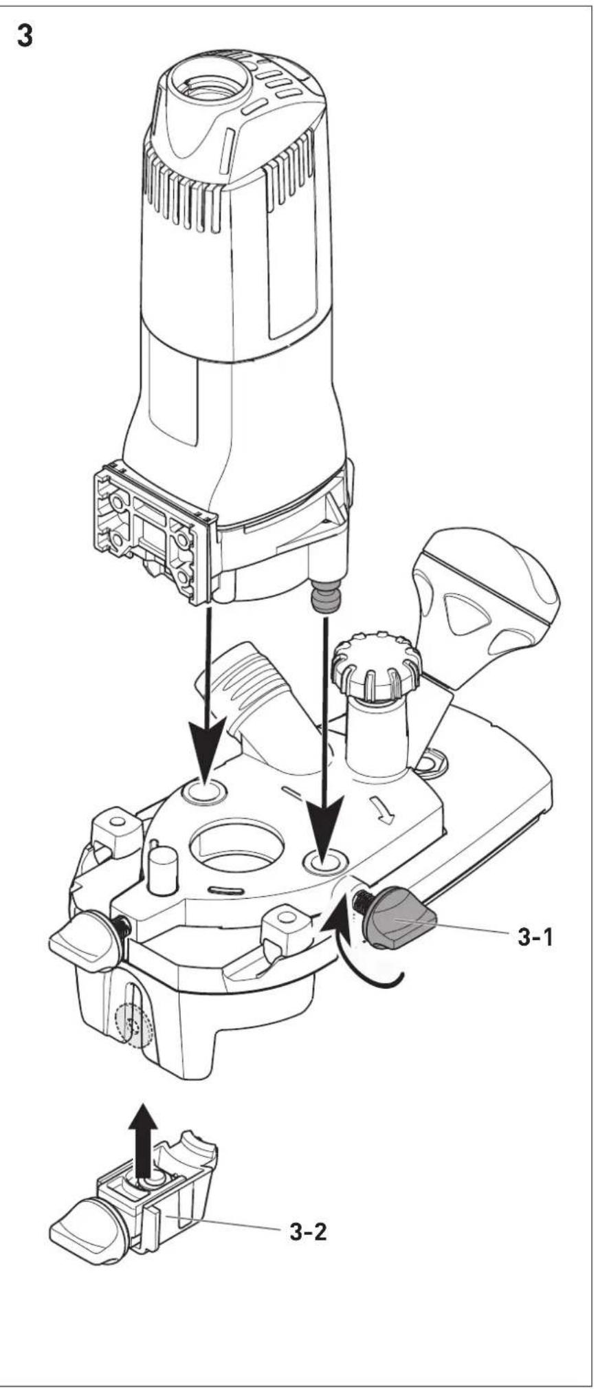
7.2 Replacing router table
The router table for edging is optimally designed for cutting protruding edging thanks to the large contact surface.
▶ Slide router table onto mounting bolts of machine [3].
▶ If nec., remove ball bearing brake [3-2].
▶ Secure locking for router table [3-1].
▶ If nec., insert ball bearing brake [3-2] .
Removal in reverse order.
7.3 Changing tools

CAUTION
Risk of injury from hot and sharp insertion tool
▶ Do not use any blunt or faulty insertion tools.
▶ Wear protective gloves when handling an insertion tool.
Before replacing the cutter remove the router table.
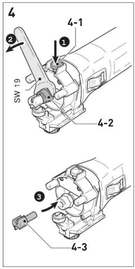
Removing the tool
▶ Push spindle lock [4-1].
▶ Slacken union nut [4-2] using open ended spanner (SW 19) until the tool can be removed.
▶ Release spindle lock [4-1].
Inserting the tool
- Position the cutter [4-3] as far as possible, at least as far as the marking at the cutter shaft, into the open clamping collet.
▶ Push spindle lock [4-1] .
English
▶ Tighten union nut [4-2] using open ended spanner (SW 19).
▶ Release spindle lock [4-1] .
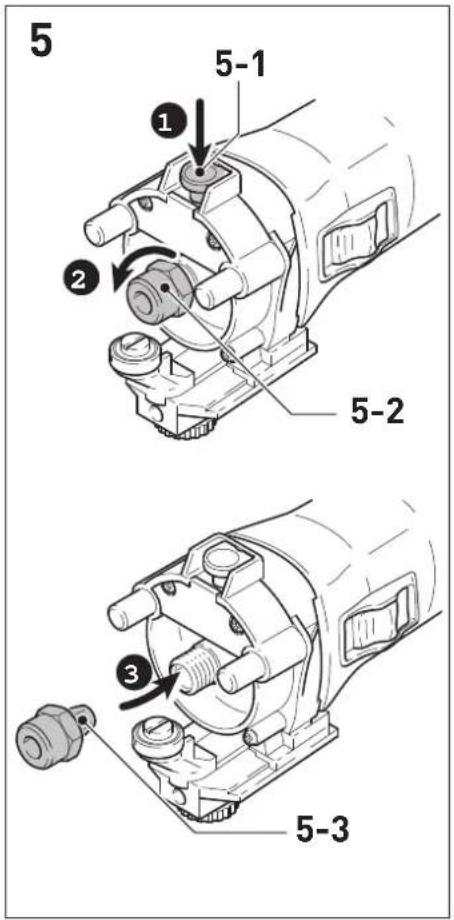
7.4 Replacing clamping collet
Only suitable tools can be used with the supplied collets. Collets with 8 mm, 6 mm and 1/4" (6.35 mm) can be used.
▶ Push spindle lock [5-1] .
▶ Unscrew union nut [5-2] fully.
▶ Release spindle lock [5-1] .
- Remove union nut together with the clamping collet [5-3] from the spindle. Never separate the union nut and clamping collet! They form one unit.
- Insert another clamping collet with union nut into the spindle.
▶ Gently turn union nut. Do not tighten union nut if there is no cutter inserted!
7.5 Setting the routing depth
▶ Slacken locking mechanisms for routing depth [1-3] + [1-6].
▶ Adjust desired routing depth at the routing depth setting [1-7].
▶ Secure locking mechanisms for routing depth [1-3] + [1-6].
7.6 Dust extraction

WARNING
Heath hazard posed by dust
▶ Always work with an extractor.
▶ Comply with national regulations.
A Festool mobile dust extractor with an extraction hose diameter of 27 mm should be connected at the extractor connector [1-10].
CAUTION! If an anti-static suction hose is not used, static charge may occur. The user may receive an electric shock and the electronics of the power tool may be damaged.
8 Working with the electric power tool
When working on the machine, observe all of the safety warnings that are listed at the start as well as the following rules:
- Always secure the workpiece in such a way that it cannot move during machining.
-
Hold the machine with two hands – one on the motor housing and one on the gear head or on the additional handle [1-6] – to ensure safe guidance.
-
Adjust the feed speed to the router diameter and the material. Work with a constant feed speed.
- Only guide the power tool towards the workpiece when it is switched on.
- Wait until the power tool has come to a complete halt before placing it down. The insertion tool can get caught and lead to a loss of control of the power tool.
- Make sure that the router table is firmly tightened before routing.
- When routing, ensure that the power tool's feed direction is the same as the tool's cutting direction.
8.1 Guide types
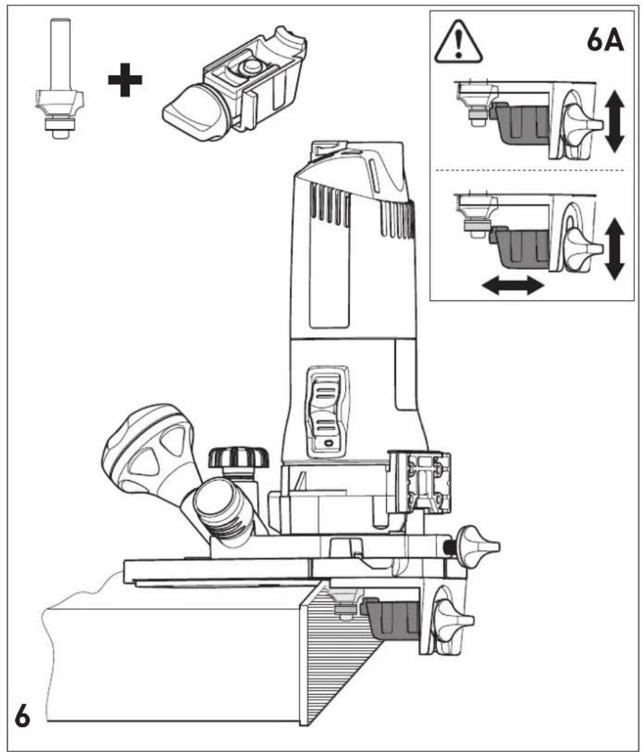
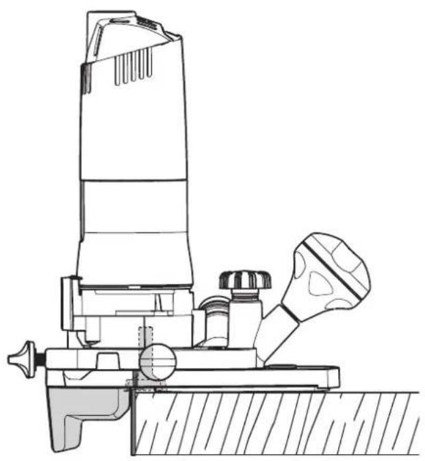
Routing with ball bearing guide [6]
When routing with cutters with a ball bearing guide the ball bearing brake must be inserted in the edge router. The edge router is guided so that the ball bearing guide of the cutter rolls between the brake and edging.
Adapt height of the brake to the height of the ball bearing guide - 2 stages [6A].
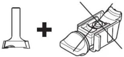
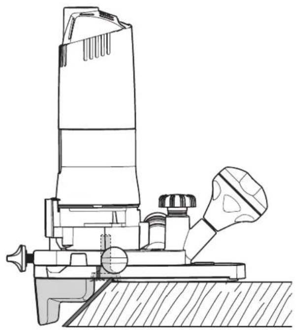
Routing with plane cutter [7]
The ball bearing brake is not used when routing with plane cutters. Guide edge router so that the stop of the router table is at the edging - also possible at diagonal edges.
9 Service and maintenance

WARNING
Risk of injury, electric shock
▶ Always pull the mains plug from the socket before performing any servicing and maintenance work.
▶ All maintenance and repair work which requires the motor housing to be opened should always be carried out by an authorised service workshop.

Customer service and repairs must only be carried out by the manufacturer or service workshops. Find the nearest address at: www.festool.co.uk/service
Always use original Festool spare parts. Order no. at: www.festool.co.uk/service
▶ Damaged safety devices and components must be repaired or replaced in a recognised specialist workshop, unless otherwise indicated in the operating instructions.
The tool is equipped with special self-disconnecting carbon brushes. If they wear out, the power supply is disconnected automatically and the tool stops.
▶ To ensure constant air circulation, always keep the cooling air openings in the motor housing clean and free of blockages.
10 Accessories
The order numbers of the accessories and tools can be found in the Festool catalogue or on the Internet at "www.festool.com".
11 Environment

Do not dispose of the device in the household waste! Recycle devices, accessories and packaging. Observe applicable national regulations.
EU only: In accordance with the European Directive on waste electrical and electronic equipment and implementation in national law, used power tools must be collected separately and handed in for environmentally friendly recycling.
Information on REACH: www.festool.com/reach
12 General information
Imported into the UK by
Festool UK Ltd
1 Anglo Saxon Way
Bury St Edmunds
IP30 9XH
Great Britain
Sommaire
Peso de acordo com EPTA-2,0 kg Procedure 01:2014: