
90 F - Boiler Baxi - Free user manual and instructions
Find the device manual for free 90 F Baxi in PDF.
| Brand | Baxi |
| Model | 90 F |
| Product Type | Wall-mounted gas condensing boiler |
| Power Supply | 230 V ~ 50/60 Hz |
| Power Consumption (AVS 75 module) | 4 VA |
| Fuse | max. 10 AT |
| Number of Heating Circuits | Up to 3 independent circuits |
| DHW Management | Yes, with integrated or solar tank |
| Solar Installation | Possible with AVS 75 module and sensors |
| Maximum Flow Temperature | 95°C |
| Minimum Flow Temperature | 8°C |
| External Sensor | Yes (optional, for weather compensation) |
| Frost Protection | Yes (ambient and system) |
| Safety Thermostat | Yes, for low temperature circuits |
| Sensor Type | NTC 10k / Pt1000 |
| Communication | BSB Bus |
| Anti-legionella Function | Yes (programmable) |
| DHW Recirculation Pump | Possible (optional) |
| Protection Rating (module) | IP40 (estimated) |
| Dimensions (AVS 75 module) | Not communicated |
| Weight (AVS 75 module) | Not communicated |
Frequently Asked Questions - 90 F Baxi
User questions about 90 F Baxi
0 question about this device. Answer the ones you know or ask your own.
Ask a new question about this device
Download the instructions for your Boiler in PDF format for free! Find your manual 90 F - Baxi and take your electronic device back in hand. On this page are published all the documents necessary for the use of your device. 90 F by Baxi.
USER MANUAL 90 F Baxi
PERICOLO ALTA TENSIONE
As constantly strives to improve its products, it reserves the right to modify the information contained in this document at any time and without prior notice. This document is issued purely for the sake information and should not be considered as a contract with third parties.
DESCRIPTION OF SYMBOLS

WARNING
Risk of damage to or malfunction of the appliance. Pay special attention to the warnings concerning danger to people.

DANGER-HIGH VOLTAGE
Live components - electrocution hazard.

IMPORTANT INFORMATION
Information to read with particular care as it is useful for the correct operation of the boiler.
1. INTRODUCTION
The boiler can independently manage up to three heating circuits by using external accessories such as room units, remote controls and external modules. The boiler electronics comprises a wide range of functions for personalising and managing various system types. To assure correct system operation, a number (from 1 to 3) must be assigned to each accessory in order to allow the boiler board to recognise it.

To use the AVS75.391 accessory the remote control unit (available as an accessory) is required.
2.DESCRIPTION OF ACCESSORY
Using this accessory, the device is able to handle:
- Heating circuits at different temperatures;
Solar plant; - Other specific applications (swimming pool heating, DHW circulation pump, connection to biomass system, etc.).
This accessory can directly manage the circuit components (pump, temperature sensor, mixing valve, etc.) up to a maximum of 3 independent relay outlets, 2 temperature sensors and 1 control input. Some predefined functions can be used to simplify system configuration.

The Remote Control must be used to set the parameters of the described configurations. To change the parameters and the connections in the instrument panel terminal blocks, consult the boiler instructions manual.
2.1 WALL INSTALLATION REQUIREMENTS
Before starting installation:
- Disconnect the mains power supply.
- Make sure enough air circulates outside the box to disperse the heat produced by the AVS 75 accessory.
- Do not expose the unit to splashes of water or heat sources.

Only power the unit after completing installation.
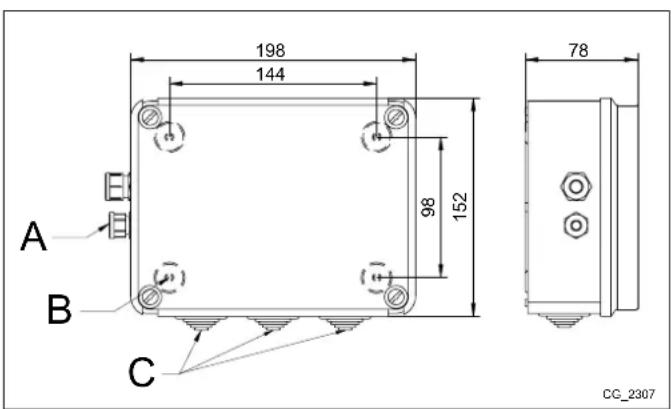
2.2 WALL INSTALLATION
Mount the device on the wall with the two pressure screws supplied with the accessory, using the holes in the junction box. Connect the unit to the master boiler and the accessories as described in section 3. To secure it, see the measurements indicated in the figure to the side.
| A C | amp for power cable |
| B Holes for wall-mounting | |
| C | Grommets for external electrical accessories |

Only power the unit after completing installation.
3. ELECTRICAL CONNECTIONS

Pass the cables connecting the boiler to the accessories using the relative grommets holes on the bottom of the boiler.
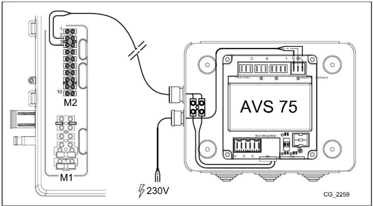
3.1 BOILER ELECTRICAL CONNECTIONS
- Connect the device to a 230V single-phase power supply with earth.
- This appliance must only be installed by a qualified installer.
- Before switching on, make sure all the electrical connections have been made correctly.
- Carefully read the boiler instructions manual.
- Connect the 2-pin terminal block of the AVS75 unit to the boiler terminal block M2 (2-3) using a "HAR H05 VV-F" 2 × 0.5 ~mm harmonicised cable with a maximum length of 150 ~m .
3.2 ELECTRICAL CONNECTIONS OF EXTERNAL ACCESSORIES
To connect the AVS75 accessory to the external accessories proceed as follows (use "HAR H05 VV-F" harmonised cables with a cross-section of 1mm^2 ):
MIXED CIRCUIT CASE (see diagram chap. 3.2.1)
- Connect the mixed zone pump to the QX23 connector on the AVS75.
- Connect the mixed zone delivery sensor to the BX21 connector on the AVS75 (QAD36 supplied).
- Connect the mixing valve to the QX22-QX21 connector
- Connect the ambient thermostat to the H2 connector on the AVS75.
- Connect the safety thermostat to the FX23 connector.
DHW SOLAR PLANT CASE (see diagram chap. 3.2.2)
- Connect the solar plant pump to the QX23 connector on the AVS75.
- Connect the solar boiler sensor to the BX22 connector on the AVS75.
- Connect the solar panel sensor to the BX21 connector on the AVS75.
| KEY TO CONNECTORS | |
| N⊕L (L-N) | AVS 75 power input |
| X50 | Connector linking the SIEMENS electronic board to the AVS 75 accessory. |
| X30 | Connector for linking another accessory via a flat cable. |
| T (QX21⊕N) | 230V programmable relay output |
| T (QX22⊕N) | 230V programmable relay output |
| S (QX23⊕N) | 230V programmable relay output |
| C (EX21-FX23-L) | connection to safety thermostat (only for mixed zones) |
| n (H2-M) | 12VDC digital or 0-10VDC analogue programmable input. |
| n (BX21-M) | NTC 10K / Pt1000 sensor programmable input |
| n (BX22-M) | NTC 10K / Pt1000 sensor programmable input |

3.2.1 MIXED CIRCUIT CASE
| A FLOW PROBE QAD36 C MIXED ZONE PUMP | ||
| B MIXING VALVE D SAFETY THERMOSTAT |
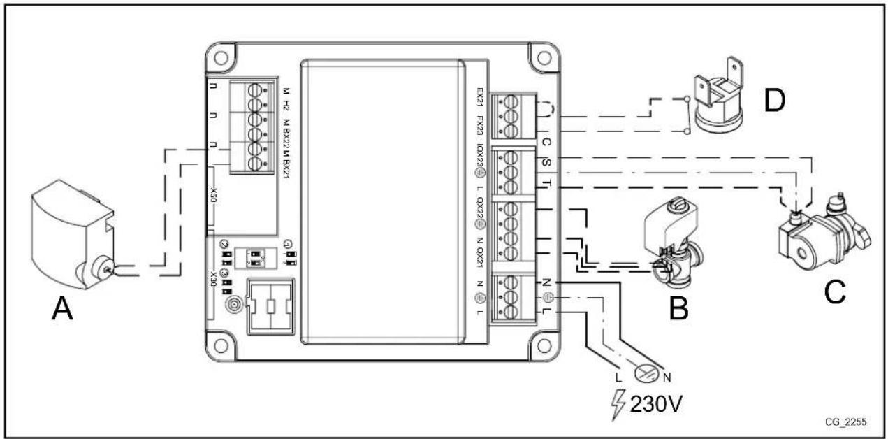
For a mixed zone, connect the safety thermostat between terminals FX23 - L and jumper terminals EX21 - FX23. The circuit pump connected to relay QX23 is thus internally connected in series to the safety thermostat.
If the relay output QX23 must be used for functions other than those required for the mixed zone, jumper terminals FX23 - L.
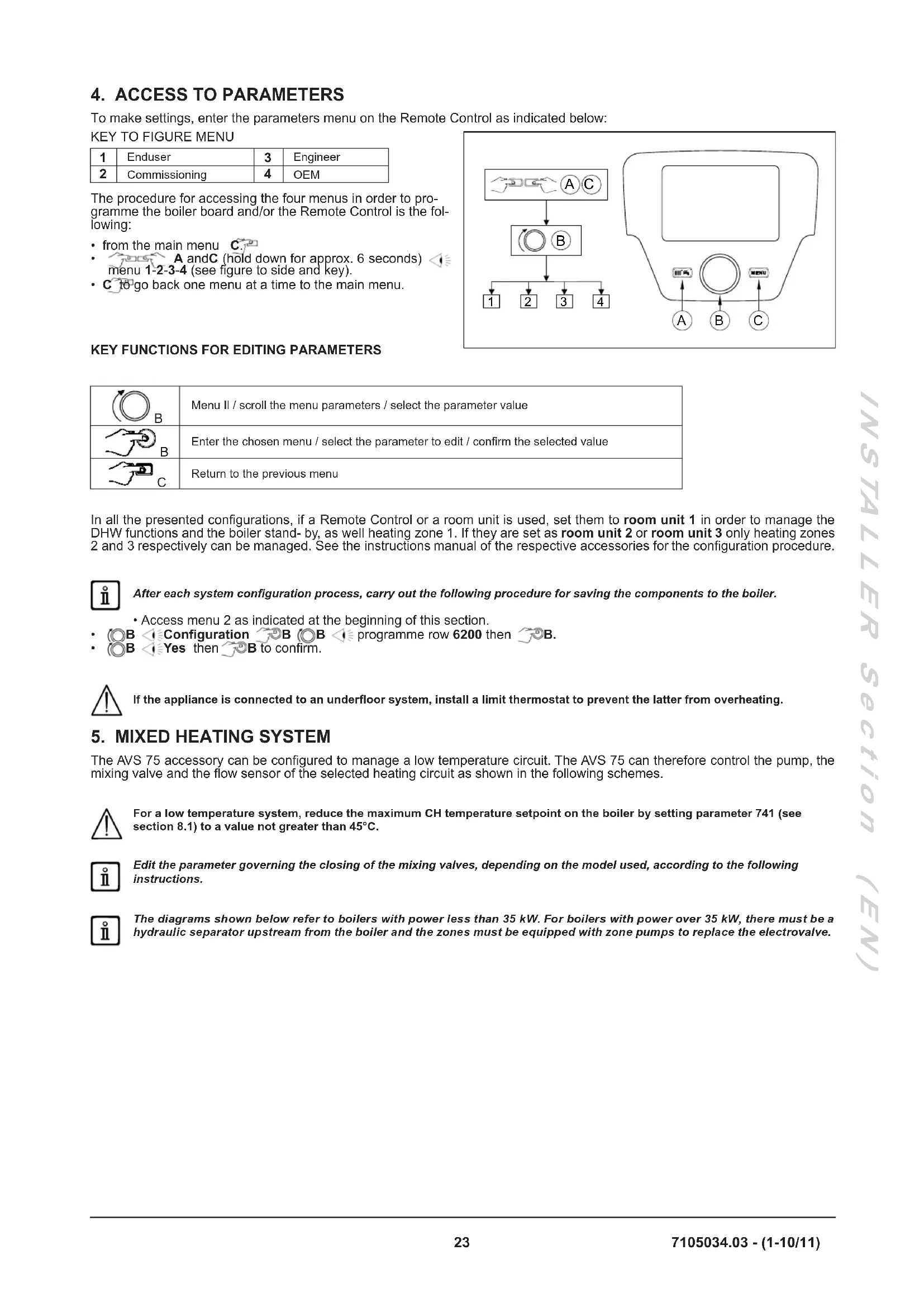
To make settings, enter the parameters menu on the Remote Control as indicated below:
KEY TO FIGURE MENU
| 1 | Enduser | 3 | Engineer |
| 2 | Commissioning | 4 | OEM |
The procedure for accessing the four menus in order to programme the boiler board and/or the Remote Control is the following:
from the main menu C.
A and C (hold down for approx. 6 seconds)
menu 1-2-3-4 (see figure to side and key).
- C to go back one menu at a time to the main menu.
KEY FUNCTIONS FOR EDITING PARAMETERS
| B | Menu II / scroll the menu parameters / select the parameter value |
| B | Enter the chosen menu / select the parameter to edit / confirm the selected value |
| C | Return to the previous menu |
In all the presented configurations, if a Remote Control or a room unit is used, set them to room unit 1 in order to manage the DHW functions and the boiler stand- by, as well heating zone 1. If they are set as room unit 2 or room unit 3 only heating zones 2 and 3 respectively can be managed. See the instructions manual of the respective accessories for the configuration procedure.

After each system configuration process, carry out the following procedure for saving the components to the boiler.
-
Access menu 2 as indicated at the beginning of this section.
-
B Configuration B programme row 6200 then B.
B Yes then B to confirm.

If the appliance is connected to an underfloor system, install a limit thermostat to prevent the latter from overheating.
The AVS 75 accessory can be configured to manage a low temperature circuit. The AVS 75 can therefore control the pump, the mixing valve and the flow sensor of the selected heating circuit as shown in the following schemes.

For a low temperature system, reduce the maximum CH temperature setpoint on the boiler by setting parameter 741 (see section 8.1) to a value not greater than 45^ .

Edit the parameter governing the closing of the mixing valves, depending on the model used, according to the following instructions.

The diagrams shown below refer to boilers with power less than 35kW . For boilers with power over 35kW , there must be a hydraulic separator upstream from the boiler and the zones must be equipped with zone pumps to replace the electrovalve.
5.1 SCHEME 1
Low temperature zone with ambient unit - heating circuit (1) High temperature zone with ambient thermostat - heating circuit (2)
| 1 External sensor - terminal block M2 (4-5) on boiler |
| 2 Low temperature zone mixing valve (QX21-N-QX22) |
| 3 Low temperature circuit pump (QX23-N) |
| 4 Low temperature circuit probe (BX21-M) |
| 5 Low temperature circuit safety thermostat (FX23-L) |
| 6 Ambient unit - terminal block M2 (1-2-3) on boiler |
| 7 Electrovalve or externally powered high temperature zone pump |
| 8 High temperature zone ambient thermostat (for connection see chapter 7.1) |
Enter menu 2 from the control panel, as described in section 4, and make the following settings:
| MENU | PROGRAMME ROW | VALUE TO SET DESCRIPTION | |
| CONFIGURATION | 5715 On Heating circuit 2 enable | ||
| 5977 | Room thermostat CH2 | Enable thermostat for circuit 2 (contact 1-2 terminal block M1) | |
| 6020 Tems / mode CH1 Low temperature zone enable | |||
| 6024 | Limit thermostat CH | EX21 input enabled as low temperature zone protection | |
| 6046 | Heat generation lock | H2 input enabled as low temperature zone protection | |
| HEATING CIRCUIT 1 | 742 | --- | Modulating flow temperature enable (low temperature zone) |
| 834 | Default 180 s | Mixing valve close time | |
The room unit can directly control the low temperature zone according to the required room temperature. If, when turning the knob B on the main menu, the display visualises the boiler flow temperature instead of the ambient temperature, parameter 742 has not been set correctly.
5.2 SCHEME 2
More than one low temperature zone with ambient thermostat and shared room unit - heating circuit(1) High temperature zone with ambient thermostat - heating circuit (2)
| 1 External sensor - terminal block M2 (4-5) of boiler |
| 2 Low temperature zone mixing valve (QX21-N-QX22) |
| 3 Low temperature circuit pump (QX23-N) |
| 4 Low temperature circuit probe (BX21-M) |
| 5 Low temperature circuit safety thermostat (FX23-L) |
| 6 Room unit - terminal block M2 (1-2-3) of boiler |
| 7 Low temperature zone ambient thermostat input (H2-M - for connection see chapter 7.4) |
| 8 Electrovalve or externally powered high temperature zone pump |
| 9 High temperature zone ambient thermostat (for connection see chapter 7.1) |
Enter menu 2 from the control panel, as described in section 4, and make the following settings:
| MENU | PROGRAMME ROW | VALUE TO SET DESCRIPTION | |
| CONFIGURATION | 5715 On Heating circuit 2 enable | ||
| 5977 | Room thermostat CH2 | Enable thermostat for circuit 2 (contact 1-2 terminal block M1) | |
| 6020 Tems / mode CH1 Low temperature zone enable | |||
| 6024 | Limit thermostat CH | EX21 input enabled as low temperature zone protection | |
| 6046 | Room thermostat CH1 | H2 input enabled as low temperature zone room thermostat | |
| HEATING CIRCUIT 1 | 710 | 35°C | Room setpoint (low temperature zone) |
| 834 | Default 180 s | Mixing valve close time | |
Set the comfort temperature to it maximum value (35^) to ensure the low temperature zones work correctly. This ensures that the room unit does not block the heat demand of the individual room thermostats managing the subzones.
In this case, the room unit manages the low temperature system, but it cannot be used to manage the temperature of one of the rooms. Turn knob B to display the boiler flow temperature. The heating circuit operates with a fixed flow.
5.3 SCHEME 3
Low - heating circuit (1) and high temperature - heating circuit (2) zones with ambient thermostat.
| 1 External sensor - terminal block M2 (4-5) of boiler |
| 2 Low temperature zone mixing valve (QX21-N-QX22) |
| 3 Low temperature circuit pump (QX23-N) |
| 4 Low temperature circuit probe (BX21-M) |
| 5 Low temperature circuit safety thermostat (FX23-L) |
| 6 Low temperature zone room thermostat input (H2-M) |
| 7 Electrovalve or externally powered high temperature zone pump |
| 8 High temperature zone ambient thermostat (for connection see chapter 7.1) |
Enter menu 2 from the control panel, as described in section 4, and make the following settings:
| MENU | PROGRAMME ROW | VALUE TO SET DESCRIPTION | |
| CONFIGURATION | 5715 On Heating circuit 2 enable | ||
| 5977 | Room thermostat CH2 | Enable thermostat for circuit 2 (contact 1-2 terminal block M1) | |
| 6020 Tems / mode CH1 Low temperature zone enable | |||
| 6024 | Limit thermostat CH | EX21 input enabled as low temperature zone protection | |
| 6046 | Room thermostat CH1 | H2 input enabled as low temperature zone room thermostat | |
| HEATING CIRCUIT 1 | 834 | Default 180 s | Mixing valve close time |
6. ZONE HEATING SYSTEM
If it is not necessary to manage mixed systems, the AVS75 accessory can be used to command zone pumps/electrovalves, as illustrated below:

To avoid frequent starting and stopping, raise the minimum temperature setpoint of the boiler in the heating mode by setting parameters 740, 1040 and 1340 (see section 8.1) to not less than 45^ .
6.1 SCHEME 4
Two zones with ambient unit heating circuits (1 and 2) and 1 zone with room thermostat heating circuit (3).
| 1 | External sensor - terminal block M2 (4-5) of boiler | 5 | Circuit 2 ambient unit - terminal block M2 (1-2-3) of boiler |
| 2 | Circuit 1 zone pump or electrovalve (QX21-N)* | 6 | Electrovalve or externally powered circuit 3 zone pump |
| 3 | Circuit 1 ambient unit - terminal block M2 (1-2-3) of boiler | 7 | Circuit 3 ambient thermostat (for connection see chapter 7.1) |
| 4 | Electrovalve or circuit 2 zone pump (QX22-N)* |
* The AVS 75 accessory cannot directly command a 3-wire electrovalve. A relay with an exchange contact must be used instead.

Room units 3 and 5 are connected in parallel.
The ambient units can directly control their respective zones according to the desired room temperature. Enter menu 2 from the control panel, as described in section 4, and make the following settings:
| MENU | PROGRAMME ROW | VALUE TO SET | DESCRIPTION |
| CONFIGURATION | 5715 | On | Heating circuit 2 enable |
| 5721 | On | Heating circuit 3 enable | |
| 5977 | Room thermostat CH3 | Enable thermostat for circuit 3 (contact 1-2 terminal block M1) | |
| 6020 | Multifunctional | - | |
| 6030 | Heating pump CH1 Q2 | Circuit 1 pump/electrovalve control | |
| 6031 | Heating pump CH2 Q6 | Circuit 2 pump/electrovalve control | |
| HEATING CIRCUIT 1 | 742 | --- | Enable modulating flow temperature (heating circuit 1) |
| HEATING CIRCUIT 2 | 1042 | --- | Enable modulating flow temperature (heating circuit 2) |
The room units can directly control their respective zones according to the desired room temperature. If, when turning the knob B on the main menu, the display visualises the boiler flow temperature instead of the ambient temperature, parameters 742, 1042 and 1034 have not been set correctly.
6.2 SCHEME 5
| 1 | External sensor - terminal block M2 (4-5) of boiler | 5 | Circuit 2 ambient unit - terminal block M2 (1-2-3) of boiler |
| 2 | circuit 1 zone electrovalve (QX21-N)* | 6 | circuit 3 zone electrovalve (QX21-N)* |
| 3 | Circuit 1 ambient unit - terminal block M2 (1-2-3) of boiler | 7 | Circuit 3 ambient unit - terminal block M2 (1-2-3) of boiler |
| 4 | circuit 2 zone electrovalve (QX22-N)* |
- The AVS 75 accessory cannot directly command a 3-wire electrovalve. A relay with an exchange contact must be used instead.

Room units 3 - 5 and 7 are connected in parallel.
The room units can directly control their respective zones according to the desired room temperature. Enter menu 2 from the Remote Control, as described in section 4, and make the following settings:
| MENU | PROGRAMME ROW | PARAMETER VALUE TO SET DESCRIPTION | ||
| CONFIGURATION | 5715 | Temps / mode CH2 | On | Heating circuit 2 enable |
| 5721 | Temps / mode CH3 | On | Heating circuit 3 enable | |
| 5977 | Function input H5 | None | Disable thermostat in terminal block M1 (1-2) on board | |
| 6020 | Function extension module 1 | Multifunctional | - | |
| 6030 | Relay output QX21 module 1 | Heating pump CH1 Q2 | Circuit 1 pump/electrovalve control | |
| 6031 | Relay output QX22 module 1 | Heating pump CH2 Q6 | Circuit 2 pump/electrovalve control | |
| 6032 | Relay output QX23 module 1 | Heating pump CH3 Q20 | Circuit 3 pump/electrovalve control | |
| HEATING CIRCUIT 1 | 742 | Flow temp setpoint room stat --- | Enable modulating flow temperature (heating circuit 1) | |
| HEATING CIRCUIT 2 | 1042 | Flow temp setpoint room stat | --- | Enable modulating flow temperature (heating circuit 2) |
| HEATING CIRCUIT 3 | 1342 | Flow temp setpoint room stat | --- | Enable modulating flow temperature (heating circuit 3) |
The room units can directly control their respective zones according to the desired room temperature. If, when turning the knob B on the main menu, the display visualises the boiler flow temperature instead of the ambient temperature, parameters 742, 1042 or 1342 have not been set correctly.
7. ELECTRICALLY CONNECTING THE AMBIENT THERMOSTAT

The operating temperature is the same for all circuits.

The relays can be replaced with valves equipped with micro limit switches and vice versa.
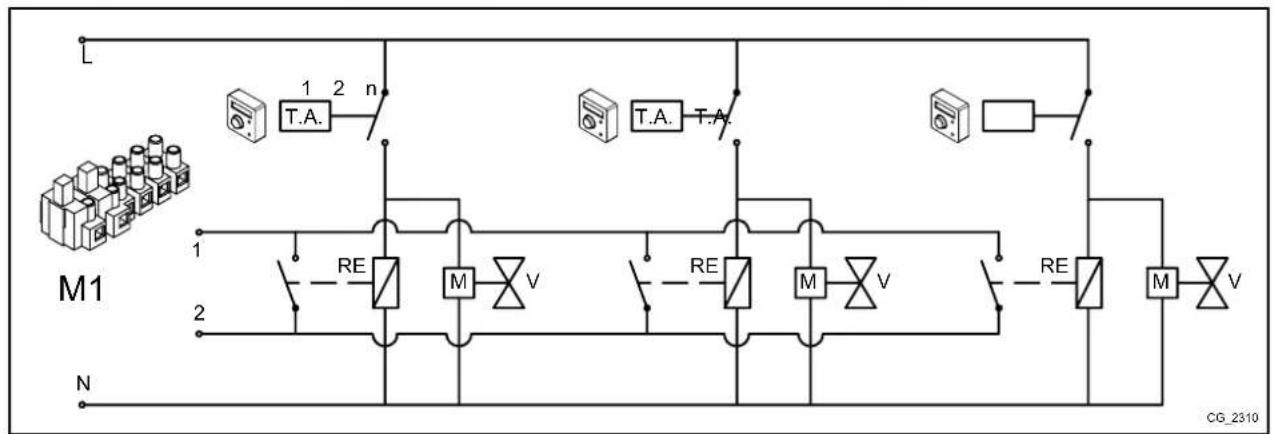
7.1 CASE - 1 - Connecting a single ambient thermostat in a high temperature zone.
Connect the ambient thermostat to the external electric network (230V) which will supply the zone valve (or pump) and the relay coil; connect the relay contact to the boiler M1 terminal block (1-2).
7.2 CASE - 2 - Connecting ambient thermostats for a high temperature multi-zone system.
Connect the ambient thermostat in parallel to the external electric network (230V) which will supply the zone valve (or pump) and the relay coils; connect the relay contacts in parallel to the boiler M1 terminal block (1-2).
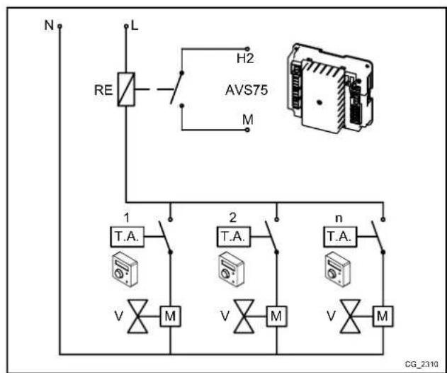
7.3 CASE - 3 - Connecting ambient thermostats for a low temperature multi-zone system.
Connect the ambient thermostats in parallel to the external electric network (230V) which will supply the zone valves (or pumps) and the relay coil; connect the relay contact to the AVS75 H2-M terminal blocks.
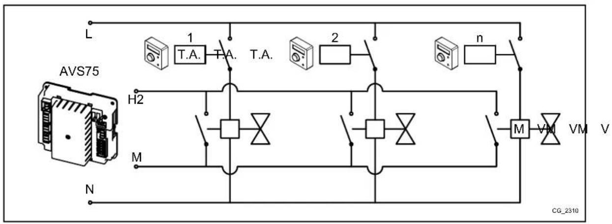
7.4 CASE - 4 - Connecting ambient thermostats for a low temperature multi-zone system with micro limit switches in the zone valves.
Connect the ambient thermostats in parallel to the external electric network (230V) which will supply the zone valves; connect the micro switch contacts in parallel to the AV75 H2-M terminal blocks.
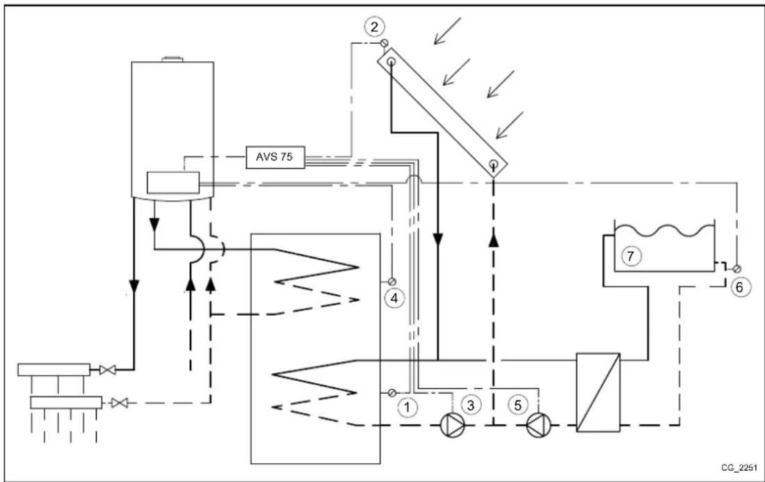
8. DHW SOLAR PLANT
In this configuration, the AVS 75 accessory can manage the solar circuit pump, the manifold sensor and the storage boiler sensor (relative to the solar plant) according to the following scheme:
| 1 | solar storage heater sensor B31 (BX22-M) | 3 | solar circuit pump Q5 (QX23-N) |
| 2 | solar storage heater manifold B6 (BX21-M) | 4 | storage boiler sensor B3 - terminal block M2 (9-10) on board |
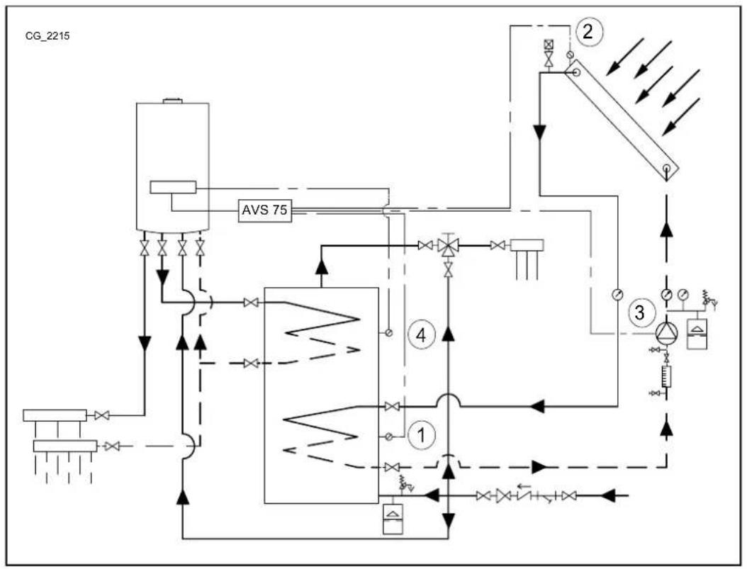

Use specific sensors for this application (supplied as an accessory).
Enter menu 2 from the Remote Control, as described in section 4, and make the following settings:
| MENU | PROGRAMME ROW | VALUE TO SET | DESCRIPTION |
| CONFIGURATION | 6020 | Solar HW | Solar function enable |
The following parameters can be used. If solar panels with vacuum tubes are used, enable the specific safety function (parameters 3830, 3831):
| MENU | PROGRAMME ROW | VALUE TO SET | DESCRIPTION |
| CONFIGURATION | 3810 Default 8°C | Temperature difference between manifold and solar sensor storage boiler for solar pump activation | |
| 3811 Default 4°C | Temperature difference between manifold and solar sensor storage boiler for solar pump deactivation | ||
| 3850 Default “---” | Temperature above which the manifold pump circulates (only if the maximum temperature of the storage boiler is not reached) | ||
| Access menu 3 section 5.2) | |||
| SOLAR | 3830 Default “---” | Maximum stop time of solar pump if the manifold temperature reaches its maximum value (parameter 3850) within the minimum circulation time (parameter 3831) | |
| 3831 Default 30s Minimum | circulation time of manifold pump | ||

When the symbol appears on the display, it means that the solar plant pump is heating the storage boiler.
9. PARAMETERS SETTING
9.1 HEATING SYSTEM
| Remote Control | CR 1, 2, 3 HEATING CIRCUIT MENU | Factory setting | Minimum | Maximum | |||
| CR1 | CR2 | CR3 | |||||
| 700 | 1000 | 1300 | Off: the boiler lights when the room temperature is < 6°C Timed: the room temperature depends on the set time band Reduced: the room temperature is reduced On: the room temperature is comfort | - | Comfort | - | - |
| 710 | 1010 | 1310 | Comfort room temperature | °C | 20 | Reduced | Maximum comfort |
| 712 | 1012 | 1312 | Reduced room temperature | °C | 16 | Anti-freeze | Comfort |
| 714 | 1014 | 1314 | Anti-freeze room temperature | °C | 6 | 4 | Reduced |
| 720 | 1020 | 1320 | Climate curve selection for external sensor | - | 1.5 | 0.1 | 4 |
| 730 | 1030 | 1330 | With an external sensor and in the automatic operating mode, automatic heating control activates (ON-OFF) depending on the set temperature (external) | °C | --- | 8 | 30 |
| 740 | 1040 | 1340 | Minimum flow value (e.g.: with the modulating flow function enabled) | °C | 25 | 8 | Maximum setpoint |
| 741 | 1041 | 1341 | Maximum flow value (e.g.: with the modulating flow function enabled) | °C | 80 | Minimum setpoint | 95 |
| 742 | 1042 | 1342 | Flow temperature with room unit (- = modulating flow enable) | °C | 80 | Minimum setpoint | Maximum setpoint |
| 750 | 1050 | 1350 | Importance of room temperature with respect to the external temperature and vice-versa (room influence function): - %: pure climate 1.99 %: climate with room offset 100 %: pure room | % 50 | 1 | 100 | |
| 760 | 1060 | 1360 | Boiler off differential depending on the required room temperature | °C | 0.5 | 0.5 | 4 |
| 809 | 1109 | 1409 | The boiler pump and the circuit pump remain active 24h | - | no | - | - |
| 834 | 1134 | 1434 | Closing time of low temperature mixing valve | s | 180 | 30 | 873 |
| 850 | 1150 | 1450 | The 'manual' function is recommended | - | off | ||
| 851 | 1151 | 1451 | Flow temperature for dry screed function | °C | 25 | 0 | 95 |
| 855 | 1155 | 1455 | Current flow temperature of dry screed function | °C | - | - | - |
| 856 | 1156 | 1456 | Day of the week during activation of dry screed function | - | - | - | - |
CR = Heating Circuit
9.2 DHW SYSTEM
| Remote Control | DHW CIRCUIT MENU | Factory setting | Minimum | Maximum | |
| 1600 | Operating mode Off = setpoint equal to anti-freeze setpoint On = rated setpoint Eco = pre-heating disabled | - | on -- | ||
| 1610 DHW rated setpoint °C 60 35 60 | |||||
| 1612 Reduced DHW setpoint °C 35 8 60 | |||||
| 1620 | Hourly programming enable | - | 24h/day | - | - |
| 1640 | Anti-legionellosis function operating mode: Off Periodically Fixed weekday | - | off -- | ||
| 1641 | N° days between one anti-legionellosis function and the next (1...7) | - | 7 | - | - |
| 1642 | Anti-legionellosis function day (Monday...Sunday) | - | Monday | - | - |
| 1644 | Anti-legionellosis start time | - | ---- | - | - |
| 1660 DHW recirculation pump operating mode | - | Hot water release | - | - | |
| 1663 | Temperature at which the DHW pump stops | °C | 45 | 8 | 60 |
9.3 SUNDRY PARAMETERS
| Control panel | CONFIGURATION MENU | Factory setting |
| 5710 | Heating circuit 1 enable | on |
| 5721 | Heating circuit 3 enable | off |
| 5730 | Setting of DHW sensor depending on the type of boiler(stORAGE or instantaneous) | |
| 5731 | Type of actuator for DHW priority control | Diverting valve |
| 5970 | DHW priority sensor (for instantaneous boilers) | - |
| 5971 | Home position of contact | - |
| 5973 | Parameters for determining DHW demand water flow | - |
| 5974 | - | |
| 5975 | - | |
| 5976 | - | |
| 5977 | Input for ambient thermostat of one of the heating circuits | Room thermostat CH1 |
| 5978 | - | |
| 6020 | Multifunction: the inputs and outputs can be configured manually | - |
| 6021 | Heating circuit 1, 2 or 3: manages a mixed zone (1, 2 or 3 - chapter 5)Return temp controller: not used | - |
| 6022 | Solar HW: manages a solar plant with 2 sensors and pump (section 7)Primary contr/system pump: not used | - |
| 6024 | Input for low temperature circuit safety thermostat (module 1) | - |
| 6026 | Input for low temperature circuit safety thermostat (module 2) | - |
| 6028 | Input for low temperature circuit safety thermostat (module 3) | - |
| 6030...6038 | See section 9 | - |
| 6040...6045 | See section 9 | - |
| 6046...6068 | See section 9 | - |
| 6097 | Type of sensor used for solar manifold | Pt 1000 |
| 6200 | Saving of all the sensors connected in the boiler and accessories (section 4) | - |
| 6212 | Manufacturer information | - |
| 6213 | Manufacturer information | - |
| 6215 | Manufacturer information | - |
| 6217 | Manufacturer information | - |
| 6230 | Manufacturer information | - |
| 6231 | Manufacturer information | - |
| 6704 | Internal code display enable | yes |
| 6705 | Internal code of current error | - |
| 6706 | Burner phase during which the error appeared | - |
| 6710 | External alarm reset (section 9) | no |
| 6800 | Last error | - |
| 6805 | Internal code of last error | - |
| 6806 | Burner phase of last error | - |
| 6810 to 6996 Error log | - | |
10. SUNDRY FUNCTIONS
As well as the above settings, the inputs and outputs can also be configured according to system requirements. The following examples consider the relay QX21 and sensor BX21 output of the accessory, though the same applies to relays QX22, QX23 and the sensor BX22. In all cases, set the accessory to "Multifunctional".
| MENU | PROGRAMME ROW | PARAMETER VALUE TO | SET DESCRIPTION | |
| CONFIGURATION | 6020 | Extension module 1 function | Multifunctional Solar function enable | |
If a storage boiler is used in the DHW circuit, the circulation pump can be controlled. This function is limited by the hourly programming of the DHW system. To minimise circulation losses, the function activates the pump for 10 minutes followed by a 20 minute pause. Enter menu 2 from the control panel, as described in section 4:
| MENU | PROGRAMME ROW | VALUE TO SET DESCRIPTION | |
| CONFIGURATION | 6030 | Circulating pump Q4 | DHW recirculation pump enable (relay QX21 output) |
| 6040 HW | circulation sensor B39 DHW | recirculation sensor enable (sensor BX21) | |
| DHW CIRCUIT | 1663 | factory setting = 45°C | DHW temperature below which the pump is enabled (recirculation setpoint) |
10.2 SOLAR PLANT FOR SWIMMING POOL
Heating a swimming pool with solar panels can be achieved as follows.
| 1 | Solar storage heater sensor B31 (BX22-M) | 5 | Swimming pool pump (QX21-N) |
| 2 | Solar storage heater manifold B6 (BX21-M) | 6 | Swimming pool heating return sensor – terminal block M2 in boiler |
| 3 | Solar circuit pump Q5 (QX23-N) | 7 | Swimming pool |
| 4 | Storage boiler sensor B3 – terminal block M2 (9-10) of boiler |

Use specific sensors for this application (supplied as an accessory).
Configure the system as described in section 8. At this point the DHW system is configured to use solar panels. Enter menu 2 from the Remote Control, as described in section 4:
| MENU | PROGRAMME ROW | VALUE TO SET | DESCRIPTION |
| CONFIGURATION | 5931 | Swimming pool sensor B13 | Swimming pool sensor enable (BX2 sensor input) |
| 6030 | Solar ctrl elem swi pool K18 | Swimming pool heating pump enable (relay QX21 output) | |
| DHW CIRCUIT | 6046 | Release swi pool solar | Swimming pool heating activation (e.g.: via float or manual command) |
It is important to use contact H2 as it assures correct system operation, allowing heat exchange with the swimming pool only if the latter allows it to do so. Make sure the swimming pool is full of water and operative.
10.3 GENERIC HEAT DEMAND
A generic heat demand does not come from one of the three available heating circuits and/or from the DHW circuit. This type of demand is called user demand and is used to provide heat to external units such as heating water in a swimming pool.
To enable this function, perform the following configuration procedure. Enter menu 2 from the Remote Control, as described in section 4:
| MENU | PROGRAMME ROW | VALUE DESCRIPTION | |
| CONFIGURATION | 6030 | Cons circuit pump VK1 Q15 | External demand 1 pump enable (relay QX21 output) |
| 6046 | Consumer request VK1 External demand 1 contact | ||
| USER CR1 | 1859 factory setting = 70°C Heating flow temperature for external demand 1 | ||
If the user demand is provided via a 0-10 V analogue signal, set parameter 6046 to "User demand CR1 10V". Also set signal characteristics using the following parameters:
| 6049 | Valore tens. 1 H2 modulo 1 | 6050 | Valore 1 H2 modulo 1 | 6051 | Valore tens. 2 H2 modulo 1 | 6052 | Valore 2 H2 modulo 1 |
10.4 OTHER CONFIGURATIONS
Further configurations are summarised below:
QX21 relay
| Alarm output K10 | Alarm (e.g.: condominium) |
| System pump Q14 | Pump active at every heating or external demand |
| Time setting 5 K13 | Contact commanded from “aux hourly programme” |
| Refrigeration request K28 Cooling | Demand from chiller circuit 1 |
| Water refill K34 | Boiler automatic filling valve |
| Fan shutdown K38 | External fan control |
BX21 sensor
| Buffer sensor B4 | Storage boiler sensor for heating (higher) |
| Buffer sensor B41 | Storage boiler for heating (lower) |
| Buffer sensor B42 | Third storage boiler probe for heating (half of storage boiler) |
H2 input
| Error/alarm message | External alarm signal |
| Boiler flow switch | Boiler flow switch command (only to use if not on the boiler) |
| Boiler temp limiter | Boiler thermostat command (only to use if not on the boiler) |
| Consumer request VK1 10V | External demand 1 with 0-10V signal (*) |
| Pressure measurement 10V | Pressure measurement with 0-10V signal (*) |
| Preselected output 10V | Boiler power adjustment according to 0-10V signal (*) |
- To use the functions set the characteristics of the analogue signal using the following parameters present in the Configuration menu of the Remote Control:
| 6049 | Voltage value 1 H2 module 1 | 6050 | Funct value 1 H2 module 1 | 6051 | Voltage value 2 H2 module 1 | 6052 | Funct value 2 H2 module 1 |

The illustrated configurations also apply to the other board relays/sensors/Input, such as relay QX1 (row 5890) or sensors BX2 (row 5931) and BX3 (row 5932).
11. LIST OF FAULTS
| E | Fault Description of fault | |
| 10 | External probe sensor | Heating circuit enabled with no command (thermostat, room unit or external unit) or external probe faulty |
| 84 B$B, address conflict 2 or more | room units configured for the same heating circuit | |
| 98 Additional module 1 AVS 75 accessory not detected or recognised | ||
| 99 Additional module 2 AVS 75 accessory not detected or recognised | ||
| 373 Additional module 3 AVS 75 accessory not detected or recognised | ||
| 30 Flow sensor 1 Mixed circuit 1 sensor not detected | ||
| 32 Flow sensor 2 Mixed circuit 2 sensor not detected | ||
| 260 Flow sensor 3 Mixed circuit 3 sensor not detected | ||
| 335 BX21 no function BX21 sensor not configured | ||
| 336 BX22 no function BX22 sensor not configured | ||
| 324 BX same sensors | Two or more sensors configured for the same function | |
| 52 DHW 2 sensor DHW solar sensor | not detected | |
| 73 Manifold 1 probe Solar manifold sensor not detected | ||
| 57 DHW circulation sensor DHW circulation sensor not detected | ||
| 243 Swimming pool sensor Swimming pool sensor not detected | ||
| 25 Wood boiler sensor Biomass boiler sensor not detected | ||
| 346 No Q10 boiler pump Biomass boiler pump not detected | ||
12. TECHNICAL SPECIFICATIONS
| Power input | Input voltage | AC 230 V (±10 %) | |||||
| Operating frequency | 50/60 Hz | ||||||
| Power input | 4 VA | ||||||
| Power supply fuse (power supply and outputs) | max. 10 AT | ||||||
| Cables | Rigid or flexible wire (braided or with ferrule) | - | |||||
| one-pole | 0.5...2.5 mm² | ||||||
| two-pole | 0.5...1.5 mm² | ||||||
| Operating data | Software class | A | |||||
| Operating mode EN 60 730 | 1b (automatic operation) | ||||||
| Inputs | Digital input H2 | - | |||||
| very low safety voltage for clean contact | - | ||||||
| low voltage contact | - | ||||||
| voltage with contact open | DC 12 V | ||||||
| current with contact closed | DC 3 mA | ||||||
| Analogue input H2 | - | ||||||
| Very low protection voltage | - | ||||||
| range | DC 0..10 V | ||||||
| internal resistance | > 100 kW | ||||||
| Input L | AC 230 V (±10%) | ||||||
| internal resistance | > 100 kW | ||||||
| Input sensors BX21, BX22 | NTC 10k | ||||||
| permitted connection cables (copper) | - | ||||||
| cross-section | mm² | 0.25 | 0.5 | 0.75 | 1.0 | 1.5 | |
| maximum length | m | 20 | 40 | 60 | 80 | 120 | |
| Outputs | Output relay | - | |||||
| current range | AC 0.02...2 (2) A | ||||||
| maximum starting current | 15 A for ≤1 s | ||||||
| maximum current (for all relays) | AC 6 A | ||||||
| voltage range | AC 24...230 V (for clean contact) | ||||||
| Interface | BSB | connection with 2 cables, not interchangeable | |||||
| length of base unit - peripherals | max. 200 m | ||||||
| total length | max. 400 m (maximum capacity of cable 60nF) | ||||||
| cable cross-section | 0.5 mm² | ||||||
SOMMAIRE
2.1 CONDITIONS REQUISES POUR L'INSTALLATION AU MUR
10.3 VŠEOBECNÍ POŽADAVEK TEPLA
- PERICOLO ALTA TENSIONE
- DESCRIPTION OF SYMBOLS
- WARNING
- DANGER-HIGH VOLTAGE
- IMPORTANT INFORMATION
- INTRODUCTION
- 2.DESCRIPTION OF ACCESSORY
- WALL INSTALLATION REQUIREMENTS
- WALL INSTALLATION
- ELECTRICAL CONNECTIONS
- BOILER ELECTRICAL CONNECTIONS
- ELECTRICAL CONNECTIONS OF EXTERNAL ACCESSORIES
- MIXED CIRCUIT CASE
- KEY FUNCTIONS FOR EDITING PARAMETERS
- SCHEME 1
- SCHEME 2
- SCHEME 3
- ZONE HEATING SYSTEM
- SCHEME 4
- SCHEME 5
- ELECTRICALLY CONNECTING THE AMBIENT THERMOSTAT
- CASE - 1 - Connecting a single ambient thermostat in a high temperature zone.
- CASE - 2 - Connecting ambient thermostats for a high temperature multi-zone system.
- CASE - 3 - Connecting ambient thermostats for a low temperature multi-zone system.
- CASE - 4 - Connecting ambient thermostats for a low temperature multi-zone system with micro limit switches in the zone valves.
- DHW SOLAR PLANT
- PARAMETERS SETTING
- HEATING SYSTEM
- SUNDRY FUNCTIONS
- SOLAR PLANT FOR SWIMMING POOL
- GENERIC HEAT DEMAND
- OTHER CONFIGURATIONS
- LIST OF FAULTS
- TECHNICAL SPECIFICATIONS
- SOMMAIRE
- CONDITIONS REQUISES POUR L'INSTALLATION AU MUR
- VŠEOBECNÍ POŽADAVEK TEPLA
Brand : Baxi
Model : 90 F
Category : Boiler