Platinum BC iPlus V200 R32 - Heat pump Baxi - Free user manual and instructions
Find the device manual for free Platinum BC iPlus V200 R32 Baxi in PDF.
| Product type | Heat pump |
| Brand | Baxi |
| Model | Platinum BC iPlus V200 R32 |
| Refrigerant | R32 |
| Power supply | Single-phase 230 V / 50 Hz |
| Number of heating circuits | Up to 2 circuits (direct and mixed) |
| Domestic hot water production | With domestic hot water tank (optional) |
| Regulation type | Electronic, with outdoor sensor and climate regulation |
| Reversing valve | Integrated for reversible operation (heating/cooling) |
| Maximum heating flow temperature | Up to 60 °C (varies by configuration) |
| Frost protection | Integrated, with safety thermostats |
| Safety valve | Set to 7 bar on the sanitary circuit |
| Mandatory hydraulic filter | 400 µm on heating circuit |
| Routine maintenance | Filter cleaning, annual check by a professional |
| Spare parts | Reversing valve, motor, sensor, connectors (references provided) |
| Indoor unit weight | Approximately 45 kg (estimate) |
| Indoor unit dimensions | Approximately 600 x 800 x 400 mm (estimate) |
| Number of manual pages | 84 pages |
| Available languages | FR, DE, EN, ES, IT, NL, PL, PT |
Frequently Asked Questions - Platinum BC iPlus V200 R32 Baxi
User questions about Platinum BC iPlus V200 R32 Baxi
0 question about this device. Answer the ones you know or ask your own.
Ask a new question about this device
Download the instructions for your Heat pump in PDF format for free! Find your manual Platinum BC iPlus V200 R32 - Baxi and take your electronic device back in hand. On this page are published all the documents necessary for the use of your device. Platinum BC iPlus V200 R32 by Baxi.
USER MANUAL Platinum BC iPlus V200 R32 Baxi
1 Reversal valve and domestic hot water sensor 23
1.1Assembling the reversal valve 23
1.2 Hydraulic connection diagram 24
1.3 Identifying the PCB used 24
1.4 Indoor module with PCB - version 1 25
1.4.1 Connecting the domestic hot water sensor 25
1.4.2 Connecting the reversal valve 26
1.4.3 Setting the control system 27
1.5 Indoor module with PCB - version 2 27
1.5.1 Connecting the domestic hot water sensor 27
1.5.2 Connecting the reversal valve 28
1.5.3 Setting the control system 29
1.6 Spare parts lists 30
1 Reversal valve and domestic hot water sensor
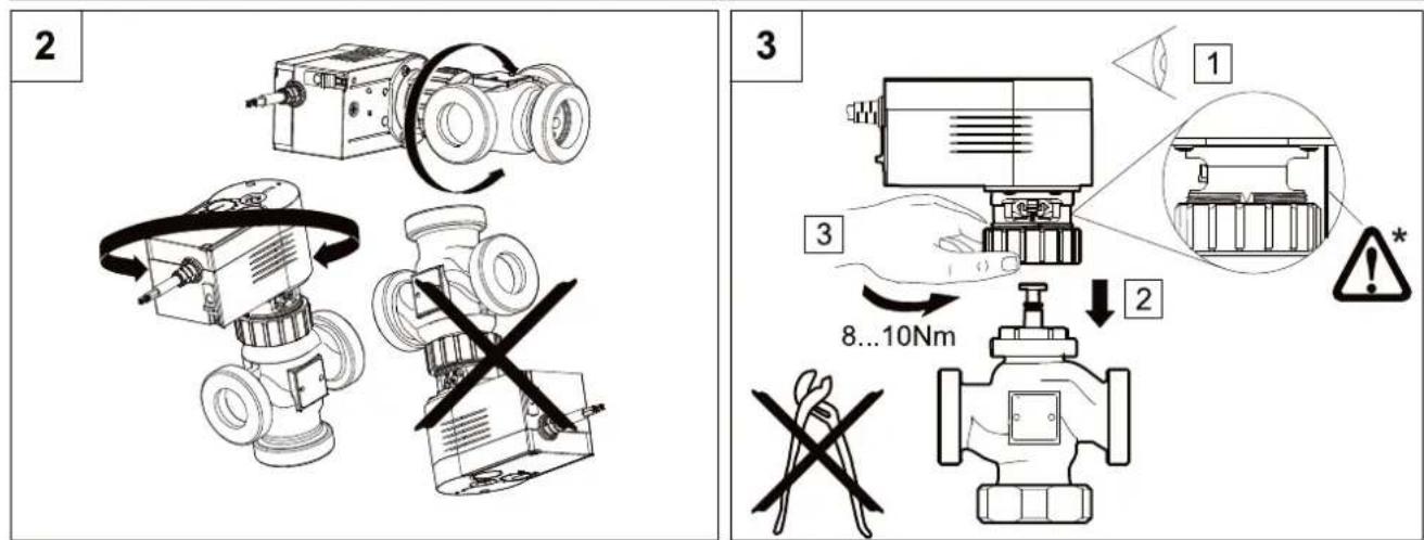
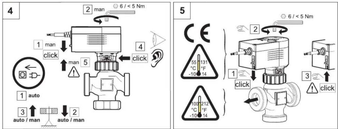
1.1 Assembling the reversal valve

Caution
- Never insulate
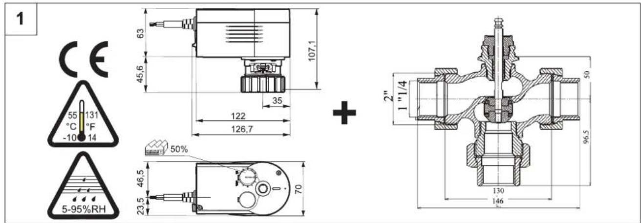
Fig.23
1.2 Hydraulic connection diagram
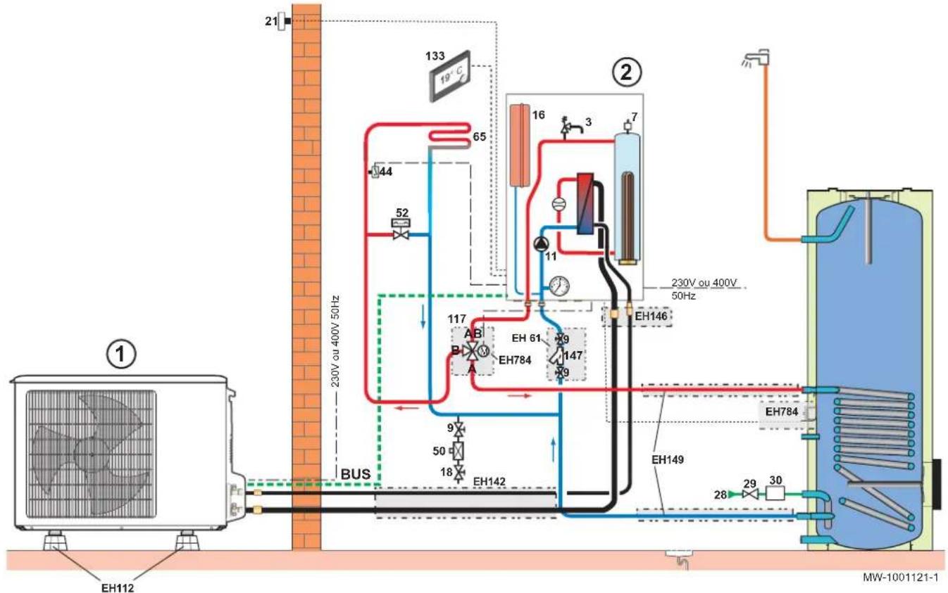
Fig.24
Tab.7
| Marker Description | |||
| 1 | Outdoor module 5 | 0 | Disconnector |
| 2 | Indoor module 5 | 2 | Differential valve |
| 3 | Safety valve 6 | $5 | Heating circuit with mixing valve, heating circuit which may be at low temperature (underfloor heating or radiators) |
| 7 | Automatic air vent 1 | 117 | Motorised reversal valve |
| 9 | Isolation valve 1 | 133 | Programmable digital room thermostat |
| 11 | Heating pump 1 | 147 | 400 μm hydraulic filter (mandatory) |
| 16 | Expansion vessel E | EH61 | 400 μm hydraulic filter + isolation valve |
| 18 | Heating circuit filling (France: with disconnector depending on regulations) | EH112 | Floor installation base |
| 21 | Outside temperature sensor E | EH142 | Refrigeration connection kit 1/2"- 1/4" - length 10 m |
| 28 | Domestic cold water inlet E | EH146 | Adapter fitting 1/2"- 1/4" to 5/8"- 3/8" |
| 29 | Pressure reducer E | EH149 | Hydraulic connection kit for the heat pump and the domestic hot water tank |
| 30 | Safety unit calibrated to 7 bar E | EH784 | Reversal valve and domestic hot water sensor |
| 44 | 65 °C safety thermostat | ||
1.3 Identifying the PCB used
Depending on the PCB used, there are two ways to install this kit.
- Access the PCB for the indoor module.
- Identifying the PCB version used:
| Version Image of the PCB See | ||
| 1 | MW-1001091-1 | Chapter 1.4 |
| 2 | MW-1001092-1 | Chapter 1.5 |
1.4 Indoor module with PCB - version 1
Fig.25
MW-1001125-1
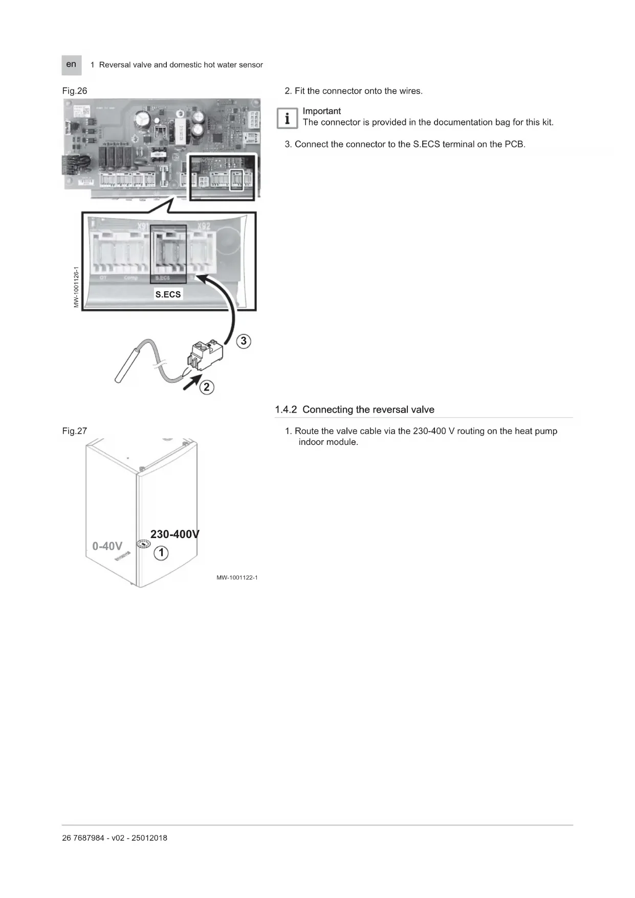
1.4.1 Connecting the domestic hot water sensor
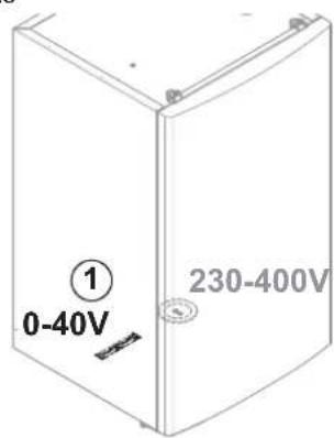
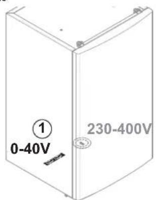
- Route the domestic hot water sensor cable via the 0-40 V routing on the heat pump indoor module.
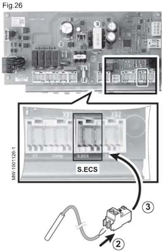
- Fit the connector onto the wires.
i Important The connector is provided in the documentation bag for this kit.
3. Connect the connector to the S.ECS terminal on the PCB.
1.4.2 Connecting the reversal valve
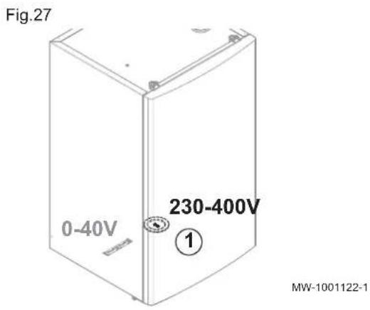
- Route the valve cable via the 230-400 V routing on the heat pump indoor module.
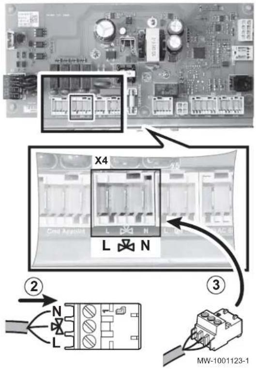
Fig.28
- Fit the connector onto the wires.

Black: control voltage

Brown: continuous voltage

Blue: neutral

Important
The connector is provided in the documentation bag for this kit.
- Connect the connector to the X4 terminal on the PCB.
1.4.3 Setting the control system
The information and settings in the Installer menu can only be accessed by a qualified professional.
- Set the P21 parameter to 1 in the fmenu.
- Select the correct operating mode for the installation by pressing the key twice.

See
Heat pump installation manual.
1.5 Indoor module with PCB - version 2
Fig.29
MW-1001125-1
1.5.1 Connecting the domestic hot water sensor
- Route the domestic hot water sensor cable via the 0-40 V routing on the heat pump indoor module.
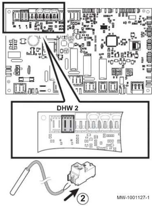
Fig.30
- Fit the connector onto the wires.

Important
The connector is fitted on the PCB.
In this case, the connectors supplied in the documentation bag are not necessary.
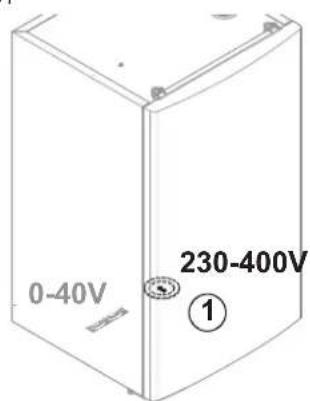
Fig.31
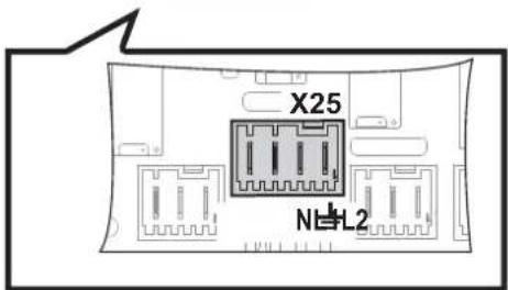
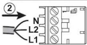
1.5.2 Connecting the reversal valve
- Route the valve cable via the 230-400 V routing on the heat pump indoor module.
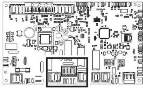
Fig.32
MW-1001124-1
2. Fit the connector onto the wires.
L1 Black: control voltage
L2 Brown: continuous voltage
N Blue: neutral
Important
The connector is fitted on the PCB.
In this case, the connectors supplied in the documentation bag are not necessary.
1.5.3 Setting the control system
When the installation is first switched on, refer to the chapter "Using the installation assistant for the control panel" in the Installation Manual for the heat pump.
- Select the desired installation type:
Tab.8
| Installation type No. | |
| 1 direct heating circuit and 1 domestic hot water tank | 02 |
| 1 direct heating circuit and 1 domestic hot water tank and 1 underfloor heating circuit with mixing valve | 04 |
| 1 direct underfloor heating circuit and 1 domestic hot water tank | 06 |

See
Heat pump installation manual.
1.6 Spare parts lists
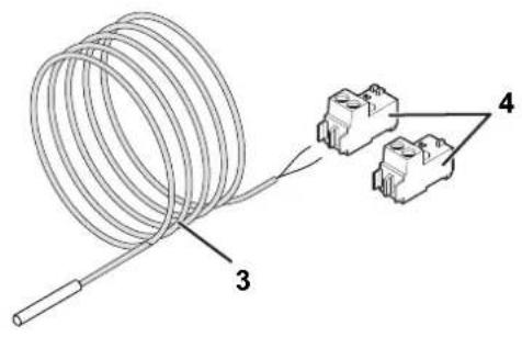
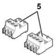
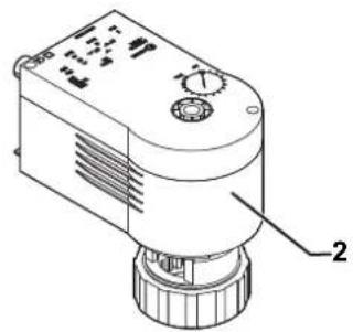
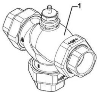
Fig.33
MW-1001128-1
Tab.9
| Marker Reference Description | |
| 1 300012321 Reversal valve | |
| 2 300012320 Reversal valve motor | |
| 3 95362448 KVT60 sensor, length 5m | |
| 4 300021727 RAST 5 sensor connector or - X2 - for PCB version 1 | |
| 4 300008957 RAST 5 sensor connector or - X2 - for PCB version 2 - EHC | |
| 5 300021723 RAST 5 connector - x4 - for three-way valve - for PCB version 1 | |
| 5 7685026 RAST 5 connector - x4 - for three-way valve - for PCB version 2 - EHC |
Inhoudsopgave
1 Omkeerklep en sensor sanitair warm water 33