HD 7164 Cage Classic - Pressure washer Kärcher - Free user manual and instructions
Find the device manual for free HD 7164 Cage Classic Kärcher in PDF.
User questions about HD 7164 Cage Classic Kärcher
0 question about this device. Answer the ones you know or ask your own.
Ask a new question about this device
Download the instructions for your Pressure washer in PDF format for free! Find your manual HD 7164 Cage Classic - Kärcher and take your electronic device back in hand. On this page are published all the documents necessary for the use of your device. HD 7164 Cage Classic by Kärcher.
USER MANUAL HD 7164 Cage Classic Kärcher
natural_image
Technical line drawing of a professional automatic pressure pump unit (no text or symbols)Deutsch 4
English 15
Français 26
Español 38
Svenska 50
Русский 61
Eesti 75
Latviešu 85
Lietuviškai 96
Українська 107
Português do 119
Brasil
Indonesia 131
한국어 143
中文 153
台灣語 162
Bahasa Melayu 171
ไทย 183

203
Register and win! www.kaercher.com/register-and-win
EAC

59675970 01/17
1
text_image
Technical diagram of a gas pump assembly with numbered parts and exploded view, including internal components and component labels.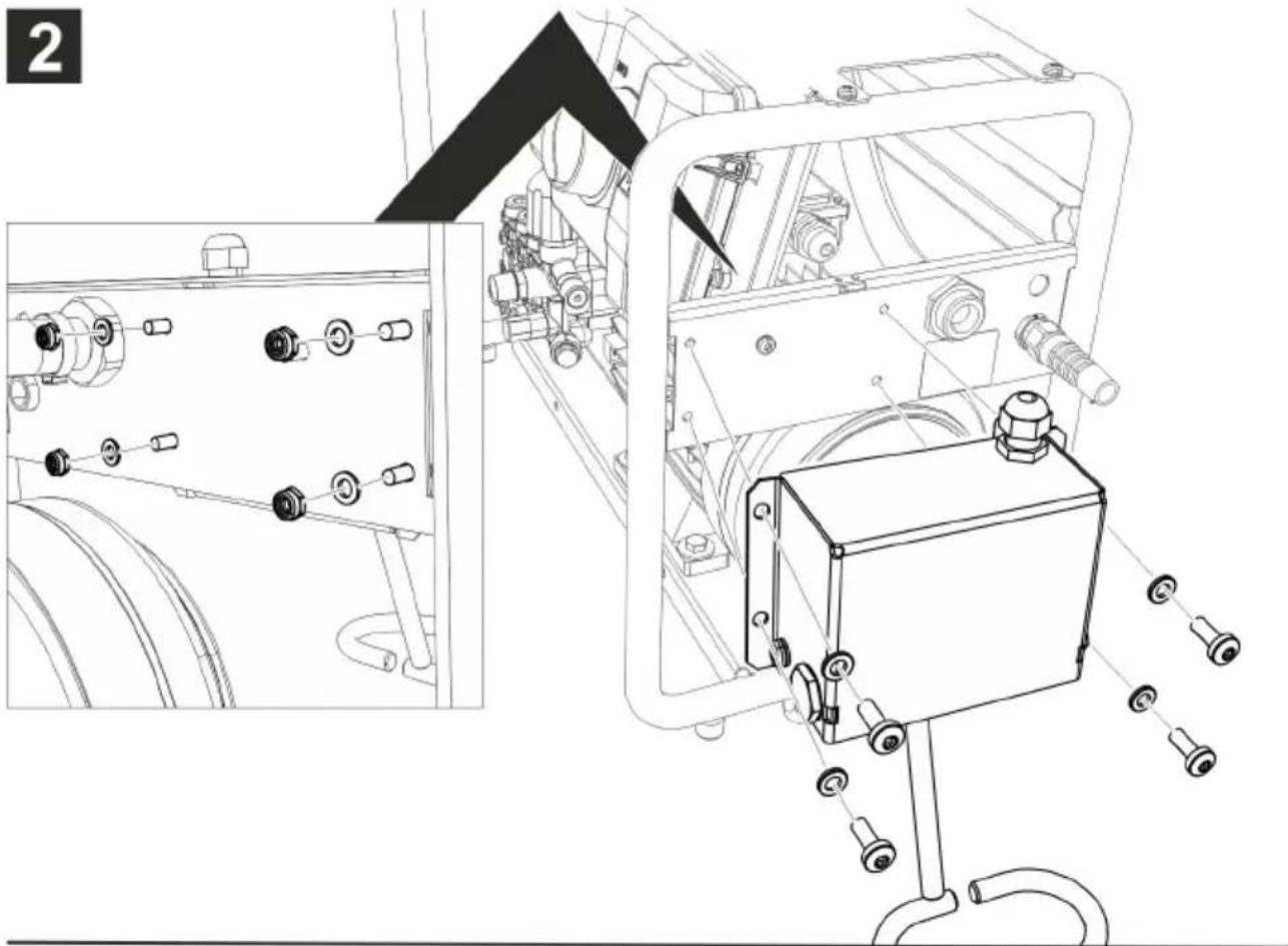
natural_image
Technical line drawing of a mechanical assembly with components and a close-up inset showing internal wiring (no text or symbols)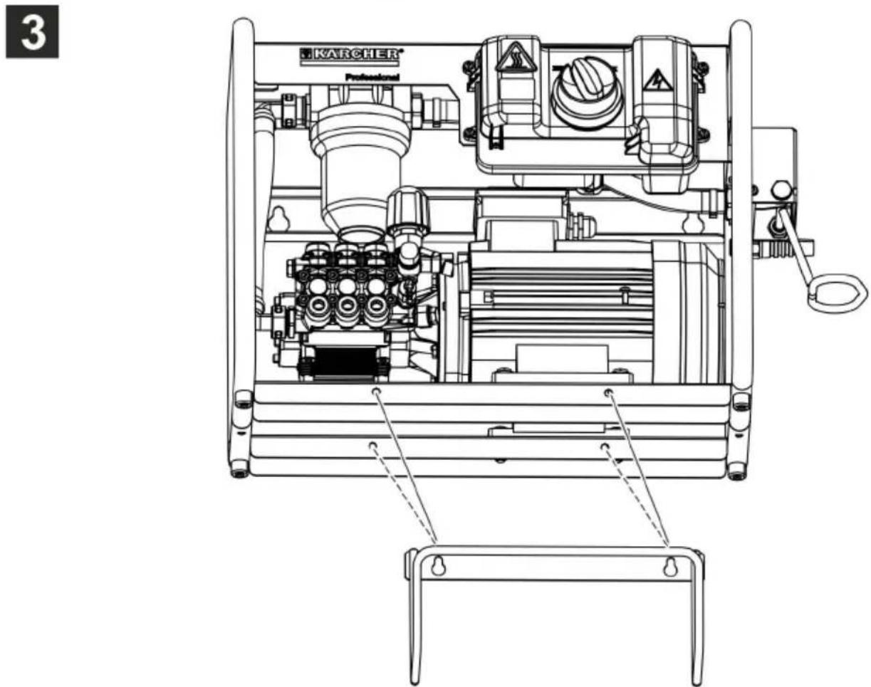
text_image
3 KARCHER Professional
natural_image
Technical diagram of a mechanical assembly with directional arrows indicating motion or force (no text or symbols present)text_image
Technical diagram showing two mechanical assembly steps with numbered annotations indicating component placement.
S. Reiser
Head of Approbation
71364 Winnenden (Germany)
Tel.: +49 7195 14-0
Fax: +49 7195 14-2212
Winnenden, 2017/01/01
Technische Daten
Please read and comply with these original instructions prior
to the initial operation of your appliance and store them for later use or subsequent owners.
Contents
| Device elements | EN 1 |
| Safety instructions. | EN 1 |
| Proper use | EN 4 |
| Safety Devices | EN 5 |
| Environmental protection | EN 5 |
| Before Startup. | EN 5 |
| Start up | EN 6 |
| Operation | EN 7 |
| Transport. | EN 8 |
| Storage | EN 8 |
| Care and maintenance | EN 8 |
| Troubleshooting | EN 9 |
| Accessories and Spare Parts | EN 9 |
| Warranty | EN 10 |
| EU Declaration of Conformity | EN 10 |
| Technical specifications | EN 10 |
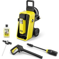
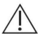
Device elements
Please unfold the front picture side Illustration 1
1 Power switch
2 Water connection
3 Mains cable with mains plug
4 Holder for trigger gun (equipment depending on the unit model)
5 Thermostat valve
6 Safety valve
7 High-pressure connection EASY!Lock
8 Pressure and volume regulation
9 Oil drain screw
10 Oil level indicator
11 Oil fill screw
12 Water filter
13 Nozzle screws
14 Nozzle
15 Spray lance EASY!Lock
16 Trigger gun EASY!Force
17 Safety catch
18 Trigger
19 Safety lever
20 High pressure hose EASY!Lock
21 Cable/hose storage
Safety instructions
- Please read the operating instructions for your machine before using it, and pay particular attention to the following safety instructions.
- Warning and information plates on the machine provide important directions for safe operation.
– Apart from the notes contained herein the general safety provisions and rules for the prevention of accidents of the legislator must be observed. - The appliance/accessories must not be modified.
Symbols in the operating instructions
⚠️DANGER
Pointer to immediate danger, which leads to severe injuries or death.
⚠ WARNING
Pointer to a possibly dangerous situation, which can lead to severe injuries or death.
△CAUTION
Pointer to a possibly dangerous situation, which can lead to minor injuries.
ATTENTION
Pointer to a possibly dangerous situation, which can lead to property damage.
Symbols on the machine
High-pressure jets can be dangerous if improperly used. The jet may not be directed at persons, animals, active electrical equipment or at the appliance itself.
According to applicable regulations, the appliance must never be used on the drinking water net without a system separator. A suitable system separator by Kärcher or alternatively a system separator according to EN 12729 type BA must be used.
Water that was flowing through a system separator is considered non-drinkable.
The appliance contains hot surfaces that can lead to burn injuries.
Risk of electric shock. The casing must only be opened by electricians.
Power connection
- The voltage indicated on the type plate must correspond to the voltage of the electrical source.
- Minimum fuse strength of the socket (see Technical Data).
- Safety class I - Appliances may only be connected to sockets with proper earthing.
- It is recommended that you connect this device to a socket that has a 30 mA protection switch against wrong currents.
- Please use the mains cable prescribed by the manufacturer; the same is also applicable when you replace the cables. See Operating Instructions Manual for Order Number and Type.
- Check the power cord with mains plug for damage before every use. If the power cord is damaged, please arrange immediately for the exchange by an authorized customer service or a skilled electrician.
- The appliance may only be connected to an electrical supply which has been installed by an electrician in accordance with IEC 60364.
- Operating procedures create short term power sinkings.
– During unfavorable net conditions other devices might be disturbed. - Never touch the mains plug with wet hands.
- Make sure that the power cord or extension cables are not damaged by running over, pinching, dragging or similar. Protect the cable from heat, oil, and sharp edges.
- The extension cable must have the cross-section listed in the circuit plan and be protected against spraying water. The connection must not lie in water.
- The mains plug and the coupling of an extension cable must be watertight and must never lie in water. Moreover, the coupling may never lie on the ground. The use of cable reels that ensure that the sockets are at least 60 mm above the ground is recommended.
- Unsuitable electrical extension cables can be hazardous. Only use electrical extension cables outdoors which have been approved and labelled for this purpose and have an adequate cable cross-section.
- The power cord must be checked regularly for damages, such as cracks or aging. If damage is found, the cable must be replaced before further use.
- If couplings of the power cord or extension cable are replace the splash protection and the mechanical tightness must be ensured.
- Do not clean the appliance with a water hose or high-pressure water jet (danger of short circuits or other damage).
- Do not operate the appliance at temperatures below 0 °C.
Water connection
- Please observe the safety instructions of your water supply authority.
- Please ensure that screw connections of all hoses are not leaky.
- The high pressure hose must not be damaged. A damaged high pressure hose must be replaced immediately. Only hoses and joints recommended by the manufacturer may be used. See Operating Instructions Manual for Order Number.
Application
- The appliance and its working equipment must be checked to ensure that it is in proper working order and is operating safely prior to use. The appliance must not be used if a connecting line or important parts of the appliance, e.g. safety devices, high-pressure hoses, spray guns, are damaged.
- Never draw in fluids containing solvents or undiluted acids and solvents! This includes petrol, paint thinner and heating oil. The spray mist thus generated is highly inflammable, explosive and poisonous. Do not use acetone, undiluted acids and solvents as they are aggressive towards the materials from which the appliance is made.
- If the appliance is used in hazardous areas (e.g. filling stations) the corresponding safety provisions must be observed. It is not allowed to use the appliance in hazardous locations.
- The appliance must be sitting on an even, stable ground.
- Wear ear plugs if the operating instructions of the appliance (Technical data) mention a noise level of more than 80 dB(A).
- All current-conducting parts in the working area must be protected against jet water.
- The lever of the hand spray gun must not be locked during the operation.
- Wear protective clothing and safety goggles to protect against splash back containing water or dirt.
- High-pressure jets can be dangerous if improperly used. The jet may not be directed at persons, animals, live electrical equipment or at the appliance itself.
- The jet must not be directed at other persons or directed by the user at him/herself to clean clothing or footwear.
- Vehicle tyres/ tyre valves may be cleaned only with a minimum spray distance of 30 cm. Otherwise, the high pressure spray can cause damage to the vehicle tyre/ tyre valve. The discolouring of the tyre is the first sign of damage. Damaged vehicle tyres are a source of danger.
- Do not spray materials containing asbestos or other health-hazardous substances.
- With short spray lances, there is a risk of injury, as a hand can accidentally come in contact with the high pressure
jet. If the spray lance is shorter than 75 cm, you must not use a point spray nozzle or a rotor nozzle.
- Prior to cleaning, a risk assessment must be performed for the surface to be cleaned to determine the safety and health requirements. The respective required protective measures must be taken.
- Let the hoses cool off after hot water operation or operate the appliance briefly using cold water.
- In case of extended downtimes, switch the appliance off at the main switch / appliance switch or remove the mains plug.
Operations
- The operator must use the appliance properly. The person must consider the local conditions and must pay attention to third parties, in particular children, when working with the appliance.
- Never leave the machine unattended so long as it is running.
- The appliance may only be used by persons who have been instructed in handling the appliance or have proven qualification and expertise in operating the appliance or have been explicitly assigned the task of handling the appliance. The appliance must not be operated by children, young persons or persons who have not been instructed accordingly.
- This appliance is not intended for use by persons with reduced physical, sensory or mental capabilities.
- The appliance must not be operated by children or persons who have not been instructed accordingly.
- Do not use the appliance when there are other persons around unless they are also wearing safety gear.
- Children should be supervised to prevent them from playing with the appliance.
-
Always use appropriate gloves while working on the device.
-
There is a recoil pressure arising from the water jet that comes out from the spray pipe. The angular spray pipe brings about an upward force. Hold the gun and the spray pipe tightly.
- The recoil and bending forces may be different if you are using angular spray devices.
Transport
The engine is to be brought to a standstill and the appliance is to be fastened properly during transportation.
Maintenance
- Switch off the appliance and, in case of appliances connected to the mains, pull out the power cord before cleaning and performing any maintenance tasks on the machine.
- Relieve the high pressure system of all pressure prior to all work on the appliance and the accessories.
- Maintenance work may only be carried out by approved customer service outlets or experts in this field who are familiar with the respective safety regulations.
- Mobile industrial appliances are subject to safety inspections according to the local regulations (for e.g. the following are applicable in Germany: VDE 0701).
Accessories and Spare Parts
- To avoid risks, all repairs and replacement of spare parts may only be carried out by the authorised customer service personnel.
- Only use accessories and spare parts which have been approved by the manufacturer. The exclusive use of original accessories and original spare parts ensures that the appliance can be operated safely and trouble free.
Proper use
Use this high pressure cleaner exclusively for
- cleaning with a high pressure jet without detergent (e.g. cleaning of facades, terraces, garden appliances, vehicles and similar objects).
For stubborn dirt, we recommend the use of the dirt blaster as a special accessory.
Quality requirements for water: ATTENTION
Only clean water may be used as high pressure medium. Impurities will lead to increased wear and tear or formation of deposits in the appliance.
If recycled water is used, the following limit values must not be exceeded.
| pH value 6,5...9,5 | |
| electrical conductivity * Conductivity fresh water +1200 μS/cm | |
| settleable solids ** < 0,5 mg/l | |
| total suspended solids *** < Hydrocarbons < 20 mg/l | 50 mg/l |
| Chloride < 300 mg/l | |
| Sulphate < 240 mg/l | |
| Calcium < 200 mg/l | |
| Total hardness < 28 °dH | < 50 °TH< 500 ppm (mg CaCO_3 /l) |
| Iron < 0,5 mg/l | |
| Manganese < 0,05 mg/l | |
| Copper < 2 mg/l | |
| Active chloride < 0,3 mg/l | |
| free of bad odours | |
| * Maximum total 2000 μS/cm** Test volume 1 l, settling time 30 min*** no abrasive substances | |
Safety Devices
Safety devices serve to protect the user and must not be rendered in operational or their functions bypassed.
Overflow valve
- While reducing the water supply/quantity regulation at the pump head, the overflow valve opens and part of the water flows back to the pump suck side.
- If the hand spray gun is closed, the overflow valve opens and the entire water volume will flow back to the pump suction side.
The overflow valve is set by the manufacturer and sealed. Setting only by customer service.
Safety valve
The safety valve opens when the overflow valve is defective.
The safety valve is set by the manufacturer and sealed. Setting only by customer service.
Thermostat valve
The thermal valve protects the high-pressure pump from unacceptable heating during circuit operation.
Environmental protection

The packaging material can be recycled. Please do not place the packaging into the ordinary refuse for disposal, but arrange for the proper recycling.
Old appliances contain valuable materials that can be recycled. Please arrange for the proper recycling of old appliances. Batteries and accumulators contain substances that must not enter the environment. Please dispose of your old appliances, batteries and accumulators using appropriate collection systems.
Electrical and electronic devices often contain components which could potentially pose a danger to human health and the environment if handled or disposed of incorrectly. However, these components are necessary for the proper operation of the device. Devices marked with this symbol must not be disposed of with regular household rubbish.
Notes about the ingredients (REACH)
You will find current information about the ingredients at:
www.kaercher.com/REACH
Before Startup
Unpacking
- Check the contents of the pack before unpacking.
– In case of transport damage inform vendor immediately.
Check oil level
→ The oil level must be at the centre of the oil level display.
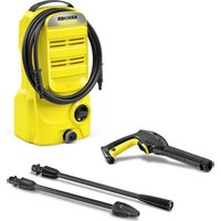
Activate deaeration of oil container
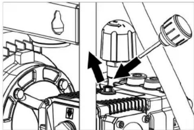
natural_image
Technical diagram of a mechanical assembly with directional arrows indicating motion or movement (no text or symbols present)→ Unscrew the screw plug.
→ Screw in enclosed oil filling screw.
→ Close cover.
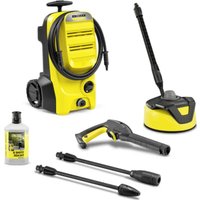
Install hand spray gun, spray lance and nozzle
Note: The EASY!Lock system joins components with a quick-fasten thread solidly and securely with just one turn.
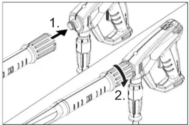
text_image
Technical diagram showing two mechanical assembly steps with labeled components and directional arrows indicating movement or assembly.→ Insert the high pressure nozzle onto the spray lance.
→ Install union nut and hand-tighten it (EASY!Lock).
→ Join the spray lance with the trigger gun and tighten until hand-tight (EASY!Lock).
→ Join the high-pressure hose with trigger gun and high-pressure connection of the appliance and tighten until hand-tight (EASY!Lock).
Mounting the cable / hose rack
→ If required, attach accompanying cable / hose rack to the wall.
or
Illustration 3
→ Attach the enclosed cable/hose rack to the bottom of the device.
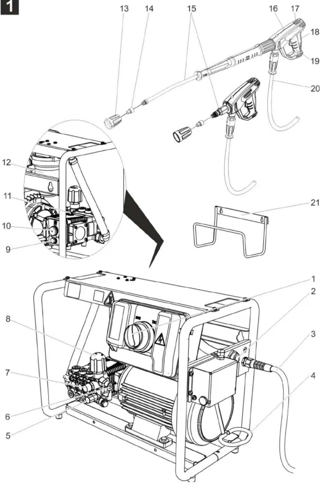
Attaching the holder for the trigger gun
Note:
Not all unit models are equipped with the holder for the trigger gun.
Illustration 2
→ Attaching the support.
Start up
⚠️DANGER
Risk of injury! Device, tubes, high pressure hose and connections must be in faultless condition. If they are not in a perfect state then the appliance must not be used.
Electrical connection
⚠️DANGER
Danger of injury by electric shock.
The appliance may only be connected to alternating current.
It is imperative to connect the appliance to the electric mains by means of a plug. It is forbidden to permanently connect the appliance to the power supply. The plug serves for the disconnection from the mains.
Use the extension cord that has an adequate cross-section (see "Technical Data") and unwind it fully from the cable drum.
For connection values, see type plate/technical data.
Water connection
Connection to the water supply
According to applicable regulations, the appliance must never be used on the drinking water net without a system separator. Ensure that the connection of your building water installation on which the high-pressure cleaner is operated is equipped with a system separator pursuant to EN 12729 Type BA.
Water that was flowing through a system separator is considered non-drinkable.
△CAUTION
Always connect the system separator to the water supply, never directly to the appliance!
For connection values refer to technical specifications.
→ Connect the supply hose (minimum length 7.5 m, minimum diameter 3/4") to the water connection point of the machine and at the water supply point (for e.g. a tap).
Note:
The supply hose is not included.
→ Open the water supply.
Drawing in water from open reservoirs
→ Screw the suction hose onto the water connection.
Note:
The suction hose is not included in the scope of delivery.
If a suction hose with a check valve or filter is used, the hose must be filled with water.
→ Deaerate the appliance:
Unscrew the nozzle.
Switch on the appliance and let it run until the water exiting is bubble-free.
At the end let the appliance run for approx. 10 seconds - then switch off. Repeat the procedure for a couple of times.
→ Switch off the appliance and fit the nozzle again.
Operation
⚠️DANGER
Risk of explosion!
Do not spray flammable liquids.
If the appliance is used in hazardous areas (e.g. filling stations) the corresponding safety regulations must be observed.
Risk of injury! Hold the hand spray gun and the spray pipe firmly with both hands.
Risk of injury! The trigger and safety lever may not be locked during the operation.
Risk of injury! Contact Customer Service if the safety lever is damaged.
Risk of injury from high-pressure water jet. Slide the safety catch on the trigger gun forward before performing any work with the appliance.
ATTENTION
Clean engines only at places with corresponding oil separators (environmental safety).
Opening/closing the trigger gun
→ To open the trigger gun: Actuate the safety lever and trigger.
→ To close the hand spray gun: Release the safety lever and trigger.
High pressure operation
Appliance with holder for trigger gun:
→ Set the appliance switch to "I".
→ Remove the hand spray gun from the holder, the appliance switches on.
→ Release the trigger gun. To do so, push the safety catch towards the back.
→ Open the hand spray gun.
→ Set working pressure and flow rate through turning (runless) at the pressure- and amount regulation (B) (+/-).
Set the appliance switch to "I". The appliance switches on.
Appliance without holder for trigger gun:
Interrupting operation
→ Close the hand spray gun.
The appliance switches off.
→ Secure the trigger gun. To do so, push the safety catch towards the front.
After the interruption:
→ Release the trigger gun. To do so, push the safety catch towards the back.
→ Open the hand spray gun.
The appliance will switch on again.
Interrupting operation
Short break
→ Close the hand spray gun.
The pump continues to run in circulation mode.
→ Open the hand spray gun.
Circuit operation is ended.
Longer break
→ Close the hand spray gun.
→ Push the safety catch on the trigger gun forwards slightly.
Appliance with holder for trigger gun:
→ Place the trigger gun into the holder. The pump stops.
→ Remove trigger gun from the holder.
The pump starts.
Appliance without holder for trigger gun:
→ Set the appliance switch to "0/OFF". The pump stops.
→ Set the appliance switch to "I". The pump starts.
→ Release the trigger gun. To do so, push the safety catch towards the back.
→ Open the hand spray gun.
Turn off the appliance
→ Shut off water supply.
→ Open the hand spray gun.
→ Switch on the pump with the power switch and allow to run for about 5-10 seconds.
→ Close the hand spray gun.
→ Set the appliance switch to "0/OFF".
→ Pull main plug out of socket with dry hands only.
→ Activate hand spray gun until device is pressure less.
→ Secure the trigger gun. To do so, push the safety catch towards the front.
Frost protection
ATTENTION
Frost will destroy the not completely water drained device.
Store the appliance in a frost free area.
If you cannot store it in a frost-free place:
→ Drain water.
→ Pump in conventional frost protection agents through the appliance.
Note:
Use normal glycol-based anti-freezing agents for automobiles.
Observe handling instructions of the anti-freeze agent manufacturer.
→ Operate device for max. 1 minute until the pump and conduits are empty.
Transport
→ When transporting in vehicles, secure the appliance according to the guidelines from slipping and tipping over.
△CAUTION
Risk of personal injury or damage! Mind the weight of the appliance during transport.
ATTENTION
Protect the trigger from damage during transport.
Storage
△CAUTION
Risk of personal injury or damage! Consider the weight of the appliance when storing it.
Care and maintenance
⚠️DANGER
Risk of injury by inadvertent startup of appliance and electrical shock.
Prior to all work on the appliance, switch off the appliance and pull the power plug.
Note:
Used oil must only be disposed of by the designated collection points. Please turn in used oil there. Polluting the environment with used oil is prosecutable.
Safety inspection/ maintenance contract
You can sign with your dealer a contract for regular safety inspection or even sign a maintenance contract. Please take advice on this matter.
Before each use
→ Check connection cable for damages (risk of electrical shock); get the damaged connection cable replaced immediately by an authorised customer service person/ electrician.
→ Check the high pressure hose for damages (risk of bursting).
Please arrange for the immediate exchange of a damaged high-pressure hose.
→ Check appliance (pump) for leaks.
3 drops per minute are permitted and can come out from the lower side of the appliance. Call Customer Service if there is heavy leakage.
Weekly
→ Check oil level Please contact Customer Service immediately if the oil is milky (water in oil).
→ Clean water filter.
Every 500 operating hours, at least annually
→ Have the maintenance of the device performed by the customer service.
→ Oil change.
Oil change
Note:
See "Specifications" for oil volume and type.
→ Unscrew oil drain plug.
→ Drain the oil in a collection basin.
→ Fix in the oil drain screw and tighten it. Torque 20...25 Nm.
→ Turn the oil fill screw out.
→ Fill in new oil slowly; air bubbles should go out.
The oil level must be at the centre of the oil level display.
→ Screw in oil filling screw.
→ Close cover.
Troubleshooting
⚠️DANGER
Risk of injury by inadvertent startup of appliance and electrical shock.
Prior to all work on the appliance, switch off the appliance and pull the power plug.
Get the electrical components checked and repaired only by authorised customer service persons.
Contact an authorised customer service person in case of problems not mentioned in this chapter or if you are in doubt or when you have been explicitly asked to do so.
Appliance is not running
→ Only with appliances with holder for trigger gun: Do not push down the holder.
→ Check connection cable for damages.
→ Check the supply voltage.
→ Call Customer Service in case of electrical defects.
Pressure does not build up in the appliance
→ Set the pressure and quantity regulation to "MAX".
→ Check the nozzle size, install correct nozzle.
→ Clean the nozzle.
→ Replace the nozzle.
→ Deaerate the appliance (see "Start-up")
→ Check water supply level (refer to technical data).
→ Clean water filter.
→ Check all inlet pipes to the pump.
→ Contact Customer Service if needed.
Pump leaky
3 drops per minute are permitted and can come out from the lower side of the appliance. Call Customer Service if there is heavy leakage.
→ With stronger leak, have device checked by customer service.
Pump is vibrating
→ Clean water filter.
→ Check the water suction pipes for leaks.
→ Deaerate the appliance (see "Start-up")
→ Contact Customer Service if needed.
Water leak on the thermovalve
This function is not a fault. If the appliance becomes too hot in the circulation mode, the thermovalve opens so that cold water can flow in.
Water leak at the safety valve
→ Turn off the appliance, wait briefly, turn on the appliance once again.
→ If the fault appears again afterwards, do no longer use the appliance. Have the device checked by aftersales service.
Accessories and Spare Parts
Only use original accessories and spare parts, they ensure the safe and trouble-free operation of the device.
For information about accessories and spare parts, please visit www.kaercher.com.
Warranty
The warranty terms published by the relevant sales company are applicable in each country. We will repair potential failures of your appliance within the warranty period free of charge, provided that such failure is caused by faulty material or defects in manufacturing. In the event of a warranty claim please contact your dealer or the nearest authorized Customer Service centre. Please submit the proof of purchase.
EU Declaration of Conformity
We hereby declare that the machine described below complies with the relevant basic safety and health requirements of the EU Directives, both in its basic design and construction as well as in the version put into circulation by us. This declaration shall cease to be valid if the machine is modified without our prior approval.
Product: High pressure cleaner
Type: 1.367-xxx
Relevant EU Directives
2006/42/EC (+2009/127/EC)
2014/30/EU
2000/14/EC
2011/65/EU
Applied harmonized standards
EN 60335-1
EN 60335-2-79
EN 55014-1: 2006+A1: 2009+A2: 2011
EN 55014-2: 2015
EN 62233: 2008
EN 61000-3-2: 2006+A1: 2009+A2: 2009
EN 61000-3-11:2000
EN 50581
Applied conformity evaluation method
2000/14/EC: Appendix V
Sound power level dB(A)
Measured: 87
Guaranteed: 90
The undersigned act on behalf and under the power of attorney of the company management.

CEO

S. Reiser
Head of Approbation
Authorised Documentation Representative S. Reiser
71364 Winnenden (Germany)
Phone: +49 7195 14-0
Fax: +49 7195 14-2212
Winnenden, 2017/01/01
Technical specifications
| Type HD 7/16-4 | ||
| Main Supply | ||
| Voltage V 380...415 | ||
| Current type Hz 3~50 | ||
| Connected load kW 4.3 | ||
| Protection (slow, char. C) A 16 | ||
| Type of protection -- IPX5 | ||
| Extension cord 30 m mm | 2 | 2.5 |
| Water connection | ||
| Max. feed temperature °C 60 | ||
| Min. feed volume l/h (l/min) 1000 (16,67) | ||
| Suck height from open container (20 °C) m | 0.5 | |
| Max. feed pressure | MPa (bar) | 1.0 (10) |
| Performance data | ||
| Operating pressure of water (using standard nozzle) | MPa (bar) | 7...16 (70...160) |
| Max. operating over-pressure | MPa (bar) | 25 (250) |
| Size of standard nozzle | -- 040 | |
| Flow rate | l/h (l/min) 400 | ...700(6.7...11.71) |
| Max. recoil force of trigger gun | N | 35 |
| Values determined as per EN 60335-2-79 | ||
| Hand-arm vibration value | m/s2 | <2.5 |
| Uncertainty K | m/s2 | 0.6 |
| Sound pressure level LpA | dB(A) | 87 |
| Uncertainty KpA | dB(A) | 3 |
| Sound power level LWA + Uncertainty KWAA | dB(A) | 90 |
| Fuel | ||
| Amount of oil | I | 0.4 |
| Oil grade | -- 15W40 | |
| Dimensions and weights | ||
| Length | mm | 780 |
| Width | mm | 360 |
| Height | mm | 500 |
| Weight, ready to operate with accessories | kg | 56.5 |

www.kaercher.com/REACH
natural_image
Technical diagram of a mechanical assembly with directional arrows indicating movement or force (no text or symbols present)text_image
Technical diagram showing two mechanical assembly steps with numbered components and directional arrows indicating assembly direction.2006/42/CE (+2009/127/CE)
2014/30/UE
2000/14/CE
2011/65/UE
71364 Winnenden (Germany)
www.kaercher.com/REACH
natural_image
Technical diagram of a mechanical assembly with directional arrows indicating motion or force (no text or symbols present)text_image
Technical diagram showing two mechanical assembly steps with numbered components and directional arrows indicating assembly direction.2006/42/CE (+2009/127/CE)
2014/30/UE
2000/14/CE
2011/65/UE
71364 Winnenden (Germany)
Tele.: +49 7195 14-0
Fax: +49 7195 14-2212
Winnenden, 2017/01/01
Datos técnicos
www.kaercher.com/REACH
Före ibruktagande
Uppackning
natural_image
Technical diagram of a mechanical assembly with directional arrows indicating motion or movement (no text or symbols present)text_image
Technical diagram showing two mechanical assembly steps with numbered annotations indicating component placement.
S. Reiser
Head of Approbation
71364 Winnenden (Germany)
Tel.: +49 7195 14-0
Fax: +49 7195 14-2212
Winnenden, 2017/01/01
Tekniska data
www.kaercher.com/REACH
natural_image
Technical diagram of a mechanical assembly with directional arrows indicating movement or force (no text or symbols present)text_image
Technical diagram showing two mechanical assembly steps with numbered annotations indicating component placement.
S. Reiser
Head of Approbation
71364 Winnenden (Germany)
Тел.: +49 7195 14-0
Факс: +49 7195 14-2212
www.kaercher.com/REACH
natural_image
Technical diagram of a mechanical assembly with directional arrows indicating movement or force (no text or symbols present)text_image
Technical diagram showing two mechanical assembly steps with numbered components and directional arrows indicating assembly direction.Toode: Körgsurvepesur
Tüüp: 1.367-xxx

S. Reiser
Head of Approbation
71364 Winnenden (Germany)
Tel: +49 7195 14-0
Winnenden, 2017/01/01
Tehnilised andmed
www.kaercher.com/REACH
natural_image
Technical diagram of a mechanical assembly with directional arrows indicating motion or movement (no text or symbols present)text_image
Technical diagram showing two mechanical assembly steps with numbered annotations indicating component placement.
S. Reiser
Head of Approbation
71364 Winnenden (Germany)
Tālr.: +49 7195 14-0
Fakss: +49 7195 14-2212
Vinendene (Winnenden), 2017/01/01
Tehniskie dati
www.kaercher.com/REACH
Prieš pradedant naudoti
Išpakavimas
natural_image
Technical diagram of a mechanical assembly with directional arrows indicating movement or force (no text or symbols present)text_image
Technical diagram showing two mechanical assembly steps with numbered annotations indicating component placement.71364 Winnenden (Germany)
Tel.: +49 7195 14-0
Faksas: +49 7195 14-2212
Vinendenas, 2017-01-01
Techniniai duomenys
www.kaercher.com/REACH
natural_image
Technical diagram of a mechanical assembly with directional arrows indicating motion or movement (no text or symbols present)text_image
Technical diagram showing two mechanical assembly steps with numbered annotations indicating component placement.
S. Reiser
Head of Approbation
71364 Winnenden (Germany)
Тел.: +49 7195 14-0
Факс: +49 7195 14-2212
www.kaercher.com/REACH
natural_image
Technical diagram of a mechanical assembly with directional arrows indicating movement or force (no text or symbols present)→ Desenroscar o parafuso de fecho.
→ Enroscar o parafuso de enchimento do óleo fornecido.
→ Fechar a tampa do aparelho.
text_image
Technical diagram showing two mechanical assembly steps with numbered components and directional arrows indicating assembly direction.2006/42/CE (+2009/127/CE)
2014/30/EU
2000/14/CE
2011/65/UE
71364 Winnenden (Germany)
Tel.: +49 7195 14-0
Fax: +49 7195 14-2212
Winnenden, 2017/01/01
Dados técnicos
www.kaercher.com/REACH
natural_image
Technical diagram of a mechanical assembly with arrows indicating motion or force direction (no text or symbols present)text_image
Technical diagram showing two mechanical assembly steps with numbered labels indicating component identification.71364 Winnenden (Germany)
Tel.: +49 7195 14-0
Winnenden, 2017/01/01
Data Teknis
| Jenis HD 7/16-4 | ||
| Catu daya | ||
| Tegangan V 380...415 | ||
| Tipe arus listrik Hz 3~50 | ||
| Daya sambungan kW 4,3 | ||
| Perlindungan (inersia, Char. C) A 16 | ||
| Jenis pelindung -- IPX5 | ||
| Kabel ekstensi 30 m mm | 2 | 2,5 |
| Sambungan air | ||
| Temperatur masuk (maks.) °C 60 | ||
| Jumlah masuk (min.) l/h (l/min) 1000 (16,67) | ||
| Ketinggian penyedotan air dari tangki air yang terbuka (20 C) | m | 0,5 |
| Tekanan masuk (maks.) | MPa (bar) | 1,0 (10) |
| Data kinerja | ||
| Tekanan kerja air (dengan nosel standar) | MPa (bar) | 7...16 (70...160) |
| Tekanan lebih pengoperasian maks. | MPa (bar) | 25 (250) |
| Ukuran nozzle standar | -- 040 | |
| Volume pengiriman | l/h (l/min) 400 | ...700(6,7...11,71) |
| Kekuatan pantulan balik pistol penyemprot (maks.) | N | 35 |
| Penentuan nilai menurut EN 60335-2-79 | ||
| Nilai getaran tangan-lengan | m/s2 | <2,5 |
| Ketidakstabilan K | m/s2 | 0,6 |
| Tingkat tekanan suara LpA | dB(A) | 87 |
| Ketidakstabilan KpA | dB(A) | 3 |
| Tingkat kekuatan suara LWA + Ketidakstabilan KWA | dB(A) | 90 |
| Cairan pengoperasian | ||
| Jumlah oli l 0,4 | ||
| Tipe oli | -- 15W40 | |
| Berat dan Ukuran | ||
| Panjang | mm | 780 |
| Lebar | mm | 360 |
| Tinggi | mm | 500 |
| Berat, bersama dengan aksesoris | kg | 56,5 |
www.kaercher.com/REACH
작동 전
포장 풀기
-포장 풀 때 내용물을 검사합니다.
natural_image
Technical diagram of a mechanical assembly with directional arrows indicating motion or force (no text or symbols present)text_image
Technical diagram showing two mechanical assembly steps with numbered annotations indicating component placement.
S. Reiser
Head of Approbation
문서 피 위임자:
S. Reiser
Winnenden, 2017/01/01
기술 자료
www.kaercher.com/REACH
设备运作前
打开包装
natural_image
Technical diagram of a mechanical assembly with directional arrows indicating motion or force (no text or symbols present)text_image
Technical diagram showing two mechanical assembly steps with numbered callouts indicating component identification.71364 Winnenden (Germany)
电话:+49 7195 14-0
传真:+49 7195 14-2212
Winnenden, 2017/01/01
产品规格 / 参数
natural_image
Technical diagram of a mechanical assembly with directional arrows indicating movement or force (no text or symbols present)→ 旋出螺旋塞。
→ 旋入隨附之注油旋塞。
→ 關閉裝置蓋。
安裝手持式噴槍、噴射管和噴嘴
text_image
Technical diagram showing two mechanical assembly steps with numbered components and directional arrows indicating assembly direction.→ 將高壓噴嘴插到噴射管上。
71364 Winnenden (Germany)
電話:+49 7195 14-0
傳真:+49 7195 14-2212
溫嫩登,2017年1月1日
技術參數
www.kaercher.com/REACH
Sebelum Mula
Membuka Bungkusan
natural_image
Technical diagram of a mechanical assembly with directional arrows indicating motion or force (no text or symbols present)text_image
Technical diagram showing two mechanical assembly steps with numbered annotations indicating component placement.71364 Winnenden (Germany)
Telefon: +49 7195 14-0
Winnenden, 01/01/2017
natural_image
Technical diagram of a mechanical assembly with directional arrows indicating movement or force (no text or symbols present)text_image
Technical diagram showing two mechanical assembly steps with numbered annotations indicating component placement.Winnenden, 2017/01/01
ข้อมูลทางเทคนิค
natural_image
Technical diagram of a mechanical assembly with directional arrows indicating motion or movement (no text or symbols present)← ي الغلق.
← المرفق
← اع الجهاز.
text_image
Technical diagram showing two mechanical assembly steps with numbered annotations indicating component placement.www.kaercher.com/REACH
natural_image
Icon of a gear and wrench inside a square frame (no text or symbols)http://www.kaercher.com/dealersearch