HDS 716 CX - Pressure washer Kärcher - Free user manual and instructions
Find the device manual for free HDS 716 CX Kärcher in PDF.
Download the instructions for your Pressure washer in PDF format for free! Find your manual HDS 716 CX - Kärcher and take your electronic device back in hand. On this page are published all the documents necessary for the use of your device. HDS 716 CX by Kärcher.
USER MANUAL HDS 716 CX Kärcher
Register your product www.kaercher.com/welcome HDS 6/10 C HDS 6/12 C
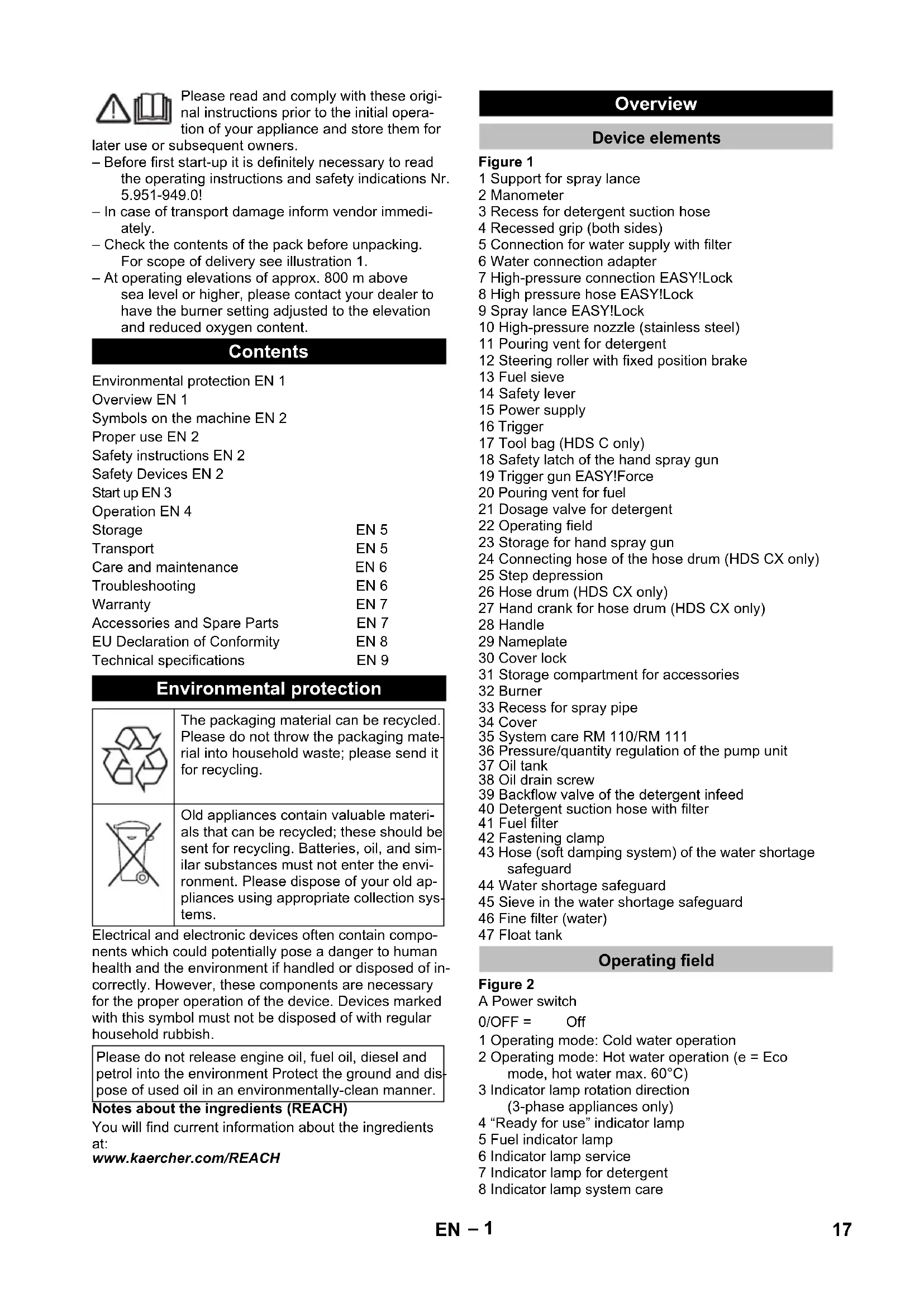
Typisches Betriebsgewicht, C kg 118,1 118,1 121,1 Typisches Betriebsgewicht, CX kg 121 121 124 Brennstofftank l 15,5 15,5 15,5 Reinigungsmitteltank l 15,5 15,5 15,5 16 DE– 1 Please read and comply with these origi- nal instructions prior to the initial opera- tion of your appliance and store them for later use or subsequent owners. – Before first start-up it is definitely necessary to read the operating instructions and safety indications Nr. 5.951-949.0! – In case of transport damage inform vendor immedi- ately. – Check the contents of the pack before unpacking. For scope of delivery see illustration 1. – At operating elevations of approx. 800 m above sea level or higher, please contact your dealer to have the burner setting adjusted to the elevation and reduced oxygen content. Electrical and electronic devices often contain compo- nents which could potentially pose a danger to human health and the environment if handled or disposed of in- correctly. However, these components are necessary for the proper operation of the device. Devices marked with this symbol must not be disposed of with regular household rubbish. Notes about the ingredients (REACH) You will find current information about the ingredients at: www.kaercher.com/REACH Figure 1 1 Support for spray lance 2 Manometer 3 Recess for detergent suction hose 4 Recessed grip (both sides) 5 Connection for water supply with filter 6 Water connection adapter 7 High-pressure connection EASY!Lock 8 High pressure hose EASY!Lock 9 Spray lance EASY!Lock 10 High-pressure nozzle (stainless steel) 11 Pouring vent for detergent 12 Steering roller with fixed position brake 13 Fuel sieve 14 Safety lever 15 Power supply 16 Trigger 17 Tool bag (HDS C only) 18 Safety latch of the hand spray gun 19 Trigger gun EASY!Force 20 Pouring vent for fuel 21 Dosage valve for detergent 22 Operating field 23 Storage for hand spray gun 24 Connecting hose of the hose drum (HDS CX only) 25 Step depression 26 Hose drum (HDS CX only) 27 Hand crank for hose drum (HDS CX only) 28 Handle 29 Nameplate 30 Cover lock 31 Storage compartment for accessories 32 Burner 33 Recess for spray pipe 34 Cover 35 System care RM 110/RM 111 36 Pressure/quantity regulation of the pump unit 37 Oil tank 38 Oil drain screw 39 Backflow valve of the detergent infeed 40 Detergent suction hose with filter 41 Fuel filter 42 Fastening clamp 43 Hose (soft damping system) of the water shortage safeguard 44 Water shortage safeguard 45 Sieve in the water shortage safeguard 46 Fine filter (water) 47 Float tank Figure 2 A Power switch 1 Operating mode: Cold water operation 2 Operating mode: Hot water operation (e = Eco mode, hot water max. 60°C) 3 Indicator lamp rotation direction (3-phase appliances only) 4 “Ready for use” indicator lamp 5 Fuel indicator lamp 6 Indicator lamp service 7 Indicator lamp for detergent 8 Indicator lamp system care Contents Environmental protection EN 1 Overview EN 1 Symbols on the machine EN 2 Proper use EN 2 Safety instructions EN 2 Safety Devices EN 2 Start up EN 3 Operation EN 4 Storage EN 5 Transport EN 5 Care and maintenance EN 6 Troubleshooting EN 6 Warranty EN 7 Accessories and Spare Parts EN 7 EU Declaration of Conformity EN 8 Technical specifications EN 9 Environmental protection The packaging material can be recycled. Please do not throw the packaging mate- rial into household waste; please send it for recycling. Old appliances contain valuable materi- als that can be recycled; these should be sent for recycling. Batteries, oil, and sim- ilar substances must not enter the envi- ronment. Please dispose of your old ap- pliances using appropriate collection sys- tems. Please do not release engine oil, fuel oil, diesel and petrol into the environment Protect the ground and dis- pose of used oil in an environmentally-clean manner. Overview Device elements Operating field 0/OFF = Off 17EN– 2 – The operating elements for the cleaning process are yellow. – The controls for the maintenance and service are light gray. High-pressure jets can be dangerous if im- properly used. The jet may not be directed at persons, animals, live electrical equip- ment or at the appliance itself. Cleaning of: Machines, Vehicles, Structures, Tools, Fa- cades, Terraces, Gardening tools, etc. DANGER Risk of injury! Follow the respective safety regulations when operating at gas stations or other dangerous are- as. Quality requirements for water: ATTENTION Only clean water may be used as high pressure medi- um. Impurities will lead to increased wear and tear or formation of deposits in the appliance and accessories. If recycled water is used, the following limit values must not be exceeded. – Please follow the national rules and regulations for fluid spray jets of the respective country. – Please follow the national rules and regulations for accident prevention of the respective country. Fluid spray jets must be tested regularly and the results of these tests must be documented in writing. – The heating appliance of the machine is an ignition plant. All national laws and regulations about heat- ing systems must also be followed. – The appliance/accessories must not be modified. Safety devices serve for the protection of the user and must not be put out of operation or bypassed with re- spect to their function. – While reducing the water supply at the pump head or with the Servopress - regulation the overflow valve opens and part of the water flows back to the pump suck side. – If the hand-spray gun is closed, so that the whole water flows back to the pump suck side, the pres- sure switch at the overflow valve shuts down the pump. – If the hand spray gun is opened, the pressure switch on the cylinder head turns the pump back on. The overflow valve is set by the manufacturer and sealed. Setting only by customer service. – The safety valve opens, when the overflow valve resp. the pressure switch is broken. The safety valve is set by the manufacturer and sealed. Setting only by customer service. – The water shortage safeguard prevents the burner to be turned on when there is water shortage. – A sieve prevents the contamination of the safe- guard and must be cleaned regular. – The temperature stop switches off the machine when the waste gases have reached very high tem- peratures. Colour coding Symbols on the machine Risk of electric shock! Only electricians or authorised techni- cians are permitted to work on parts of the plant. Risk of burns on account of hot surfaces! Risk of poisoning! Do not inhale exhaust fumes. Proper use Please do not let mineral oil contaminated waste water reach soil, water or the sewage system. Perform en- gine cleaning and bottom cleaning therefore only on specified places with an oil trap. pH value 6,5...9,5 electrical conductivity * Conductivity fresh water +1200 µS/
- Maximum total 2000 µS/cm ** Test volume 1 l, settling time 30 min *** no abrasive substances Safety instructions Safety Devices Overflow valve with two pressure switches Safety valve Water shortage safeguard Temperature stop for exhaust gases 18 EN– 3 몇 WARNING Risk of injury! Appliance, accessories, supply lines and connections must be in fault-free condition. If they are not in a perfect state then the appliance must not be used. Lock parking brake. Figure 3 Screw tightening torque: 6.5-7.0 Nm Figure 4 Hook the tool bag onto the top tabs on the appli- ance. Tilt the tool bag down and lock it into place. Fasten the tool bag with 2 screws (torque: 6.5 -
Note: 2 screws are left over. Figure 5 Hook the hose drum onto the bottom tabs on the appliance. Tilt the hose drum up and lock it into place. Fasten the hose drum with 4 screws (torque: 6.5 -
Connect the connecting hose of the hose drum to the high pressure connection point of the appli- ance. Note: The EASY!Lock system joins components with a quick-fasten thread solidly and securely with just one turn. Figure 6 Join the spray lance with the trigger gun and tighten until hand-tight (EASY!Lock). Insert the high pressure nozzle onto the spray lance. Install union nut and hand-tighten it (EASY!Lock). Appliance without hose drum: Join the high-pressure hose with trigger gun and high-pressure connection of the appliance and tighten until hand-tight (EASY!Lock). Device with hose drum: Join the high pressure hose with trigger gun and tighten until hand-tight (EASY!Lock). ATTENTION Risk of damage. Always unwind high-pressure hose completely. Figure 7 Completely roll off the high-pressure hose from the hose drum. Unlatch the fastening clamp for the high-pressure hose and pull the hose out. Slide the hose nipple all the way into the knot sec- tion of the hose drum and secure with the fastening clamp. Determining the hardness of tap water: – through the public water supply works, – using a hardness tester (order no. 6.768-004) Note: – RM 110 prevents calcification of the heating coil in the presence of hard water. – RM 111 prevents the formation of black water and cares for the pump in the presence of soft water. Note: Push the bottle in securely to penetrate the clo- sure. Do not remove bottle until it is empty. Note: A bottle of RM 110 system care is included in the scope of delivery. Replace the system care bottle. DANGER Danger of explosion! Only refill diesel oil or light fuel oil. Inappropriate fuels, e.g. petrol, must not be used. ATTENTION Risk of damage! Never operate device with an empty fuel tank. The fuel pump will otherwise be destroyed. Refill fuel. Close tank lock. Wipe off spilled fuel. DANGER Risk of injury! – Use Kärcher products only. – Under no circumstances fill solvents (petrol, ace- ton, diluting agent etc.) – Avoid eye and skin contact. – Observe safety and handling instructions by the de- tergent manufacturer. Kärcher offers an individual cleaning and care ap- pliances program. Your dealer will consult you gladly. Refill detergent. For connection values refer to technical specifications. Connect the supply hose (minimum length 7.5 m, minimum diameter 3/4“) to the water connection of the unit and to the water inlet (e.g. tap) using the water connection adapter. Note: The supply hose is not included in the scope of delivery. If you want to suck in water from an external vessel, the following modification is necessary: Remove the system care bottle. Figure 8 Remove the two screws on the burner casing. Figure 9 Unscrew the back wall and remove it. The nozzle of the system care reservoir will remain in the back wall. Start up Installing the handle Install the tool bag (HDS C only) Install the hose drum (HDS CX only) Install the hand-spray gun, the jet pipe, the nozzle and the high pressure hose Installing spare high pressure hose Device with hose drum System care Define system care Water hardness (°dH) System care products to be used <3 RM 111 >3 RM 110 Replace the system care bottle Refill fuel Refill detergent Water connection Suck in water from vessel 19EN– 4 Figure 10 Remove water connection from the fine filter. Unscrew the fine filter from the pump head. Remove the system care reservoir. Figure 11 Unscrew the top supply hose to the swimmer con- tainer. Connect the top supply hose at pump head. Replug the rinse line of the detergent dosing valve to blind plugs. Connect suction hose (minimum diameter 3/4“) with filter (accessory) to the water connection point. – Max. suck height: 0.5 m Until the pump sucked in water, you should: Set the pressure/quantity regulation at the pump unit to maximum quantity. Close the dosing valve for the detergent. DANGER Risk of personal injury or damage! Never suck in water from a drinking water container. Never suck in liquids which contain solvents like lacquer thinner, petrol, oil or unfiltered water. The sealings within the device are not solvent resistant. The spray mist of solvents is highly in- flammable, explosive and poisonous. Assembly in reverse order. Note: Ensure that the solenoid valve cable on the res- ervoir of the system care is not pinched. Figure 12 Note: After placing the back wall, reach into the chute of the system care and press the nozzle onto the system care reservoir. – For connection values, see technical data and type plate. – The electrical connections must be done by an electrician according to IEC 60364-1. DANGER Risk of injury on account of electric shock! – Unsuitable electrical extension cables can be haz- ardous. Only use electrical extension cables out- doors which have been approved and labelled for this purpose and have an adequate cable cross- section. – Always unwind extension lines completely. – The plug and coupling of the extension cable used must be watertight. ATTENTION The highest allowed net impedance at the electrical connection point (refer to technical data) is not to be ex- ceeded. In case of confusion regarding the power im- pedance present on your connection, please contact your utilities provider. DANGER Danger of explosion! Do not spray flammable liquids. DANGER Risk of injury! Never use the appliance without the spray lance attached. Check and ensure proper fitting of the spray lance prior to each use. The screw connection of the spray lance must be finger-tight. DANGER Risk of injury! Hold the hand spray gun and the spray pipe firmly with both hands. DANGER Risk of injury! The trigger and safety lever may not be locked during the operation. DANGER Risk of injury! Contact Customer Service if the safety le- ver is damaged. ATTENTION Risk of damage! Never operate device with an empty fuel tank. The fuel pump will otherwise be destroyed. To open the trigger gun: Actuate the safety lever and trigger. To close the hand spray gun: Release the safety le- ver and trigger. DANGER Risk of injury! Switch the appliance off prior to replacing nozzle and activate hand spray gun until device is pres- sureless. Secure the trigger gun. To do so, push the safety catch towards the front.
Replacing the nozzle. Set appliance switch to desired operating mode. Indicator lamp for operational readiness lights up. The device starts briefly and turns off, as soon as the working pressure is reached. Note: If the control lamp "rotation direction" lights up, please switch the appliance off immediately and fix the error, see "Help with malfunctions". Release the trigger gun. To do so, push the safety catch towards the back. When activating the hand spray gun the device switch- es back on. Note: If no water comes out of the high pressure nozzle, vent pump. Refer to "Help with malfunctions - appliance is not building up pressure". Set device switch to desired temperature. Turn the regulation spindle in a clockwise direction: Increase working pressure (MAX). Turn the regulation spindle in an anti-clockwise di- rection: Reduce working pressure (MIN). – For considerate treatment of the environment use detergent economically. – The detergent must be suitable for the surface to be cleaned. With support of the detergent dose valve set deter- gent concentration as determined by the manufac- turer. Note: Recommended values at the control panel at maximum working pressure. Note: If detergent is be suctioned from an external con- tainer, route the detergent suction hose through the re- cess to the outside. Power connection Operation Opening/closing the trigger gun Replace the nozzle Turning on the Appliance Adjust cleaning temperature Set working pressure and flow rate Pressure/quantity regulation of the pump unit Operation with detergent 20 EN– 5 Set pressure/temperature and detergent concen- tration according to the surface to be cleaned. Note: To prevent damage due to too much pressure, al- ways position high pressure ray first from a greater dis- tance towards object to be cleaned. – Loosen the dirt: Spray detergent economically and let it work for 1...5 minutes but do not let it dry up. – Remove the dirt: Spray off loosened dirt with the high pressure jet. Removal of light contaminations and clear rinse, i.e.: Gardening tools, terrace, tools, etc. Set operating pressure according to need. The appliance works in the most economical tempera- ture range (max. 60 °C). DANGER Scalding danger! Set device switch to desired temperature. We recommend the following cleaning temperatures: – Light contaminations 30-50 °C – Contaminations containing protein, i.e. in the food processing industry max. 60 °C – Vehicle cleaning, machine cleaning 60-90 °C Secure the trigger gun. To do so, push the safety catch towards the front. Set dosing value for detergent to "0". Set the appliance switch to "1" (operation with cold water). Open the hand spray gun and rinse the appliance for at least 1 minute. DANGER Danger of scalding from hot water! After operation with hot water, the device must be operated with opened handgun with cold water for at least two minutes. Shut off water supply. Open the hand spray gun. Switch on the pump with the power switch and al- low to run for about 5-10 seconds. Close the hand spray gun. Set the appliance switch to "0/OFF“. Pull main plug out of socket with dry hands only. Remove water connection. Activate hand spray gun until device is pressure less. Secure the trigger gun. To do so, push the safety catch towards the front. Lock in the steel pipe into the holder of the appli- ance hood. Roll up high pressure hose and electrical conduit and hang them into the respective holders. Device with hose drum: Before rolling up, stretch out the high pressure hose. Turn the hand crank clockwise (Direction of the ar- row). Note: Do not twist high pressure hose and electrical conduit. ATTENTION Risk of damage! Frost will destroy the appliance if the water has not been completely drained. Store in a frost free area. If the device is connected to a chimney, the following must be observed: ATTENTION Threat of damage by penetrating cold air through the chimney. Disconnect device from chimney when outside temperature drops below 0 °C. If it is not possible to store frost free, shut down device. For longer work breaks or if a frost free storage is not possible: Empty detergent tank. Drain water. Flush device with anti-freeze agent. Screw off water supply hose and high pressure hose. Screw off supply hose at boiler bottom and drain heating spiral empty. Operate device for max. 1 minute until the pump and conduits are empty. Note: Observe handling instructions of the anti-freeze agent manufacturer. Fill anti-freeze agent of the trade into swimmer con- tainer. Switch on appliance (without heater) till the appli- ance has been completely rinsed. A certain corrosion protection is achieved with this as well. 몇 CAUTION Risk of personal injury or damage! Consider the weight of the appliance when storing it. Figure 13 ATTENTION Risk of damage! When loading the appliance with a forklift, observe the illustration. ATTENTION Protect the trigger from damage during transport. 몇 CAUTION Risk of personal injury or damage! Mind the weight of the appliance during transport. Cleaning Recommended cleaning method Operating with cold water Eco level Operating with hot water Interrupting operation After operation with detergent Turn off the appliance Storing the Appliance Frost protection Shutdown Dump water Flush device with anti-freeze agent Storage Transport 21EN– 6 When transporting in vehicles, secure the appli- ance according to the guidelines from slipping and tipping over. DANGER Risk of injury by inadvertent start-up of appliance and electric shock. Prior to all work on the appliance, switch off the appliance and pull the power plug. Shut off water supply. Open the hand spray gun. Switch on the pump with the power switch and al- low to run for about 5-10 seconds. Close the hand spray gun. Set the appliance switch to "0/OFF“. Pull main plug out of socket with dry hands only. Remove water connection. Activate hand spray gun until device is pressure less. Secure the trigger gun. To do so, push the safety catch towards the front. Allow device to cool down. Your Kärcher vender will inform you about the per- formance of a periodic safety inspection resp. sign- ing of a maintenance contract. Clean the sieve in the water connection. Clean the fine filter. Clean the fuel sieve. Check oil level. ATTENTION Risk of damage! In case of lacteous oil inform Kärcher customer service immediately. Clean sieve in the water shortage safe guard. Clean filter at the detergent suck hose. Oil change. Have the maintenance of the device performed by the customer service. Take out sieve. Clean sieve in water and reinstall. Unpressurize the appliance. Unscrew the fine filter from the pump head. Remove the fine filter and the filter insert. Clean the filter with clean water or compressed air. Reinstall in reverse sequence. Knock the dirt off of the fuel sieve. Do not let the fuel enter the environment. Unpressurize the appliance. Remove the fastening clamp and pull out the hose (soft damping system) of the lack of water fuse. Take out sieve. Note: If necessary turn in screw M8 appr. 5 mm inwards and therewith pull out sieve. Clean sieve in water. Push sieve inwards. Slide the hose adapter all the way into the lack of water fuse and secure it with a fastening clamp. Take out detergent suck supports. Clean filter in water and reinstall. Ready a catch bin for appr 1 Litre oil. Loosen release screw. Tighten release screw.
Fill oil slowly up to the MAX marking. Note: Air pockets must be able to leak out. For oil type refer to technical specifications. DANGER Risk of injury by inadvertent start-up of appliance and electric shock. Prior to all work on the appliance, switch off the appliance and pull the power plug. Figure 14 Exchange the poles at the appliance plug. – No line voltage, see "Appliance is not running". – Water shortage Check water supply, check connections. – Leak in the high pressure system Check high pressure system and connections for tightness. – Fault in the voltage supply or current pickup of the motor too high. Check main connections and mains fuse. Inform Customer Service. – Engine overload/overheat Set the appliance switch to "0/OFF“. Allow device to cool down. Turn on the appliance. – Error occurs repeatedly. Inform Customer Service. – The exhaust temperature limiter has been trig- gered. Set the appliance switch to "0/OFF“. Allow device to cool down. Turn on the appliance. – Error occurs repeatedly. Inform Customer Service. – Obstructed reed switch in the lack of water fuse or magnetic piston stuck. Inform Customer Service. – The flame sensor turned the burner off. Inform Customer Service. Care and maintenance Maintenance intervals Weekly Monthly Every 500 operating hours, at least annually Maintenance Works Clean the sieve in the water connection Cleaning the fine filter Clean the fuel sieve Clean sieve in the water shortage safe guard Clean filter at the detergent suck hose Oil change Dispose of old oil ecologically or turn in at a gathering point. Troubleshooting Indicator lamp for rotation direction will blink (3-phase appliances only) Indicator lamp "Ready for use" turns off Indicator lamp service 1x blinking 2x blinking 3x blinking 4x blinking 5 x blink 6 x blink 22 EN– 7 – Fuel tank empty. Refill fuel. – System care bottle empty. Replace the system care bottle. – Detergent tank is empty. Refill detergent. – No power Check power connection/conduit. – Air within the system Vent pump: Set dosing value for detergent to "0". With open hand spray gun turn device on and off multiple times with the device switch. Open and close the pressure/quantity regulation at the pump unit with the hand spray gun open. Note: By dismantling the high pressure hose from the high pressure connection the venting process is accel- erated. If detergent tank is empty, refill. Check connections and conduits. – Pressure is set to MIN Set pressure to MAX. – Sieve in the water connection is dirty Clean sieve. Clean the fine filter; replace it, if necessary. – Amount of water supply is too low. Check water supply level (refer to technical data). – Pump leaky Note: 3 drops/minute are allowed. With stronger leak, have device checked by cus- tomer service. – Leak in the high pressure system Check high pressure system and connections for tightness. Leave device running with open detergent dosage valve and closed water supply, until the swimmer tank is sucked empty and the pressure falls to "0". Open the water supply again. If the pump still is not sucking in any detergent, it could be because of the following reasons: – Filter in the detergent suck hose dirty Clean filter. – Backflow valve stuck Remove the detergent hose and loosen the back- flow valve using a blunt object. – Fuel tank empty. Refill fuel. – Water shortage Check water supply, check connections. Clean sieve in the water shortage safe guard. – Fuel filter dirty Change fuel filter. – No ignition spark If device is in use and no ignition spark can be seen through the viewing glass, have device checked by customer service. – Working pressure/flow rate to high Reduce working pressure/flow quantity at the pres- sure/volume regulator in the pump unit. – Sooty heating spiral Have device de-sooted by customer service. If malfunction can not be fixed, the device must be checked by customer service. The warranty terms published by the relevant sales company are applicable in each country. We will repair potential failures of your appliance within the warranty period free of charge, provided that such failure is caused by faulty material or defects in manufacturing. In the event of a warranty claim please contact your dealer or the nearest authorized Customer Service centre. Please submit the proof of purchase. Note: When connecting the appliance to a chimney or if the device cannot be accessed visually, we recommend the installation of a flame monitor (option). Only use original accessories and spare parts, they en- sure the safe and trouble-free operation of the device. For information about accessories and spare parts, please visit www.kaercher.com. Fuel indicator lamp glows Indicator lamp system care is illuminated Indicator lamp for detergent glows Appliance is not running Device is not building up pressure Device leaks, water drips from the bottom of the device Device turns on and off while hand spray gun is closed Device is not sucking in detergent Burner does not start Set temperature is not achieved while using hot water Customer Service Warranty Accessories and Spare Parts 23EN– 8 We hereby declare that the machine described below complies with the relevant basic safety and health re- quirements of the EU Directives, both in its basic design and construction as well as in the version put into circu- lation by us. This declaration shall cease to be valid if the machine is modified without our prior approval. The signatories act on behalf of and with the authority of the company management. Documentation supervisor: S. Reiser Alfred Kärcher SE & Co. KG Alfred-Kärcher-Straße 28-40 71364 Winnenden (Germany) Tel.: +49 7195 14-0 Fax: +49 7195 14-2212 Winnenden, 2018/10/01 EU Declaration of Conformity Product: High pressure cleaner Type: 1.169-xxx Type: 1.173-xxx Type: 1.174-xxx Relevant EU Directives 2006/42/EC (+2009/127/EC) 2014/30/EU 2000/14/EC Applied harmonized standards EN 55014–1: 2006+A1: 2009+A2: 2011 EN 55014–2: 2015 EN 60335–1 EN 60335–2–79 EN 61000–3–2: 2014 HDS 7/16: EN 61000–3–3: 2013 HDS 6/10, HDS 6/12, HDS 6/14, HDS 8/17: EN 61000–3–11: 2000 EN 62233: 2008 Applied conformity evaluation method 2000/14/EC: Appendix V Sound power level dB(A) HDS 6/10 Measured: 91 Guaranteed: 94 HDS 6/12 Measured: 91 Guaranteed: 94 HDS 6/14 Measured: 91 Guaranteed: 94 HDS 7/16 Measured: 92 Guaranteed: 95 HDS 8/17 Measured: 93 Guaranteed: 96 Chairman of the Board of Management Director Regulatory Affairs & Certification 24 EN– 9 Technical specifications