VC001GLZ - Cordless vacuum MAKITA - Free user manual and instructions
Find the device manual for free VC001GLZ MAKITA in PDF.
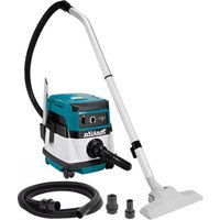
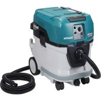
| Product Type | Cordless Vacuum Cleaner |
| Brand | Makita |
| Model | VC001GLZ |
| Tank Capacity (dust) | 8 L |
| Tank Capacity (water) | 6 L |
| Max air volume at hose end | 2,7 m³/min |
| Max air volume at turbine | 4,2 m³/min |
| Max vacuum pressure | 23 kPa |
| Rated voltage | DC 36 V - 40 V max |
| Net weight (with battery) | 8,1 - 11,2 kg |
| Dimensions (L x D x H) | 366 mm x 334 mm x 425 mm |
| Standard filter type | Cloth filter (dry and wet dust) |
| Protection rating | IPX4 |
| Compatible battery | BL4020, BL4025, BL4040, BL4040F, BL4050F, BL4080F |
| Compatible charger | DC40RA, DC40RB, DC40RC, DC40WA |
| Sound pressure level | 70 dB(A) or less |
| Vibration level | 2,5 m/s² or less |
| Suction functions | Dry and wet, automatic stop (float), power adjustment |
| Power supply | Dual battery (2 slots) or single battery |
| Integrated protections | Overload, overheating, deep discharge |
| Routine maintenance | Regular cleaning of cloth filter; washing HEPA filter with water |
| Optional accessories | HEPA filter, pre-filter, water filter, paper bag, polyethylene bag, MAKPAC adapter |
| Warranty and repairs | Authorized Makita service centers, original spare parts |
Frequently Asked Questions - VC001GLZ MAKITA
User questions about VC001GLZ MAKITA
0 question about this device. Answer the ones you know or ask your own.
Ask a new question about this device
Download the instructions for your Cordless vacuum in PDF format for free! Find your manual VC001GLZ - MAKITA and take your electronic device back in hand. On this page are published all the documents necessary for the use of your device. VC001GLZ by MAKITA.
USER MANUAL VC001GLZ MAKITA
- This machine is not intended for use by persons including children with reduced physical, sensory or mental capabilities, or lack of experience and knowledge.
- Children should be supervised to ensure that they do not play with the cleaner.
- See the chapter "SPECIFICATIONS" for the type reference of the battery.
- See the section "Installing or removing battery cartridge" for how to remove or install the battery.
- When disposing the battery cartridge, remove it from the tool and dispose of it in a safe place. Follow your local regulations relating to disposal of battery.
- If the tool is not used for a long period of time, the battery must be removed from the tool.
- Do not short the battery cartridge.
- See the chapter "MAINTENANCE" for the appropriate details of precautions during user maintenance.
SPECIFICATIONS
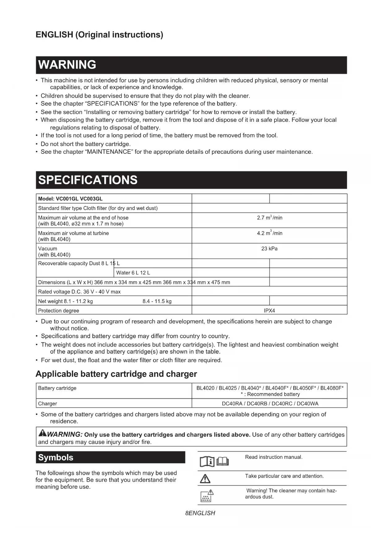
| Model: VC001GL VC003GL | |||
| Standard filter type Cloth filter (for dry and wet dust) | |||
| Maximum air volume at the end of hose(with BL4040,ø32 mm x 1.7 m hose) | 2.7 m³/min | ||
| Maximum air volume at turbine(with BL4040) | 4.2 m³/min | ||
| Vacuum(with BL4040) | 23 kPa | ||
| Recoverable capacity Dust 8 L 15 L | |||
| Dimensions (L x W x H) 366 mm x 334 mm x 425 mm 366 mm x 334 mm x 475 mm | |||
| Rated voltage D.C. 36 V - 40 V max | |||
| Net weight 8.1 - 11.2 kg | 8.4 - 11.5 kg | ||
| Protection degree | IPX4 | ||
- Due to our continuing program of research and development, the specifications herein are subject to change without notice.
- Specifications and battery cartridge may differ from country to country.
- The weight does not include accessories but battery cartridge(s). The lightest and heaviest combination weight of the appliance and battery cartridge(s) are shown in the table.
- For wet dust, the float and the water filter or cloth filter are required.
Applicable battery cartridge and charger
| Battery cartridge | BL4020 / BL4025 / BL4040* / BL4040F* / BL4050F* / BL4080F* : Recommended battery |
| Charger | DC40RA / DC40RB / DC40RC / DC40WA |
- Some of the battery cartridges and chargers listed above may not be available depending on your region of residence.

WARNING: Only use the battery cartridges and chargers listed above. Use of any other battery cartridges and chargers may cause injury and/or fire.
Symbols
The followings show the symbols which may be used for the equipment. Be sure that you understand their meaning before use.


Read instruction manual.

Take particular care and attention.

Warning! The cleaner may contain hazardous dust.
| Never stand on the cleaner. | |
| Dust class L (light). The cleaners are capable of picking up dust class L. Follow your country's regulations relating to dusts and to occupational health and safety. | |
| NI-MH Li-ion | Only for EU countries Due to the presence of hazardous components in the equipment, waste electrical and electronic equipment, accumulators and batteries may have a negative impact on the environment and human health. Do not dispose of electrical and electronic appliances or batteries with household waste! In accordance with the European Directive on waste electrical and electronic equipment and on accumulators and batteries and waste accumulators and batteries, as well as their adaptation to national law, waste electrical equipment, batteries and accumulators should be stored separately and delivered to a separate collection point for municipal waste, operating in accordance with the regulations on environmental protection. This is indicated by the symbol of the crossed-out wheeled bin placed on the equipment. |
Intended use
The appliance is intended for collecting both wet and dry dust. The appliance is suitable for commercial use, for example in hotels, schools, hospitals, factories, shops, offices and rental businesses.
Noise
The typical A-weighted noise level determined according to EN60335-2-69:
Model VC001GL
The noise level under working may exceed 80 dB (A).
NOTE: The declared noise emission value(s) has been measured in accordance with a standard test method and may be used for comparing one tool with another.
NOTE: The declared noise emission value(s) may also be used in a preliminary assessment of exposure.
WARNING: Wear ear protection.
WARNING: The noise emission during actual use of the power tool can differ from the declared value(s) depending on the ways in which the tool is used especially what kind of workpiece is processed.
WARNING: Be sure to identify safety measures to protect the operator that are based on an estimation of exposure in the actual conditions of use (taking account of all parts of the operating cycle such as the times when the tool is switched off and when it is running idle in addition to the trigger time).
Vibration
The vibration total value (tri-axial vector sum) determined according to EN60335-2-69:
Model VC001GL
Vibration emission (a_h,M) .. 2.5m / s^2 or less
Uncertainty (K): 1.5m / s^2
Model VC003GL
Vibration emission (a_h,M) .. 2.5m / s^2 or less
Uncertainty (K): 1.5m / s^2
NOTE: The declared vibration total value(s) has been measured in accordance with a standard test method and may be used for comparing one tool with another.
NOTE: The declared vibration total value(s) may also be used in a preliminary assessment of exposure.
WARNING: The vibration emission during actual use of the power tool can differ from the declared value(s) depending on the ways in which the tool is used especially what kind of workpiece is processed.
WARNING: Be sure to identify safety measures to protect the operator that are based on an estimation of exposure in the actual conditions of use (taking account of all parts of the operating cycle such as the times when the tool is switched off and when it is running idle in addition to the trigger time).
Declarations of Conformity
For European countries only
The Declarations of conformity are included in Annex A to this instruction manual.
SAFETYWARNINGS
Cordless vacuum cleaner safety warnings
WARNING:IMPORTANT!READ CAREFULLY all safety warnings and all instructions BEFORE USE. Failure to follow the warnings and instructions may result in electric shock, fire and/or serious injury.
- Before use, make sure that this cleaner must be used by people who have been adequately instructed on the use of this cleaner.
- Before use, operators shall be provided with information, instruction and training for the use of the machine and the substances for which it is to be used, including the safe method of removal and disposal of the material collected.
- If foam/liquid comes out, switch off immediately.
- Clean the water level limiting device regularly and examine it for signs of damage.
- Always make sure that filters are correctly installed before use. Do not use the cleaner without filters in place. Replace a damaged filter immediately. It is recommended to have some spares as filters are consumable items.
- AVOID UNINTENTIONAL STARTING. Be sure switch is OFF when installing battery(ies).
- Do not attempt to pick up flammable materials, fireworks, lighted cigarettes, hot ashes, hot metal chips, and sharp materials such as razors, needles, broken glass or the like.
- NEVER USE THE CLEANER IN THE VICINITY OF GASOLINE, GAS, PAINT, ADHESIVES OR OTHER HIGHLY EXPLOSIVE SUBSTANCES. The switch emits sparks when turned ON and OFF. And so does the motor commutator during operation. A dangerous explosion may result.
- Never vacuum up toxic, carcinogenic, combustible or other hazardous materials such as asbestos, arsenic, barium, beryllium, lead, pesticides, or other health endangering materials.
- Always place the cleaner on a horizontal flat surface to prevent it from falling or moving unintentionally.
- Never use the cleaner outdoors in the rain.
- For Finland, this machine is not to be used outdoors at low temperature.
- Do not use close to heat sources (stoves, etc.).
- If the exhaust air is returned to the room, it is necessary to provide for an adequate air change rate in the room. Reference to National regulations is necessary.
- Do not block suction inlet/outlet/cooling vents. These vents permit cooling of the motor. Blockage should be carefully avoided otherwise the motor will burn out due to a lack of ventilation.
- Keep proper footing and balance at all times.
- Do not fold, tug or step on the hose.
- Stop the cleaner immediately if you notice poor performance or anything abnormal during operation.
- REMOVE THE BATTERY(IES). When not in use, before servicing, and when changing accessories.
- Clean and service the cleaner immediately after each use to keep it in tiptop operating condition.
- MAINTAIN THE CLEANER WITH CARE. Keep
the cleaner clean for better and safer performance. Follow instructions for changing accessories. Keep handles dry, clean, and free from oil and grease.
22. CHECK DAMAGED PARTS. Before further use of the cleaner, a guard or other part that is damaged should be carefully checked to determine that it will operate properly and perform its intended function. Check for alignment of moving parts, binding of moving parts, breakage of parts, mounting, and any other conditions that may affect its operation. A guard or other part that is damaged should be properly repaired or replaced by an authorized service center unless otherwise indicated elsewhere in this instruction manual. Have defective switches replaced by authorized service center. Don't use the cleaner if switch does not turn it on and off.
23. For user servicing, the machine shall be dismantled, cleaned and serviced, as far as is reasonably practicable, without causing risk to the maintenance staff and others.
24. The machine should be technically inspected by the manufacturer, or an instructed person, at least annually, consisting of, for example, inspection of filters for damage, air tightness of the machine and proper function of the control mechanism.
25. When carrying out service or repair operations, all contaminated items which cannot be satisfactorily cleaned are to be disposed of; such items shall be disposed of in impervious bags in accordance with any current regulation for the disposal of such waste.
26. REPLACEMENT PARTS. When servicing, use only identical replacement parts.
27. When not in use, always store the cleaner indoors.
28. Wet filters and the interior part of the liquid container shall be dried before storage.
29. Be kind to your cleaner. Rough handling can cause breakage of even the most sturdily built cleaner.
30. Do not attempt to clean the exterior or interior with benzine, thinner or cleaning chemicals. Cracks and discoloration may be caused.
31. Do not use cleaner in an enclosed space where flammable, explosive or toxic vapors are given off by oil-based paint, paint-thinner, gasoline, some mothproofing substances, etc., or in areas where flammable dust is present.
32. Do not operate the cleaner or any tool while under the influence of drugs or alcohol.
33. As a basic rule of safety, use safety goggles or safety glasses with side shields.
34. Use a dust mask in dusty work conditions.
35. This machine is not intended for use by persons including children with reduced physical, sensory or mental capabilities, or lack of experience and knowledge.
36. Children should be supervised to ensure that they do not play with the cleaner.
37. Never handle battery(ies) and cleaner with wet
hands.
- Use extreme caution when cleaning on stairs.
- Do not use the cleaner as a stool or work bench. The machine may fall down and may result in personal injury.
Battery tool use and care
- Recharge only with the charger specified by the manufacturer. A charger that is suitable for one type of battery pack may create a risk of fire when used with another battery pack.
- Use power tools only with specifically designated battery packs. Use of any other battery packs may create a risk of injury and fire.
- When battery pack is not in use, keep it away from other metal objects, like paper clips, coins, keys, nails, screws or other small metal objects, that can make a connection from one terminal to another. Shorting the battery terminals together may cause burns or a fire.
- Under abusive conditions, liquid may be ejected from the battery; avoid contact. If contact accidentally occurs, flush with water. If liquid contacts eyes, additionally seek medical help. Liquid ejected from the battery may cause irritation or burns.
- Do not use a battery pack or tool that is damaged or modified. Damaged or modified batteries may exhibit unpredictable behaviour resulting in fire, explosion or risk of injury.
- Do not expose a battery pack or tool to fire or excessive temperature. Exposure to fire or temperature above 130^ may cause explosion.
- Follow all charging instructions and do not charge the battery pack or tool outside the temperature range specified in the instructions. Charging improperly or at temperatures outside the specified range may damage the battery and increase the risk of fire.
SAVE THESE INSTRUCTIONS.
WARNING: DO NOT let comfort or familiarity with product (gained from repeated use) replace strict adherence to safety rules for the subject product. MISUSE or failure to follow the safety rules stated in this instruction manual may cause serious personal injury.
Important safety instructions for battery cartridge
- Before using battery cartridge, read all instructions and cautionary markings on (1) battery charger, (2) battery, and (3) product using battery.
- Do not disassemble or tamper with the battery cartridge. It may result in a fire, excessive heat, or explosion.
- If operating time has become excessively shorter, stop operating immediately. It may result in a risk of overheating, possible burns and even an explosion.
- If electrolyte gets into your eyes, rinse them out with clear water and seek medical attention
right away. It may result in loss of your eyesight.
- Do not short the battery cartridge:
(1) Do not touch the terminals with any conductive material.
(2) Avoid storing battery cartridge in a container with other metal objects such as nails, coins, etc.
(3) Do not expose battery cartridge to water or rain.
A battery short can cause a large current flow, overheating, possible burns and even a breakdown.
- Do not store and use the tool and battery cartridge in locations where the temperature may reach or exceed 50^ (122°F).
- Do not incinerate the battery cartridge even if it is severely damaged or is completely worn out. The battery cartridge can explode in a fire.
-
Do not nail, cut, crush, throw, drop the battery cartridge, or hit against a hard object to the battery cartridge. Such conduct may result in a fire, excessive heat, or explosion.
-
Do not use a damaged battery.
-
The contained lithium-ion batteries are subject to the Dangerous Goods Legislation requirements.
For commercial transports e.g. by third parties, forwarding agents, special requirement on packaging and labeling must be observed. For preparation of the item being shipped, consulting an expert for hazardous material is required. Please also observe possibly more detailed national regulations. Tape or mask off open contacts and pack up the battery in such a manner that it cannot move around in the packaging.
- When disposing the battery cartridge, remove it from the tool and dispose of it in a safe place. Follow your local regulations relating to disposal of battery.
- Use the batteries only with the products specified by Makita. Installing the batteries to non-compliant products may result in a fire, excessive heat, explosion, or leak of electrolyte.
- If the tool is not used for a long period of time, the battery must be removed from the tool.
- During and after use, the battery cartridge may take on heat which can cause burns or low temperature burns. Pay attention to the handling of hot battery cartridges.
- Do not touch the terminal of the tool immediately after use as it may get hot enough to cause burns.
- Do not allow chips, dust, or soil stuck into the terminals, holes, and grooves of the battery cartridge. It may cause heating, catching fire, burst and malfunction of the tool or battery cartridge, resulting in burns or personal injury.
-
Unless the tool supports the use near high-voltage electrical power lines, do not use the battery cartridge near high-voltage electrical power lines. It may result in a malfunction or breakdown of the tool or battery cartridge.
-
Keep the battery away from children.
SAVE THESE INSTRUCTIONS.
CAUTION: Only use genuine Makita batteries. Use of non-genuine Makita batteries, or batteries that have been altered, may result in the battery bursting causing fires, personal injury and damage. It will also void the Makita warranty for the Makita tool and charger.
Tips for maintaining maximum battery life
- Charge the battery cartridge before completely discharged. Always stop tool operation and charge the battery cartridge when you notice less tool power.
- Never recharge a fully charged battery cartridge. Overcharging shortens the battery service life.
- Charge the battery cartridge with room temperature at 10^ - 40^ (50°F - 104°F). Let a hot battery cartridge cool down before charging it.
- When not using the battery cartridge, remove it from the tool or the charger.
- Charge the battery cartridge if you do not use it for a long period (more than six months).
PARTS DESCRIPTION
Fig.1: 1. Head unit 2. Float 3. Float cage 4. Cloth filter 5. Tank
FUNCTIONAL DESCRIPTION
CAUTION: Always be sure that the appliance is switched off and the battery cartridges are removed before adjusting or checking function on the appliance.
Installing or removing battery cartridge
CAUTION: Always switch off the appliance before installing or removing battery cartridges.
CAUTION: Hold the cleaner and battery cartridges firmly when installing or removing battery cartridges. Failure to do so may cause them to slip off your hands, resulting in damage to the cleaner and battery cartridges or personal injury.
CAUTION: Be careful not to pinch your fingers when opening or closing the battery cover. Failure to do so may cause personal injury.
The cleaner has double battery slots. With two identical batteries in parallel, you can extend your running time
in one or more uses without having to stop to recharge batteries. The cleaner also works with a single battery, so you can choose with either double batteries or single battery according to your needs.
Fig.2: 1.Left battery slot 2. Right battery slot
With double batteries
Continuous drive with two batteries allows longer runtime and more efficient cleaning. When the first battery is becoming empty, the cleaner automatically switches a power source, so it continues working with the second battery.
NOTE: The left battery slot (when facing the front of the cleaner) has priority over the right battery slot. The right battery slot will only be identified as a power source, either when no battery is installed in the left battery slot or the battery in the left battery slot becomes empty.
NOTE: You can remove the battery from the left battery slot and recharge it after the cleaner has switched its power source from the left battery slot to the right without ceasing operation. To give priority back to the left battery slot after installing a recharged battery, restart the cleaner.
With a single battery
Only one battery is required as a power source in either the left or right battery slot. The cleaner automatically determines which battery slot is available according to operating conditions.
Installation and uninstallation
To install battery cartridges, release the lock first, and open the battery cover. Then insert the battery cartridges.
Fig.3: 1. Lock 2. Battery cover
Align the tongues on the battery cartridges with the grooves in the battery housing and slip them into place. Insert them all the way until they lock in place with a little click.
Then lock the battery cover.
Fig.4: 1. Battery cartridge 2. Button
To remove the battery cartridges, slide them out of the battery housing while pressing and holding the buttons in front of the cartridges.
CAUTION: Always install the battery cartridge fully. If not, it may accidentally fall out of the appliance, causing injury to you or someone around you.
CAUTION: Do not install the battery cartridge forcibly. If the cartridge does not slide in easily, it is not being inserted correctly.
NOTE: When the cleaner switches the power source from the first battery to the second, it may require a temporary halt in operations, causing a slight loss of suction. Please note that it is not malfunction so the cleaner recovers and resumes operations immediately after the pause.
Indicating the remaining battery capacity
Press the check button on the battery cartridge to indicate the remaining battery capacity. The indicator lamps
light up for a few seconds.
Fig.5: 1. Indicator lamps 2. Check button
| Indicator lamps Remaining | capacity | ||
| Lighted Off | Blinking | ||
| 75% to 100% | |||
| 50% to 75% | |||
| 25% to 50% | |||
| 0% to 25% | |||
| Charge the battery. | |||
| The battery may have malfunctioned. | |||
NOTE: Depending on the conditions of use and the ambient temperature, the indication may differ slightly from the actual capacity.
NOTE: The first (far left) indicator lamp will blink when the battery protection system works.
Battery indicators on control panel
The remaining battery capacity can be read on the control panel at any time. Press the check button, and the left and right indicators will show the battery charge levels correspondingly.
Fig.6: 1. Battery indicators 2. Check button
Fig.7
| Battery indicator status Remaining | battery capacity | ||
| On Off | Blinking | ||
| 50% to 100% | |||
| 20% to 50% | |||
| 0% to 20% | |||
| Charge the battery | |||
| Battery not inserted | |||
NOTE: The battery indicators will also be activated when the cleaner starts functioning or switches its power source from one to another.
Appliance / battery protection system
The appliance is equipped with an appliance/battery protection system. This system automatically cuts off power to the motor to extend appliance and battery life. The appliance will automatically stop during operation if the appliance or battery is placed under one of the following conditions:
Overload protection
When the appliance/battery is operated in a manner that causes it to draw an abnormally high current, the appliance automatically stops. In this situation, turn the appliance off and stop the application that caused the appliance to become overloaded. Then turn the appliance on to restart.
Overheat protection

When the appliance is overheated, the appliance stops automatically, and both left and right battery indicators blink. In this situation, let the appliance cool down before turning the appliance on again.

When the battery is overheated, the appliance stops automatically, and one of the indicators for overheated battery blinks. In this situation, let the battery cool down before turning the appliance on again.
Overdischarge protection
When the battery capacity becomes low, the appliance stops automatically. If the appliance does not run along with the switch operation, remove the batteries from the appliance and recharge them.
Protectons against other causes
Protection system is also designed for other causes that could damage the appliance and allows the appliance to stop automatically. Take all the following steps to clear the causes, when the appliance has been brought to a temporary halt or stop in operation.
- Turn the appliance off, and then turn it on again to restart.
- Charge the battery(ies) or replace it/them with recharged battery(ies).
- Let the appliance and battery(ies) cool down.
If no improvement can be found by restoring protection system, then contact your local Makita Service Center.
Switch action
Turning cleaner on
- Turn the stand-by switch in the "I" (ON) position to
have the cleaner ready in stand-by mode.
- Press the power button.
To switch back to stand-by mode, press the power button again.
Turning cleaner off
Perform one of the following steps.
- Press the power button to set the cleaner back in stand-by mode, and then turn the stand-by switch in the "O" (OFF) position.
- Turn the stand-by switch in the "O" (OFF) position.
Adjusting suction power
The suction power can be adjusted according to your work needs.
- Turn the suction force adjusting knob to the left to reduce the suction power.
- Turn the suction force adjusting knob to the right to increase the suction power.
Fig.8: 1. Stand-by switch 2. Power button 3. Suction force adjusting knob
Auto-suction stop during wet suction operation
WARNING: Do not use for a long time while the float is at work. Using the cleaner with its float at work for a long time can cause overheat, resulting in the cleaner deformation.
WARNING: Do not pick up foam or soapy liquid. It can cause foam to come out of air exit before the float works. Continuous use under such conditions may cause an electric shock and breakage of the cleaner.
The auto-suction stop feature works only while the cleaner is used with the float and float cage.
The cleaner has a float mechanism that prevents water from entering into the motor when picking up more than a certain amount of water. When the tank is full and the cleaner no longer picks up water, switch off the cleaner and empty the tank.
Locking and unlocking casters
Rear casters can be locked with stoppers to help the cleaner stand still.
Lower the stopper lever by hand to lock the caster, and raise it up to release.
Fig.9: 1. Caster 2. Stopper lever 3. Unlocked position 4. Locked position
NOTE: When moving the cleaner, make sure that the caster is unlocked. Moving the cleaner with the caster in a locked position may cause damage to the caster.
Carriage handle
CAUTION: Lift and carry the appliance with due care. Failing to do so may result in personal injury or damage to the appliance.
When carrying the cleaner, carry it by holding the handle on the head unit. The handle is retractable on the head unit when not in use.
Fig.10
ASSEMBLY
CAUTION: Always be sure that the appliance is switched off and the battery cartridges are removed before carrying out any work on the appliance.
CAUTION: Always wear dust mask during assembly or maintenance.
Installing powder filter (HEPA) and prefilter (for dry dust)
Optional accessory
CAUTION: Never pick up water or other liquids or wet dusts when using the powder filter. Picking up such things may cause the powder filter breakage.
To use powder filter:
- Loosen the screws securing the float cage, and then remove the screws, float cage and float from the head unit.
Fig.11: 1. Screw 2. Float cage 3. Float 4. Head unit
2. Remove the cloth filter out of the tank.
Fig.12: 1. Cloth filter 2. Tank
3. Place the prefilter into the tank aligning the mounting position markings on the prefilter and tank.
4. Set the damper into the prefilter, and then place the powder filter over the damper aligning the mounting position markings on the powder filter and prefilter.
5. Mount the head unit over the tank and secure them with the locking latches.
Fig.13: 1. Head unit 2. Powder filter (HEPA) 3. Damper 4. Prefilter 5. Tank 6. Mounting position marking
NOTICE: Before using the powder filter, make sure that prefilter and damper are used together. It is not allowed to install powder filter alone.
Installing water filter
Optional accessory
NOTICE: Never pick up water or wet dust without the float and the cloth filter or the water filter.
NOTICE: For picking up wet dust, make sure that the float cage and the float are installed on the cleaner.
NOTICE: When installing the water filter on the tank, set it tight at the opening of the tank so that the hook of the water filter engages the tank opening firmly and there is no space between the water filter and the tank.
To pick up water or wet dust only, the water filter is more suitable than the cloth filter.
When installing the water filter, align its mounting position marking with the one on the tank.
Fig.14: 1. Water filter 2. Tank 3. Mounting position
NOTE: It is recommended using water filter when picking up large amount of water repeatedly. Otherwise vacuum ability may be reduced in case of cloth filter.
Installing paper pack
Optional accessory
WARNING: Before using a paper pack, make sure that the cloth filter or prefilter is used together. Failure to use the cloth filter / prefilter together may cause unusual noise and heat, resulting in a fire.
NOTICE: Never pick up water or other liquids or wet dusts when using a paper pack. Picking up such things may cause the paper pack breakage.
NOTICE: When using the cloth filter, make sure that the float and the float cage are attached on the head unit.
NOTICE: When using the prefilter, make sure that the powder filter and the damper are used together.
- Unfold a paper pack.
- Align the paper pack opening with the dust intake of the tank.
- Install the paper pack into the tank with its cardboard opening hooked on the paper pack holder.
Fig.15: 1. Paper pack 2. Cardboard opening 3. Paper pack holder 4. Dust intake
Installing polyethylene bag
With a polyethylene bag installed in the tank, you can easily empty the tank without letting your hands dirty.
Lay a polyethylene bag over the tank, and slip one side of the top edge of the bag at its open end in between the holder plate and the front wall of the tank.
▶ Fig.16: 1. Holder plate 2. Front wall of tank 3. Polyethylene bag
Spread the other top edges of the bag outwards over the top rims of the tank. Place the cloth filter or prefilter over the polyethylene bag to fasten the opening of the bag securely.
Fig.17: 1. Cloth filter / prefilter
NOTE: A polyethylene bag available on the market can be used. 0.04mm or thicker one is recommended.
NOTE: Too much dust will tear the bag easily, so do not collect the dust more than the half of the bag capacity.
Emptying tank with polyethylene bag
WARNING: Always make sure that the cleaner is switched off and the battery cartridges are removed before emptying the tank. Failure to do so may cause an electric shock and serious personal injury.
NOTICE: Do not apply a great impact on the float cage and tank. Applying a great impact may cause deformation and damage to the parts.
NOTICE: Empty the tank at least once a day although this depends on picked-up dust volume in the tank. Or, the suction force will weaken and the motor may be broken.
NOTICE: Do not grab the hooks or latches when emptying the tank. Grabbing the hooks or latches may cause them to break.
Release the locking latches and lift the head unit up off the tank.
Shake off dust from the cloth filter or prefilter before lifting the filter away from the tank.
Then remove the polyethylene bag out of the tank, closing the opening of the bag by hand.
Fig.18: 1. Polyethylene bag 2. Tank
NOTE: Take the polyethylene bag out of the tank carefully to avoid it from being scratched and torn by the edges inside the tank.
NOTE: Empty the polyethylene bag before it becomes full. Too much dust in the tank may cause the polyethylene bag to be torn.
Installing multi hook
Use the multi hook to hold a hose, accessories and attachments not in use in place, and you can quickly take them out according to your preferences.
Fig.19
Place the multi hook over the mounting base at the rear of the cleaner, setting the rails on the multi hook along the grooves on the mounting base.
Fig.20: 1. Multi hook 2. Mounting base
Installing MAKPAC adapter
Optional accessory
Connectable and stackable MAKPAC storage cases can be installed on top of the cleaner with an optional adapter. The cases are available in many sizes and styles to suit your preferences.
Place the mounting base hook over the handle of the cleaner with its mounting surface facing upwards when the handle is folded into the closed position.
Fig.21: 1. Mounting base hook 2. Mounting surface 3. Handle
Mount the MAKPAC adapter onto the mounting base hook, and secure them together with four screws provided.
Fig.22: 1. MAKPAC adapter 2. Mounting base hook
3. Screw
Lift the push bar up and tighten the knob to prepare installing the MAKPAC cases onto the cleaner.
Fig.23: 1. Push bar 2. Knob
NOTE: For details on installing the MAKPAC cases, refer to the instructions provided with the MAKPAC adapter and cases.
Installing hose
NOTICE: Never force the hose for bending or stamp it. Never move the cleaner by pulling the hose. Forcing, stamping and pulling the hose may cause a breakage or deformation of the hose.
NOTICE: When picking up large wastes such as planer carvings, concrete dusts or similar other than small wastes, use the 38mm inner diameter hose (optional accessory). Using the 28mm inner diameter hose (optional accessory) may cause a hose stuffing and damage.
Connection to cleaner
Insert the hose end to the dust intake (hose inlet) of the cleaner, then turn it clockwise until it locks in place.
Fig.24: 1.Hose 2.Dust intake (hose inlet)
Connections with your work tools (Country specific)
By connecting the vacuum cleaner to any available work tools compatible with the cleaner, it works as a dust extractor for your power tools.
To connect a tool to the cleaner, the dedicated hose and/or additional parts are required. Depending on your cleaner model, you need to replace the hose and/or prepare additional parts.
Select one of the front cuffs or joints (optional accessories) as most suitable for your tool model. Place the cuffs or joint, as necessary, between the front end of the cleaner hose and a dust extraction port of your tool.
Fig.25: 1. Front cuffs or joint 2. Cleaner hose
- Power tool 4. Vacuum cleaner
Installing or removing cleaner attachments
CAUTION: After installing an attachment, check if it is securely installed. If the attachment is installed imperfectly, it may come off and cause personal injury.
Attaching bent pipe assembly
Optional accessory
NOTE: You don't need to perform this procedure if your model comes with the bent pipe assembly attached to the hose.
The bent pipe assembly is used for connecting the extension wand or nozzle for vacuum cleaning to this product.
If you want to use this product as the vacuum cleaner, attach the bent pipe assembly to the hose.
For the screw-in type bent pipe assembly
To attach, unscrew the front cuff from the hose and fasten the sleeve of bent pipe assembly onto the hose. To remove, loosen the sleeve of bent pipe assembly from the hose.
Fig.26: 1.Hose 2.Bent pipe assembly 3.Sleeve
For the snap-on type bent pipe assembly
To attach, insert the hose end into the bent pipe assembly. Make sure that the tabs on the hose end snap into the holes on the bent pipe assembly.
To remove, pull the bent pipe assembly while pressing both of the tabs on the hose end.
Fig.27: 1.Hose end 2.Tab 3.Hole 4.Bent pipe assembly
Attachments without lock function
Optional accessory
Insert an attachment into the suction inlet of the cleaner by pushing and hand screwing it in place.
Hand twist and pull the attachment apart from the suction inlet after use.
Fig.28
Attachments with lock function
Optional accessory
NOTICE: When installing the attachment with lock function, be sure to align the release button with the hook on the attachment. If they are not aligned, the attachment will not be locked and may come off from the cleaner.
Insert an attachment into the suction inlet of the cleaner by pushing them together with a click. To remove the attachment, pull it off while pushing the release button.
Fig.29: 1. Suction inlet with lock function 2. Release button 3. Attachment with lock function
NOTE: An attachment with lock function can only be installed in the suction inlet with lock function.
Fig.30: 1. Attachment with lock function 2. Suction inlet with lock function 3. Suction inlet without lock function
Assembling nozzle and wand
Optional accessory
NOTE: The type of the nozzle and wand included in the product varies depending on countries. In some countries, the nozzle and wand are not included.
Twist and insert the nozzle to the extension wand.
Fig.31: 1. Extension wand 2. Flexible rubber nozzle
- Corner nozzle 4. T-shape nozzle
NOTE: By twisting the nozzle while inserting, the nozzle can be attached to the extension wand securely.
NOTE: For the model with 38mm hose and front cuff 38, attach the supplied nozzle to the aluminum bending pipe / aluminum straight pipe.
When using floor/carpet switching t-nozzle, you can change the mode depending on the place.
- Floor mode: suitable for a smooth place such as a hard floor
Carpet mode: suitable for a shaggy place such as a carpet or a rug
Fig.32: 1.Mode switching button 2.Floor mode 3.Carpet mode
Adjusting lengths of slide-type extension wand
Optional accessory
A slide-type extension wand can be combined for shorter and longer lengths. It allows to clean hard-to-reach areas and comfortable positioning options.
Pull in and out the slide pipe to change wand lengths while pressing and holding the slide button. Release the slide button to lock the slide pipe in your desired position.
▶ Fig.33: 1. Slide pipe 2. Slide button
MAINTENANCE
CAUTION: Always be sure that the appliance is switched off and the battery cartridges are removed before attempting to perform inspection or maintenance.
NOTICE: Never use gasoline, benzine, thinner, alcohol or the like. Discoloration, deformation or cracks may result.
To maintain product SAFETY and RELIABILITY, repairs, any other maintenance or adjustment should be performed by Makita Authorized or Factory Service Centers, always using Makita replacement parts.
Storage of accessories
Accessories and attachments not in use, such as nozzles and brushes, can be hooked and stored in the multi hook at the rear of the cleaner.
Fig.34: 1. Multi hook 2. Accessories and attachments not in use
Pipes (with an optional stopper installed) can be placed into the pipe holder when not using the cleaner for a short time.
Fig.35: 1. Stopper (optional accessory) 2. Pipe holder
A hose can be wrapped and stored around the housing or handle of the cleaner in large loops. Connect its both ends together to make loops and hook the loops onto the handle raised up. Alternatively, keep its root end installed in the hose inlet and hang the loops on the multi hook with the loose end tied up.
Fig.36
Fig.37
Cleaning of cloth filter
Clean out the cloth filter at regular intervals since clogged cloth filter may result in poor suction
performance.
Wipe and shake dust off the cloth filter by hand on occasions.
Fig.38:1.Cloth filter
Cleaning of powder filter (HEPA) and prefilter
Optional accessory
Clean out the powder filter, prefilter and damper at regular intervals since clogged filters and damper may result in poor suction performance.
Routinely wipe and shake dust off filters and damper by hand.
Occasionally wash the powder filter in water, rinse and dry thoroughly in the shade before use. Never wash filters in a washing machine.
Fig.39
NOTE: Do not rub or scratch the powder filter, the prefilter and the damper with hard objects such as a brush and a paddle.
NOTE: The filters wear out in course of time. It is recommended to have some spares for them.
OPTIONAL ACCESSORIES
CAUTION: These accessories or attachments are recommended for use with your Makita tool specified in this manual. The use of any other accessories or attachments might present a risk of injury to persons. Only use accessory or attachment for its stated purpose.
Some accessories may not be installed according to the combination of parts.
If you need any assistance for more details regarding these accessories, ask your local Makita Service Center.
Hose
- Front cuffs (22, 24, 38)
Straight pipe
- Extension wand
- Corner nozzle
- Round brush
- Powder filter, HEPA (for dry dust)
Damper
- Prefilter
Water filter
- Cloth filter
T-shape nozzle
- Bent pipe
Polyethylene bag
- Paper pack
- MAKPAC adapter
- Makita genuine battery and charger
NOTE: Some items in the list may be included in the tool package as standard accessories. They may differ from country to country.
AVENTISSEMENT
VEILIGHEIDSWAAR-SCHUWINGEN
Fig.38: 1. Doekfilter
OPTIONELE ACCESSOIRES
Móvo yia xwpe ts Eupwnns
Oi Anwosic Umuoppwoc Tepiaaavovtai oTo
IPOEIAOIOIHSEIEA∑ΦAΛEIA∑
PpOeIoToiInoEic aOgpaAeiaC yia Tn oopntn unxavn avappofoons
AIPOEIAOIOIHsE:HMANTIKOIABAEIPOZEKTIAoAESTIGPoeiOToInoeicVtNVAaAiaKaioAESTCOnyieSINPIN ANOTXPHH.Hn nponTswvTPOeIDOTOnoeWVKooyiw mOpEvaKaataAnEi OE nEktpoiAnxi,TPkayia/ka oBapopTaupatio.
- Pniv aTn Xpno, BepaiwOeite oTn n unxavn 0a xpnoiopoTne i aTc ato a OTOia exouv dooTei eTapkeic odnyiec yia tn xpnoaunns nuxavnc.
- Piv Tn xpion, OTOUC xeiipotc 0a dooouv
TAnpoopiec, oynies kai ekTiaEuaon yia tn
Xpion Tou mnxavnaTOCs kai twv ouoiw uTIC
OTIOEC 0x npoiuOInOe i, oupiIaIauvaO
Evnc Tns aospalouc e060ou apaipoean cai
Diaeocn Tou ulikou Tou ouAExOnke. - Av aphiocluypo, ohtote aedowc.
- Na kaθapiετε TAKIKA ηιαταη περιομου tns σταθμης ερού καιν την εξεταζετε για ενδείξεις ζημιας.
- Na navte navta ot ta piaItpa exouvtnoIeTnOwotaaipntxpnon.MnxpnoiIOIOIEtn oKoUTaXwpicTa piaItpa va Bpiokovtai Otn Theouc.AvtikataoTnotae aEswc eva pilpto Toue Exei UTOOTei Znmu. Suviotatai va exetepeikakvaalaktka ETEIDn ta piaItpa eivai avawioimaavikejeva.
- NA ANOΦEYETETHN AOEAHTH ENEPRONOHSH. Beaiωeite oti o diakottnε εivai KAEI2TO2 oTav too3eite Tnv(Tiε) μπatapia(εs).
- Mny ETIXEIPNOETe va OUAALESETE EUFAEKTA uIKA, TUPOTExVnmuata, avaumeva ToiYapa, KAUTEC OTAXTEC, ZOToA METALIAK OpaoumaT AaiXnpa AVTIKEIeVA 0TWC lupapKaia, BELoVEc, OTAoMuEv yuaI n TAPoioa AVTIKEIeVA.
- MH XPHESIMONIOEITE NOTE TH MHXANH KONTA ZE BENZINH, AEPIA, MNOTIA, KOANES H ANAE YYHAA EKPHKTIKEO YSIE. O 0 kottnc npayei OTIVnpec otav evepytoiei tai kai aTVEpyoioeitai. To idoi kai o eTatpoTtac potepkata ndiapkeia nC LEIToupyiac. MTOPEI VA TPOKUeI ETIKIVDuvN EkPnN.
- Mny avappoate TOTe Toikka, KAPKIVOyova, Kaouma n aaaa EtnIKivuva uika, otwcauiavto, apoeviko, bapio, npuAIO, oluBdo, EvTOPOKTovn aaaa uikauTou aTtEaovkivduvo yia tny uyia.
-
Na toTOnoTeEite TavTa Tn OkaUta Oe opizovia EtnieDn EtniPavEia, ia va aTopeuxTei nTTwoh n n metakivnoTns kata laOos.
-
Mn xpooiopoite troe tn unxavn oE eGwTe- piko xwpo stn bpoxn.
- Iα ηιλαδία, autο to μηχανημα δεν πρεπειν αχροσιμοτοιθει σε εξωτερικός χωρους σε χαμηλή θερμοκρασία.
- Mn xpnoiopoioite Kovtα oE Tnyec θερμοτηας (φουρονι, kτλ).
- Av o aépaç éaywync eTIOTpepei OTO dWmaTIO, Eivai aTapaiNTo va φpovTiOe TIA TOV eTAPKn puθu o aaaync Tou aepa OTO dWmuTIO. Eivai aTapaiNTo va avatpeEeTe OTouc eVkoUc kavovioouc.
- Mny aooetra aoivmuata eioobou avappoqnonc/foobou/psiugns.Autara ovoiyuata emipetiouv nvy uign tou potep.Oa pentei va atoepuxtheta pooeKTikato ppaigo, diaopotika to potep 0a kaei loyw eaaiwns aepioou.
- Na οTEKEOTE πáVTA σταθερα KAI IOOPPOTTημενα.
- Mn διπλωνετ, μυν τραβάτε και μυν πατάτε τον εύκαμτιτο σωλήσα.
- AiaKoYTE aEosG Tn aeitoupyia nns mXavns av npapntpnoTe AVtapkn ano0on n otioh-TOTE aovnIOTO kata n aeitoupyia.
- BRAFTHETN(TI) MNATAPIA(ES).OTAV v xpnoiopoioietai,piiv aTTo oepic kai otav aaacTe aegouap.
- Kaθαριοτε και εκτέλεότε σέρβις Οη μήχανή αμέσως Μετά πτο καθε χρόη γίαν διαπηρεῖται εἰρισθη λεΙΤΟΥΚΑ ΚΑΤΑΟΤΑθ.
- DIATHPEITE TH MHXANH ME NPOEXH. Na δiatnpéite Tn μnxavn kaθapn yia tvn kaλutepn kai aσφaλeσtepn anóðoyn. Na akolouθeite Tis odnyies ia tvn aaayn twv aεosouap. Na δiatnpéite Tc λβες στeyvες, kaθapeç, χωpiς λádi kai ypáso.
- NA EAEIXETE TA MEPH ME ZHMIA. NIV aTNO TNV TEPaIePw XpOg TnS uXavNc, 0a TpeTNI VA ELEyXeTE TPOeKTIKA TUxov TPOoTATEUTIKA EApTmuata n aAAA eApTmaue znMia yia va KaOpioTe av 0a LEIToupyoouv OoTa kai av 0a TpaYauToIOuouv Tnv TPOoPiOeV N LEIToupyia touc. ELeyTe Tnv EUOuypamion Tuv KIVOUeVW UEPW, Tnv ELEUeepn KIVOn Tuv KIVOUeVW UEPW, TO TUxov OTAOIO EApTmuTsw, TN OTEpewon KAI OTIOEODHNTOTE aAAe Sc UVhKeC Tou μTopei va EINPeaoov Tn LEIToupyia Tou epyaaleiou. Ev aTPOta- TEUTIKo n aALLO EApTmaue znMia 0a TpeTNI VA ETIOKEuaOtei nva AVTKATAOTae i OwotA OE ESOIOBDtnevo Kevtpo oepic EKToc av 0nawetai biaopetikc oTO napov EYxepidio Obnyiw. OI EAATTWMATIKOI BIAKOttnc PpeTNI VA AVTKAoiTavTA OE EGOIOBtnevo Kevtpo oepic. Mn xpoioTOIEITE n mXavn av 0 dIAKOttnc DEv Tnv EVePyOTIOEi KAI DEv Tnv aTVEpyoTOie.
- Tia Tc epyaoc epic aTo To xpntn, to uXavma mtoe va aToouvapmooynei, va Kaatopei kai va ouvtnpn0e, 0o eivai Euloya TpaKTIO, Xwpi v npoknKivobuvoc oTO TpoosNIKO ouvtnpns KAI Oe aaouc.
- To mnxavma 0a pentei va utoketai oTe xviik eithewponn anto tov kataokeuaotn,
n aTIO EVTEaIevo aToO, TouIaxioTov Etn-
oiWs, TepiauBavovTac, yia TapaBcivua, Tnv
ETIeWpOnT Twv qIATpwV ia ZnuiA, Tnv aePo-
oTeyavOTNa Tou mXavNuAtoc kai Tn Owotn
AEiToupyia Tou mXavIoou eEyxou.
- Otav dieyayayete epyaiec oepic n eTI- OKEunc, 6a ta paoluaeva stoixei aou dev mTropouv va kaapioTuov oe IKavotnointiko npTei va diatebouv. Auta ta oToixei TpETei va diatebouv meca aiaepa- OTEc oakouaes uqwva e OTIOVbntote IOXovota kavovio yia tn diaheon tetoiw v anoBantw.
- ANTAAAKTIKA. KaTaTo eepBic, va XpnoiopoTIOIEITE mOvo yvnoia avtaaakTikca.
- NA ANOOHKEYETEHMHXANH OTAN DEN TH XPHSIMOIOIEITE. Otau xpnoiotoi- etai, n uynxavn 0a npetie va aTOnkEeTaI e EOWTEPIKO Xwpo.
- Ta uypa φiAtpa kai To eowtepiKo hépos Tou Doxeiou uypou πpentei va oTeyvwosouv Tpv Tnv aTOnkkeuon.
- Na TPOOExETe Tn mXavn. O oKLnpoC xEipi- MTOpei va TpOKaLoei To OTAOIO aKoN KAI TNS TIO KALOkataoKEuaoEvns mXavns.
- Mny ETIeipnoTe v a KaOapioTe To EwTepiKo nTO EOWTEPIKO eBVzivn, VepTIN KAtapiOTiKcXnuiKc ouoiC. MTopei va TpokAnouv Pwyue Kai aTOxPwpatioos
- Mn xpnoiomoiite Tn mnxavn o KAEIOTOxwpo OTov oTIO aTNEAUeOEPWVOVTa EUpAekToI, EKPNTIKOI n ToSIKOi aTmoi aTIOYIEc ME BaoN to Aadi, VepTI, BeVzivn, epiKec ouieC kata TnC OKouPiAc, KTA., n OE TEPIOXc OTou UTRApXei EUpAekTNoVn.
- Mn xpoiooioe ie auto to epyaeeio n otoio- 0nTote aAoo epyaeeio uTo tv Etnpeia vapKwTikwovouiownAkoA.
- Ως βαοικός κανόνας ασφαλείας, να χρησιμο-ποιείτη γυαλία σφαλείας ἡ γυαλία με πλαῖνα προστateutικά.
- Na xpoioiopoieite paoka kata TnC oKovns Oe ouvkec me tonnnkovn.
- To mnxavma auto dev npoipzeta i yia xpon an aToaoua, ouupeiaauabavouevwv twv taIdeltav, e uoiuecs oomegaatikc, aoentnpiec n diavontikc ikavotntec, n aTo aToa pou dev exouv Teipa kai yywoeis.
- Ta traiai a trpTei va eTInnpouvtai va v EgaaiaioTei oTI dev taizouv ME tn unxavn.
- Mn xεi piεoTe TnT (Tic) μπatapia (εc) kai Tn ΣkouTTa με βρεγμéva xépiα.
- Na TPOOEXE Idaitepa otav KaθapiεTe σkaIOTATIA.
- Mn xpnoiomoiéite tn unxav n ia okapto n triyko epyaosiaç. H unxavn okoouta mtopei va TEOI KAI VA TTpokaloei TTPOOWTIKO Tpaumatouo.