UAT505EUR - Underground network detector Beha-Amprobe - Free user manual and instructions
Find the device manual for free UAT505EUR Beha-Amprobe in PDF.
User questions about UAT505EUR Beha-Amprobe
0 question about this device. Answer the ones you know or ask your own.
Ask a new question about this device
Download the instructions for your Underground network detector in PDF format for free! Find your manual UAT505EUR - Beha-Amprobe and take your electronic device back in hand. On this page are published all the documents necessary for the use of your device. UAT505EUR by Beha-Amprobe.
USER MANUAL UAT505EUR Beha-Amprobe
natural_image
Technical line drawing of two mechanical devices with no visible text or symbolsUAT-505-EUR
Underground
Utility Locator
User Manual
ENNGERITASPA
FREDUTPOLSWE
FINPORNORDAN
UAT-505-EUR Underground Utility Locator
User Manual
Limited Warranty and Limitation of Liability
Your Beha-Amprobe product will be free from defects in material and workmanship for two years from the date of purchase unless local laws require otherwise. This warranty does not cover fuses, disposable batteries or damage from accident, neglect, misuse, alteration, contamination, or abnormal conditions of operation or handling. Resellers are not authorized to extend any other warranty on the behalf of Beha-Amprobe. To obtain service during the warranty period, return the product with proof of purchase to an authorized Beha-Amprobe Service Center or to an Beha-Amprobe dealer or distributor. See Repair Section for details. THIS WARRANTY IS YOUR ONLY REMEDY. ALL OTHER WARRANTIES - WHETHER EXPRESS, IMPLIED OR STATUTORY - INCLUDING IMPLIED WARRANTIES OF FITNESS FOR A PARTICULAR PURPOSE OR MERCHANTABILITY, ARE HEREBY DISCLAIMED. MANUFACTURER SHALL NOT BE LIABLE FOR ANY SPECIAL, INDIRECT, INCIDENTAL OR CONSEQUENTIAL DAMAGES OR LOSSES, ARISING FROM ANY CAUSE OR THEORY. Since some states or countries do not allow the exclusion or limitation of an implied warranty or of incidental or consequential damages, this limitation of liability may not apply to you.
Repair
All Beha-Amprobe tools returned for warranty or non-warranty repair or for calibration should be accompanied by the following: your name, company's name, address, telephone number, and proof of purchase. Additionally, please include a brief description of the problem or the service requested and include the test leads with the meter. Non-warranty repair or replacement charges should be remitted in the form of a check, a money order, credit card with expiration date, or a purchase order made payable to Beha-Amprobe.
In-warranty Repairs and Replacement – All Countries
Please read the warranty statement and check your battery before requesting repair. During the warranty period, any defective test tool can be returned to your Beha-Amprobe distributor for an exchange for the same or like product. Please check the "Where to Buy" section on beha-amprobe.com for a list of distributors near you. Additionally, in the United States and Canada, in-warranty repair and replacement units can also be sent to an Amprobe Service Center (see address below).
Non-warranty Repairs and Replacement – Europe
European non-warranty units can be replaced by your Beha-Amprobe distributor for a nominal charge. Please check the "Where to Buy" section on beha-amprobe.com for a list of distributors near you.
Beha-Amprobe
Division and reg. trademark of Fluke Corp. (USA)
Germany* United Kingdom The Netherlands - Headquarters**
In den Engematten 14 52 Hurricane Way BIC 1
79286 Glottertal Norwich, Norfolk 5657 BX Eindhoven
Germany NR6 6JB United Kingdom The Netherlands
Phone: +49 (0) 7684 8009 - 0 Phone: +44 (0) 1603 25 6662 Phone: +31 (0) 40 267 51 00
beha-amprobe.de
beha-amprobe.com
beha-amprobe.com
*(Correspondence only – no repair or replacement available from this address. European customers please contact your distributor.)
**single contact address in EEA Fluke Europe BV
CONTENTS
- PRECAUTIONS AND SAFETY MEASURES......2
- KIT COMPONENTS ....4
2.1 Your shipping box includes....4
2.2 UAT-600-RE Receiver Controls and Display....5
2.3 UAT-600-RE Receiver Alerts 8
2.4 UAT-500-TE Transmitter Controls and Display 9
2.5 SC-600-EUR Signal Clamp 9
- MAIN APPLICATIONS ....10
3.1 General Tracing Techniques for All Applications 10
3.2 Power Mode 50/60 Hz
- Passive Location of Energized Cables and Power Lines....11
3.3 Radio Mode – Passive Location of Utilities 12
3.4 Induction Mode – Locating Utilities 12
3.5 Direct Test Leads Connection Mode
- Tracing an Individual Pipe or Cable ....14
3.6 Signal Clamp Accessory – Tracing an Individual Pipe or Cable 17
- SPECIAL APPLICATIONS ....18
4.1 Locating Non-Metallic Pipes and Sewer Lines....18
4.2 Taking Depth Measurements....18
4.3 Advanced Locating Techniques – Two Person Swap....18
- MAINTENANCE ....20
5.1 Battery Replacement 20
- SPECIFICATIONS ......21
1. PRECAUTIONS AND SAFETY MEASURES
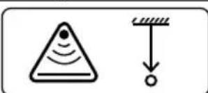
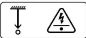
SYMBOLS
| (KHDZ) | Caution! Refer to the explanation in this manual. |
| (7KK5) | WARNING HAZARDOUS VOLTAGE. Risk of electric shock. |
| (2732) | Consult user documentation. |
| (46XT) | The equipment is protected by double insulation or reinforced insulation. |
| (04TG) | For De-energized system only. |
| (167A) | Earth (Ground). |
| (47CZ) | Battery. |
| (H7GB) | Certified by CSA Group to North American safety standards. |
| (H4ZG) | Complies with European Directives. |
| (WCHK) | Conforms to relevant South Korean EMC Standards. |
| (CAS3) | Conforms to relevant Australian standards. |
| (TX3S) | This product complies with the WEEE Directive marking requirements. The affixed label indicates that you must not discard this electrical/electronic product in domestic household waste. Product Category: With reference to the equipment types in the WEEE Directive Annex I, this product is classed as category 9 “Monitoring and Control Instrumentation” product. Do not dispose of this product as unsorted municipal waste. |
SAFETY INFORMATION
The product complies with:
- UL/IEC 61010-1, CAN/CSA C22.2 No. 61010-1, Pollution Degree 2, UAT-600-RE receiver: Measurement Category CAT IV 600 V MAX
- IEC 61010-2-033
• IEC 61010-031 (test leads)
• EMC IEC 61326-1
MEASUREMENT CATEGORY IV (CAT IV) is for equipment installed at or near the origin of the electrical supply to a building, between the building entrance and the main distribution board. Such equipment may include electricity tariff meters and primary overcurrent protection devices.
CENELEC Directives
The instrument conforms to CENELEC Low-voltage directive 2014/35/EU and Electromagnetic compatibility directive 2014/30/EU.
⚠️⚠️Warnings: Read Before Using
To avoid the possibility of electric shock or personal injury:
- Use the Product only as specified in this manual or the protection provided by the instrument may be compromised.
- Avoid working alone so assistance can be rendered.
- Test on a known signal source within the rated voltage range of the Product both before and after use to ensure the Product is in good working conditions.
- Do not use the Product around explosive gas, vapor, or in damp or wet environments that exceed IP54 rating per IEC 60529.
- Inspect the Product before use and do not use if it appears damaged. Check for cracks or missing plastic. Pay particular attention to the insulation around the connectors.
- Inspect the test leads before use. Do not use if insulation is damaged or metal is exposed.
- Check the test leads for continuity. Replace damaged test leads before using the Product.
- Do not use the Product if it operates incorrectly. Protection may be impaired. When in doubt, have the Product serviced.
- Have the Product serviced only by qualified service personnel.
- Use extreme caution when working around bare conductors or bus bars. Contact with the conductor could result in electric shock.
- Do not hold the Product beyond the tactile barrier.
- Do not apply more than the rated voltage and CAT rating, as marked on the Product, between the terminals or between any terminal and earth ground.
- Remove test leads from the Product before opening the Product case or battery cover.
- Never operate the Product with the battery cover removed or the case open.
- Use caution when working with voltages above 30 V AC RMS, 42 V AC peak, or 60 V DC. These voltages pose a shock hazard.
- Do not attempt to connect to any circuit carrying voltage that may exceed the maximum range of the Product.
- Use the proper terminals, functions and ranges for your measurements.
- When using alligator clips, keep fingers behind the finger guards.
- Use only exact fuse replacement and specified replacement parts.
- When making electrical connections to the UAT-500-TE Transmitter, connect the black test lead to the ground before connecting the red test lead to energized circuit; when disconnecting, disconnect the live test lead before disconnecting the ground test lead.
- To avoid false readings that can lead to electrical shock and/or injury, replace the batteries as soon as the low battery indicator appears. Check Product operation on a known source before and after use.
- Use only 6x AA batteries for the UAT-600-RE Receiver and only 4x D size batteries for the UAT-500-TE Transmitter, properly installed in the battery compartment, to power the Product (see Section 5.1: Battery Replacement).
- When servicing, use only specified user serviceable replacement parts.
- Adhere to local and national safety codes. Individual protective equipment must be used to prevent shock and arc blast injury where hazardous live conductors are exposed.
- For use by competent persons only.
- Only use the test lead provided with the Product.
- Remove the batteries if the Product is not used for an extended period of time, or if stored in temperatures above 60 °C (140 °F). If the batteries are not removed, battery leakage can damage the Product.
- Follow all battery care from the battery manufacturer.
- Do not use the Product to check for absence of voltage. Please use a voltage tester instead.
2. KIT COMPONENTS
2.1 Your shipping box includes:
| UAT-505-EUR | |
| UAT-600-RE Receiver | 1 |
| UAT-500-TE Transmitter 1 | |
| CC-UAT-500-EUR Carrying Case | 1 |
| TL-UAT-500 Test Leads Kit* 1 | |
| User Manual 1 | |
| 1.5 V AA (IEC LR6) Batteries (Receiver) 6 | |
| 1.5 V D (IEC LR20) Batteries (Transmitter) 4 |
*TL-UAT-500 Test Leads Kit includes:
- Green test lead with detachable green alligator clip
- Gray test lead with permanently attached gray alligator clip
- Ground stake
| Optional Accessories Description | |
| SC-600-EUR Signal clamp | |
| TL-600-25M | Extension test lead, 25 m (80 inches) |
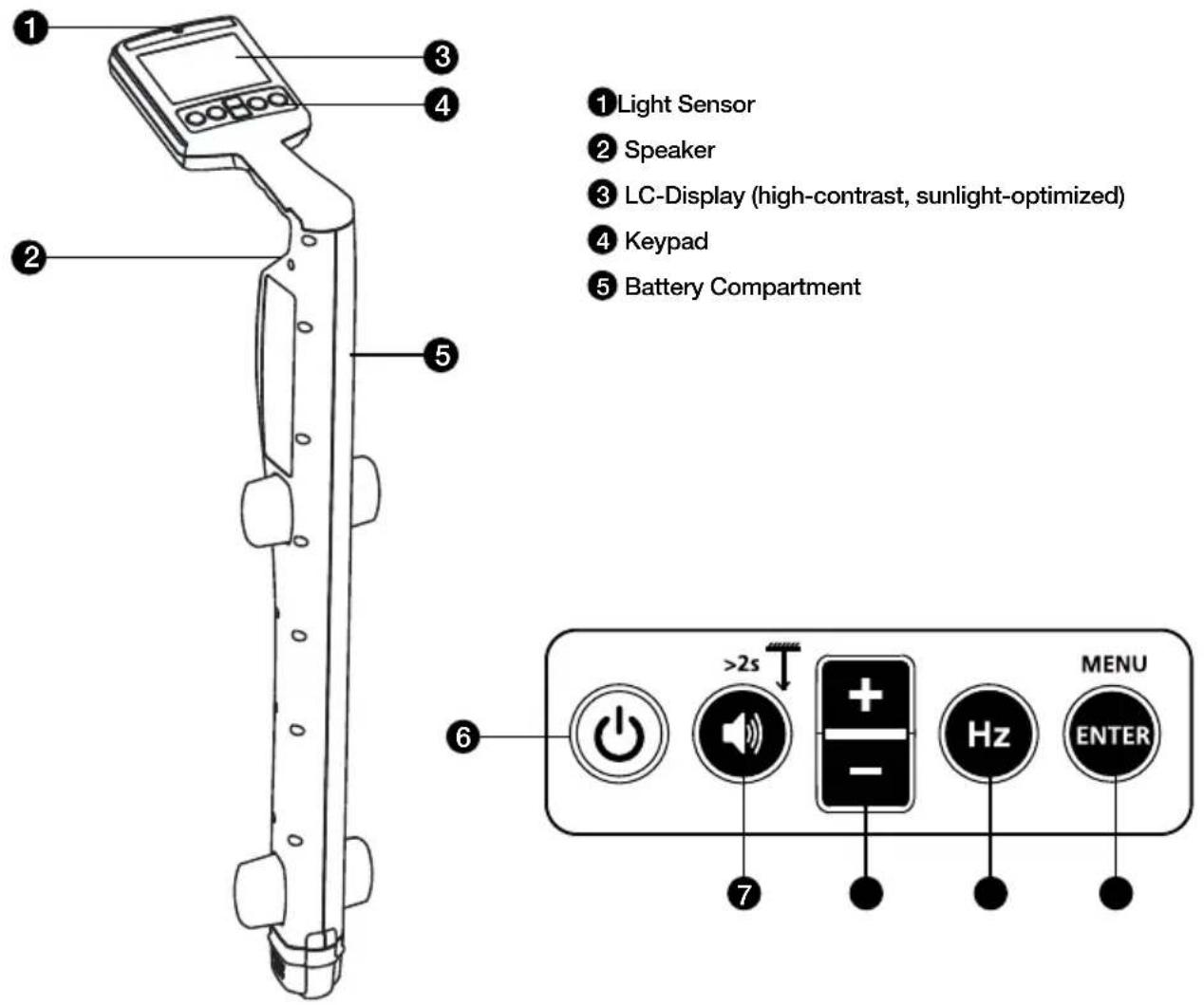
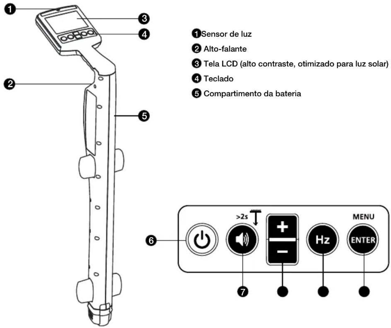
2.2 UAT-600-RE Receiver Controls and Display
Receiver Controls
text_image
① Light Sensor ② Speaker ③ LC-Display (high-contrast, sunlight-optimized) ④ Keypad ⑤ Battery Compartment ⑥ MENU >2s Hz ENTER ⑦6 Power On/Off ⏻ : Press for 2 seconds to turn the Receiver ON/OFF.
7 Volume/Depth :
• Volume – Press momentarily to change between mute, low, med and hi volume levels.
- Depth Measurement – Press and hold (> 2 seconds) until depth measurement indication appears on the screen.
8 +/—: Displays sensitivity adjustment on the main screen and for up/down selection in menu screen.
9 Hz Hz : Press momentarily to toggle between available frequency options.
| 8 kHz* 8 kHz Active Mode* | |
| 33 kHz 33 kHz Active Mode | |
| 50 Hz / 60 Hz Power Mode (50 or 60 Hz) | |
| Radio Radio Mode |
*8 kHz frequency is not used for connection with UAT-500-TE Transmitter. This frequency is provided to support optional UAT-600-TE Transmitter.
10 Enter/Menu – Press momentarily to enter Receiver settings menu.
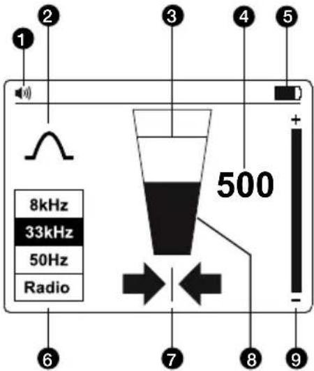
Receiver Display
The Receiver display features a high-contrast, sunlight-optimized black and white LCD screen. It also has an auto-backlight feature that activates in dark areas for optimized viewing.
text_image
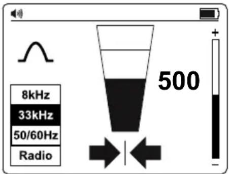
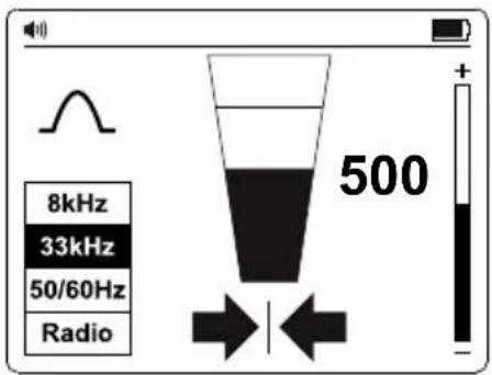
1 2 3 4 5 + 8kHz 33kHz 50Hz Radio 500 - 6 7 8 9①Speaker Volume
2 Locate Mode Indicator
③ Signal Level – Peak Indicator
4 Signal Level – Number Display (0-999 relates to 0-99.9%)
5 Battery Status Indicator
6 Signal Locating Frequency
7 Left-Right Arrows
8 Signal Level - Bar Graph
9 Sensitivity Setting Indicator
Left-Right Arrows
These arrows indicate distance from the position of the cable. Both left and right arrows will appear when exactly above the cable.

A solid arrow indicates that you are very close to or at the cable location.

A heavily shaded arrow indicates that you are approaching the cable location.

A lightly shaded arrow indicates that you are far from the cable location.
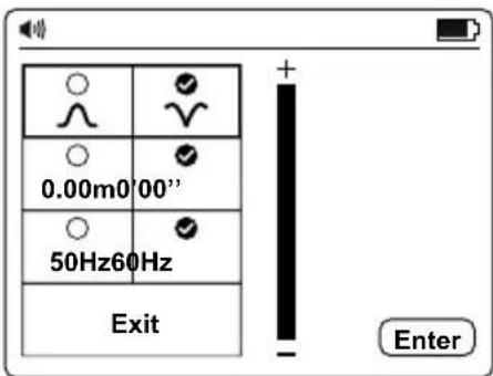
Receiver Setup
Set-up the Receiver before use by switching the unit on and pressing the "ENTER/MENU" button. The Settings Menu display will appear.
- Use the “+/-” buttons to scroll up and down the menu.
- Press "ENTER" to change the setting of a feature.
- To exit, scroll down to "Exit" and press "ENTER".
From the Settings Menu, it is possible to select:
- Antenna configuration - ∧ Peak or Null
- Measurements - Imperial (0 '00") or Metric (0.00 m)
- Locating frequency for Power Mode - 50 Hz or 60 Hz
Note: Some selections may not be available in all modes. If not available, the icon will be replaced by a — —.
text_image
0.00m0'00" 50Hz60Hz Exit EnterAntenna Configurations
 | Peak signal with left/right arrows. This configuration is satisfactory for general purpose locating. |
 | Null signal with left/right arrows. This configuration gives a sharp Null signal over the line but is less accurate than when in Peak Mode. Is useful for tracing long lines as the sharp Null signal is easy to trace. |
Using the Null Mode
To select Null Mode, switch the unit on and press "ENTER" to access the Settings Menu.
Select and exit the Settings Menu. The bar graph will now show a minimum signal over the line.
The left/right arrows will also indicate the position of the line.
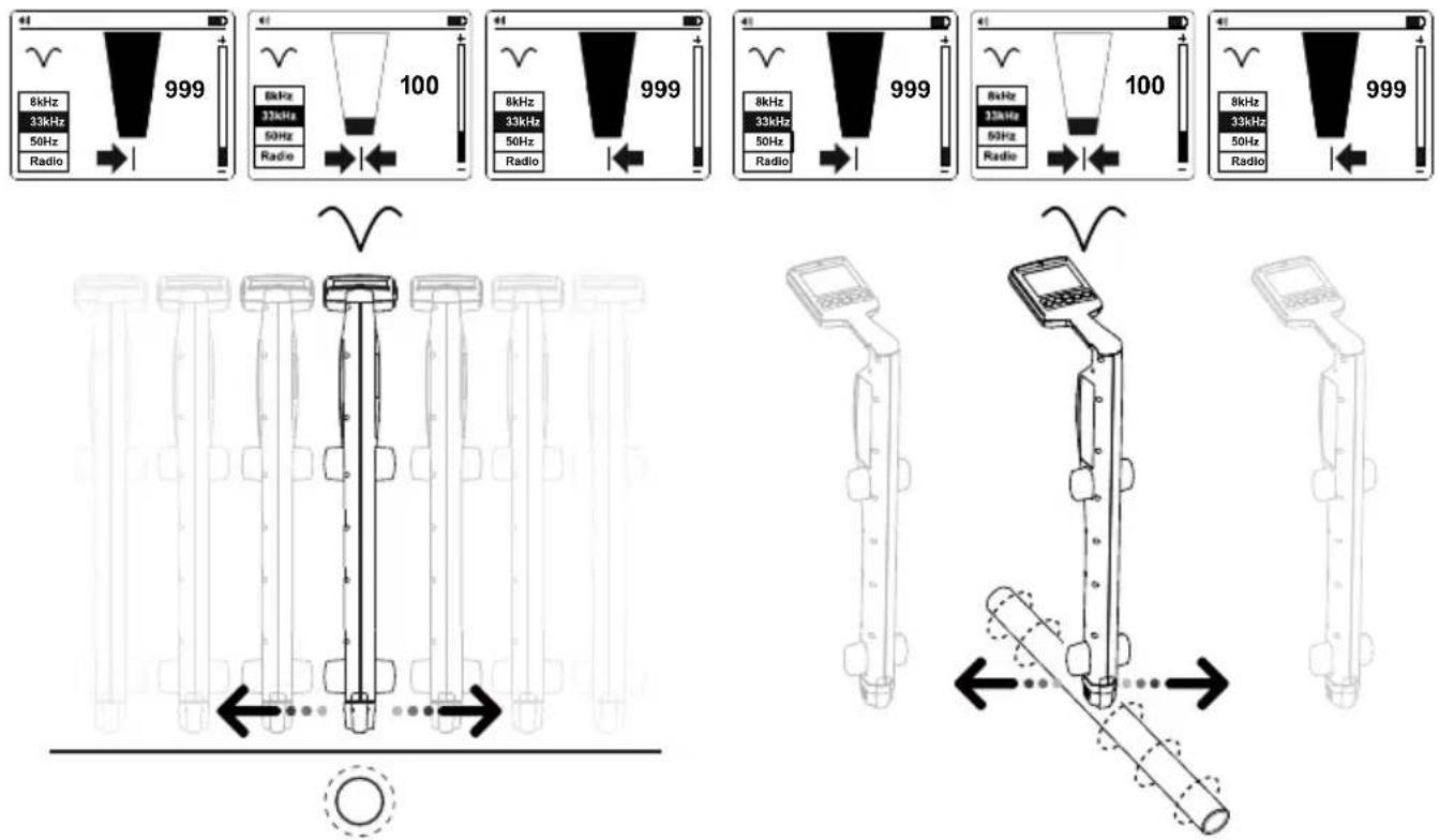
text_image
8kHz 33kHz 50Hz Radio 999 100 999 8kHz 33kHz 50Hz Radio 999 8kHz 33kHz 50Hz Radio 999 8kHz 33kHz 50Hz Radio 100 8kHz 33kHz 50Hz Radio 999Note: Use the Null Mode with caution as it is not as accurate as Peak Mode. The Null Mode is useful in detecting the approximate position of a line when tracing over a long distance.
2.3 UAT-600-RE Receiver Alerts
Screen Alerts
These alerts appear to the right-hand side of the screen and can appear at any time.
| Service | Indicates that the unit is not calibrated. This is usually a factory setting. Service should be contacted. |
| Battery low | Indicates less than 10% battery remaining. |
| Signal overload | Indicates that the signal is too large to process correctly. No damage will occur to the electronics, but measurements will be affected. This condition is very unusual. |
| Battery very low | When this icon appears the battery voltage is so low that it is not possible to operate the locator. Replace or recharge batteries to continue. |
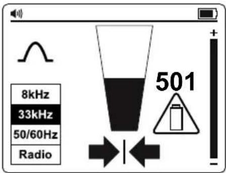
text_image
8kHz 33kHz 50/60Hz Radio 501Depth Measurement Related Alerts
These alerts are associated with depth measurements and only appear within the depth pop-up screen section.
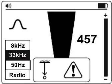
text_image
8kHz 33kHz 50Hz Radio 457Depth Related Alerts
 Signal Abnormal Signal Abnormal | Not possible to compute depth because the signal is too noisy, too weak or too strong. |
 Overhead Signal Overhead Signal | Not possible to compute depth because of a strong signal radiating from above (i.e., an overhead cable). |
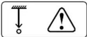
 Shallow Utility Shallow Utility | The unit has detected a shallow utility (less than 10 cm).Caution is required when excavating. |
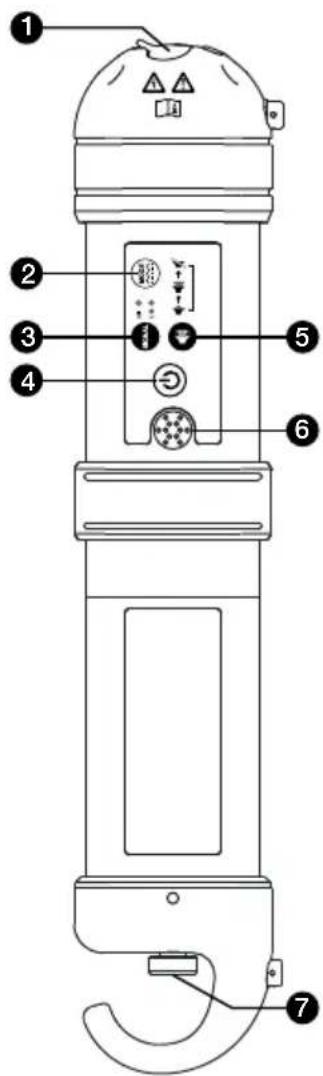
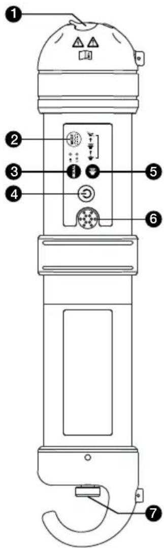
2.4 UAT-500-TE Transmitter Controls and Display
Transmitter Controls
text_image
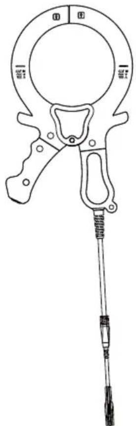
Diagram of a vertical device with numbered parts and control buttons, likely for labeling or assembly instructions.2.5 SC-600-EUR Signal Clamp (optional)
In many situations, it is either not possible to gain access to a cable for making an electrical contact or it is not safe to do so. The optional Signal Clamp accessory provides an efficient and safe method of applying a locate signal to a cable, enabling the Transmitter to induce a signal through the insulation into the wires or pipes. The clamp works on low impedance closed circuits only.
1 Terminals for direct test leads connection (de-energized systems only) and signal clamp
2 Pulse/Continuous: Press momentarily to change between default Continuous and Pulse Modes for better performance in high noise environments
3 Signal strength: Press momentarily to change between Hi for maximum signal strength, or Lo for better battery efficiency
4 Power ON/OFF: Press for 2 seconds to turn the Transmitter ON/OFF
⑤ Volume: Press momentarily to change between low, hi and mute volume levels
⑥ Speaker (tone indicates connection quality)
7 Battery housing cover
natural_image
Line drawing of a clamp or measuring tool with handle, grip, and screwdriver (no text or symbols)3. MAIN APPLICATIONS
| Application Receiver setting Transmitter | Setting Note | ||
| Locating energized 50/60 Hz cables carrying current | Power Mode 50 Hz or 60 Hz | No Transmitter needed | Receiver will detect signal from any energized 50/60 Hz cable carrying current Section 3.2 |
| Identifying location all metallic utilities: pipes*, energized and de-energized cables | Radio Mode | Receiver will detect multiple utilities conducting the signal Section 3.3 & 3.4 | |
| 33 kHz | Induction Mode | ||
| Tracing individual pipes* or cable (de-energized cables only) | 33 kHz | Direct test lead connection | Receiver will detect signal only from individual cable/pipe connected to the Transmitter Section 3.5 & 3.6 |
| Clamp | |||
*Tracing of non-metallic pipes and conduits is possible after inserting metal fish tape or cable
3.1 General Tracing Techniques for All Applications
Receiver Locating
- Turn the Receiver on by pressing the power button for two seconds. Select the desired locating frequency. Hold the Receiver vertically.
- Adjust the sensitivity, using the “+/-” buttons so that the bar graph reading just begins to show some movement. The sensitivity control should be at, or close to, maximum sensitivity.
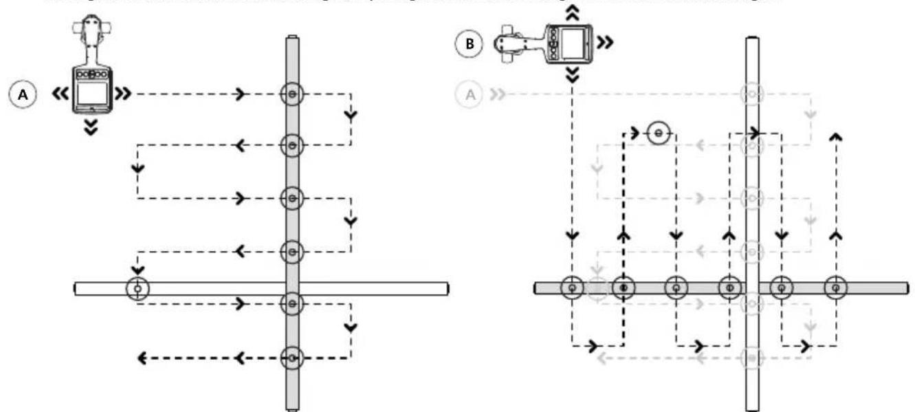
- Keeping the Receiver vertical and in front of your body, walk across the area to be checked, then follow in a grid pattern.
Note that there will be no sound from the speaker until the meter reading is above full scale approximately 10%.
Note that objects perpendicular to the receiver will not be detected (white objects in drawings A and B). The Receiver will detect objects that are parallel or under angle (gray objects in drawings A and B). After performing the initial grid search as shown in drawing A, repeat grid search at 90 degrees as shown in drawing B.
flowchart
graph TD
    subgraph_Panel_A["Control Panel A"]
        A1((A)) --> A2((B))
        A2 --> A3((A))
        A3 --> A4((B))
        A4 --> A5((A))
        A5 --> A6((B))
        A6 --> A7((A))
        A7 --> A8((B))
    end

    subgraph_Panel_B["Control Panel B"]
        B1((B)) --> B2((A))
        B2 --> B3((A))
        B3 --> B4((B))
        B4 --> B5((A))
        B5 --> B6((B))
        B6 --> B7((A))
        B7 --> B8((B))
    end

    A1 -.-> A2
    A2 -.-> A3
    A3 -.-> A4
    A4 -.-> A5
    A5 -.-> A6
    A6 -.-> A7
    A7 -.-> A8
    A8 -.-> B1
    B1 -.-> B2
    B2 -.-> B3
    B3 -.-> B4
    B4 -.-> B5
    B5 -.-> B6
    B6 -.-> B7
    B7 -.-> B8
    B8 -.-> B9
    style Panel_A fill:#f9f,stroke:#333
    style Panel_B fill:#bbf,stroke:#333
Plan View
- If at any time the meter reading starts to increase, carefully move the locator forward and back, left to right to detect the maximum signal. Use the bar graph to help confirm the correct position. If the bar graph exceeds the maximum value, adjust the sensitivity to bring the reading back within the limits of the bar graph using “+/-” buttons.
If the reading is off scale (too great or too small), then pressing the ☐/☐ " buttons together will automatically adjust the sensitivity to bring the meter deflection to 50%.
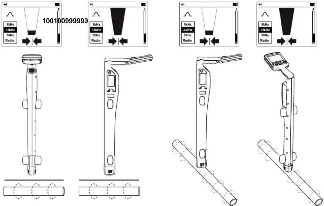
- Rotate the Receiver on its axis to obtain the maximum signal. This indicates that the Receiver is directly over the line and aligned with the direction of the cable. The direction can also be verified by rotating until the smallest signal is detected – the Receiver is then perpendicular with the cable/pipe.
text_image
100100999999 8kHz 33kHz 50Hz Radio 8kHz 33kHz 50Hz Radio 8kHz 33kHz 50Hz Radio- Walk along the path of the cable and trace it by moving the Receiver left to right to find the highest signal.
3.2 Power Mode 50/60 Hz - Passive Location of Energized Cables and Power Lines
Power signals are created by mains power running in the supply cables. These signals are 50 or 60 Hz depending on the region (for example, Europe has 50 Hz power and the United States has 60 Hz power). This frequency can be adjusted on the Receiver.
When electrical power is distributed throughout the network, some of the power finds its way back to the power station via the ground. These stray currents can jump onto pipes and cables and also create power signals.
There must be enough electrical current flowing to create a detectable signal. For instance, a live cable that is not in use may not radiate a detectable signal. A very well balanced cable (exactly the same current flowing in live and neutral) will cancel out and may not create a signal. In practice this is unusual as there are usually enough imbalances in the cable to create a good detectable signal.
- Turn the Receiver on by pressing the power button for two seconds.
- Press "Hz" button repeatedly until the correct frequency is selected. To change frequency between 50 or 60 Hz refer to the UAT-600-RE Receiver Controls and Display section 2.2.
- Follow the steps as described in the Receiver Locating section 3.1.
3.3 Radio Mode - Passive Location of Utilities
Radio signals are created by low frequency radio transmitter and are used for broadcasting and communications. They are positioned throughout the world. As the frequencies are very low, the signals tend to penetrate and hug the curvature of the earth. When the signals cross a long conductor such as a pipe or cable, the signals are re-radiated. It is these re-radiated signals that can be detected by Radio Mode.
Locating radio signals is very similar to detecting power signals as they are both passive. With the Radio Mode method, you will detect metallic utilities, such as pipes, as well as energized and de-energized cables. Tracing of non-metallic pipes and conduits will be possible after inserting metal fish tape or cable.
text_image
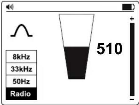
8kHz 33kHz 50Hz Radio 510- Turn the Receiver on by pressing the power button for two seconds.
- Press the "Hz" button repeatedly until Radio is selected.
- Follow the steps as described in the Receiver Locating section 3.1.

The Left/Right arrows are not active during passive location
3.4 Induction Mode - Locating Utilities
Induction Mode is particularly useful for identifying the location of multiple buried utilities before digging. Induction Mode can be also used for tracing individual cables where there is no access to the line to connect test leads or a clamp. However, this method may not be reliable if adjacent lines are present because the signal will be also applied to these lines.
Without the test leads or signal clamp connected to the Transmitter, the Transmitter will automatically start to radiate a signal around it using an internal antenna. These signals will penetrate the ground and couple onto buried lines. The signal will then travel along the line which can be detected with the Receiver.
With the Induction Mode method, you will detect metallic utilities, such as pipes, as well as energized and de-energized cables. Tracing of non-metallic pipes and conduits will be possible after inserting metal fish tape or cable.
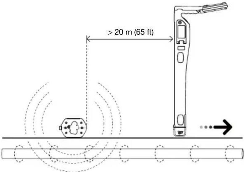
Induction Mode - Setting Up the Transmitter
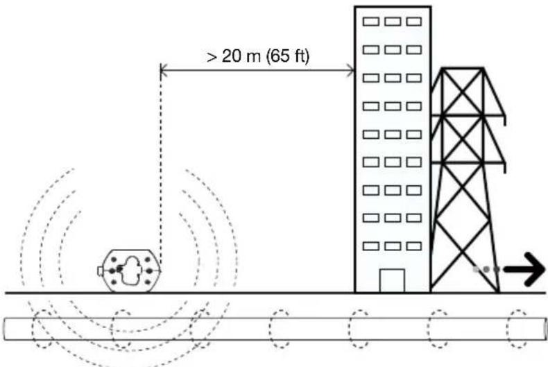
When using Induction Mode, place the Transmitter at least 65 feet (20 m) away from any structure such as building or a tower to avoid signal interference. Before tracing, take a visual inspection of the area looking for clues were the buried utility might be present, such as transformers, manholes, street or parking lamps, etc.
text_image
> 20 m (65 ft)The signal will radiate around the Transmitter as well as below it, so it is recommended that when applying a signal using Induction Mode, a distance of at least 65 feet (20 m) is kept from the Transmitter when pinpointing or taking depth readings. While locating closer than 65 feet is possible, the operator should be aware that the signal directly received from the Transmitter may be strong enough to influence the results.
text_image
> 20 m (65 ft)
Avoid placing the Transmitter over metallic manhole covers as this will severely reduce the effectiveness of the Transmitter, and in extreme cases, cause damage to the Transmitter's circuitry.
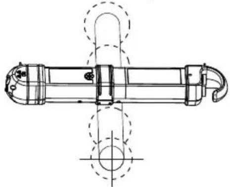
- Turn the Transmitter on by pressing the power button for two seconds.
- Place the Transmitter over the suspected location of the line, positioning it so that it is perpendicular to the line.
natural_image
Technical line drawing of a mechanical component with symmetrical features and centerlines (no text or symbols)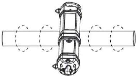
natural_image
Technical line drawing of a mechanical assembly with cylindrical components and mounting holes (no text or symbols)- Press the Signal button to switch between Hi and Lo signal strength. Lo signal level uses less energy and helps to preserve batteries. Increase the level if the resulting signal strength is poor. Increasing the signal unnecessarily may result in the signal being induced into unwanted lines.
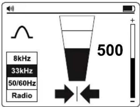
Induction Mode - Locating with the Receiver
-
Turn the Receiver on by pressing the power button for two seconds.
-
Press "Hz" button repeatedly until 33 kHz is selected.*
-
Follow the steps as described in the Receiver Locating section 3.1, using the Left/Right arrow indicators to quickly assess location of the wire.
-
Optionally measure the depth of the wire. Refer to the Taking Depth and Current Measurements section 4.3 for details.
For better accuracy, after the initial location of a utility is detected, move the Transmitter directly over it in case it was not placed precisely in the beginning of the search.
Where the signal is distorted, the arrows may indicate a different target position than the largest bar graph reading. In this situation, always use the bar graph to pinpoint the line as it is influenced less than the Left/Right arrows in a distorted signal field.
* 8 kHz frequency is not used for connection with UAT-500-TE Transmitter. This frequency is provided to support optional UAT-600-TE Transmitter.
text_image
8kHz 33kHz 50/60Hz Radio 5003.5 Direct Test Leads Connection Mode - Tracing an Individual Pipe or Cable
Direct connection with test leads is the most reliable method to trace individual cable or a pipe.
WARNING
- Only authorized personnel should make connections to cables.
- The Transmitter can be connected ONLY to de-energized wires or pipes.
- Do not touch metal parts of the connection clips when connecting to the line or when the Transmitter is on as they may exceed 30 V rms.
- For shielded cables, always connect to the sheath of that cable. The sheath will stop the tracing signal if the Transmitter is connected to one of the internal wires.
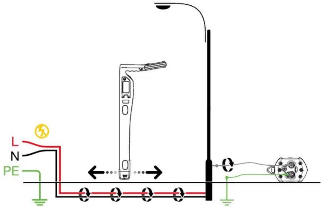
text_image
L N PEAvoiding signal cancellation problems with a separate ground connection
The signal generated by the Transmitter creates an electromagnetic field around the wire. This field is what is detectable by the Receiver. The clearer this signal, the easier it is to trace the wire. If Transmitter is connected to two adjacent wires on the same circuit (for example, hot and neutral wires on a Romax cable), the signal travels in one direction through the first wire and then returns (in opposite direction) through the second. This causes the creation of two electromagnetic fields around each wire with opposite direction. These opposing fields will partially or completely cancel each other out, making wire tracing difficult if not impossible.
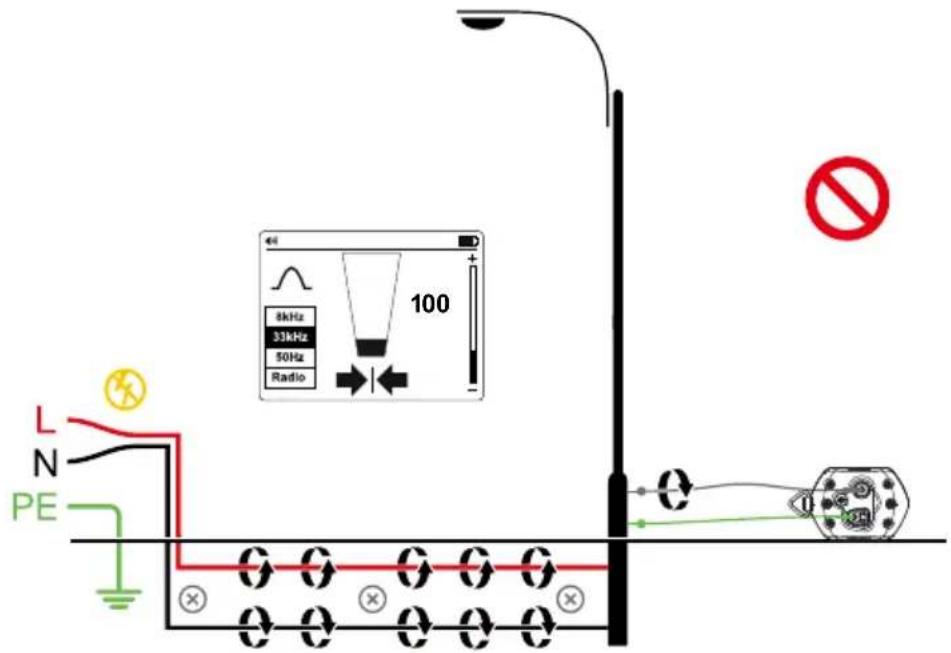
text_image
L N PE 8kHz 33kHz 50Hz Radio 100 NoTo avoid the cancellation effect, a separate ground connection method should be used. The gray test lead of the Transmitter should be connected to the hot wire of the circuit you wish to trace, and the green lead to a separate ground, such as water pipe, ground stake, metal grounded structure of the building, or outlet ground connection of an outlet on a different circuit. It is important to understand that an acceptable separate ground is NOT the grounding terminal of any receptacle on the same circuit as the wire you wish to trace.
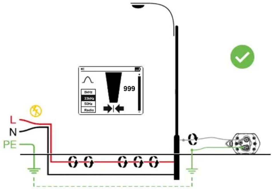
text_image
8kHz 33kHz 50Hz Radio 999 L N PEDirect Test Leads Connection Mode – Setting Up the Transmitter
- Turn the Transmitter on by pressing the power button for two seconds.
- Connect the green and gray test leads to the Transmitter inputs. The Transmitter will switch automatically to Direct Connection Mode.
- Insert the ground stake into the ground a few meters perpendicular to the line. Connect the green lead to the ground stake with an alligator clip.
- Connect the gray test lead to the target line. If connecting to the electrical cable, make sure the wires are de-energized.
- Press the Signal button to switch between Hi and Lo signal strength. Lo signal level uses less energy and helps to preserve batteries. Increase the level if the resulting signal strength is poor. Increasing the signal unnecessarily may result in the signal “bleeding off” onto other services and creating misleading “ghost” signals. It will also drain more power from the battery.
Note: When connected, the Transmitter will emit a beep tone. The better the connection to the line and ground, the lower the tone will be. Check for a good connection by disconnecting and then reconnecting the gray lead.
Things that can affect the quality of connection are a rusty pipe connection point (clean the connection area with a wire brush) or poor grounding. To improve the connection quality due to poor grounding, try inserting the stake into damp ground. If necessary, dampen the surrounding ground with water. If grounding is still an issue, try connecting test lead to a manhole cover surround. Avoid connecting to fence railings as these may create return signal currents along the fencing that will interfere with the locating signal.
When connecting to large diameter pipes and cables, it is sometimes not possible to find a suitable projection to apply the alligator clip. If the material is ferrous, use a magnet to make contact to the line and then attach the alligator clip to a magnet. For example: making a connection to a street lighting circuit. Usually it is practice to connect the sheath of a lighting cable to the metallic inspection cover of a street lamp. Making a connection to the inspection plate will induce a signal to the cable via the plate and sheath. Normally, there is no projection on the plate on which to clip so using a magnet on the plate provides a suitable clipping point.
Direct Test Leads Connection Mode – Locating with the Receiver
- Turn the Receiver on by pressing the power button for two seconds.
- Match the frequency of the Transmitter by pressing the "Hz" button repeatedly. Select 33 kHz frequency.
Note: 8 kHz frequency is not used for connection with UAT-500-TE Transmitter. This frequency is provided to support optional UAT-600-TE Transmitter. - Follow the steps as described in the Receiver Locating section 3.1.
- Use the Left/Right arrow indicators to quickly assess location of the wire.
- Optionally measure the depth of the wire. Refer to the Taking Depth and Current Measurements section 4.3 for details.
text_image
8kHz 33kHz 50/60Hz Radio 5003.6 Signal Clamp Accessory – Tracing an Individual Pipe or Cable
text_image
8kHz 33kHz 50/60Hz Radio 500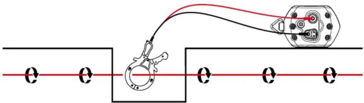
text_image
Diagram showing a cable or wire connection with a clamp and electrical component, labeled with 'Q' on both sides.In many situations, it is either not possible to gain access to a cable for making an electrical contact or it is not safe to do so. The Signal Clamp provides an efficient and safe method of applying a locate signal to a cable.
When using the Signal Clamp, it is best if both ends of the target cable are grounded to enable the current to flow. When applying a clamp close to a grounding point where multiple grounds or a grounding bus exists, ensure that the clamp is placed around the target line and not to the ground bus/other grounds to reduce the effects of the transmitted signal also being applied to an unwanted line.
Signal Clamp Accessory – Setting Up the Transmitter
- Turn the Transmitter on by pressing the power button for two seconds.
- Connect the black and red test leads of the Signal Clamp to the Transmitter inputs.
-
Clamp the Signal Clamp around the target line.
-
Press Signal button to switch between Hi and Lo signal strength. Lo signal level uses less energy and helps to preserve batteries. Increase the level if resulting signal strength is poor. Increasing the signal unnecessarily may result in the signal "bleeding off" onto other services and creating misleading "ghost" signals. It will also drain more power from the battery.
Signal Clamp Accessory - Locating with the Receiver
- Turn the Receiver on by pressing the power button for two seconds.
- Match the frequency of the Transmitter by pressing the "Hz" button repeatedly. Select 33 kHz frequency.
- Follow the steps as described in the Receiver Locating section 3.1.
- Use the Left/Right arrow indicators to quickly assess location of the wire.
- Optionally measure the depth of the wire. Refer to the Taking Depth and Current Measurements section 4.3 for details.

text_image
8kHz 33kHz 50/60Hz Radio 5004. SPECIAL APPLICATIONS
4.1. Locating Non-Metallic Pipes and Sewer Lines
The UAT-500-EUR locator can indirectly trace non-metallic conduits and pipes.
- Insert fish tape or wire inside the conduit or pipe. For sewer lines, use the sewer drain cleaning machine to insert a cleaning cable.
- Follow steps as described in the Direct Test Leads Connection Mode – Tracing an Individual Pipe or Cable section 3.5. Connect the gray test lead to the fish tape or the drain cable.
The Receiver will pick up the signal conducted by the fish tape or wire, indicating the location of the non-metallic pipe.
4.2. Taking Depth Measurements
Depth measurement is only available when the Receiver is set to 33 kHz frequency. It is NOT available in 50/60 Hz or Radio Modes.
To take a depth and current measurement, first pinpoint the position of the line. Place the tip of the Receiver on the ground making sure it is vertical and across the line. Press and hold the
"button until the screen changes to display a dialog box.
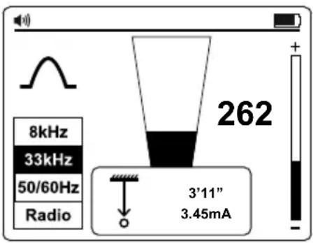
text_image
8kHz 33kHz 50/60Hz Radio 262 3'11" 3.45mAChecking for depth errors due to signal distortion
One way to determine if the depth measurement is likely to have been affected by distortion is to take a depth reading at ground level, then raise the Receiver a known distance off the ground (such as one foot). Retake the depth reading at the new depth and confirm that the depth has increased by this amount. If the depth has changed by something other than the actual change, then the readings should be treated as suspect.
Distorted signals will cause the located line position to be displaced from the actual position. The errors are more pronounced using the arrows in Null Mode than the Peak Mode bar graph. Hence, if the arrow/null position and peak bar graph position indicate differently, the signal likely distorted and the readings should be treated with caution.
⚠ WARNING
Never mechanically dig over the path of a buried pipe or cable. Always dig carefully.
4.3. Advanced Locating Techniques – Two Person Swap
- Set up the Transmitter as described in the Induction Mode – Locating Utilities section 3.4.
- Turn the Receiver on by pressing the power button for two seconds and select 33 kHz frequency by pressing Hz button.
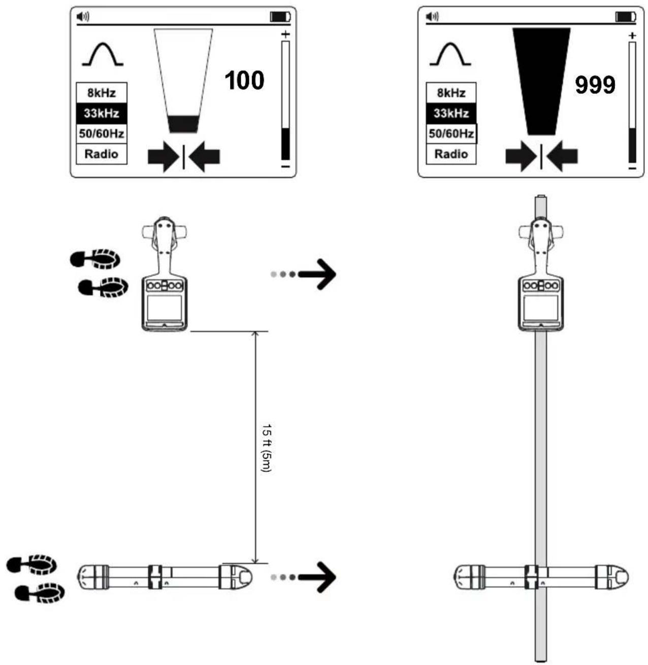
- Select the area to be checked. One person holds the Transmitter with the handle in line with the direction of movement and the other holds the Receiver (as shown below).
- Stand at least 15 feet (5 m) apart holding the equipment as below, with the Transmitter and Receiver in line with the direction of movement.
- Adjust the sensitivity of the Receiver so that the meter reads approximately 20% signal strength.
- Walk slowly across the site keeping parallel with each other. As a service is approached, the signal level on the Receiver will increase. When the signal is at a maximum, stop the Transmitter and place it on the ground. Then pinpoint the position of the service with the Receiver as described in the Receiver Locating section 3.1. Mark this position and plot the route across the site if necessary.
- Continue to the sweep across the site and then, if possible, repeat the process at 90 degrees to the sweep already completed.
5. MAINTENANCE
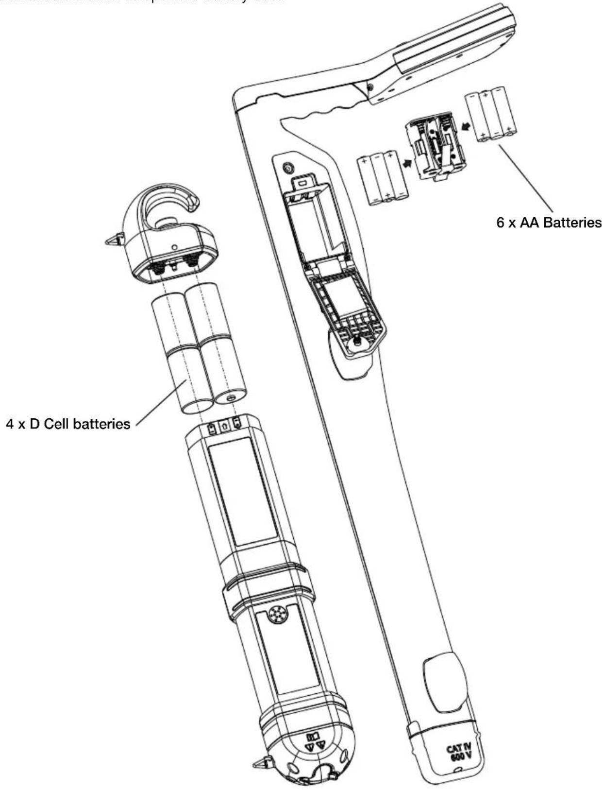
5.1. Battery Replacement
Use a flat screw driver to open the battery door.
text_image
4 x D Cell batteries 6 x AA Batteries CAT TV 600 VUAT-600-REUAT-505-TE
6. SPECIFICATIONS
| UAT-500-TE Transmitter | |
| Operating voltage De-energized circuit only for Direct Connection Mode | |
| Transmitting frequency 33 kHz | |
| Tracing modes | De-energized:- Induction Mode- Direct Connection Mode- Clamp Mode |
| Transmitting mode power output Max. 1 watt | |
| Output voltage Max. 35 V rms | |
| Output current Max. 100 mA rms | |
| Visual signal indication Two LEDs indicating LO and HI signal | |
| Audio signal indication | Continuous Signal Mode: Continuous audio tonePulse Signal Mode: Fast pulsed audio tone |
| Compatible receiver UAT-600-RE Receiver | |
| Compatible accessories | SC-600-EUR Signal ClampTL-UAT-500 Test lead set |
| Operating temperature and humidity | -20 °C to 50 °C (-4 °F to 122 °F), ≤ 80% RH |
| Storage temperature and humidity | -40 °C to 60 °C (-40 °F to 140 °F), ≤ 80% RH |
| Operating altitude < 2000 m (< 656 ft) | |
| Pollution degree 2 | |
| IP-rating IP54 | |
| Power supply Four (4) 1.5 V D cell alkaline batteries | |
| Battery life Approx. 12 hours at 21 °C (70 °F) (Typical) | |
| Low battery indication | Both LO and HI LEDs blink every 1.5 seconds and audio sound pulses every 1.5 seconds |
| Agency approval | CE K |
| Safety compliance | IEC 61010-1, CSA/UL 61010-1,IEC 61010-031, CSA/UL 61010-031 (test leads) |
| Electromagnetic Compatibility | IEC 61326-1 Korea (KCC): Class A Equipment (Industrial Broadcasting & Communication Equipment) [1][1] This product meets requirements for industrial (Class A) electromagnetic wave equipment and the seller or user should take notice of it. This equipment is intended for use in business environments and is not to be used in homes. |
| Size (H x W x L) | Approx. 460 x 90 x 65 mm (18.1 x 3.5 x 2.6 in) |
| Weight | Approx. 1.77 kg (3.9 lb) (batteries installed) |
| UAT-600-RE Receiver | |
| Operating voltage 0 to 600 V | |
| Tracing modes | Active tracing: 33 kHz (32,768 Hz) and 8 kHz (8,192 Hz)Passive tracing: 50 / 60 Hz and Radio |
| Locating modes Peak and Null | |
| Sensitivity adjustment(gain control) | Yes |
| Depth measurement Up to 6 m (20 ft) | |
| Depth measurement accuracy | 0.1 m (4 in) to 3m (10 ft): ± 3 %3 m (10 ft) to 6 m (20 ft): ± 5 % |
| Sensitivity at 1 m (typical) | Power: 2 mARadio: 20 μA8 kHz: 5 μA33 kHz: 5 μA |
| Display backlight Automatic | |
| Audio indication Increasing closer to the signal | |
| Compatible transmitter UAT-500-TE + UAT-600-TE Transmitter | |
| Display 109 mm (4.3 in), 320 x 240 BW outdoor LC-Display with auto backlight | |
| Update rate Instantaneous | |
| Operating temperature and humidity | -20 °C to 50 °C (-4 °F to 122 °F), ≤90% RH |
| Storage temperature and humidity | -40 °C to 60 °C (-40 °F to 140 °F), ≤90% RH |
| Operating altitude < 2000 m (< 6561 ft) | |
| Pollution degree 2 | |
| IP-rating IP54 | |
| Drop proof | 1 m (3.28 ft) |
| Power supply | Six (6) 1.5 V AA alkaline batteries |
| Auto power off | 15 minutes idleWill auto turn off after 15 min of no button pressing |
| Battery life | Approx. 35 hours at 21 °C (70 °F) (Typical) |
| Low battery indication | and/or at upper right corner of the screen |
| Measurement Category | CAT IV 600 V |
| Agency approval | CE C E C |
| Safety compliance | IEC 61010-1, IEC 61010-2-033CSA/UL 61010-1, CSA/UL 61010-2-033 |
| Electromagnetic Compatibility | IEC 61326-1 Korea (KCC): Class A Equipment (Industrial Broadcasting & Communication Equipment) [1][1] This product meets requirements for industrial (Class A) electromagnetic wave equipment and the seller or user should take notice of it. This equipment is intended for use in business environments and is not to be used in homes. |
| Size (H x W x L) | Approx. 302 x 120 x 779 mm (11.9 x 4.7 x 30.7 in) |
| Weight | Approx. 1.9 kg (4.2 lb) (batteries installed) |
| SC-600-EUR Signal Clamp | |
| Operating voltage & current 0 to 6 | 00 V, 100 A max. |
| Operating frequency 33 kHz (32,768 Hz) and 8 kHz (8,192 Hz) | |
| Signal voltageOutput (nominal) | 23 V rms at 8 kHz30 V rms at 33 kHz |
| Operating temperature and humidity | -20 °C to 50 °C (-4 °F to 122 °F), ≤ 90 % RH |
| Storage temperature and humidity | -40 °C to 60 °C (-40 °F to 140 °F), ≤90% RH |
| Operating altitude < 2000 m (< 6561 ft) | |
| Pollution degree 2 | |
| IP-rating IP54 | |
| Drop proof 1 m (3.28 ft) | |
| Measurement Category CAT IV 600 V | |
| Agency approval | CEKCE |
| Safety compliance | IEC 61010-1, IEC 61010-2-032CSA/UL 61010-1, CSA/UL 61010-2-032 |
| Electromagnetic Compatibility | IEC 61326-1 Korea (KCC): Class A Equipment (Industrial Broadcasting & Communication Equipment)[1][1] This product meets requirements for industrial (Class A) electromagnetic wave equipment and the seller or user should take notice of it. This equipment is intended for use in business environments and is not to be used in homes. |
| Size (H x W x L) Approx. 295 x 180 x 37 mm (11.6 x 7.1 x 1.4 in) | |
| Weight Approx. 0.85 kg (1.9 lb) | |
| TL-UAT-500 Test leads | |
| Operating voltage and current 50 V max, 1 A | |
| Leads length 3.5 m (11.5 ft) | |
| Compatible transmitter | UAT-500-TE Transmitter |
| Operating temperature and humidity | -20 °C to 50 °C (-4 °F to 122 °F), ≤ 80% RH |
| Storage temperature and humidity | -40 °C to 60 °C (-40 °F to 140 °F), ≤ 80% RH |
| Operating altitude | < 2000 m (< 6561 ft) |
| Pollution degree | 2 |
| Agency approval | CE |
| Safety compliance | IEC 61010-031, CSA/UL 61010-031 |
| Size (H x W x L) | Approx. 230 x 90 x 80 mm (9 x 3.5 x 3.1 in) |
| Weight | Approx. 0.5 kg (1.1 lb) |
UAT-505-EUR
text_image
Diagram of a vertical device with numbered parts and control buttons, likely for labeling or assembly instructions.2.5 Signalzange SC-600-EUR (optional)
natural_image
Line drawing of a clamp or measuring tool with handle, grip, and screwdriver (no text or symbols)3. HAUPTANWENDUNGEN
natural_image
Technical line drawing of a mechanical component with symmetrical features and dashed circular annotations (no text or symbols)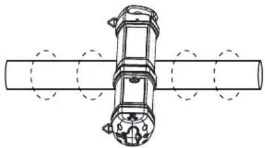
natural_image
Technical line drawing of a mechanical device with cylindrical body and flanged ends, no text or symbols presenttext_image
Diagram showing a cable or wire connection between two rectangular blocks with labeled 'C' and 'O' on the left side, connected to a mechanical clamp.text_image
Labeled diagram of a medical or laboratory device with numbered parts for identificationtext_image
Diagram of a vertical device with numbered parts and control buttons, likely for labeling or assembly instructions.natural_image
Line drawing of a clamp or measuring tool with handle, grip, and screwdriver (no text or symbols)3. APPLICAZIONI PRINCIPALI
flowchart
graph TD
    subgraph_Channel_A["Channel A"]
        direction LR
        A1["Input"] --> A2["Device Icon"]
        A2 --> A3["Arrow to Channel A"]
        A3 --> A4["Arrow to Channel A"]
        A4 --> A5["Arrow to Channel A"]
        A5 --> A6["Arrow to Channel A"]
        A6 --> A7["Arrow to Channel A"]
        A7 --> A8["Arrow to Channel A"]
        A8 --> A9["Arrow to Channel A"]
        A9 --> A10["Arrow to Channel A"]
        A10 --> A11["Arrow to Channel A"]
        A11 --> A12["Arrow to Channel A"]
        A12 --> A13["Arrow to Channel A"]
        A13 --> A14["Arrow to Channel A"]
        A14 --> A15["Arrow to Channel A"]
        A15 --> A16["Arrow to Channel A"]
        A16 --> A17["Arrow to Channel A"]
        A17 --> A18["Arrow to Channel A"]
        A18 --> A19["Arrow to Channel A"]
        A19 --> A20["Arrow to Channel A"]
    end
    subgraph_Channel_B["Channel B"]
        direction LR
        B1["Device Icon"] --> B2["Arrow to Channel B"]
        B2 --> B3["Arrow to Channel B"]
        B3 --> B4["Arrow to Channel B"]
        B4 --> B5["Arrow to Channel B"]
        B5 --> B6["Arrow to Channel B"]
        B6 --> B7["Arrow to Channel B"]
        B7 --> B8["Arrow to Channel B"]
        B8 --> B9["Arrow to Channel B"]
        B9 --> B10["Arrow to Channel B"]
        B10 --> B11["Arrow to Channel B"]
        B11 --> B12["Arrow to Channel B"]
        B12 --> B13["Arrow to Channel B"]
        B13 --> B14["Arrow to Channel B"]
        B14 --> B15["Arrow to Channel B"]
        B15 --> B16["Arrow to Channel B"]
        B16 --> B17["Arrow to Channel B"]
        B17 --> B18["Arrow to Channel B"]
        B18 --> B19["Arrow to Channel B"]
        B19 --> B20["Arrow to Channel B"]
    end
    Note: The diagram shows multiple parallel paths from Channel_A to Channel_B with directional arrows indicating signal flow or feedback paths.
Veduta in pianta
natural_image
Technical line drawing of a mechanical component with symmetrical features and centerlines (no text or symbols)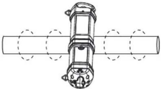
natural_image
Technical line drawing of a mechanical assembly with cylindrical components and mounting holes (no text or symbols)text_image
Diagram showing a cable or wire connection between two rectangular blocks with labeled points and a connector, likely illustrating electrical or mechanical wiring.text_image
Labeled diagram of a medical or laboratory device with numbered parts for identificationtext_image
Diagram of a vertical device with numbered parts and control buttons, likely for labeling or assembly instructions.natural_image
Line drawing of a clamp or measuring tool with handle, grip, and screwdriver (no text or symbols)text_image
> 20 m (65 pies)text_image
> 20 m (65 pies)
natural_image
Technical line drawing of a mechanical component with symmetrical features and dashed circular annotations (no text or symbols)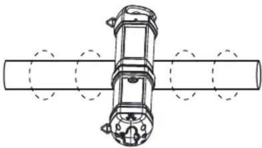
natural_image
Technical line drawing of a mechanical device with circular features, no text or symbols presenttext_image
Diagram showing a cable or wire connection with a clamp and electrical component, labeled with 'Q' on both sides.- PRINCIPALES APPLICATIONS ....10
text_image
Labeled diagram of a medical or laboratory device with numbered parts for identification.text_image
Diagram of a vertical device with numbered parts and control buttons, likely for labeling or assembly instructions.2.5 Pince de signal SC-600-EUR (en option)
natural_image
Line drawing of a clamp or measuring tool with handle, grip, and screwdriver (no text or symbols)3. PRINCIPALES APPLICATIONS
natural_image
Technical line drawing of a mechanical component with symmetrical features and dashed circular annotations (no text or symbols)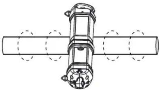
natural_image
Technical line drawing of a mechanical device with cylindrical body and flanged ends, no text or symbols presenttext_image
Diagram showing a cable or wire connection between two rectangular blocks with labeled 'C' and 'O' on each side, connected by a cable to a device.text_image
Diagram of a vertical device with numbered parts and control buttons, likely for labeling or assembly instructions.2.5 SC-600-EUR Signaalklem (optioneel)
natural_image
Line drawing of a clamp or measuring tool with handle, grip, and screwdriver (no text or symbols)3. HOOFDTOEPASSINGEN
natural_image
Technical line drawing of a mechanical component with symmetrical features and dashed circular annotations (no text or symbols)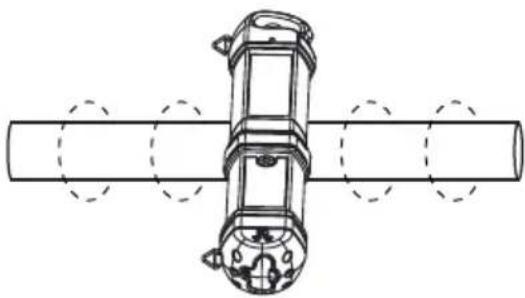
natural_image
Technical line drawing of a mechanical assembly with cylindrical components and mounting holes (no text or symbols)text_image
L N PE 3kHz 33kHz 50Hz Radio 100 0 0 0 0 0 0 0 0 0 0 0 0 0 0 0 0 0 0 0 0 0 0 0 0 0 0 0 0 0 0 0 0 0 0 0 0 0 0 0 0 0 0 0 0 0 0 0 0 0 0text_image
Diagram showing a cable or wire connection between two rectangular blocks with labeled 'C' and 'O' on the left side, connected by a cable to a device.- PRECAUTIONS AND SAFETY MEASURES......2
- KIT COMPONENTS ....4
1. PRECAUTIONS AND SAFETY MEASURES
SYMBOLE
text_image
Labeled diagram of a medical or laboratory device with numbered parts for identification.text_image
Diagram of a vertical device with numbered parts and control buttons, likely for labeling or assembly instructions.natural_image
Line drawing of a manual clamp or measuring tool with handle, clasp, and screwdriver (no text or symbols)3. GŁÓWNE ZASTOSOWANIA
natural_image
Technical line drawing of a mechanical component with symmetrical features and dashed circular annotations (no text or symbols)
natural_image
Technical line drawing of a mechanical assembly with cylindrical components and dashed circular features (no text or symbols)text_image
Diagram showing a mechanical device connected to a spring-loaded cable, with red lines indicating rotation directions.- HUVUDAPPLIKATIONER....10
text_image
Diagram of a vertical device with numbered parts and control buttons, likely for labeling or assembly instructions.2.5 SC-600-EUR Signalklämma (tillval)
natural_image
Line drawing of a mechanical clamp or measuring tool with handle, grip, and screwdriver (no text or symbols)3. HUVUDAPPLIKATIONER
natural_image
Technical line drawing of a mechanical component with symmetrical features and centerlines (no text or symbols)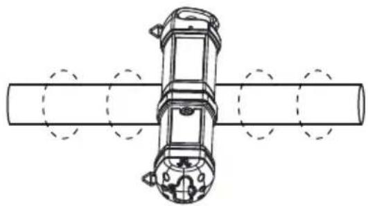
natural_image
Technical line drawing of a mechanical device with cylindrical body and flanged ends, no text or symbols presenttext_image
Diagram showing a cable or wire connection between two rectangular blocks with labeled 'C' and 'O' on the left side, connected to a mechanical clamp.Germany NR6 6JB United Kingdom The Netherlands
Puhelin: +49 (0) 7684 8009 - 0 Puhelin: +44 (0) 1603 25 6662 Puhelin: +31 (0) 40 267 51 00
beha-amprobe.de
beha-amprobe.com
beha-amprobe.com
- TEKNISET TIEDOT ....21
1. VAROTOIMET JA TURVALLISUUSTOIMENPITEET
SYMBOLIT
text_image
Technical diagram of a vertical mechanical device with numbered parts and control buttonsnatural_image
Line drawing of a clamp or measuring tool with handle, grip, and screwdriver (no text or symbols)3. PÄÄSOVELLUKSET
natural_image
Technical line drawing of a mechanical component with symmetrical features and centerlines (no text or symbols)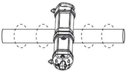
natural_image
Technical line drawing of a mechanical component with circular features, no text or symbols presenttext_image
Diagram showing a cable or wire connection between two rectangular blocks with labeled 'C' and 'O' on the left side, connected to a mechanical clamp.- ESPECIFICAÇÕES......21
Controles do receptor
Controles do transmissor
text_image
Diagram of a vertical device with numbered parts and control buttons, likely for labeling or assembly instructions.natural_image
Line drawing of a clamp or measuring tool with handle, grip, and screwdriver (no text or symbols)3. PRINCIPAIS APLICAÇÕES
natural_image
Technical line drawing of a mechanical component with symmetrical features and centerlines (no text or symbols)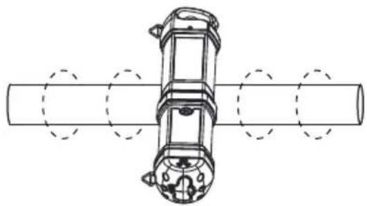
natural_image
Technical line drawing of a mechanical component with circular features, no text or symbols presenttext_image
Diagram showing a cable or wire connection between two rectangular blocks with labeled 'Q' and 'E' on the left side, connected to a device.text_image
Diagram of a vertical device with numbered parts and control buttons, likely for labeling or assembly instructions.2.5 SC-600-EUR signalklemme (valgfritt)
natural_image
Line drawing of a mechanical clamp or measuring tool with handle, grip, and screwdriver (no text or symbols)3. HOVEDSAKELIGE BRUKSOMRÅDER
natural_image
Technical line drawing of a mechanical component with symmetrical features and centerlines (no text or symbols)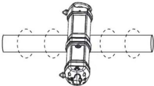
natural_image
Technical line drawing of a mechanical assembly with cylindrical components and mounting holes (no text or symbols)text_image
Diagram showing a cable or wire connection with a clamp and electrical component, labeled with 'Q' on both sides.text_image
Technical diagram of a vertical mechanical device with numbered parts and control buttons2.5 CT-600-EUR Signalklemme (ekstraudstyr)
natural_image
Line drawing of a mechanical clamp or measuring tool with handle, grip, and screwdriver (no text or symbols)3. DE VIGTIGSTE ANVENDELSESOMRÅDER
natural_image
Technical line drawing of a mechanical component with symmetrical features and centerlines (no text or symbols)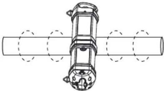
natural_image
Technical line drawing of a mechanical assembly with cylindrical components and mounting holes (no text or symbols)text_image
Diagram showing a cable or wire connection with a clamp and electrical component, labeled with 'Q' on both sides.- Catalog
- Application notes
• Product specifications - User manuals
Beha-Amprobe®
Division of Fluke Corp. (USA)
c/o Fluke Europe BV
BIC 1
5657 BX Eindhoven
The Netherlands
Tel.: +49 (0) 7684 8009 - 0