Bluehelix B S 32 K 100 - Central heating boiler FERROLI - Free user manual and instructions
Find the device manual for free Bluehelix B S 32 K 100 FERROLI in PDF.
User questions about Bluehelix B S 32 K 100 FERROLI
0 question about this device. Answer the ones you know or ask your own.
Ask a new question about this device
Download the instructions for your Central heating boiler in PDF format for free! Find your manual Bluehelix B S 32 K 100 - FERROLI and take your electronic device back in hand. On this page are published all the documents necessary for the use of your device. Bluehelix B S 32 K 100 by FERROLI.
USER MANUAL Bluehelix B S 32 K 100 FERROLI
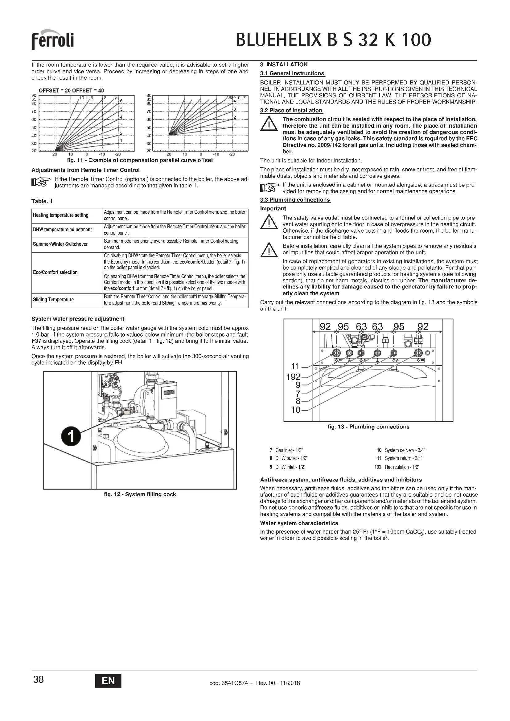
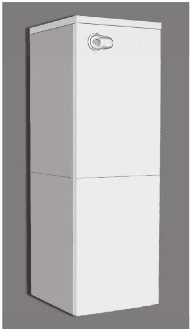
BLUEHELIX B S 32 K 100

cod. 3541G574 - Rev. 00 - 11/2018
natural_image
3D rendering of a white rectangular appliance with a handle and lid (no text or symbols visible)CE
IT - ISTRUZIONE PER L'USO L'INSTALLAZIONE E LA MANUTENZIONE
ES - INSTRUCCIONES DE USO, INSTALACIÓN Y MANTENIMIENTO
TR - KULLANMA, KURULUM VE BAKİM TALIMATLARI
EN - INSTRUCTIONS FOR USE, INSTALLATION AND MAINTENANCE
FR - INSTRUCTIONS D'UTILISATION, D'INSTALLATION ET D'ENTRETIEN
RU - РУКОВОДСТВО ПО ЭКСПЛУАТАЦИИ, МОНТАЖУ И ТЕХОБСЛУЖИВАНИЮ
UK - ІНСТРУКЦІЯ З ЕКСПЛУАТАЦІЇ, МОНТАЖУ ТА ОБСЛУГОВУВАННЯ
IT
1. AVVERTENZE GENERALI
OFFSET = 20 OFFSET = 40
line
| X | Y | |---|---| | -20 | 20 | | -15 | 30 | | -10 | 40 | | -5 | 50 | | 0 | 60 | | 5 | 70 | | 10 | 80 | | 15 | 90 | The chart displays a linearly increasing trend of the Y-axis values as the X-axis values increase. Each line corresponds to a specific numerical label (e.g., 1, 2, ..., 10). The data points are explicitly labeled on the axes.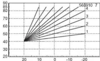
line
| X | Y (Line 1) | Y (Line 2) | Y (Line 3) | Y (Line 4) | Y (Line 5) | Y (Line 6) | Y (Line 7) | |---|---|---|---|---|---|---|---| | -20 | 40 | 40 | 40 | 40 | 40 | 40 | 40 | | -10 | 50 | 55 | 60 | 65 | 70 | 75 | 80 | | 0 | 60 | 65 | 70 | 75 | 80 | 85 | 90 | | 10 | 70 | 75 | 80 | 85 | 90 | 95 | 100 | | 20 | 80 | 85 | 90 | 95 | 100 | 105 | 110 |text_image
Technical diagram of an industrial machine with labeled component '1' pointing to a component.natural_image
Technical line drawing of a mechanical assembly with rotating components (no text or symbols)fig. 21
text_image
A C B Dfig. 22
text_image
Diagram of a car air conditioning control panel with digital display and directional arrows indicating motion or operation.text_image
Technical diagram of a device with labeled components and directional arrows indicating assembly or movement.fig. 24 - Apertura pannello frontale
Controllo periodico
text_image
Diagram of a car air conditioner control panel with labeled buttons and gaugesOFFSET = 20 OFFSET = 40

line
| X | Y | |---|---| | -20 | 20 | | -15 | 30 | | -10 | 40 | | -5 | 50 | | 0 | 60 | | 5 | 70 | | 10 | 80 | | 15 | 90 | The chart displays a series of lines labeled 1 through 10, with each line representing a separate data series. The x-axis ranges from -20 to 20, and the y-axis ranges from 20 to 90. No title or legend is present; the data points are explicitly labeled on the graph.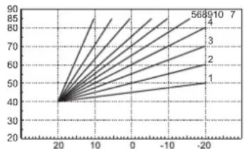
line
| X | Y | |---|---| | 20 | 40 | | -20 | 568910 | | -10 | 70 | | 0 | 85 | | 10 | 90 | | 20 | 95 |text_image
Technical diagram of a mechanical device with labeled component '1' pointing to a component.natural_image
Technical line drawing of a mechanical assembly with no visible text or symbolsfig. 21
text_image
A C B Dfig. 22
text_image
Diagram of a car air conditioner control panel with directional indicators and temperature display showing 00°Ctext_image
Technical diagram of a device interior with labeled components and directional arrows indicating assembly or movement.fig. 24 - Apertura del panel frontal
Control periódico
OFFSET = 20 OFFSET = 40
line
| X | Y | |---|---| | -20 | 20 | | -15 | 30 | | -10 | 40 | | -5 | 50 | | 0 | 60 | | 5 | 70 | | 10 | 80 | | 15 | 90 | The chart displays a linearly increasing trend of the Y-axis values as the X-axis values decrease. Each curve corresponds to a specific integer label (1 through 10). The chart is saved as a PNG file named 'chart.png'.
line
| X | Y | |---|---| | 20 | 40 | | 10 | 50 | | 0 | 60 | | -10 | 70 | | -20 | 80 | | -30 | 90 | The chart displays a single data series with multiple lines labeled 1 through 7. The x-axis ranges from -20 to 20, and the y-axis ranges from 20 to 90. No explicit title or axis labels are provided in the image.text_image
Technical diagram of an industrial machine with labeled component '1' pointing to a component.natural_image
Technical line drawing of a mechanical assembly with no visible text or symbolsşek. 21
text_image
A C B Dşek. 22
text_image
Diagram of a car air conditioning control panel with directional indicators and temperature displaytext_image
Technical diagram of a mechanical device with labeled components and directional arrows indicating assembly or movement.- Carefully read and follow the instructions contained in this instruction booklet.
- After boiler installation, inform the user regarding its operation and give him this manual, which is an integral and essential part of the product and must be kept with care for future reference.
• Installation and maintenance must be carried out by professionally qualified personnel, in compliance with the current regulations and according to the manufacturer's instructions. Do not carry out any operation on the sealed control parts. - Incorrect installation or inadequate maintenance can result in damage or injury. The Manufacturer declines any liability for damage due to errors in installation and use, or failure to follow the instructions.
- Before carrying out any cleaning or maintenance operation, disconnect the unit from the electrical power supply using the switch and/or the special cut-off devices.
- In case of a fault and/or poor operation, deactivate the unit and do not try to repair it or directly intervene. Contact professionally qualified personnel. Any repair/replacement of the products must only be carried out by qualified personnel using original replacement parts. Failure to comply with the above could affect the safety of the unit.
- This unit must only be used for its intended purpose. Any other use is deemed improper and therefore hazardous.
- The packing materials are potentially hazardous and must not be left reach of children.
- The unit must not be used by people (including children) with limited physical, sensory or mental abilities or without experience and knowledge of it, unless instructed or supervised in its use by someone responsible for their safety.
- The unit and its accessories must be appropriately disposed of, in compliance with the current regulations.
- The images given in this manual are a simplified representation of the product. In this representation there may be slight and insignificant differences with respect to the product supplied.
2. OPERATING INSTRUCTIONS
2.1 Introduction
Dear Customer,
BLUEHELIX B S 32 K 100 is a high-efficiency, low emissions sealed chamber, premix condensing heat generator with heat exchanger in steel and incorporated DHW production, using natural gas or LPG and equipped with a microprocessor control system.
The stainless steel quick storage tank incorporated in the boiler ensures plenty of domestic hot water.
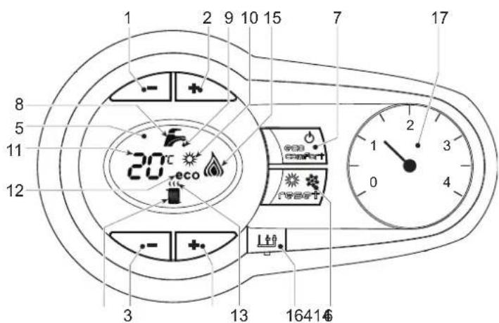
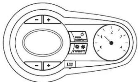
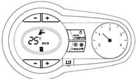
2.2 Control panel
text_image
1 2 9 10 15 7 17 8 5 11 12 20°C eco 3 13 1641€fig. 1 - Control panel
Panel - legend fig. 1
1 DHW temperature setting decrease button
2 DHW temperature setting increase button
3 Heating system temperature setting decrease button
4 Heating system temperature setting increase button
5 Display
6 "Sliding Temperature" Menu - Summer/Winter mode selection - Reset button
7 Unit On/Off - Economy/Comfort mode selection button
8 DHW symbol
9 DHW mode
10 Summer mode
11 Multifunction (flashing during exchanger protection function)
12 Eco (Economy) mode
13 Heating
14 Heating symbol
15 Burner lit and actual power level (flashing during flame protection function)
16 Service Tool connection
17 Water gauge
Indication during operation
Heating
A heating demand (generated by the Room Thermostat or Remote Timer Control) is indicated by flashing of the hot air above the radiator on the display.
The display (detail 11 - fig. 1) shows the actual heating delivery temperature and, during heating standby time, the message "d2".
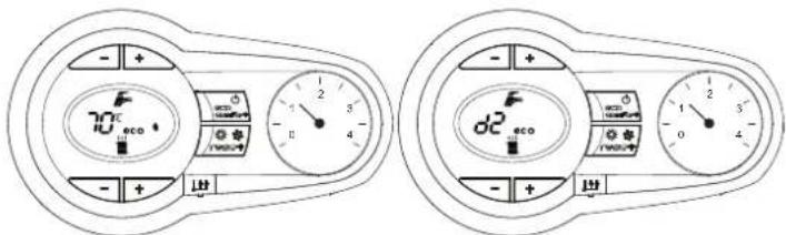
text_image
70°C eco d2 ecofig. 2
Domestic hot water (DHW)
A DHW demand (generated by drawing hot water) is indicated by flashing of the hot water under the tap on the display.
The display (detail 11 - fig. 1) displays the actual DHW outlet temperature and, during DHW standby time, the message "d1".
within the
text_image
SS d d'fig. 3
Fault
In case of a fault (see cap. 4.4) the display shows the fault code (detail 11 - fig. 1) and, during safety standby times, the messages "d3" and "d4".
2.3 Connection to the power supply, switching on and off
Boiler not electrically powered
text_image
- + + - + + L11fig. 4 - Boiler not electrically powered

To avoid damage caused by freezing during long idle periods in winter, it is advisable to drain all the water from the boiler.
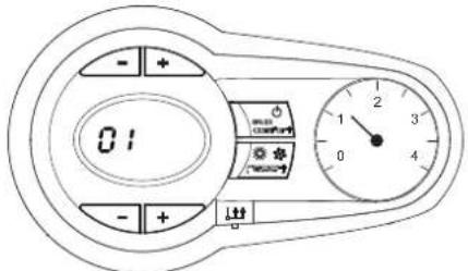
Boiler electrically powered
Switch on the power to the boiler.
text_image
01 - + + - + ↓fig. 5 - Switching on / Software version
text_image
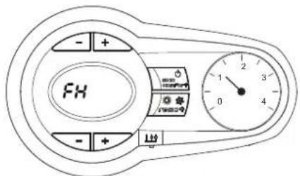
- + FH - + 0 4 1 2 3 0fig. 6 - Venting cycle
• During the first 5 seconds the display also shows the card software version
- For the following 300 seconds the display shows FH which identifies the heating system air venting cycle.
- Open the gas cock ahead of the boiler
- When the message FH disappears, the boiler is ready to operate whenever domestic hot water is drawn or in case of a room thermostat demand
Switching the boiler off and on
Press the on/off button (detail 7 - fig. 1) for 5 seconds.
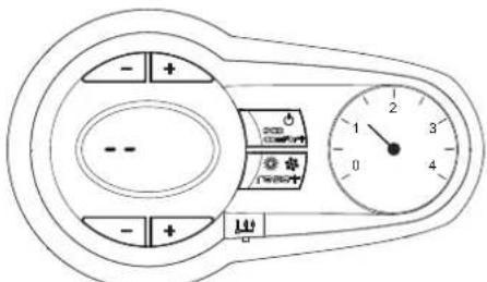
fig. 7 - Switching the boiler off
When the boiler is switched off, the electronic board is still powered. Domestic hot water and heating are disabled The antifreeze system remains activated. To switch the boiler on, press the on/off button (detail 7 - fig. 1) again for 5 seconds.
text_image
25°C ecofig. 8
The boiler will be immediately ready to operate whenever domestic hot water is drawn or in case of a room thermostat demand.

The antifreeze system does not work when the power and/or gas to the unit are turned off. To avoid damage caused by freezing during long shutdowns in winter, it is advisable to drain all water from the boiler, the DHW circuit and the heating system water; or drain just the DHW circuit and add a suitable antifreeze to the heating system, as prescribed in sec. 3.3.
2.4 Adjustments
Summer/Winter Switchover
Press the summer/winter button (detail 6 - fig. 1) for 2 seconds.
The display activates the Summer symbol (detail 10 - fig. 1): the boiler will only deliver domestic hot water. The antifreeze system remains activated.
To deactivate the Summer mode, press the summer/winter button (detail 6 - fig. 1) again for 2 seconds.
Heating temperature adjustment
Use the heating buttons (details 3 and 4 - fig. 1) to adjust the temperature from a min. of 20°C to a max. of 80°C.
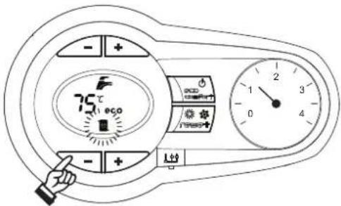
text_image
- + 75°C 0 + + - + 出fig. 9
DHW temperature adjustment
Use the DHW buttons (details 1 and 2 - fig. 1) to adjust the temperature from a minimum of 10^ C to a maximum of 65^ C.
automatically
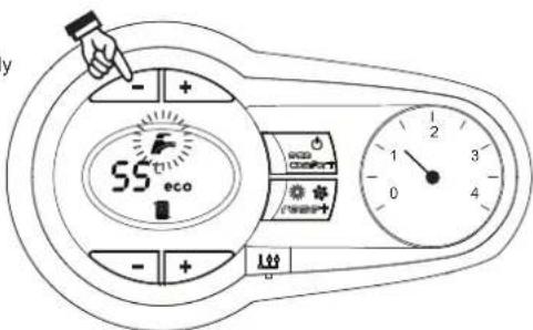
text_image
y - + 55° eco eco Comfort + - + 0 4 1 2 3 4fig. 10
Room temperature adjustment (with optional room thermostat)
Using the room thermostat, set the temperature required in the rooms. If the room thermostat is not installed, the boiler will keep the system at the set system delivery setpoint temperature.
Room temperature adjustment (with optional remote timer control)
Using the remote timer control, set the required temperature in the rooms. The boiler will adjust the system water according to the required room temperature. For operation with remote timer control, please refer to the relevant instruction manual.
Hot water tank exclusion (economy)
Hot water tank temperature maintaining/heating can be excluded by the user. If excluded, domestic hot water will not be delivered.
The hot water tank can be deactivated by the user (ECO mode) by pressing the ECO/COMFORT button (detail 7 - fig. 1). In ECO mode the display activates the ECO symbol (detail 12 - fig. 1). To activate COMFORT mode, press the ECO/COMFORT button (detail 7 - fig. 1) again.
Sliding Temperature
When the optional external probe is installed, the boiler adjustment system works with "Sliding Temperature". In this mode, the temperature of the heating system is controlled according to the outside weather conditions, to ensure high comfort and energy saving throughout the year. In particular, the system delivery temperature is decreased as the outside temperature increases, according to a specific "compensation curve".
With Sliding Temperature adjustment, the temperature set with the heating buttons (detail 3 - fig. 1) becomes the maximum system delivery temperature. It is advisable to set a maximum value to allow system adjustment throughout its useful operating range.
The boiler must be adjusted at the time of installation by qualified personnel. Possible adjustments can in any case be made by the user to improve comfort.
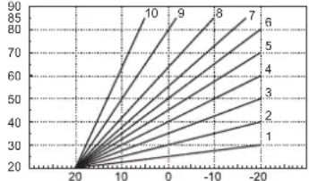
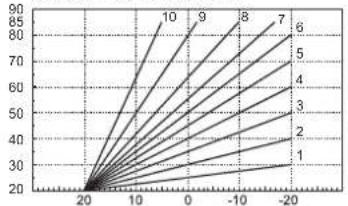
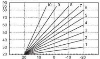
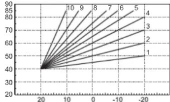
Compensation curve and curve offset
Press the reset button (detail 6 - fig. 1) for 5 seconds to access the "Sliding temperature" menu; the display shows "CU" flashing.
Use the DHW buttons (detail 1 - fig. 1) to adjust the curve from 1 to 10 according to the characteristic. By setting the curve to 0, sliding temperature adjustment is disabled.
Press the heating buttons (detail 3 - fig. 1) to access parallel curve offset; the display shows "OF" flashing. Use the DHW buttons (detail 1 - fig. 1) to adjust the parallel curve offset according to the characteristic (fig. 11).
Press the reset button (detail 6 - fig. 1) again for 5 seconds to exit the "Sliding Temperature" menu.
If the room temperature is lower than the required value, it is advisable to set a higher order curve and vice versa. Proceed by increasing or decreasing in steps of one and check the result in the room.
OFFSET = 20 OFFSET = 40
line
| X | Y | |---|---| | -20 | 20 | | -15 | 30 | | -10 | 40 | | -5 | 50 | | 0 | 60 | | 5 | 70 | | 10 | 80 | | 15 | 90 | The chart displays a single data series with multiple lines labeled 1 through 10. The x-axis ranges from -20 to 20, and the y-axis ranges from 20 to 90. No title or legend is present; the data points are explicitly labeled on the graph.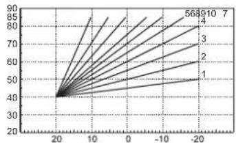
line
| X | Y | |---|---| | 20 | 40 | | 10 | 50 | | 0 | 60 | | -10 | 70 | | -20 | 80 | | -30 | 90 | The chart displays a series of lines labeled 1 through 7, suggesting a linear relationship or transformation between the variables. The x-axis ranges from -20 to 20, and the y-axis ranges from 20 to 90. No explicit title or axis labels are provided in the image.fig. 11 - Example of compensation parallel curve offset
Adjustments from Remote Timer Control

If the Remote Timer Control (optional) is connected to the boiler, the above adjustments are managed according to that given in table 1.
Table. 1
| Heating temperature setting | Adjustment can be made from the Remote Timer Control menu and the boiler control panel. |
| DHW temperature adjustment | Adjustment can be made from the Remote Timer Control menu and the boiler control panel. |
| Summer/Winter Switchover | Summer mode has priority over a possible Remote Timer Control heating demand. |
| Eco/Comfort selection | On disabling DHW from the Remote Timer Control menu, the boiler selects the Economy mode. In this condition, the eco/comfort button (detail 7 - fig. 1) on the boiler panel is disabled. |
| On enabling DHW from the Remote Timer Control menu, the boiler selects the Comfort mode. In this condition it is possible select one of the two modes with the eco/comfort button (detail 7 - fig. 1) on the boiler panel. | |
| Sliding Temperature | Both the Remote Timer Control and the boiler card manage Sliding Temperature adjustment: the boiler card Sliding Temperature has priority. |
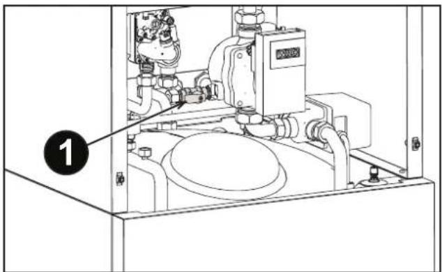
System water pressure adjustment
The filling pressure read on the boiler water gauge with the system cold must be approx 1.0 bar. If the system pressure falls to values below minimum, the boiler stops and fault F37 is displayed. Operate the filling cock (detail 1 - fig. 12) and bring it to the initial value. Always turn it off it afterwards.
Once the system pressure is restored, the boiler will activate the 300-second air venting cycle indicated on the display by FH.
text_image
Technical diagram of an industrial machine with labeled component 1, showing internal components and piping layout.fig. 12 - System filling cock
3. INSTALLATION
3.1 General Instructions
BOILER INSTALLATION MUST ONLY BE PERFORMED BY QUALIFIED PERSONNEL, IN ACCORDANCE WITH ALL THE INSTRUCTIONS GIVEN IN THIS TECHNICAL MANUAL, THE PROVISIONS OF CURRENT LAW, THE PRESCRIPTIONS OF NATIONAL AND LOCAL STANDARDS AND THE RULES OF PROPER WORKMANSHIP.
3.2 Place of installation

The combustion circuit is sealed with respect to the place of installation, therefore the unit can be installed in any room. The place of installation must be adequately ventilated to avoid the creation of dangerous conditions in case of any gas leaks. This safety standard is required by the EEC Directive no. 2009/142 for all gas units, including those with sealed chamber.
The unit is suitable for indoor installation.
The place of installation must be dry, not exposed to rain, snow or frost, and free of flammable dusts, objects and materials and corrosive gases.

If the unit is enclosed in a cabinet or mounted alongside, a space must be provided for removing the casing and for normal maintenance operations.
3.3 Plumbing connections
Important

The safety valve outlet must be connected to a funnel or collection pipe to prevent water spurting onto the floor in case of overpressure in the heating circuit. Otherwise, if the discharge valve cuts in and floods the room, the boiler manufacturer cannot be held liable.

Before installation, carefully clean all the system pipes to remove any residuals or impurities that could affect proper operation of the unit.
In case of replacement of generators in existing installations, the system must be completely emptied and cleaned of any sludge and pollutants. For that purpose only use suitable guaranteed products for heating systems (see following section), that do not harm metals, plastics or rubber. The manufacturer declines any liability for damage caused to the generator by failure to properly clean the system.
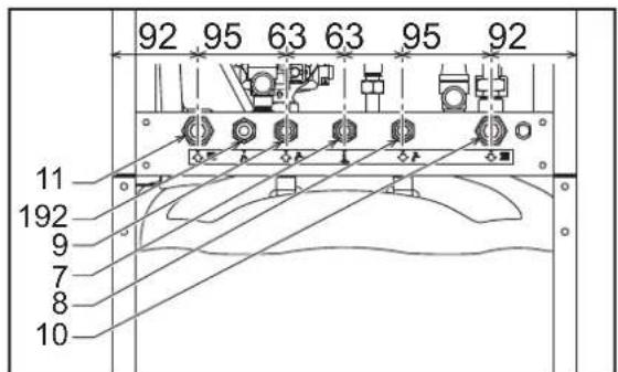
Carry out the relevant connections according to the diagram in fig. 13 and the symbols on the unit.
text_image
92 95 63 63 95 92 11 192 9 7 8 10fig. 13 - Plumbing connections
Antifreeze system, antifreeze fluids, additives and inhibitors
When necessary, antifreeze fluids, additives and inhibitors can be used only if the manufacturer of such fluids or additives guarantees that they are suitable and do not cause damage to the exchanger or other components and/or materials of the boiler and system. Do not use generic antifreeze fluids, additives or inhibitors that are not specific for use in heating systems and compatible with the materials of the boiler and system.
Water system characteristics
In the presence of water harder than 25^ Fr ( 1^ F = 10ppm CaCO _3 ), use suitably treated water in order to avoid possible scaling in the boiler.
3.4 Gas connection

Before making the connection, ensure that the unit is arranged for operation with the type of fuel available.
The gas must be connected to the relevant connection (see fig. 13) in conformity with the current standards, using a rigid metal pipe or a continuous surface flexible s/steel tube and installing a gas cock between the system and boiler. Make sure all the gas connections are tight.
3.5 Electrical connections

The unit must be connected to an efficient earthing system in accordance with the current safety standards. Have the efficiency and suitability of the earthing system checked by professionally qualified personnel; the Manufacturer declines any liability for damage caused by failure to earth the system.
The boiler is prewired and provided with a "Y" type cable (without plug) for connection to the electric line. The connection to the mains must be permanent and have a bipolar switch with contact gap of at least 3 mm, interposing fuses of max. 3A between the boiler and the line. Make sure to respect the polarities (LINE: brown wire / NEUTRAL: blue wire / EARTH: yellow-green wire) in the connections to the electric line.

The power cable must not be replaced by the user. If the cable gets damaged, switch off the unit and have it changed by professionally qualified personnel. If replacing the power cable, only use "HAR H05 VV-F" 3x0.75 mm2 cable with max. external diameter 8 mm.
Room thermostat (optional)

IMPORTANT: THE ROOM THERMOSTAT MUST HAVE VOLTAGE-FREE CONTACTS. CONNECTING 230V TO THE ROOM THERMOSTAT TERMINALS WILL PERMANENTLY DAMAGE THE PCB.
When connecting a time control or timer, do not take the power supply for such devices from their cutoff contacts. Their power supply must be taken with a direct connection from the mains or with batteries, depending on the type of device.
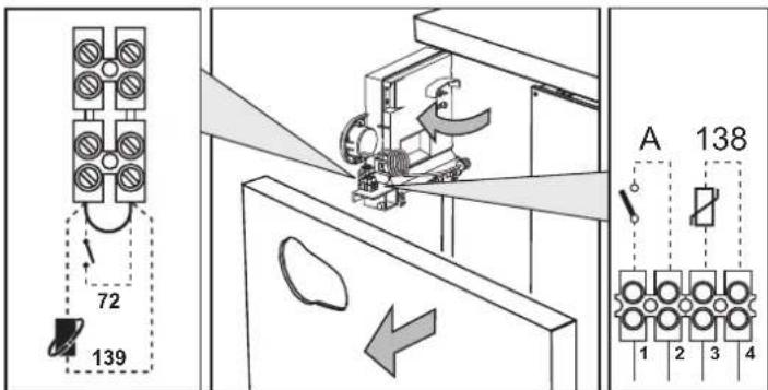
Accessing the electrical terminal block
The electrical terminal block (fig. 14) can be accessed after removing the front panel ( ^ 'Opening the front panel' on page 41 ^ ). The arrangement of the terminals for the various connections is also given in the wiring diagram in fig. 30.
text_image
72 139 A 138 6 1 2 3 4fig. 14 - Accessing the terminal block
3.6 Fume ducts
Important
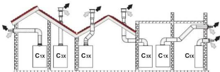
The unit is a "C type" with sealed chamber and forced draught; the air inlet and fume outlet must be connected to one of the following extraction/suction systems. Before installation, check and carefully follow the instructions. Also, comply with the provisions on the positioning of wall and/or roof terminals and the minimum distances from windows, walls, ventilation openings, etc.
Connection with coaxial pipes
flowchart
graph TD
    A["C1x"] --> B["C3x"]
    B --> C["C3x"]
    C --> D["C3x"]
    D --> E["C1x"]
    E --> F["C1x"]
    style A fill:#f9f,stroke:#333
    style B fill:#f9f,stroke:#333
    style C fill:#f9f,stroke:#333
    style D fill:#f9f,stroke:#333
    style E fill:#f9f,stroke:#333
    style F fill:#f9f,stroke:#333
fig. 15 - Examples of connection with coaxial pipes (≡ Air / = R→es)
Table. 2 - Typology
| Type Description | |
| C1X | Wall horizontal exhaust and inlet |
| C3X | Roof vertical exhaust and inlet |
For coaxial connection, fit the unit with one of the following starting accessories. Any horizontal sections of the fume exhaust must be kept sloping slightly towards the boiler, to prevent possible condensate from flowing back towards the outside and causing dripping.
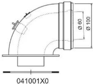
text_image
Ø 60 Ø 100 041001X0fig. 16 Starting accessories for coaxial ducts
Table. 3 - Max. length of coaxial pipes
| Coaxial 60/100 Coaxial 80/125 | ||
| Max. permissible length (horizontal) 7 m | 28 m | |
| Max. permissible length (vertical) 8 m | ||
| Reduction factor 90° bend 1 m 0.5 m | ||
| Reduction factor 45° bend 0.5 m 0.25 m | ||
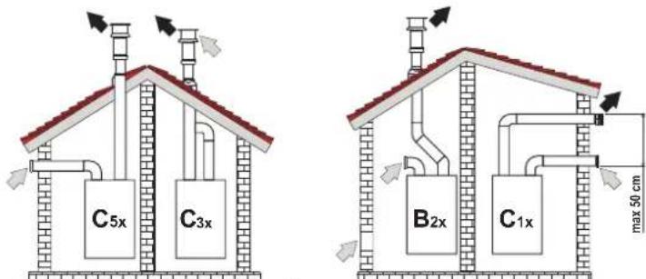
Connection with separate pipes
text_image
C5x C3x B2x C1x max 50 cmfig. 17 - Examples of connection with separate pipes ( = Air / = Fores)
Table. 4 - Typology
| Type | Description |
| C1X | Wall horizontal exhaust and intake. The inlet/outlet terminals must be concentric or close enough to be undergo similar wind conditions (within 50 cm) |
| C3X | Roof vertical exhaust and intake. Inlet/outlet terminals like for C12 |
| C5X | Wall or roof exhaust and intake separate or in any case in areas with different pressures. The exhaust and intake must not be positioned on opposite walls. |
| C6X | Intake and exhaust with separately certified pipes (EN 1856/1) |
| B2X | Intake from installation room and wall or roof exhaustIMPORTANT - THE ROOM MUST BE PROVIDED WITH APPROPRIATE VENTILATION |
For the connection of separate ducts, fit the unit with the following starting accessory (Air = - Fumes = )
041065X0
text_image
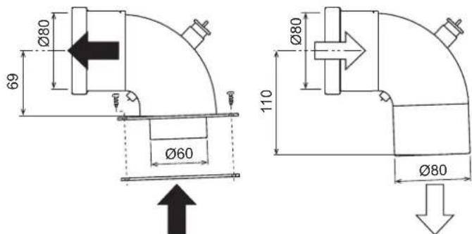
Ø80 69 Ø60 110 Ø80 Ø80fig. 18 - Starting accessory for separate ducts
Before installation, make sure the maximum permissible length has not been exceeded, by means of a simple calculation:
- Completely establish the layout of the system of split flues, including accessories and outlet terminals.
- Consult the table 6 and identify the losses in m eq (equivalent metres) of every component, according to the installation position.
- Check that the sum total of losses is less than or equal to the maximum permissible length in table 5.
Table. 5 - Maximum length of separate ducts
| Max. permissible length | 55 m_eq |
Table. 6 - Accessories
| Losses in m_eq | ||||||
| Air inlet | Fume exhaust | |||||
| Vertical Horizontal | ||||||
| ∅ 80 | PIPE | 1 m M/F 1KWMA83W 1.0 1.6 2.0 | ||||
| BEND | 45° M/F 1KWMA65W 1.2 | 1.8 | ||||
| 90° M/F 1KWMA01W 1.5 | 2.0 | |||||
| PIPE SECTION | with test point | 1KWMA70W 0.3 | 0.3 | |||
| TERMINAL | air, wall | 1KWMA85A 2.0 | - | |||
| fumes, wall with antiwind | 1KWMA86A | - | 5.0 | |||
| FLUE | Split air/fumes 80/60 | 010027X0 | - | 12.0 | ||
| Fume outlet only ∅80 010026X0 + 1KWMA86U | - | 4.0 | ||||
| ∅ 60 | PIPE | 1 m M/F 1KWMA89W | 6.0 | |||
| BEND | 90° M/F 1KWMA88W | 4.5 | ||||
| REDUCTION | 80/60 | 041050X0 | 5.0 | |||
| TERMINAL | fumes, wall with antiwind | 1KWMA90A | 7.0 | |||
 | ATTENTION: CONSIDER THE HIGH PRESSURE LOSSES OF ∅60 ACCESSORIES; USE THEM ONLY IF NECESSARY AND AT THE LAST FUME EXHAUST SECTION. | |||||
Connection to collective flues
text_image
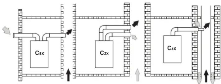
C8x C2x C4xfig. 19 - Examples of connection to flues (≡ Air / = F ≦ es)
Table. 7 - Typology
| Type | Description |
| C2X | Intake and exhaust in common flue (intake and exhaust in same flue) |
| C4X | Intake and exhaust in common and separate flues, but undergoing similar wind conditions |
| C8X | Exhaust in single or common flue and wall intake |
| B3X | Intake from installation room by means of concentric duct (that encloses the exhaust) and exhaust in common flue with natural draughtIMPORTANT - THE ROOM MUST BE PROVIDED WITH APPROPRIATE VENTILATION |
If the boiler is to be connected BLUEHELIX B S 32 K 100 to a collective flue or a single flue with natural draught, the flue or chimney must be expressly designed by professionally qualified technical personnel in conformity with the current regulations and be suitable for sealed chamber units equipped with fan.
3.7 Condensate drain connection
The boiler has an internal trap for draining condensate. Fit the inspection coupling A and the hose B, pressing it in for approx. 3 cm and securing it with a clamp. Fill the trap with approx. 0.5 L of water and connect the hose to the disposal system.

ATTENTION: The unit must never be operated with the trap empty!
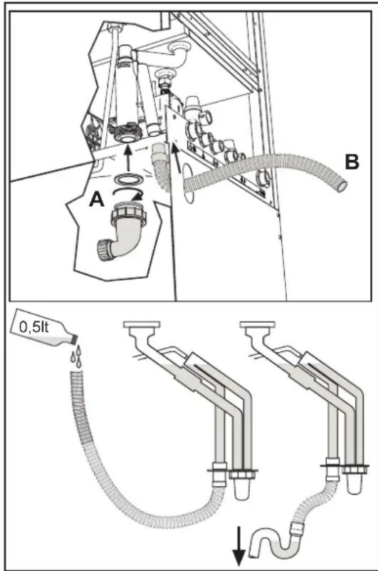
text_image
A B 0,5ltfig. 20 - Condensate outlet connection
4. SERVICE AND MAINTENANCE
4.1 Adjustments
Gas conversion
The unit can operate on Natural Gas or LPG and is factory-set for use with one of these two gases, as clearly shown on the packing and on the data plate. Whenever a different gas to that for which the unit is arranged has to be used, a conversion kit will be required, proceeding as follows:
- Disconnect the boiler power supply and close the gas cock.
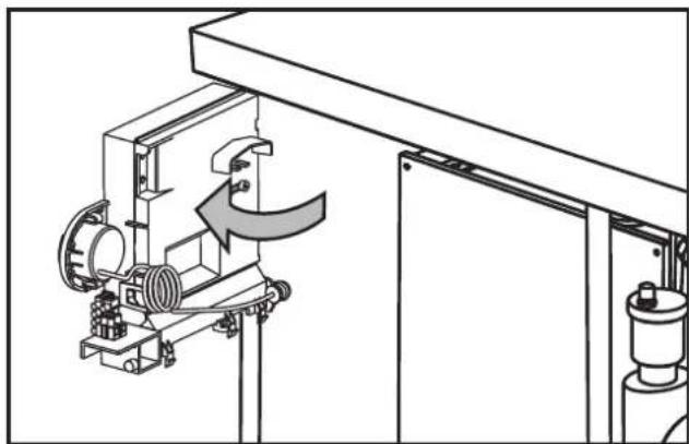
- Remove the front panel (see fig. 24).
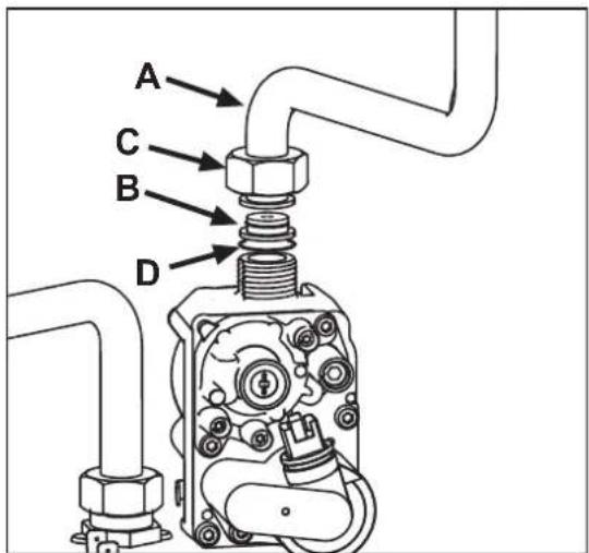
- Undo the screw and rotate the control panel (see fig. 21).
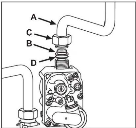
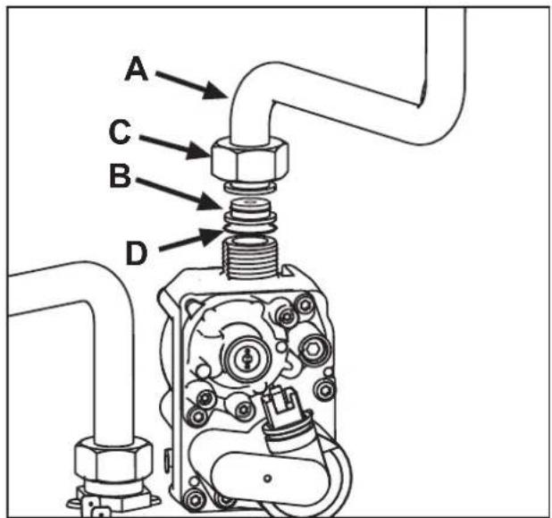
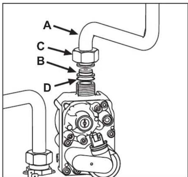
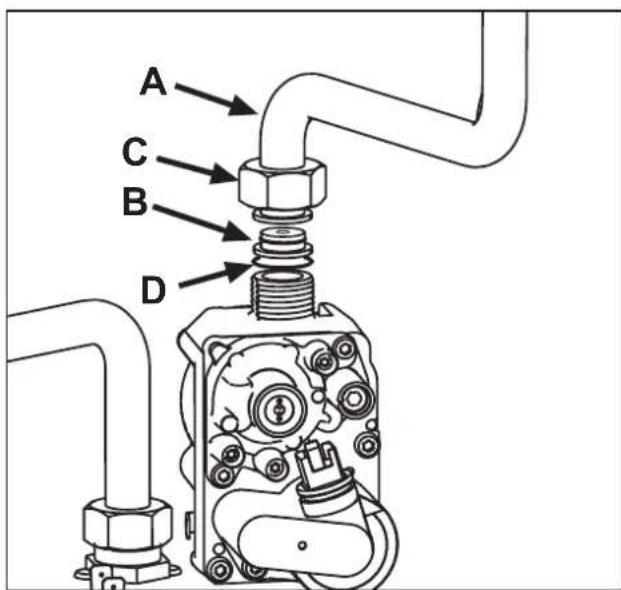
- Unscrew ring C and remove gas pipe A from the gas valve (see fig. 22).
- Replace nozzle B inserted in the gas pipe with that contained in the conversion kit, interposing seal D (see fig. 22).
- Refit gas pipe A and check the tightness of the connection.
- Apply the label, contained in the conversion kit, near the data plate.
- Refit the front panel.
- Switch the boiler power on and open the gas cock.
-
Modify the parameter for the type of gas:
-
put the boiler in standby mode
- press the DHW buttons (details 1 and 2 - fig. 1) for 10 seconds: the display shows "b01" flashing.
- press the DHW buttons (details 1 or 2 - fig. 1) to set parameter 00 (for operation with natural gas) or 01 (for operation with LPG).
- press the heating + button (detail 4 - fig. 1) until "b04" flashes on the display.
- press the DHW buttons (details 1 or 2 - fig. 1) to set parameter 210 (for operation with natural gas) or 190 (for operation with LPG).
- press the heating + button (detail 4 - fig. 1) until "b05" flashes on the display
-
press the DHW buttons (details 1 or 2 - fig. 1) to set parameter 185 (for operation with natural gas) or 175 (for operation with LPG).
• press the DHW buttons (details 1 and 2 - fig. 1) for 10 seconds.
• the boiler will return to standby mode -
Using a combustion analyser connected to the boiler fume outlet, check that the CO_2 content in the fumes, with the boiler operating at max. and min. output, matches that given in the technical data table for the corresponding type of gas.
natural_image
Technical line drawing of a mechanical assembly with no visible text or symbolsfig. 21
text_image
A C B Dfig. 22
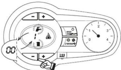
TEST mode activation
Press the heating buttons (details 3 and 4 - fig. 1) together for 5 seconds to activate the TEST mode. The boiler lights at the maximum heating power set as described in the following section.
The heating and DHW symbols (fig. 23) flash on the display; the heating power will appear alongside.
text_image
Diagram of a car air conditioner control panel with indicator lights, alarm clock, and temperature readingfig. 23 - TEST mode (heating power = 100%)
Press the heating buttons (details 3 and 4 - fig. 1) to increase or decrease the power (Min.=0%, Max.=100%).
By pressing the DHW “-” button (detail 1 - fig. 1), boiler output is immediately adjusted to min. (0%). By pressing the DHW “+” button (detail 2 - fig. 1), boiler output is immediately adjusted to max. (100%).
If the TEST mode is activated and enough hot water is drawn to activate the DHW mode, the boiler remains in TEST mode but the 3-way valve goes to DHW.
To deactivate the TEST mode, press the heating buttons (details 3 and 4 - fig. 1) together for 5 seconds.
The TEST mode is automatically deactivated in any case after 15 minutes or on stopping of hot water drawing (if enough hot water has been drawn to activate the DHW mode).
Heating power adjustment
To adjust the heating power, switch the boiler to TEST mode (see sec. 4.1). Press the heating buttons (details 3 and 4 - fig. 1) to increase or decrease the power (min. = 00 - max. = 100). Press the RESET button within 5 seconds and the max. power will remain that just set. Exit TEST mode (see sec. 4.1).
4.2 Startup
Before lighting the boiler
- Check the seal of the gas system.
- Check correct prefilling of the expansion tank.
- Fill the water system and make sure all air contained in the boiler and the system has been vented.
• Make sure there are no water leaks in the system, DHW circuits, connections or boiler. - Check correct connection of the electrical system and efficiency of the earthing system.
• Make sure the gas pressure for heating is that required.
• Make sure there are no flammable liquids or materials in the immediate vicinity of the boiler
Checks during operation
- Switch the unit on.
- Check the tightness of the fuel circuit and water systems.
- Check the efficiency of the flue and air/fume ducts while the boiler is working.
- Check the correct tightness and efficiency of the condensate removal system and trap.
• Make sure the water is circulating properly between the boiler and systems.
• Make sure the gas valve modulates correctly in heating and domestic hot water production. - Check proper lighting of the boiler by turning it on and off several times with the room thermostat or remote control.
• Make sure the fuel consumption indicated on the meter matches that given in the technical data table on cap. 5. - Make sure that with no heating demand the burner correctly lights on opening a hot water tap. Check that the heating circulating pump stops on opening a hot water tap during heating operation and there is a regular production of hot water.
- Check correct programming of the parameters and carry out any required customisation (compensation curve, power, temperatures, etc.).
4.3 Maintenance
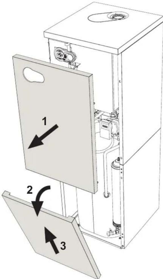
Opening the front panel
To open the boiler casing pull the panel outwards and release it (see fig. 24).

Before carrying out any operation inside the boiler, disconnect the power and close the gas cock upstream
text_image
Technical diagram of a device interior with labeled components and directional arrows indicating assembly or movement.fig. 24 - Front panel opening
Periodical check
To ensure proper operation of the unit over time, have qualified personnel carry out a yearly inspection, providing for the following checks:
- The control and safety devices (gas valve, flow meter, thermostats, etc.) must function correctly
• The fume exhaust circuit must be perfectly efficient
• The sealed chamber must be tight
• The air-fume end piece and ducts must be free of obstructions and leaks - The burner and exchanger must be clean and free of deposits For possible cleaning do not use chemical products or wire brushes
• The electrode must be properly positioned and free of scale
• The gas and water systems must be tight. - The water pressure in the cold water system must be about 1 bar; otherwise, bring it to that value
• The circulating pump must not be blocked.
• The expansion tank must be filled.
• The gas flow and pressure must correspond to that given in the respective tables - The condensate evacuation system must be efficient with no leakage or obstructions
• The trap must be full of water.
4.4 Troubleshooting
Diagnostics
In case of operation faults or problems, the display flashes and the fault identification code appears.
There are faults that cause permanent shutdown (marked with the letter "A"): to restore operation just press the reset button (detail 6 - fig. 1) for 1 second or RESET on the optional remote timer control if installed; if the boiler fails to start, it is necessary to firstly eliminate the fault.
Faults marked with the letter "F" cause temporary shutdowns that are automatically reset as soon as the value returns within the boiler's normal working range.
Table of faults
Table. 8 - List of faults
| Fault code | Fault Possible cause Cure | ||
| A01 | No burner ignition | No gas | Check the regular gas flow to the boiler and that the air has been eliminated from the pipes |
| Ignition/detection electrode fault | Check the wiring of the electrode and that it is correctly positioned and free of any deposits | ||
| Faulty gas valve | Check the gas valve and replace it if necessary | ||
| Insufficient gas supply pressure Check | the gas supply pressure | ||
| Trap blocked | Check the trap and clean it if necessary | ||
| A02 | Flame present signal with burner off | Electrode fault Check the ionisation electrode wiring | |
| Card fault Check the card | |||
| A03 | Overtemperature protection activation | Heating sensor damaged | Check the correct positioning and operation of the heating sensor |
| No water circulation in the system Check the circulating pump | |||
| Air in the system Vent the system | |||
| A04 | Fume extraction duct safety device activation | Fault F07 generated 3 times in the last 24 hours | See fault F07 |
| A05 | Fan protection activated | Fault F15 generated for 1 hour (consecutive) | See fault F15 |
| A06 | No flame after ignition stage (6 times in 4 minutes) | Ionisation electrode fault Check the position of the ionisation electrode and replace it if necessary | |
| Flame unstable | Check the burner | ||
| Gas valve Offset fault | Check the Offset adjustment at minimum power | ||
| air/fume ducts obstructed | Remove the obstruction from the flue, fume extraction ducts and air inlet and terminals | ||
| Trap blocked | Check the trap and clean it if necessary | ||
| F07 | High fume temperature | The fume probe detects an excessive temperature | Check the exchanger |
| F10 | Delivery sensor 1 fault | Sensor damaged | Check the wiring or replace the sensor |
| Wiring shorted | |||
| Wiring disconnected | |||
| F11 | Return sensor fault | Sensor damaged | Check the wiring or replace the sensor |
| Wiring shorted | |||
| Wiring disconnected | |||
| F12 | DHW sensor fault | Sensor damaged | Check the wiring or replace the sensor |
| Wiring shorted | |||
| Wiring disconnected | |||
| F13 | Fume probe fault | Probe damaged | Check the wiring or replace the fume probe |
| Wiring shorted | |||
| Wiring disconnected | |||
| Fault code | Fault | Possible cause Cure | |
| F14 | Delivery sensor 2 fault | Sensor damaged | Check the wiring or replace the sensor |
| Wiring shorted | |||
| Wiring disconnected | |||
| F15 | Fan fault | No 230V power supply | Check the 3-pin connector wiring |
| Tachometric signal interrupted | Check the 5-pin connector wiring | ||
| Fan damaged | Check the fan | ||
| F34 | Supply voltage under 170V | Electric mains trouble | Check the electrical system |
| F35 | Faulty mains frequency | Electric mains trouble | Check the electrical system |
| F37 | Incorrect system water pressure | Pressure too low | Fill the system |
| Water pressure switch damaged or not connected | Check the sensor | ||
| F39 | External probe fault | Probe damaged or wiring shorted | Check the wiring or replace the sensor |
| Probe disconnected after activating the sliding temperature | Reconnect the external probe or disable the sliding temperature | ||
| A41A44 | Sensor positioning | Heating sensor detached from pipe | Check the correct positioning and operation of the heating sensor |
| A42 | Heating sensor fault Sensor | Sensor damaged Replace the sensor | |
| F43 | Exchanger protection activation. | No system H_2O circulation | Check the circulating pump |
| Air in the system Vent the system | |||
| F52 | Heating sensor fault Sensor | Sensor damaged Replace the sensor | |
| A61 | Controller ABM03D fault | Controller ABM03D internal error | Check the earth connection and replace the controller if necessary. |
| A62 | No communication between controller and gas valve | Controller not connected | Connect the controller to the gas valve |
| Valve damaged | Replace the valve | ||
| A63F64A65F66 | Controller ABM03D fault | Controller ABM03D internal error | Check the earth connection and replace the controller if necessary. |
| A23A24F20F21A26F40F47 | Card parameter fault | Wrong card parameter setting | Check the card parameter and modify it if necessary. |
5. TECHNICAL DATA AND CHARACTERISTICS
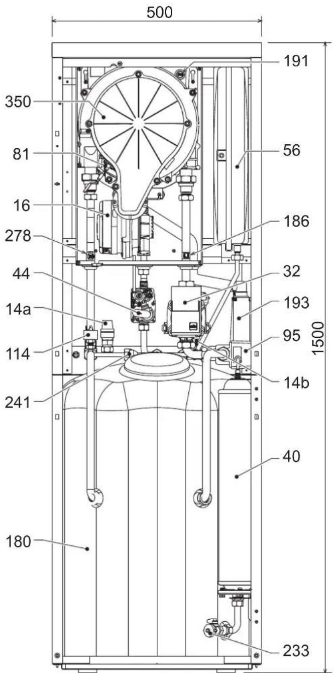
Table. 9 - Key of figures cap. 5
| 7 | Gas inlet | 114 | Water pressure switch |
| 8 | Domestic hot water outlet | 138 | External probe (optional) |
| 9 | Cold water inlet | 139 | Remote timer control (optional) |
| 10 | System delivery | 154 | Condensate drain pipe |
| 11 | System return | 180 | Hot water tank |
| 4a | DHW safety valve | 186 | Return sensor |
| 4b | System safety valve | 191 | Fume temperature sensor |
| 16 | Fan | 192 | Recirculation |
| 32 | Heating circulating pump | 193 | Trap |
| 36 | Automatic air vent | 233 | Hot water tank drain cock |
| 40 | DHW expansion tank | 241 | Automatic bypass |
| 44 | Gas valve | 243 | Hot water tank temperature sensor |
| 56 | Expansion tank | 256 | Modulating heating circulating pump signal |
| 72 | Room thermostat (not supplied) | 278 | Double sensor (Safety + Heating) |
| 74 | System filling cock | 350 | Fan/Burner assembly |
| 81 | Ionisation/ignition electrode | A | ON/OFF switch (configurable) |
| 95 | Diverter valve |
5.1 General view and main components
text_image
500 191 350 81 16 278 44 14a 114 241 180 56 186 32 193 95 1500 14b 40 233fig. 25 - Front view
text_image
9 192 74 11 785 7 8 10 92 50 45 63 63 95 92 fig. 26 - Rear view
text_image
111929810 7 12385 535 170 86 fig. 27 - Top view (AIR INLET = /FUME OUTLET = )5.2 Water circuit
flowchart
graph TD
    A["114"] --> B["278"]
    B --> C["193"]
    C --> D["154"]
    D --> E["10"]
    E --> F["8"]
    F --> G["14b"]
    G --> H["1929"]
    H --> I["14a"]
    I --> J["74"]
    J --> K["11"]
    K --> L["32"]
    L --> M["36"]
    M --> N["56"]
    N --> O["186"]
    O --> P["40"]
    P --> Q["233"]
    Q --> R["180"]
    R --> S["241"]
    S --> T["14b"]
    T --> U["10"]
    U --> V["1929"]
    V --> W["11"]
    W --> X["32"]
    X --> Y["95"]
5.3 Diagrams
Circulating pump head / pressure losses
line
| Q [l/h] | H [m H₂O] | | ------- | --------- | | 0.500 | 0 | | 1.000 | 1 | | 1.500 | 2 | | 2.000 | 3 | | 2.500 | 4 | | 3.000 | 5 | | 3.500 | 6 | | 4.000 | 7 |fig. 29 - Circulating pump head / Pressure losses BLUEHELIX B S 32 K 100
A = Boiler pressure losses - B = Circulating pump min. speed - C = Circulating pump max. speed
5.4 Technical data table
The column on the right gives the abbreviation used on the technical data plate.
| Data Unit BLUEHELIX B S 32 K 100 | |||
| Max. heating capacity kW 29.5 (Q) | |||
| Min. heating capacity kW 6.7 | (Q) | ||
| Max. Heat Output in heating (80/60°C) | kW 28.9 | (P) | |
| Min. Heat Output in heating (80/60°C) kW | 6.6 | (P) | |
| Max. Heat Output in heating (50/30°C) | kW 31.3 | ||
| Min. Heat Output in heating (50/30°C) kW | 7.2 | ||
| Max. heating capacity in hot water production | kW 32.0 | ||
| Min. heating capacity in hot water production | kW | 6.7 | |
| Max. Heat Output in hot water production | kW 31.4 | ||
| Min. Heat Output in hot water production | kW | 6.6 | |
| Efficiency Pmax (80-60°C) | % 38.1 | ||
| Efficiency Pmin (80-60°C) | % 37.8 | ||
| Efficiency Pmax (50-30°C) | % | 106.1 | |
| Efficiency Pmin (50-30°C) | % | 107.5 | |
| Efficiency 30% | % | 109.8 | |
| NOx emission class | - | 5 | (NOx) |
| Gas supply pressure G20 | mbar | 20 | |
| Max. gas delivery G20 | m^3/h | 3.39 | |
| Min. gas delivery G20 | m^3/h | 0.71 | |
| CO_2 max. G20 | % | 9.30 | |
| CO_2 min. G20 | % | 8.70 | |
| Gas supply pressure G31 | mbar | 37 | |
| Max. gas delivery G31 | kg/h 2.49 | ||
| Min. gas delivery G31 | kg/h 0.52 | ||
| CO_2 max. G31 | % | 10.70 | |
| CO_2 min. G31 | % | 9.80 | |
| Max. working pressure in heating | bar | 3 (PMS) | |
| Min. working pressure in heating | bar | 0.8 | |
| Max. heating temperature | °C | 90 | (tmax) |
| Heating water content | litres | 4.6 | |
| Heating expansion tank capacity | litres | 8 | |
| Heating expansion tank prefilling pressure | bar | 0.8 | |
| Max. working pressure in hot water production | bar | 9 | (PMW) |
| Min. working pressure in hot water production | bar | 0,3 | |
| DHW content | litres | 100 | |
| DHW expansion tank capacity | litres | 3 | |
| DHW expansion tank prefilling pressure bar | 3 | ||
| DHW flow rate t 30°C | l/10min | 275 | |
| DHW flow rate t 30°C | l/h | 1000 | (D) |
| Protection rating | IP X5D | ||
| Power supply voltage | V/Hz 230V/50Hz | ||
| Electrical power input | W | 80 | |
| Empty weight | kg | 86 | |
| Type of unit | C13-C23-C33-C43-C53-C63-C83-B23-B33 | ||
| PIN CE | 0461CM0988 | ||
ErP product fiche
MODEL: BLUEHELIX B S 32 K 100
| Trademark: FERROLI | |||
| Condensing boiler: YES | |||
| Low-temperature boiler (**): NO | |||
| B1 Boiler: NO | |||
| Combination heater: YES | |||
| Cogeneration space heater: NO | |||
| Item | Symbol | Unit Value | |
| Seasonal space heating energy efficiency class | A | ||
| Rated heat output | Pn | kW | 29 |
| Seasonal space heating energy efficiency | _s | % | 94 |
| Useful heat out put | |||
| Useful heat output at rated heat output and high-temperature regime (*) | P4 | kW | 28,9 |
| Useful heat output at 30% of rated heat output and low-temperature regime (**) | P1 | kW | 5,9 |
| Useful efficiency | |||
| Useful efficiency at rated heat output and high-temperature regime (*) | _4 | % | 88,3 |
| Useful efficiency at 30% of rated heat output and low-temperature regime (**) | _1 | % | 98,9 |
| Auxiliary electricity consumption | |||
| At full load | elmax | kW | 0,049 |
| At part load | elmin | kW | 0,014 |
| In standby mode | PSB | kW | 0,003 |
| Other items | |||
| Standby heat loss | Pstby | kW | 0,043 |
| Ignition burner power consumption | Pign | kW | 0,000 |
| Annual energy consumption | QHE | GJ | 54 |
| Sound power level | LWA | dB | 55 |
| Emissions of nitrogen oxides | NOx | mg/kWh | 31 |
| For combination heaters | |||
| Declared load profile | XXL | ||
| Water heating energy efficiency class | A | ||
| Daily electricity consumption | Qelec | kWh | 0,101 |
| Annual electricity consumption | AEC | kWh | 22 |
| Water heating energy efficiency | _wh | % | 85 |
| Daily fuel consumption | Qfuel | kWh | 28,579 |
| Annual fuel consumption | AFC | GJ | 23 |
(*) High-temperature regime means 60°C return temperature at heater inlet and 80°C feed temperature at heater outlet.
(**) Low temperature means for condensing boilers 30°C, for low-temperature boilers 37°C and for other heaters 50°C return temperature (at heater inlet).
5.5 Wiring diagram
flowchart
graph TD
    A["LC32"] --> B["X6"]
    B --> C["X4 X3 X2 X1"]
    C --> D["FUSE 3.15A 250V"]
    D --> E["230V"]
    E --> F["ABM03E"]
    F --> G["138"]
    G --> H["95"]
    H --> I["123"]
    I --> J["72"]
    J --> K["139"]
    K --> L["16"]
    L --> M["32"]
    M --> N["N L 230Vac 50Hz"]
fig. 30 - Wiring diagram
Attention: Remove the jumper on the terminal block before connecting the room thermostat or remote timer control.
FR
1. DISPOSITIONS GÉNÉRALES
16 Raccordement Service Tool
17 Hydromètre
text_image
Diagram showing two car climate control panels with temperature, speed, and directional indicatorsfig. 3
Anomalie
text_image
Diagram of a car air conditioner unit with labeled buttons and a dial indicator showing 1 to 4 units.OFFSET = 20 OFFSET = 40
line
| X | Y | |---|---| | -20 | 20 | | -15 | 30 | | -10 | 40 | | -5 | 50 | | 0 | 60 | | 5 | 70 | | 10 | 80 | | 15 | 90 | The chart displays a linearly increasing trend of the Y-axis values as the X-axis values decrease from 20 to -20. Each line corresponds to a specific data point labeled 1 through 10. The lines are ordered by increasing magnitude of the Y-axis value, indicating that higher-numbered points correspond to larger Y-values at any given X-value. No explicit title or legend is present; the data is presented in a single column.
line
| X | Y (Line 1) | Y (Line 2) | Y (Line 3) | Y (Line 4) | Y (Line 5) | Y (Line 6) | Y (Line 7) | |---|---|---|---|---|---|---|---| | -20 | 40 | 40 | 40 | 40 | 40 | 40 | 40 | | -10 | 50 | 55 | 60 | 65 | 70 | 75 | 80 | | 0 | 60 | 65 | 70 | 75 | 80 | 85 | 90 | | 10 | 70 | 75 | 80 | 85 | 90 | 95 | 100 | | 20 | 80 | 85 | 90 | 95 | 100 | 105 | 110 | The chart displays a single data series with values for each series labeled as '1', '2', '3', '4', and '5'. The x-axis ranges from -20 to 20, and the y-axis ranges from 20 to 90. The lines are ordered by increasing magnitude of the value.text_image
Technical diagram of an industrial machine with labeled component '1' pointing to a component.3.4 Raccordement gaz

natural_image
Technical line drawing of a mechanical assembly with no visible text or symbolsfig. 21
text_image
A C B Dfig. 22
Validation du mode TEST
text_image
Diagram of a car air conditioner control panel with speedometer, alarm clock, and indicator lightsfig. 23 - Mode TEST (puissance chauffage = 100%)
text_image
Technical diagram of a device interior with labeled components and directional arrows indicating assembly or movement.line
| X | Y | |---|---| | -20 | 20 | | -15 | 30 | | -10 | 40 | | -5 | 50 | | 0 | 60 | | 5 | 70 | | 10 | 80 | | 15 | 90 | The chart displays a series of lines labeled 1 through 10, representing discrete data points or values at those positions on the X-axis. No explicit title or legend is present; the axes are unlabeled and represent a continuous variable (e.g., 'X' or 'Y'). The data points are ordered by increasing magnitude from top-left to bottom-right.OFFSET = 40
line
| X | Y | |---|---| | 1 | 45 | | 2 | 46 | | 3 | 47 | | 4 | 48 | | 5 | 49 | | 6 | 50 | | 7 | 51 | | 8 | 52 | | 9 | 53 | | 10 | 54 | | 20 | 40 |text_image
Technical diagram of an industrial machine with labeled component '1' pointing to a component.natural_image
Technical line drawing of a mechanical assembly with rotating components (no text or symbols)рис. 2 1
text_image
A C B Dрис. 2 2
text_image
Diagram of a car air condition meter showing status indicators, alarm clock, and speedometer with Chinese labelstext_image
Technical diagram of a device interior with labeled components and directional arrows indicating assembly or movement.text_image
Technical diagram of an industrial machine with labeled component 1natural_image
Technical line drawing of a mechanical assembly with no visible text or symbolsмал. 2 1

text_image
A C B Dмал. 2 2
text_image
Diagram of a car air conditioner control panel with directional arrows and display indicatorstext_image
Technical diagram of a device with labeled components and directional arrows indicating assembly or movement.to in modo adeguato,
in conformità alle
norme vigenti
The unit and its
accessories must
be appropriately
disposed of in com-
pliance with current
regulations.