
DIVAtech D LN C24 - Central heating boiler FERROLI - Free user manual and instructions
Find the device manual for free DIVAtech D LN C24 FERROLI in PDF.
| Brand | Ferroli |
| Model | DIVAtech D LN C24 |
| Category | Mixed central heating boiler (heating and domestic hot water) |
| Type | Low temperature, type B1, open chamber |
| Empty weight | 27 kg |
| Power supply | 230 V / 50 Hz |
| Electrical power consumption | 48 W (heating and DHW) |
| Nominal heating thermal power | 22.8 kW (max) / 7.3 kW (min) |
| Nominal domestic hot water thermal power | 22.8 kW (max) / 7.3 kW (min) |
| Efficiency at full load (80/60 °C) | 91.2% |
| Efficiency at partial load (30%) | 89.8% |
| NOx emission class | 6 (< 56 mg/kWh) |
| Usable gas | Natural gas (G20) or LPG (G31) |
| Supply pressure for G20 gas | 20 mbar |
| Supply pressure for G31 gas | 37 mbar |
| Max heating circuit pressure | 3 bar |
| Min heating circuit pressure | 0.8 bar |
| Max heating flow temperature | 90 °C |
| Expansion vessel capacity | 8 liters |
| Domestic hot water flow rate (ΔT 25 °C) | 13.1 L/min |
| Protection rating | IPX4D |
| Main functions | Adaptive temperature control, Summer/Winter modes, Eco/Comfort, antifreeze, advanced self-diagnosis, hydraulic pressure adjustment |
| Maintenance | Annual inspection by a qualified professional; cleaning without chemicals or metal brushes |
| Safety | Flue safety thermostat, overheat protection, pressure switch, flame control, modulating gas valve |
| Spare parts and repairability | Use only original spare parts; service only by a qualified professional |
Frequently Asked Questions - DIVAtech D LN C24 FERROLI
User questions about DIVAtech D LN C24 FERROLI
0 question about this device. Answer the ones you know or ask your own.
Ask a new question about this device
Download the instructions for your Central heating boiler in PDF format for free! Find your manual DIVAtech D LN C24 - FERROLI and take your electronic device back in hand. On this page are published all the documents necessary for the use of your device. DIVAtech D LN C24 by FERROLI.
USER MANUAL DIVAtech D LN C24 FERROLI
DIVAtech D LN C24/C32

IT
1. AVVERTENZE GENERALI
16 Connession Service Tool
17 Idrometro
- Carefully read and follow the instructions contained in this instruction booklet.
- After boiler installation, inform the user regarding its operation and give him this manual, which is an integral and essential part of the product and must be kept with care for future reference.
- Installation and maintenance must be carried out by professionally qualified personnel, in compliance with the current regulations and according to the manufacturer's instructions. Do not carry out any operation on the sealed control parts.
- Incorrect installation or inadequate maintenance can result in damage or injury. The Manufacturer declines any liability for damage due to errors in installation and use, or failure to follow the instructions.
- Before carrying out any cleaning or maintenance operation, disconnect the unit from the electrical power supply using the switch and/or the special cut-off devices.
- In case of a fault and/or poor operation, deactivate the unit and do not try to repair it or directly intervene. Contact professionally qualified personnel. Any repair/replacement of the products must only be carried out by qualified personnel using original replacement parts. Failure to comply with the above could affect the safety of the unit.
- This unit must only be used for its intended purpose. Any other use is deemed improper and therefore hazardous.
- The packing materials are potentially hazardous and must not be left within the reach of children.
- The unit must not be used by people (including children) with limited physical, sensory or mental abilities or without experience and knowledge of it, unless instructed or supervised in its use by someone responsible for their safety.
- The unit and its accessories must be appropriately disposed of, in compliance with the current regulations.
- The images given in this manual are a simplified representation of the product. In this representation there may be slight and insignificant differences with respect to the product supplied.

THE CE MARKING CERTIFIES THAT THE PRODUCTS MEET THE ESSENTIAL REQUIREMENTS
OF THE RELEVANT DIRECTIVES IN FORCE.
THE DECLARATION OF CONFORMITY MAY BE REQUESTED FROM THE MANUFACTURER.
2. OPERATING INSTRUCTIONS
2.1 Introduction
Dear Customer,
DIVATEch D LN C is a high-efficiency for heating and hot water production running on natural gas or LPG, and equipped with a microprocessor control system.
2.2 Control panel
Panel
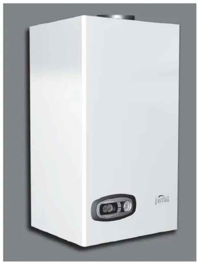
fig.1 - Control panel
Key of panel fig. 1
1 DHW temperature setting decrease button
2 DHW temperature setting increase button
3 Heating system temperature setting decrease button
4 Heating system temperature setting increase button
5 Display
6 "Sliding Temperature" Menu - Summer/Winter mode selection - Reset button
7 Unit On/Off - Economy/Comfort mode selection button
8 DHW symbo
9 DHW mode
10 Summer mode
11 Multifunction
12 Eco (Economy) mode
13 Heating
14 Heating symbol
15 Burner lit and actual power level (flashing during combustion fault function)
16 Service Tool connection
17 Water gauge
Indication during operation
Heating
A heating demand (generated by the Room Thermostat or Remote Timer Control) is indicated by flashing of the hot air above the radiator on the display.
The display (detail 11 - fig. 1) shows the actual heating delivery temperature and, during heating standby time, the message "d2".
Domestic hot water (DHW)
A DHW demand (generated by drawing domestic hot water) is indicated by flashing of the hot water under the tap on the display.
The display (detail 11 - fig. 1) shows the actual DHW outlet temperature and, during DHW standby time, the message "d1".
Comfort
A Comfort demand (reinstatement of temperature inside the boiler) is indicated by flashing of the water under the tap on the display. The display (detail 11 - fig. 1) shows the actual temperature of the water in the boiler.
Fault
In case of a fault (see cap. 4.4) the display shows the fault code (detail 11 - fig. 1) and during safety pause times the messages "d3", "d4" and "d5".
2.3 Lighting and shutdown
Connection to the power supply
- During the first 5 seconds the display will also show the card software release.
- Open the gas cock ahead of the boiler.
- The boiler is now ready to function automatically whenever domestic hot water is drawn or in case of a heating demand (generated by Room Thermostat or Remote Temperature Control).
Turning the boiler off and on
Press the on/off button (detail 7 - fig. 1) for 5 seconds.

fig. 2 - Turning the boiler off
When the boiler is turned off, the circuit board is still powered. Domestic hot water and heating are disabled. The frost protection system remains activated. To relight the boiler, press the on/off button (detail 7 fig. 1) again for 5 seconds.
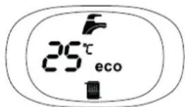
fig. 3
The boiler will be immediately ready to work whenever domestic hot water is drawn or in case of a heating demand (generated by the Room Thermostat or the Remote Timer control).
The frost protection system does not work when the power and/or gas to the unit are turned off. To avoid damage caused by freezing during long shutdowns in winter, it is advisable to drain all water from the boiler, the DHW circuit and the heating system water; or drain just the DHW circuit and add a suitable antifreeze to the heating system, as prescribed in sec. 3.3.
2.4 Adjustments
Summer/Winter Sustainover
Press the summer/winter button (detail 6 - fig. 1) for 2 seconds.
The display activates the Summer symbol (detail 10 - fig. 1): the boiler will only deliver domestic hot water. The antifreeze system remains activated.
To deactivate the Summer mode, press the summer/winter button (detail 6 - fig. 1) again for 2 seconds.
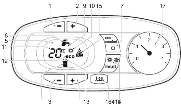
Heating temperature adjustment
Use the heating buttons (details 3 and 4 - fig. 1) to adjust the temperature from a min. of 30^ to a max. of 80^ ; in any case, it is advisable not to operate the boiler below 45^ .
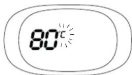
fig. 4
DHW temperature adjustment
Use the DHW buttons (details 1 and 2 - fig. 1) to adjust the temperature from a min. of 40^ to a max. of 55^ .
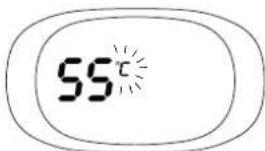
fig.5
Room temperature adjustment (with optional room thermostat)
Using the room thermostat, set the temperature required in the rooms. If the room thermostat is not installed, the boiler will keep the system at the set system delivery setpoint temperature.
Room temperature adjustment (with optional remote timer control)
Using the remote timer control, set the required temperature in the rooms. The boiler will adjust the system water according to the required room temperature. For operation with remote timer control, please refer to the relevant instruction manual.
ECO/COMFORT selection
The unit has a function that ensures a high domestic hot water delivery speed and maximum comfort for the user. When the device is activated (COMFORT mode), the water contained in the boiler is kept hot, thereby ensuring immediate availability of hot water on opening the tap, without waiting times.
The user can deactivate the device (ECO mode) by pressing the eco/comfort button (detail 7 - fig. 1). In ECO mode the display activates the ECO symbol (detail 12 - fig. 1). To activate the COMFORT mode, press the eco/comfort button (detail 7 - fig. 1) again.
Sliding Temperature
When the optional external probe is installed the boiler adjustment system works with "Sliding Temperature". In this mode, the heating system temperature is regulated according to weather conditions, to ensure the high comfort and energy efficiency throughout the year. In particular, as the outside temperature increases the system delivery temperature decreases according to a specific "compensation curve".
With the Sliding Temperature adjustment, the temperature set with the heating buttons (detail 3 - fig. 1) becomes the maximum system delivery temperature. It is advisable to set a maximum value to allow system adjustment throughout its useful operating range.
The boiler must be adjusted at the time of installation by qualified personnel. However, the user can make any further adjustments necessary to optimise comfort levels.
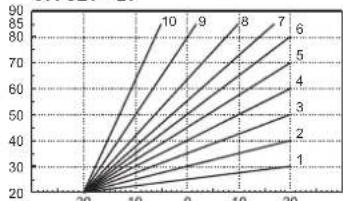
Compensation curve and curve offset
Press the reset button (detail 6 - fig. 1) for 5 seconds to access the "Sliding temperature" menu; the display shows "CU" flashing.
Use the DHW buttons (detail 1 - fig. 1) to adjust the desired curve from 1 to 10 according to the characteristic (fig. 6). By setting the curve to 0, the sliding temperature adjustment is disabled.
Press the heating buttons (detail 3 - fig. 1) to access parallel curve offset; the display shows "OF" flashing. Use the DHW buttons (detail 1 - fig. 1) to adjust parallel curve offset according to the characteristic (fig. 7).
Press the reset button (detail 6 - fig. 1) again for 5 seconds to exit the "Sliding Temperature" menu.
If the room temperature is lower than the required value, it is advisable to set a higher order curve and vice versa. Proceed by increasing or decreasing in steps of one and check the result in the room.
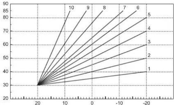
fig.6 - Compensation curves
OFFSET=20
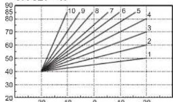
OFFSET=40
fig. 7 - Example of compensation parallel curve offset
Adjustments from Remote Timer Control

If the Remote Timer Control (optional) is connected to the boiler, the above adjustments are managed according to that given in table 1.
Table. 1
| Heating temperature setting | Adjustment can be made from the Remote Timer Control menu and the boiler control panel. |
| DHW temperature adjustment | Adjustment can be made from the Remote Timer Control menu and the boiler control panel. |
| Summer/Winter Switchover | Summer mode has priority over a possible Remote Timer Control heating demand. |
| Eco/Comfort selection | On disabling DHW from the Remote Timer Control menu, the boiler selects the Economy mode. In this condition, the eco/comfort button (detail 7 - fig. 1) on the boiler panel is disabled. |
| On enabling DHW from the Remote Timer Control menu, the boiler selects the Comfort mode. In this condition it is possible select one of the two modes with the eco/comfort button (detail 7 - fig. 1) on the boiler panel. | |
| Sliding Temperature | Both the Remote Timer Control and the boiler card manage Sliding Temperature adjustment: the boiler card Sliding Temperature has priority. |
System water pressure adjustment
The filling pressure read on the boiler water gauge (detail 2 - fig. 8) with system cold must be approx 1.0 bar. If the system pressure falls below minimum values, the boiler stops and fault F37 is displayed. Pull out the filling knob (detail 1 - fig. 8) and turn it anticlockwise to return it to the initial value. Always close it afterwards.
Once the system pressure is restored, the boiler will activate the 300-second air venting cycle indicated on the display by Fh.
To prevent boiler shutdown, it is advisable to periodically check the pressure on the gauge with system cold. In case of a pressure below 0.8 bar, it is advisable to restore it.
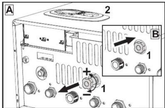
fig. 8- Filling knob
System draining
The drain faucet ring nut is located under the safety valve inside the boiler.
To drain the system, turn the ring (ref. 1 - fig. 9) counter-clockwise to open the faucet. Do not use any tools; use hands only.
To drain only the water in the boiler, first close the shut-off valves between the system and boiler before turning the ring.
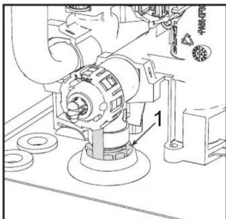
fig. 9-Safety valve with drain faucet
3. INSTALLATION
3.1 General Instructions
BOILER INSTALLATION MUST ONLY BE PERFORMED BY QUALIFIED PERSONNEL, IN ACCORDANCE WITH ALL THE INSTRUCTIONS GIVEN IN THIS TECHNICAL MANUAL, THE PROVISIONS OF CURRENT LAW, THE PRESCRIPTIONS OF NATIONAL AND LOCAL STANDARDS AND THE RULES OF PROPER WORKMANSHIP.
3.2 Place of installation

This unit is an "open chamber" type and can only be installed and operated in permanently ventilated rooms. An insufficient flow of combustion air to the boiler will affect its normal operation and fume evacuation. Also, the fumes forming under these conditions are extremely harmful to health if dispersed in the domestic environment.
The unit is designed to operate in a partially protected place, with a minimum temperature of -5^ . If provided with the special antifreeze kit, it can be used with a minimum temperature down to -15^ . The boiler must be installed in a sheltered place, for instance under the slope of a roof, inside a balcony or in a protected recess.
The place of installation must be free of flammable materials, objects and dusts or corrosive gases.
The boiler is arranged for wall mounting and comes as standard with a hooking bracket. Wall fixing must ensure stable and effective support for the generator.

If the unit is enclosed in a cabinet or mounted alongside, there must be sufficient space for removing the casing and for normal maintenance activities
3.3 Plumbing connections
Important

The safety valve outlet must be connected to a funnel or collection pipe to prevent water spurting onto the floor in case of overpressure in the heating circuit. Otherwise, if the discharge valve cuts in and floods the room, the boiler manufacturer cannot be held liable.

Before making the connection, check that the unit is arranged for operation with the type of fuel available and carefully clean all the system pipes.
Carry out the relevant connections according to the diagram in fig. 2.3 and the symbols on the unit.
Note: The unit is equipped with an internal bypass in the heating circuit.
Water system characteristics
In the presence of water harder than 25^ r (1^ = 10ppmCaCO_3) use suitably treated water in order to avoid possible scaling in the boiler.
Antifreeze system, antifreeze fluids, additives and inhibitors
When necessary, antifreeze fluids, additives and inhibitors can be used only if the manufacturer of such fluids or additives guarantees that they are suitable and do not cause damage to the exchanger or other components and/or materials of the boiler and system. Do not use generic antifreeze fluids, additives or inhibitors that are not specific for use in heating systems and compatible with the materials of the boiler and system.
3.4 Gas connection
The gas must be connected to the relevant connection (see fig. 2.3) in conformity with the current standards, using a rigid metal pipe or a continuous surface flexible s/steel tube and installing a gas cock between the system and boiler. Make sure all the gas connections are tight.
3.5 Electrical connections
IMPORTANT

BEFORE CARRYING OUT ANY OPERATION THAT REQUIRES REMOVING THE CASING, DISCONNECT THE BOILER FROM THE ELECTRIC MAINS WITH THE MAIN SWITCH.
NEVER TOUCH THE ELECTRICAL COMPONENTS OR CONTACTS WITH THE MAIN SWITCH TURNOED ON! DANGER OF ELECTRIC SHOCK WITH RISK OF INJURY OR DEATH!

The unit must be connected to an efficient grounding system in accordance with applicable safety regulations. Have the efficiency and suitability of the grounding system checked by professionally qualified personnel; the Manufacturer declines any liability for damage caused by failure to earth the system.
The boiler is prewired and provided with a three-pole cable, without a plug, for connection to the electric line. The connections to the grid must be made with a permanent connection and equipped with a bipolar switch whose contacts have a minimum opening of at least 3mm , interposing fuses of max. 3A between the boiler and the line. Make sure to respect the polarities (LINE: brown wire / NEUTRAL: blue wire / GROUND: yellow-green wire) in the connections to the electric line.

The unit's supply cable MUST NOT BE REPLACED BY THE USER. If the cable gets damaged, turn the unit off and have the cable replaced only by professionally qualified personnel. In case of replacement, only use cable "HAR H05 VV-F" 3 × 0.75 ~mm^2 with max. external diameter of 8 ~mm .
Room thermostat (optional)

IMPORTANT: THE ROOM THERMOSTAT MUST HAVE VOLTAGE-FREE CONTACTS. CONNECTING 230 V TO THE ROOM THERMOSTAT TERMINALS WILL PERMANENTLY DAMAGE THE ELECTRONIC BOARD.
When connecting time controls or a timer, do not take the power supply for these devices from their breaking contacts. Their power supply must be by means of direct connection from the mains or with batteries, depending on the kind of device.
Accessing the electrical terminal block
The electrical terminal block can be accessed after removing the casing. The layout of the terminals for the various connections is also given in the wiring diagram in fig. 23.
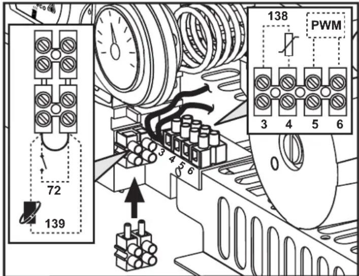
fig. 10 - Accessing the terminal block
3.6 Air/fume ducts
The diameter of the flue connection pipe must not be less than that of the connection on the anti-backflow device. Starting from the anti-backflow device it must have a vertical section at least 50~cm long. Current standards must be complied with regarding sizing and installation of the flues and connection pipe.

The boiler is also equipped with a safety device (fume thermostat) that stops operation of unit in case of inadequate draught of obstruction of the flue. This device must never be tampered with or deactivated.
4. SERVICE AND MAINTENANCE
Important

All adjustment, conversion, commissioning and maintenance operations described below must only be carried out by Qualified Personnel (meeting the professional technical requirements of current regulations) such as the personnel of the Local After-Sales Technical Service.
FERROLI declines any liability for damage and/or injury caused by unqualified and unauthorized persons tampering with the unit.
4.1 Adjustments
Gas conversion
ALL COMPONENTS DAMAGED DURING CONVERSION OPERATIONS MUST BE REPLACED.
The unit can operate on natural gas or LPG and is factory-set for use with one of these two gases, as clearly shown on the packing and on the data plate. Whenever a gas different from that for which the unit is arranged has to be used, the special conversion kit will be required, proceeding as follows:
- Disconnect the boiler power supply and close the gas cock.
- Replace the nozzles at the main burner, fitting the nozzles specified in the technical data table in cap. 5, according to the type of gas used
- Switch the boiler power on and open the gas cock.
-
Modify the parameter for the type of gas:
-
put the boiler in standby mode
- press the DHW buttons details 1 and 2 - fig. 1 for 10 seconds: the display shows "b01" flashing.
- press the DHW buttons details 1 and 2 - fig. 1 to set the parameter 00 (for natural gas operation) or 01 (for LPG operation).
-
press the DHW buttons details 1 and 2 - fig. 1 for 10 seconds.
the boiler will return to standby mode -
Adjust the minimum and maximum pressures at the burner (ref. relevant paragraph), setting the values given in the technical data table for the type of gas used
- Apply the sticker contained in the conversion kit, near the data plate as proof of the conversion.
Activation of Auto-setting function for gas valve calibration
THIS PROCEDURE MUST ONLY BE CARRIED OUT IN THE FOLLOWING CASES: GAS VALVE REPLACEMENT, CARD REPLACEMENT, CONVERSION FOR GAS CHANGE.
The B&P Gas Valve (with integrated modulating operator) does not provide for mechanical calibration: the minimum and maximum power adjustments are therefore electronically done via two parameters:
| Contents | Description | Natural Gas | Propane Gas |
| q01 | Absolute minimum current offset 0÷100 | 0÷150 | |
| q02 | Absolute maximum current offset | 0÷100 | 0-150 |
Gas valve pre-calibration
- Connect a pressure gauge to monitor the gas valve outlet pressure.
- Enable the Auto-setting function (Parameter b12=1).
- Activate the calibration procedure by pressing the heating + button and Eco/Comfort button together for 5 seconds. The message "Au-to" immediately appears (in two successive flashes) and the burner is lit. Within 8 seconds (natural gas and LPG) the boiler finds the ignition point. The ignition point, absolute minimum current Offset (Parameter q01) and absolute maximum current Offset (Parameter q02) values are stored by the card.
Gas valve calibration
- The display will show "q02" flashing; the modulation current is forced to the pre-calibration value of the absolute maximum current Offset parameter (Parameter q02)
- Press the DHW buttons to adjust the parameter "q02" until the maximum nominal pressure minus 1mbar is reached on the pressure gauge. Wait 10 seconds for the pressure to stabilise.
- Press the DHW "+?" button to set the parameter "q02" until the maximum nominal pressure is reached on the pressure gauge. Wait 10 seconds for the pressure to stabilise.
- If the pressure read on the pressure gauge is different from the maximum nominal pressure, proceed in increments of 1 or 2 units of the parameter "q02" by pressing the DHW "+" button: after each change, wait 10 seconds for the pressure to stabilise.
- When the pressure read on the pressure gauge is equal to the maximum nominal pressure (the newly calibrated value of the parameter "q02" is automatically saved), press the heating - button: the display will show "q01" flashing; the modulation current is forced to the pre-calibration value of the absolute minimum current Offset parameter (Parameter q01).
- Press the DHW buttons to adjust the parameter "q01" until the minimum nominal pressure plus 0.5mbar is reached on the pressure gauge. Wait 10 seconds for the pressure to stabilise.
- Press the DHW "..." button to adjust the parameter "q01" until the minimum nominal pressure is reached on the pressure gauge. Wait 10 seconds for the pressure to stabilise.
- If the pressure read on the pressure gauge is different from the minimum nominal pressure, proceed in decrements of 1 or 2 units of the parameter "q01" by pressing the DHW "..." button: after each change, wait 10 seconds for the pressure to stabilise
- When the pressure read on the pressure gauge is equal to the minimum nominal pressure (the newly calibrated value of the parameter "q01" is automatically saved.), recheck both adjustments by pressing the healing buttons and correct them if necessary by repeating the procedure described above.
- The calibration procedure ends automatically after 15 minutes or by pressing the heating "+" and Eco/Comfort buttons together for 5 seconds.
Checking of gas pressure values and adjustment with limited range
- Check that the supply pressure complies with that indicated in the technical data table.
- Connect a suitable pressure gauge to the pressure sampling point "B" located downstream from the gas valve.
- Activate the TEST mode and follow the instructions for checking the gas pressures at maximum power and minimum power (see next par.).
If the maximum and/or minimum nominal pressures read on the pressure gauge are different from those indicated in the technical data table, proceed with the next sequence.
- Press the Eco/Comfort button for 2 seconds to go to the gas valve Calibration with limited range mode.
The card goes to the setting "q02"; displaying the currently saved value by pressing the DHW buttons. - If the maximum pressure read on the pressure gauge is different from the nominal one, proceed in increments/decrements of 1 or 2 units of the parameter "q02" by pressing the DHW buttons: after each change, the value is stored; wait 10 seconds for the pressure to stabilise.
- Press the heating " - button (ref. 3 - fig. 1).
- The card goes to the setting "q01"; displaying the currently saved value by pressing the DHW buttons.
- If the minimum pressure read on the pressure gauge is different from the nominal one, proceed in increments/decrements of 1 or 2 units of the parameter "q01" by pressing the DHW buttons: after each change, the value is stored; wait 10 seconds for the pressure to stabilise.
- Recheck both settings by pressing the heating buttons and if necessary correct them by repeating the procedure described above.
- Pressing the Eco/Comfort button for 2 seconds returns to TEST mode.
- Deactivate TEST mode (see next par.).
- Disconnect the pressure gauge
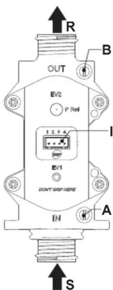
fig. 11 - Gas valve
A - Upstream pressure point
B-Downstream pressure point
I-Gas valve electrical connection
R-Gas outlet
S-Gas inlet
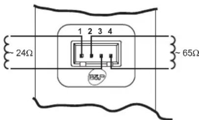
fig. 12 - Gas valve connection
TYPE SGV100
PI max 65 mbar
24 Vdc-class B+A
TEST mode activation
Press the heating buttons (details 3 and 4 - fig. 1) together for 5 seconds to activate the TEST mode. The boiler lights at the maximum heating power set as described in the following section.
The heating and DHW symbols (fig. 13) flash on the display; the heating power will appear alongside.
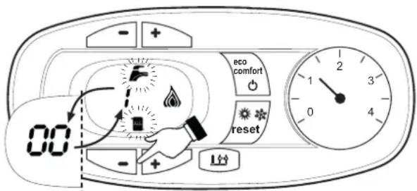
fig.13 - TEST mode (heating power = 100%
Press the heating buttons (details 3 and 4 - fig. 1) to increase or decrease the power (Min. = 0%, Max. = 100%).
By pressing the DHW "+" button (detail 1 - fig. 1), boiler output is immediately adjusted to min. (0%) . By pressing the DHW "+" button (detail 2 - fig. 1), boiler output is immediately adjusted to max. (100%) .
If the TEST mode is activated and enough hot water is drawn to activate the DHW mode, the boiler remains in TEST mode but the 3-way valve goes to DHW.
To deactivate the TEST mode, press the heating buttons (details 3 and 4 - fig. 1) together for 5 seconds.
The TEST mode is automatically deactivated in any case after 15 minutes or on stopping of hot water drawing (if enough hot water has been drawn to activate the DHW mode).
Heating power adjustment
To adjust the heating power, switch the boiler to TEST mode (see sec. 4.1). Press the heating buttons detail 3 - fig. 1 to increase or decrease the power (min. = 00 - max. = 100). Press the reset button within 5 seconds and the max. power will remain that just set. Exit TEST mode (see sec. 4.1).
Configuration Menu
The configuration Menu is accessed by pressing the DHW buttons together for 10 seconds. 12 parameters, indicated by the letter "b" and not modifiable from Remote Timer Control, are available.
Press the Heating buttons to scroll the list of parameters in increasing or decreasing order. Press the DHW buttons to view or modify the value of a parameter: the change will be automatically saved.
| Contents | Description Range Parameter | ||
| b01 | Gas type selection | 0 = Natural Gas | 0 |
| 1 = LPG | |||
| b02 | Boiler type selection | 2 | |
| b03 | Combustion chamber type selection | 5 = LOW NOx Open Chamber(with fume thermostat) | 5 |
| b04 | Primary Exchanger type selection 0 ÷ | 13 | 4 (for model C24)5 (for model C30) |
| b05 | --- | 0 | |
| b06 | Mains Voltage Frequency | 0 = 50Hz | 0 |
| 1 = 60Hz | |||
| b07 | --- | 5 | |
| b08 | Gas valve driver 0 = Standard, 1 0 | ||
| b09 | DHW demand type selection 1 = Flowmeter (190 imp/t) 1 | ||
| b10 | Flowmeter timing | 0 = Deactivated1-10=seconds | 0 |
| b11 | DHW mode activation flow rate | 10 ÷ 100 L/min/10 | 15 |
| b12 | Enable Auto-Settings procedure | 0 = Disabled1 = Enabled | 0 |
Notes:
- Parameters with more than one description vary their function and/or range in relation to the setting of the parameter given in brackets.
- Parameters with more than one description are reset to the default value if the parameter given in brackets is modified.
To exit the configuration Menu press the DHW buttons together for 10 seconds, or exiting occurs automatically after 2 minutes.
Service menu
The card Service Menu is accessed by pressing the Reset button for 20 seconds. 4 sub menus are available: press the Heating buttons to select, in increasing or decreasing order, "tS", "In", "Hi" or "rE". "tS" means Transparent Parameters Menu, "In" means Information Menu, "Hi" means History Menu; after selecting the submenu, press the Reset button again to access it; "rE" means History Menu Reset: see description.
“tS”-Transparent Parameters Menu
21 parameters indicated by the letter "P" are available, which are also modifiable from Remote Timer Control.
Press the Heating buttons to scroll the list of parameters in increasing or decreasing order. Press the DHW buttons to view or modify the value of a parameter: the change will be automatically saved.
| Contents | Description | Range | DIVAtech D LN C |
| P01 | Ignition ramp Offset | 0-40 | 20 |
| P02 | Heating ramp | 1-20°C/minute | 5 |
| P03 | Heating standby time | 0-10 minutes | 2 |
| P04 | Heating Post-Circulation | 0-20 minutes | 6 |
| P05 | Heating user max. setpoint | 31-85°C | 80 |
| P06 | Max. output in heating | 0-100% | 100 |
| P07 | Burner shutdown in DHW | 0=Fixed | 0 |
| 1=Linked to set point | |||
| 2=Solar | |||
| 3 = DO NOT USE | |||
| 4 = DO NOT USE | |||
| P08 | DHW standby time | 0-60 seconds | 30 |
| P09 | DHW user max. setpoint | 50-65°C | 50 |
| P10 | No effect on adjustment | -- | 0 |
| P11 | DHW Post-Circulation | 0-60 Seconds | 30 |
| P12 | Max. output in DHW | 0-100% | 100 |
| P13 | Absolute min. power | 0-100% | 0 |
| P14 | NOT AVAILABLE FOR THIS MODEL | ||
| P15 | No effect on adjustment (b03=5) | -- | |
| P16 | Exchanger protection activation | 0=No F43 | 10 |
| 1-15=1-15°C/second | |||
| P17 | Modulating pump max. speed - absolute | Operating at 100%. Adjustable with optional cable. | 100 |
| P18 | Modulating pump max. speed - post circulation | 0-100% not operating. Always at 100% in this model | 60 |
| P19 | Solar deactivation temperature | 0-20°C | 10 |
| P20 | Solar ignition temperature | 0-20°C | 10 |
| P21 | Solar standby time | 0-20 seconds | 10 |
Notes:
- Parameters with more than one description vary their function and/or range in relation to the setting of the parameter given in brackets.
- Parameters with more than one description are reset to the default value if the parameter given in brackets is modified.
- The Maximum Heating Power parameter can also be modified in Test Mode.
Press the Reset button to return to the Service Menu. Press the Reset button for 20 seconds to exit the card Service Menu, or exiting occurs automatically after 15 minutes.
"In" - Information Menu
9 pieces of information are available.
Press the Heating buttons to scroll the list of information in increasing or decreasing order. Press the DHW buttons to display the value.
| Contents | Description | Range |
| t01 | NTC Heating sensor (°C) | between 05 and 125°C |
| t02 | NTC Safety sensor (°C) | between 05 and 125°C |
| t03 | NTC DHW sensor (°C) | between 05 and 125°C |
| t04 | NTC External sensor (°C) | between -30 and 70°C (negative values flash)Without NTC = -- |
| L05 | Actual burner power (%) | 00%=Min., 100%=Max. |
| F06 | Actual Flame resistance (kOhm) | 00-99 kOhm (--)=burner off! |
| St07 | NOT AVAILABLE FOR THIS MODEL | |
| F08 | Actual DHW drawing (L min/10) | L min/10 over 99 flashing 3 figures |
| PP09 | Actual modulating pump speed (%): 00:100% not working in this model | |
Notes:
- In case of damaged sensor, the card displays hyphens.
Press the Reset button to return to the Service Menu. Press the Reset button for 20 seconds to exit the card Service Menu or exiting occurs automatically after 15 minutes.
"Hi" - History Menu
The card can store the last 11 faults: the History datum item H1: represents the most recent fault that occurred; the History datum item H10: represents the least recent fault that occurred.
The codes of the faults saved are also displayed in the corresponding menu of the Remote Timer Control.
Press the Heating buttons to scroll the list of faults in increasing or decreasing order. Press the DHW buttons to display the value.
Press the Reset button to return to the Service Menu. Press the Reset button for 20 seconds to exit the card Service Menu, or exiting occurs automatically after 15 minutes.
"rE"-History Reset
Press the Eco/Comfort button for 3 seconds to delete all the faults stored in the History Menu: the card will automatically exit the Service Menu, in order to confirm the operation. Press the Reset button for 20 seconds to exit the card Service Menu, or exiting occurs automatically after 15 minutes.
4.2 Commissioning
Before lighting the boller
- Check the seal of the gas system.
- Check correct prefilling of the expansion tank.
- Fill the water system and make sure all air contained in the boiler and the system has been vented.
Make sure there are no water leaks in the system, DHW circuits, connections or boiler. - Check correct connection of the electrical system and efficiency of the earthing system.
- Make sure the gas pressure for heating is that required.
- Make sure there are no flammable liquids or materials in the immediate vicinity of the boiler

IF THE ABOVE INSTRUCTIONS ARE NOT OBSERVED THERE MAY BE RISK OF SUFFOCATION OR POISONING DUE TO GAS OR FUMES ESCAPING; DANGER OF FIRE OR EXPLOSION. ALSO, THERE MAY BE A RISK OF ELECTRIC SHOCK OR FLOODING THE ROOM.
Checks during operation
- Switch the unit on.
- Check the tightness of the fuel circuit and water systems.
- Check the efficiency of the flue and air/fume ducts while the boiler is working
- Make sure the water is circulating properly between the boiler and the systems.
- Make sure the gas valve modulates correctly in the heating and domestic hot water production stages.
- Check correct boiler lighting by performing various tests, turning it on and off with the room thermostat or remote control.
- Make sure the fuel consumption indicated on the meter matches that given in the technical data table in cap. 5.
- Make sure that with no demand for heating, the burner lights correctly on opening a hot water tap. Check that in heating mode, on opening a hot water tap, the heating circulating pump stops and there is regular production of hot water.
- Make sure the parameters are programmed correctly and carry out any required customisation (compensation curve, power, temperatures, etc.).
4.3 Maintenance
IMPORTANT

ALL MAINTENANCE WORK AND REPLACEMENTS MUST BE CARRIED OUT BY SKILLED QUALIFIED PERSONNEL.
Before carrying out any operation inside the boiler, disconnect the power and close the gas cock upstream. Otherwise there may be a danger of explosion, electric shock, suffocation or poisoning.
Periodical inspection
To ensure proper operation of the unit over time, have qualified personnel carry out a yearly inspection, providing for the following checks:
- The control and safety devices (gas valve, flow switch, thermostats, etc.) must function correctly.
- The fume exhaust circuit must be perfectly efficient. (Sealed chamber boiler: fan, pressure switch, etc. - The sealed chamber must be tight: seals, cable glands, etc.) (Open chamber boiler: anti-backflow device, fume thermostat, etc.)
The air/fume terminal and ducts must be free of obstructions and leaks - The burner and exchanger must be clean and free of deposits. Do not use chemical products or wire brushes to clean.
The electrode must be properly positioned and free of deposits.
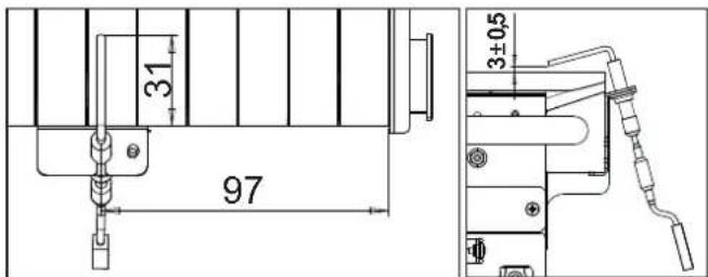
fig. 14 - Electrode positioning
The gas and water systems must be tight.
The pressure of the water in the system when cold must be approx. 1 bar; otherwise, bring it to that value.
The circulating pump must not be blocked.
The expansion tank must be filled.
- The gas flow and pressure must match that given in the respective tables.
4.4 Troubleshooting
Diagnostics
The boiler has an advanced self-diagnosis system. In case of a boiler fault, the display will flash together with the fault symbol (detail 11 - fig. 1) indicating the fault code.
There are faults that cause permanent shutdowns (marked with the letter "A"): to restore operation, press the RESET button (detail 6 - fig. 1) for 1 second or RESET on the optional remote timer control if installed. At this point the display will show "d4" for about 30 seconds or "d5" for about 5 minutes which indicates the waiting time after which the boiler will resume normal operation. If the boiler fails to restart, it is necessary to eliminate the fault.
Other faults cause temporary shutdowns (marked with the letter "F") which are automatically reset as soon as the value returns within the boiler's normal working range.
List of faults
Table. 2
| Fault code | Fault Possible cause Cure | ||
| A01 | No burner ignition | No gas | Check the regular gas flow to the boiler and that the air has been eliminated from the pipes |
| Ignition/detection electrode fault | Check the wiring of the electrode and that it is correctly positioned and free of any deposits | ||
| Faulty gas valve | Check the gas valve and replace it if necessary | ||
| Gas valve wiring disconnected | Check the wiring | ||
| Ignition power too low Adjust the | Ignition power | ||
| A02 | Flame present signal with burner off | Electrode fault | Check the ionisation electrode wiring |
| Card fault Check the card | |||
| A03 | Overtemperature protection activation | Heating sensor damaged | Check the correct positioning and operation of the heating sensor |
| No water circulation in the system | Check the circulating pump | ||
| Air in the system Vent the system | |||
| F04 | Fume thermostat activated (after activation of the fume thermostat, boiler operation is prevented for 20 minutes) | Fume thermostat contact open | Check the thermostat |
| Wiring disconnected Check the wiring | |||
| Flue obstructed or not correctly sized | Check the flue |
| Fault code | Fault Possible cause Cure | ||
| F05 | Card parameter fault Wrong card parameter setting | Check the card parameter and modify it if necessary | |
| A06 | No flame after the ignition phase | Low pressure in the gas system | Check the gas pressure |
| Burner minimum pressure setting | Check the pressures | ||
| F07 | Card parameter fault Wrong card parameter setting | Check the card parameter and modify it if necessary | |
| A09 | Gas valve fault | Wiring disconnected Check the wiring | |
| Faulty gas valve | Check the gas valve and replace it if necessary | ||
| F10 | Delivery sensor 1 fault | Sensor damaged | Check the wiring or replace the sensor |
| Wiring shorted | |||
| Wiring disconnected | |||
| F11 | DHW sensor fault | Sensor damaged | Check the wiring or replace the sensor |
| Wiring shorted | |||
| Wiring disconnected | |||
| F14 | Delivery sensor 2 fault | Sensor damaged | Check the wiring or replace the sensor |
| Wiring shorted | |||
| Wiring disconnected | |||
| A16 | Gas valve fault | Wiring disconnected Check the wiring | |
| Faulty gas valve | Check the gas valve and replace it if necessary | ||
| F20 | Card parameter fault Wrong card parameter setting | Check the card parameter and modify it if necessary | |
| A21 | Card parameter fault Wrong card parameter setting | Check the card parameter and modify it if necessary | |
| A23 | Card parameter fault Wrong card parameter setting | Check the card parameter and modify it if necessary | |
| A24 | Card parameter fault Wrong card parameter setting | Check the card parameter and modify it if necessary | |
| F34 | Supply voltage under 170V. | Electric mains trouble | Check the electrical system |
| F35 | Faulty mains frequency | Electric mains trouble | Check the electrical system |
| F37 | Incorrect system water pressure | Pressure too low | Fill the system |
| Water pressure switch damaged or not connected | Check the sensor | ||
| F39 | External probe fault | Probe damaged or wiring shorted | Check the wiring or replace the sensor |
| Probe disconnected after acti- vating the sliding temperature | Reconnect the external sensor or disable the sliding temperature | ||
| A41 | Sensor positioning | Delivery sensor detached from the pipe | Check the correct positioning and operation of the sensor |
| F42 | Heating sensor fault | Sensor damaged | Replace the sensor |
| F43 | Exchanger protection trips. | No system \( H_2O \)circulation | Check the circulating pump |
| Air in the system | Vent the system | ||
| F50 | Gas valve fault | Modulating Operator wiring dis- connected | Check the wiring |
| Faulty gas valve | Check the gas valve and replace it if necessary | ||
| A51 | Card parameter fault Wrong card parameter setting | card parameter setting | Check the card parameter and modify it if necessary |
5. TECHNICAL DATA AND CHARACTERISTICS
Table. 3-Legend, fig.20, fig.21 and fig.22
| 8 | DHW outlet - Ø 1/2" | 56 | Expansion vessel |
| 9 | DHW inlet - Ø 1/2" | 74 | System filling faucet |
| 10 | System delivery - Ø 3/4" | 78 | Anti-backflow device |
| 11 | System return - Ø 3/4" | 81 | Ignition and detection electrode |
| 14 | Safety valve | 95 | Divertor valve |
| 22 | Burner | 114 | Water pressure switch |
| 27 | Copper exchanger for heating and DHW | 126 | Fume thermostat |
| 32 | Heating circulating pump | 136 | Flowmeter |
| 36 | Automatic air vent | 137 | Pressure sensor |
| 37 | Cold water inlet filter | 194 | DHW exchanger |
| 42 | DHW temperature sensor | 241 | Automatic bypass |
| 44 | Gas valve | 278 | Double sensor (Safety + heating) |
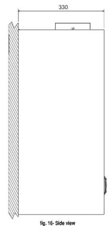
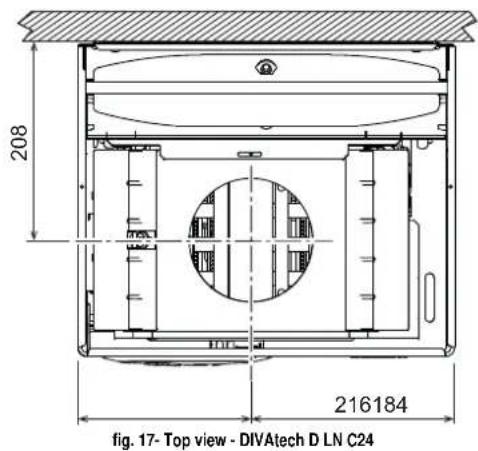
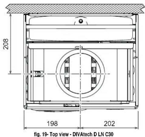
5.1 Dimensions and connections
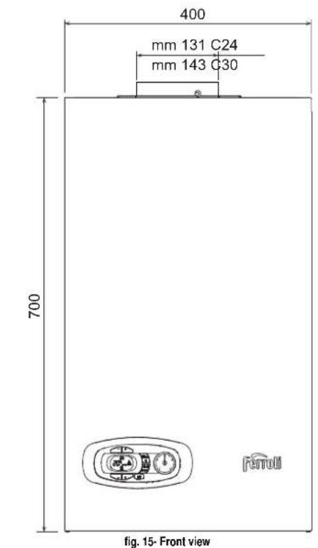
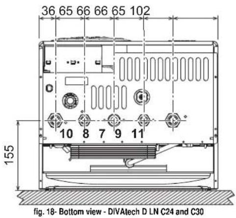
7 Gas inlet - 0 3/4"
8 DHW outlet - 01/2"
9 Cold water inlet - 0 1/2"
10 System delivery - 0 3/4"
11 System return - 0 3/4"
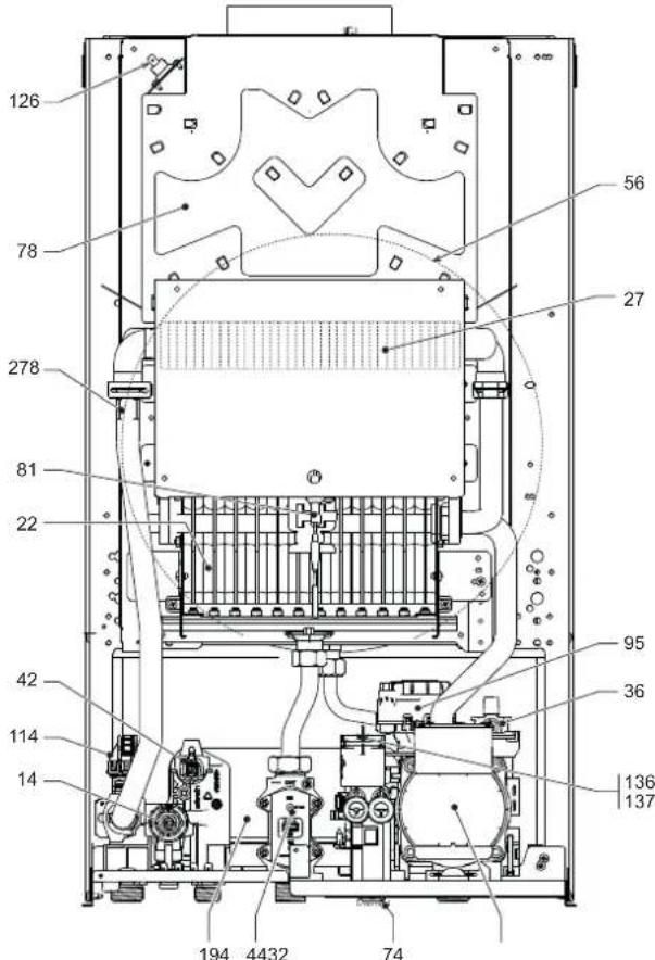
5.2 General view and main components
fig. 20- General view - DIVAtech D LN C24
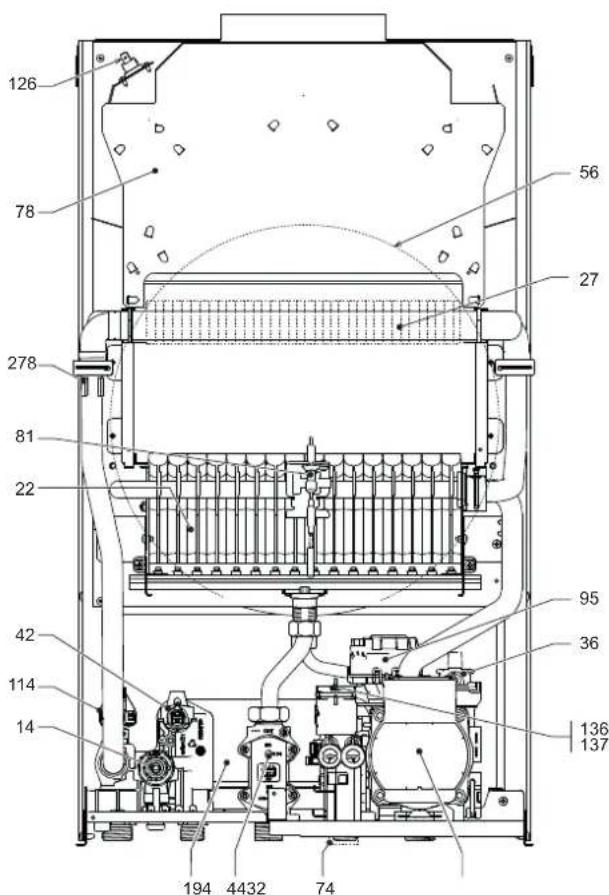
fig. 21- General view - DIVATEch D LN C30
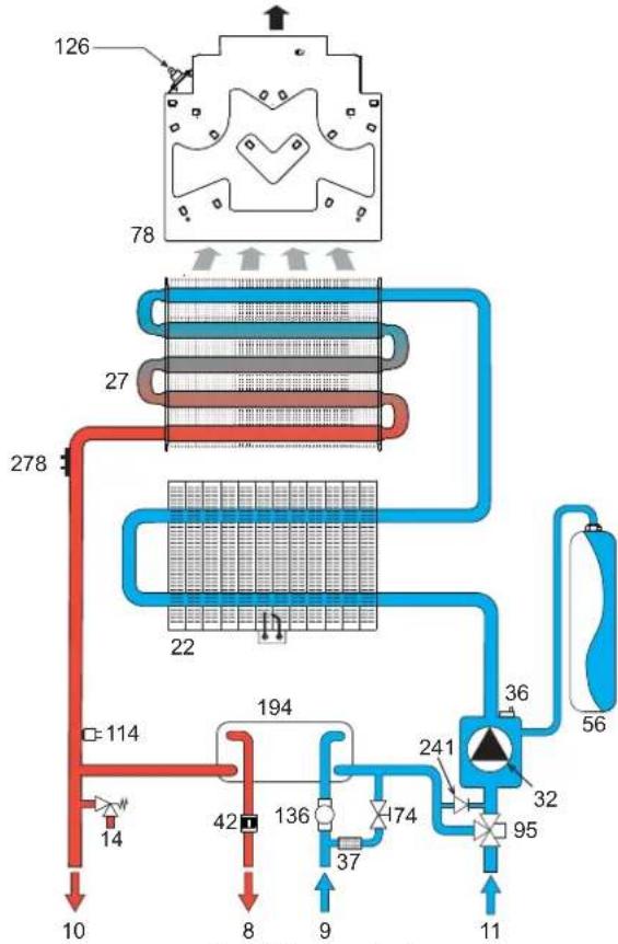
5.3 Hydraulic circuit
fig. 22- Heating circuit
5.4 Technical data table
| Data Unit DIVatech D LN C24 DIVatech D LN C30 | ||||
| Max. heating capacity (CH - DHW) kW 25.0 33.0 (Q) | ||||
| Min. heating capacity (CH - DHW) kW 8.3 12.6 (Q) | ||||
| Max. Heat Output in heating | kW | 22.8 30.0 | (P) | |
| Min. Heat Output in heating | kW | 7.3 11.1 | (P) | |
| Max. Heat Output in DHW | kW | 22.8 30.0 | ||
| Min. Heat Output in DHW | kW | 7.3 11.1 | ||
| Efficiency Pmax (60-60°C) | % | 91.2 91.0 | ||
| Efficiency 30% | % | 89.8 89.8 | ||
| NOx emissions class | - | 6 (<56 mg/kWh) | (NOx) | |
| Burner nozzles G20 | no. x Ω | 24 x 0.85 | 32 x 0.85 | |
| Gas supply pressure G20 | mbar | 20.0 20.0 | ||
| Max. gas pressure at burner (G20) | mbar | 15.0 15.0 | ||
| Min. gas pressure at burner (G20) | mbar | 2.0 | 2.0 | |
| Max. gas flow G20 | m3/h | 2.65 3.49 | ||
| Min. gas flow G20 | m3/h | 0.88 1.33 | ||
| Burner nozzles G31 | no. x Ω | 24 x 0.5 | 32 x 0.5 | |
| Gas supply pressure G31 | mbar | 37 | 37 | |
| Max. gas pressure at burner (G31) | mbar | 35.5 35.5 | ||
| Min. gas pressure at burner (G31) | mbar | 5.0 | 5.0 | |
| Max. gas flow G31 | kg/h | 1.94 | 2.56 | |
| Min. gas flow G31 | kg/h | 0.64 0.98 | ||
| Max. working pressure in heating | bar | 3 | 3 | (PMS) |
| Min. working pressure in heating | bar | 0.8 | 0.8 | |
| Max. heating temperature | °C | 90 | 90 | (tmax) |
| Heating water content | liters | 0.8 | 1.2 | |
| Heating expansion vessel capacity | liters | 8 | 10 | |
| Heating expansion vessel precharge pressure | bar | 1 | 1 | |
| Max. working pressure in DHW | bar | 9 | 9 | (PMW) |
| Min. working pressure in DHW | bar | 0.3 | 0.3 | |
| DHW flow rate,at 25°C | l/min | 13.1 17.2 | ||
| DHW flow rate,at 30°C | l/min | 10.9 14.3 | (D) | |
| Protection rating | IP | IPX4D | ||
| Power supply voltage | V/Hz | 230V/50Hz | ||
| Electrical power input | W | 48 | 52 | |
| Electrical power input in DHW | W | 48 | 52 | |
| Empty weight | kg | 27 | 30 | |
| Type of unit | B11BS | |||
ErP product fiche
MODEL: DIVATECH D LN C24 - (ODCC4YWA)
| Trademark: FERROLI | |||
| Condensing boiler: NO | |||
| Low-temperature boiler (**) : YES | |||
| B1 Boiler: YES | |||
| Combination heater: YES | |||
| Cogeneration space heater: NO | |||
| Item | Symbol | Unit | Value |
| Seasonal space heating energy efficiency class (from A+++ to D) | C | ||
| Rated heat output | Pn | kW | 23 |
| Seasonal space heating energy efficiency | ηs | % | 77 |
| Useful heat output | |||
| Useful heat output at rated heat output and high-temperature regime (*) | P4 | kW | 22,8 |
| Useful heat output at 30% of rated heat output and low-temperature regime (**) | P1 | kW | 4,5 |
| Useful efficiency | |||
| Useful efficiency at rated heat output and high-temperature regime (*) | η4 | % | 82,1 |
| Useful efficiency at 30% of rated heat output and low-temperature regime (**) | η1 | % | 80,9 |
| Auxiliary electricity consumption | |||
| At full load | elmax | kW | 0,015 |
| At part load | elmin | kW | 0,007 |
| In standby mode | PSB | kW | 0,003 |
| Other items | |||
| Standby heat loss | Pstby | kW | 0,140 |
| Ignition burner power consumption | Pign | kW | 0,000 |
| Annual energy consumption | QHE | GJ | 57 |
| Sound power level | LWA | dB | 51 |
| Emissions of nitrogen oxides | NOx | mg/kWh | 32 |
| For combination heaters | |||
| Declared load profile | XL | ||
| Water heating energy efficiency class (from A+ to F) | B | ||
| Daily electricity consumption | Qelec | kWh | 0,129 |
| Annual electricity consumption | AEC | kWh | 28 |
| Water heating energy efficiency | ηwh | % | 78 |
| Daily fuel consumption | Qfuel | kWh | 23,274 |
| Annual fuel consumption | AFC | GJ | 19 |
^ High-temperature regime means 60^ return temperature at heater inlet and 80^ feed temperature at heater outlet.
(1^*) Low temperature means for condensing boilers 30^ for low-temperature boilers 37^ and for other heaters 50^ return temperature [at heater inlet].
ErP product fiche
MODEL: DIVATECH D LN C30 - (ODCC6YWA)
| Trademark: FERROLI | |||
| Condensing boiler: NO | |||
| Low-temperature boiler (*): YES | |||
| B1 Boiler: YES | |||
| Combination heater: YES | |||
| Cogeneration space heater: NO | |||
| Item | Symbol | Unit | Value |
| Seasonal space heating energy efficiency class (from A+++ to D) | C | ||
| Rated heat output | Pn | kW | 30 |
| Seasonal space heating energy efficiency | ηs | % | 77 |
| Useful heat output | |||
| Useful heat output at rated heat output and high-temperature regime (*) | P4 | kW | 30,0 |
| Useful heat output at 30% of rated heat output and low-temperature regime (**) | P1 | kW | 6,1 |
| Useful efficiency | |||
| Useful efficiency at rated heat output and high-temperature regime (*) | η4 | % | 82,0 |
| Useful efficiency at 30% of rated heat output and low-temperature regime (**) | η1 | % | 80,9 |
| Auxiliary electricity consumption | |||
| At full load | emax | kW | 0,015 |
| At part load | elmin | kW | 0,007 |
| In standby mode | PSB | kW | 0,003 |
| Other items | |||
| Standby heat loss | Pstby | kW | 0,150 |
| Ignition burner power consumption | Pign | kW | 0,000 |
| Annual energy consumption | QHE | GJ | 77 |
| Sound power level | LWA | dB | 52 |
| Emissions of nitrogen oxides | NOx | mg/kWh | 30 |
| For combination heaters | |||
| Declared load profile | XL | ||
| Water heating energy efficiency class (from A+ to F) | B | ||
| Daily electricity consumption | Qelec | kWh | 0,134 |
| Annual electricity consumption | AEC | kWh | 28 |
| Water heating energy efficiency | ηwh | % | 77 |
| Daily fuel consumption | Qfuel | kWh | 25,865 |
| Annual fuel consumption | AFC | GJ | 21 |
(^) High-temperature regime means 60^ return temperature at heater inlet and 80^ feed temperature at heater outlet.
[**] Low temperature means for condensing boilers 30^ , for low-temperature boilers 37^ and for other heaters 50^ return temperature (at heater inlet).
5.5 Diagrams
Pressure - power diagrams DIVAtech D LN C24
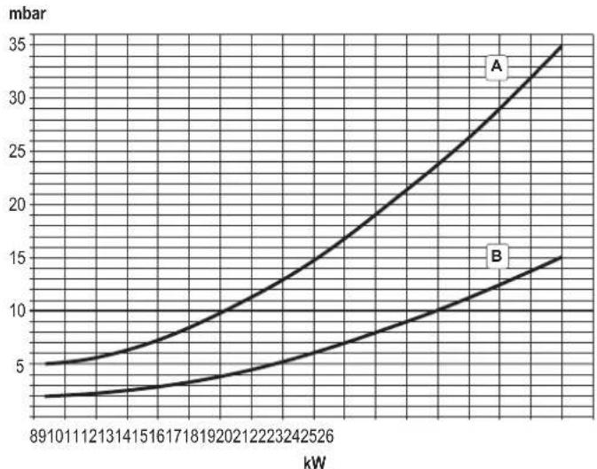
A = LPG - B = NATURAL GAS

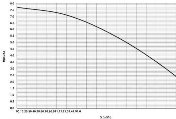
Residual head available for system DIVAtech D LN C24
A = Boiler pressure losses - 1, 2 and 3 = Circulating pump speed
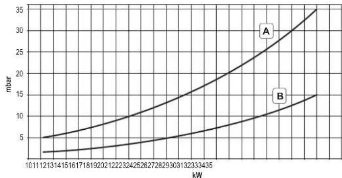
Pressure - power diagrams DIVAtech D LN C30
A = LPG - B = NATURAL GAS
Residual head available for system DIVAtech D LN C30
A = Boiler pressure losses - 1, 2 and 3 = Circulating pump speed
5.6 Wiring diagram
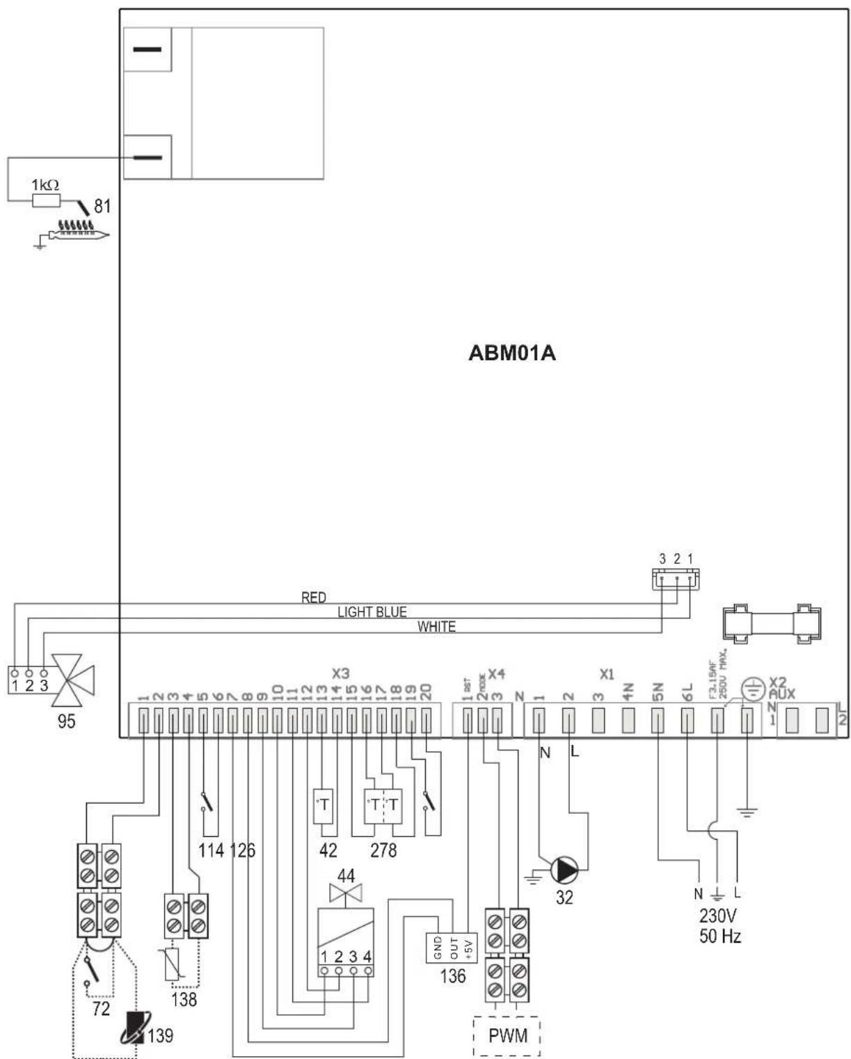
fig. 23-Wiring diagram

Attention: Remove the jumper on the terminal block before connecting the room thermostat or the remote timer control.
32 Heating circulating pump
42 DHW temperature sensor
44 Gas valve
72 Room thermostat (optional)
81 Ignition/detection electrode
95 Diverter valve
114 Water pressure switch
126 Fume thermostat
136 Flowmeter
138 External probe (optional)
139 Remote timer control (optional)
278 Double sensor (Safety + heating)
FR
1. GENÉRALITÉS
Selection Eco/Comfort
Vidange installation
3.4 Raccordement gaz
Pi maxi 65 mbar24 Vdc-class
Activation du mode TEST
MODELE: DIVATECH D LN C30 - (ODCC6YWA)

- DIVAtech D LN C24/C32
- IT
- AVVERTENZE GENERALI
- OPERATING INSTRUCTIONS
- Introduction
- Control panel
- Key of panel fig. 1
- Indication during operation
- Heating
- Domestic hot water (DHW)
- Comfort
- Fault
- Lighting and shutdown
- Connection to the power supply
- Turning the boiler off and on
- Adjustments
- Summer/Winter Sustainover
- Heating temperature adjustment
- DHW temperature adjustment
- Room temperature adjustment (with optional room thermostat)
- Room temperature adjustment (with optional remote timer control)
- ECO/COMFORT selection
- Sliding Temperature
- Adjustments from Remote Timer Control
- System water pressure adjustment
- System draining
- INSTALLATION
- General Instructions
- Place of installation
- Plumbing connections
- Important
- Water system characteristics
- Antifreeze system, antifreeze fluids, additives and inhibitors
- Gas connection
- Electrical connections
- Room thermostat (optional)
- Accessing the electrical terminal block
- Air/fume ducts
- SERVICE AND MAINTENANCE
- Adjustments
- Gas conversion
- ALL COMPONENTS DAMAGED DURING CONVERSION OPERATIONS MUST BE REPLACED.
- Activation of Auto-setting function for gas valve calibration
- THIS PROCEDURE MUST ONLY BE CARRIED OUT IN THE FOLLOWING CASES: GAS VALVE REPLACEMENT, CARD REPLACEMENT, CONVERSION FOR GAS CHANGE.
- Gas valve pre-calibration
- Gas valve calibration
- Checking of gas pressure values and adjustment with limited range
- TEST mode activation
- Heating power adjustment
- Configuration Menu
- Notes:
- Service menu
- “tS”-Transparent Parameters Menu
- "In" - Information Menu
- "Hi" - History Menu
- "rE"-History Reset
- Commissioning
- Before lighting the boller
- IF THE ABOVE INSTRUCTIONS ARE NOT OBSERVED THERE MAY BE RISK OF SUFFOCATION OR POISONING DUE TO GAS OR FUMES ESCAPING; DANGER OF FIRE OR EXPLOSION. ALSO, THERE MAY BE A RISK OF ELECTRIC SHOCK OR FLOODING THE ROOM.
- Checks during operation
- Maintenance
- Periodical inspection
- Troubleshooting
- Diagnostics
- List of faults
- TECHNICAL DATA AND CHARACTERISTICS
- ErP product fiche
- Diagrams
- FR
- GENÉRALITÉS
- Selection Eco/Comfort
- Vidange installation
- Raccordement gaz
- Activation du mode TEST
Brand : FERROLI
Model : DIVAtech D LN C24
Category : Central heating boiler