
Divatech D - Central heating boiler FERROLI - Free user manual and instructions
Find the device manual for free Divatech D FERROLI in PDF.
| Brand | Ferroli |
| Model | Divatech D (HF24 / HF32) |
| Product type | Sealed chamber central heating boiler, very high efficiency |
| Weight (empty) | HF24: 32 kg / HF32: 35 kg |
| Power supply | 230 V / 50 Hz |
| Power consumption | HF24: 110 W / HF32: 135 W |
| Compatible gas | Natural gas (G20) or LPG (G31) |
| Gas supply pressure | G20: 20 mbar / G31: 37 mbar |
| Heating temperature range | 30 °C to 80 °C (recommended between 45 and 80 °C) |
| Domestic hot water temperature range | 40 °C to 55 °C |
| Installation hydraulic pressure | About 1 bar (minimum 0.8 bar) |
| Maximum heating pressure | 3 bar |
| Protection rating | IP X5D |
| Main functions | Central heating and domestic hot water production (external tank option), summer/winter mode, adaptive temperature with outdoor sensor, Eco/Comfort mode, self-diagnosis with error codes |
| Maintenance | Annual by a qualified professional: safety checks, burner and heat exchanger cleaning, pressure and tightness verification |
| Safety devices | Safety valve, water pressure switch, frost protection, self-diagnosis, safety shutdown in case of anomaly |
| Spare parts and repairability | Use only original parts. Repair by a qualified professional. |
| Expansion vessel | HF24: 8 litres / HF32: 10 litres, precharge pressure 1 bar |
| Maximum thermal output | HF24: 25.8 kW / HF32: 34.4 kW |
| Efficiency at maximum power | HF24: 93.0% / HF32: 93.1% |
| NOx emission class | 3 (< 150 mg/kWh) |
Frequently Asked Questions - Divatech D FERROLI
User questions about Divatech D FERROLI
0 question about this device. Answer the ones you know or ask your own.
Ask a new question about this device
Download the instructions for your Central heating boiler in PDF format for free! Find your manual Divatech D - FERROLI and take your electronic device back in hand. On this page are published all the documents necessary for the use of your device. Divatech D by FERROLI.
USER MANUAL Divatech D FERROLI
DIVAtech D HF24/HF32

C E
RU TEXHnueCKN IACNOPT N3dEJIY
PukOBoCTBO NO 3KcIpyATAUIN,MOHTAXUYTEXO6CJyXBAHIO
EAC
IT
1. AVVERTENZE GENERALI
-
outweighs the costs of developing and maintaining a new technology, such as the use of a variety of different technologies.
-
atraverso ilNumero Verde 800 59 60 40.
- Read the warnings in this instruction booklet carefully since they provide important information on safe installation, use and maintenance.
- This instruction booklet is an integral and essential part of the product and must be kept with care by the user for future reference.
- If the unit is sold or transferred to another owner or if it is to be moved, always make sure the booklet stays with the boiler so that it can be consulted by the new owner and/or installer.
- Installation and maintenance must be carried out by professionally qualified personnel, according to current regulations and the manufacturer's instructions.
- Incorrect installation or inadequate maintenance can result in damage or injury. The manufacturer declines any liability for damage caused by errors in installation and use or by failure to follow the instructions provided.
- Before carrying out any cleaning or maintenance operation, disconnect the unit from the power supply using the system switch and/or the special cut-off devices.
- In case of a fault and/or poor operation, deactivate the unit and do not try to repair it or directly intervene. Contact professionally qualified personnel. Any repair/replacement of the products must only be carried out by qualified personnel using genuine parts. Failure to comply with the above can compromise the safety of the unit.
Periodic maintenance performed by qualified personnel is essential in order to ensure proper operation of the unit. - This unit must only be used for its intended purpose. Any other use is deemed improper and therefore hazardous.
- After unpacking, check the good condition of the contents. The packing materials are potentially hazardous and must not be left within the reach of children.
- The unit can be used by children aged at least 8 years and by persons with reduced physical, sensory or mental capabilities, or lacking experience or the necessary knowledge, only if under supervision or they have received instructions on its safe use and the related risks. Children must not play with the unit. Cleaning and maintenance intended to be done by the user can be carried out by children aged at least 8 years only if under supervision.
- In case of doubt, do not use the unit. Contact the supplier.
- The unit and its accessories must be appropriately disposed of in compliance with current regulations.
- The images given in this manual are a simplified representation of the product. In this representation there may be slight and insignificant differences with respect to the product supplied.
CE THE CE MARKING CERTIFIES THAT THE PRODUCTS MEET THE ESSENTIAL REQUIREMENTS OF THE RELEVANT DIRECTIVES IN FORCE. THE DECLARATION OF CONFORMITY MAY BE REQUESTED FROM THE MANUFACTURER.
2. OPERATING INSTRUCTIONS
2.1 Introduction
Dear Customer,
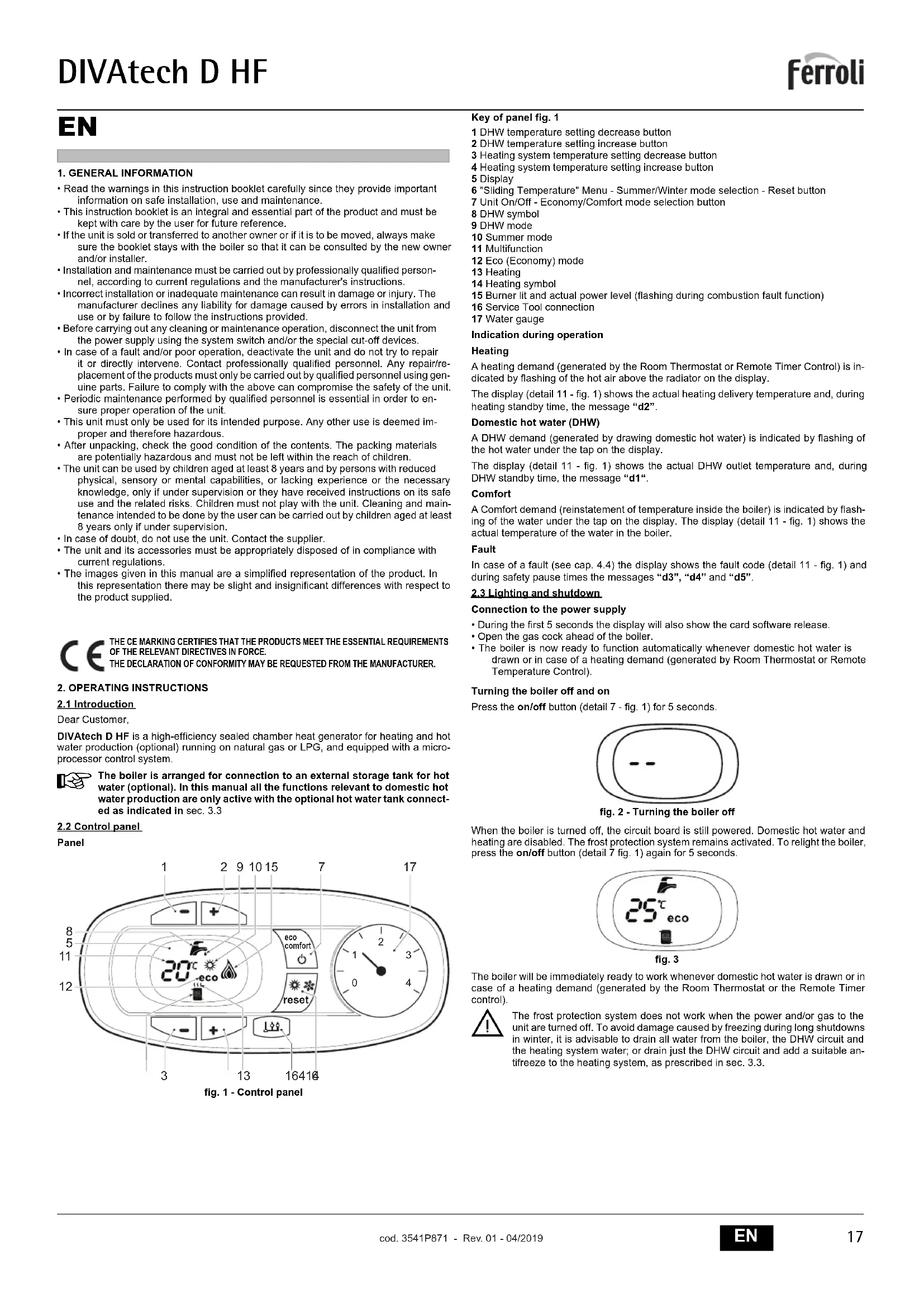
DIVatech D HF is a high-efficiency sealed chamber heat generator for heating and hot water production (optional) running on natural gas or LPG, and equipped with a microprocessor control system.
The boiler is arranged for connection to an external storage tank for hot water (optional). In this manual all the functions relevant to domestic hot water production are only active with the optional hot water tank connected as indicated in sec. 3.3
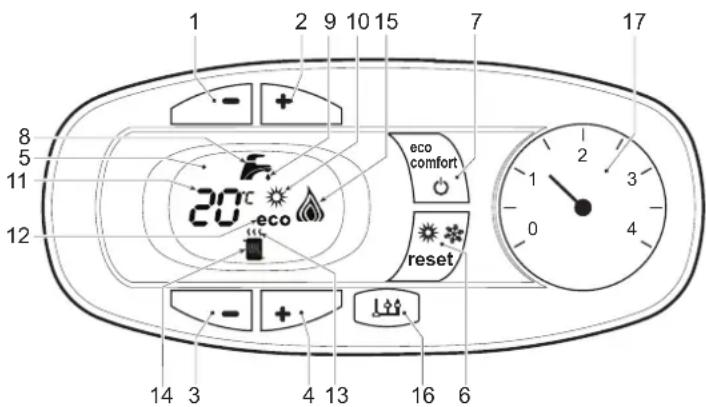
2.2 Control panel
Panel
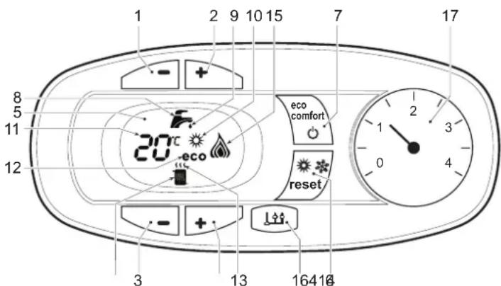
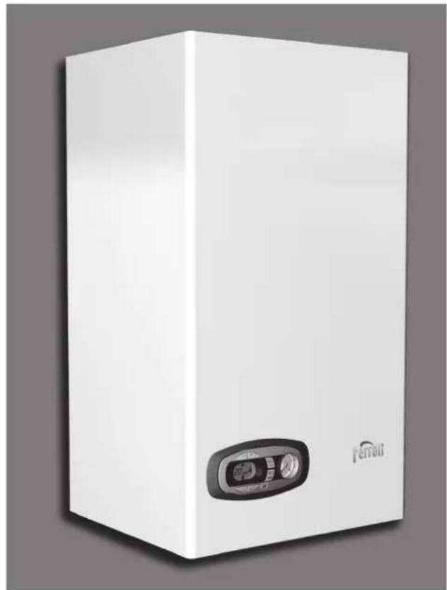
fig. 1 - Control panel
Key of panel fig. 1
1 DHW temperature setting decrease button
2 DHW temperature setting increase button
3 Heating system temperature setting decrease button
4 Heating system temperature setting increase button
5 Display
6 "Sliding Temperature" Menu - Summer/Winter mode selection - Reset button
7 Unit On/Off - Economy/Comfort mode selection button
8 DHW symbol
9 DHW mode
10 Summer mode
11 Multifunction
12 Eco (Economy) mode
13 Heating
14 Heating symbol
15 Burner lit and actual power level (flashing during combustion fault function)
16 Service Tool connection
17 Water gauge
Indication during operation
Heating
A heating demand (generated by the Room Thermostat or Remote Timer Control) is indicated by flashing of the hot air above the radiator on the display.
The display (detail 11 - fig. 1) shows the actual heating delivery temperature and, during heating standby time, the message "d2".
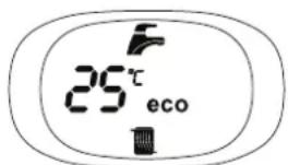
Domestic hot water (DHW)
A DHW demand (generated by drawing domestic hot water) is indicated by flashing of the hot water under the tap on the display.
The display (detail 11 - fig. 1) shows the actual DHW outlet temperature and, during DHW standby time, the message "d1".
Comfort
A Comfort demand (reinstatement of temperature inside the boiler) is indicated by flashing of the water under the tap on the display. The display (detail 11 - fig. 1) shows the actual temperature of the water in the boiler.
Fault
In case of a fault (see cap. 4.4) the display shows the fault code (detail 11 - fig. 1) and during safely pause times the messages "d3", "d4" and "d5".
2.3 Lighting and shutdown
Connection to the power supply
- During the first 5 seconds the display will also show the card software release.
- Open the gas cock ahead of the boiler.
- The boiler is now ready to function automatically whenever domestic hot water is drawn or in case of a heating demand (generated by Room Thermostat or Remote Temperature Control).
Turning the boiler off and on
Press the on/off button (detail 7 - fig. 1) for 5 seconds.

fig.2-Turning the boiler off
When the boiler is turned off, the circuit board is still powered. Domestic hot water and heating are disabled. The frost protection system remains activated. To relight the boiler, press the on/off button (detail 7 fig. 1) again for 5 seconds.
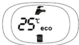
fig. 3
The boiler will be immediately ready to work whenever domestic hot water is drawn or in case of a heating demand (generated by the Room Thermostat or the Remote Timer control).

The frost protection system does not work when the power and/or gas to the unit are turned off. To avoid damage caused by freezing during long shutdowns in winter, it is advisable to drain all water from the boiler, the DHW circuit and the heating system water; or drain just the DHW circuit and add a suitable antifreeze to the heating system, as prescribed in sec. 3.3.
2.4 Adjustments
Summer/Winter Swithchover
Press the summer/winter button (detail 6 - fig. 1) for 2 seconds.
The display activates the Summer symbol (detail 10 - fig. 1): the boiler will only deliver domestic hot water. The antifreeze system remains activated.
To deactivate the Summer mode, press the summer/winter button (detail 6 - fig. 1) again for 2 seconds.
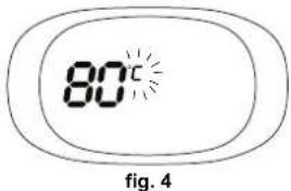
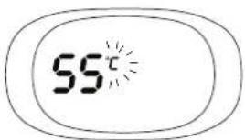
Heating temperature adjustment
Use the heating buttons (details 3 and 4 - fig. 1) to adjust the temperature from a min. of 30^ to a max. of 80^ ; in any case, it is advisable not to operate the boiler below 45^ .
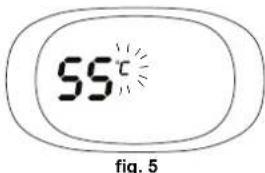
DHW temperature adjustment
Use the DHW buttons (details 1 and 2 - fig. 1) to adjust the temperature from a min. of 40^ to a max. of 55^ .
Room temperature adjustment (with optional room thermostat)
Using the room thermostat, set the temperature required in the rooms. If the room thermostat is not installed, the boiler will keep the system at the set system delivery setpoint temperature.
Room temperature adjustment (with optional remote timer control)
Using the remote timer control, set the required temperature in the rooms. The boiler will adjust the system water according to the required room temperature. For operation with remote timer control, please refer to the relevant instruction manual.
ECO/COMFORT selection
The unit has a function that ensures a high domestic hot water delivery speed and maximum comfort for the user. When the device is activated (COMFORT mode), the water contained in the boiler is kept hot, thereby ensuring immediate availability of hot water on opening the tap, without waiting times.
The user can deactivate the device (ECO mode) by pressing the eco/comfort button (detail 7 - fig. 1). In ECO mode the display activates the ECO symbol (detail 12 - fig. 1). To activate the COMFORT mode, press the eco/comfort button (detail 7 - fig. 1) again.
Sliding Temperature
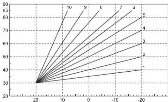
When the optional external probe is installed the boiler adjustment system works with "Sliding Temperature". In this mode, the heating system temperature is regulated according to weather conditions, to ensure the high comfort and energy efficiency throughout the year. In particular, as the outside temperature increases the system delivery temperature decreases according to a specific "compensation curve".
With the Sliding Temperature adjustment, the temperature set with the heating buttons (detail 3 - fig. 1) becomes the maximum system delivery temperature. It is advisable to set a maximum value to allow system adjustment throughout its useful operating range.
The boiler must be adjusted at the time of installation by qualified personnel. However, the user can make any further adjustments necessary to optimise comfort levels.
Compensation curve and curve offset
Press the reset button (detail 6 - fig. 1) for 5 seconds to access the "Sliding temperature" menu; the display shows "CU" flashing.
Use the DHW buttons (detail 1 - fig. 1) to adjust the desired curve from 1 to 10 according to the characteristic (fig. 6). By setting the curve to 0, the sliding temperature adjustment is disabled.
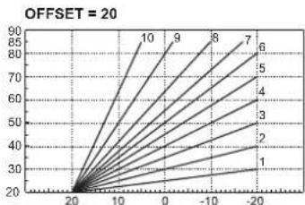
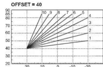
Press the heating buttons (detail 3 - fig. 1) to access parallel curve offset; the display shows "OF" flashing. Use the DHW buttons (detail 1 - fig. 1) to adjust parallel curve offset according to the characteristic (fig. 7).
Press the reset button (detail 6 - fig. 1) again for 5 seconds to exit the "Sliding Temperature" menu.
If the room temperature is lower than the required value, it is advisable to set a higher order curve and vice versa. Proceed by increasing or decreasing in steps of one and check the result in the room.
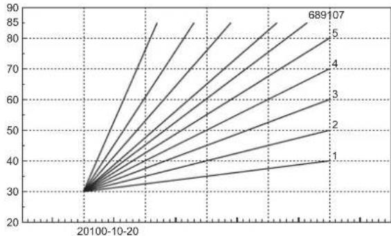
fig. 6 - Compensation curves
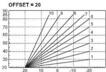
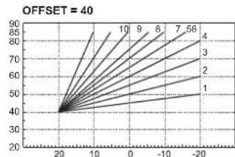
fig. 7 - Example of compensation parallel curve offset
Adjustments from Remote Timer Control

If the Remote Timer Control (optional) is connected to the boiler, the above adjustments are managed according to that given in table 1.
Table.1
| Heating temperature setting | Adjustment can be made from the Remote Timer Control menu and the boiler control panel. |
| DHW temperature adjustment | Adjustment can be made from the Remote Timer Control menu and the boiler control panel. |
| Summer/Winter Switchover | Summer mode has priority over a possible Remote Timer Control heating demand. |
| Eco/Comfort selection | On disabling DHW from the Remote Timer Control menu, the boiler selects the Economy mode. In this condition, the eco/comfort button (detail 7 - fig. 1) on the boiler panel is disabled. |
| On enabling DHW from the Remote Timer Control menu, the boiler selects the Comfort mode. In this condition it is possible select one of the two modes with the eco/comfort button (detail 7 - fig. 1) on the boiler panel. | |
| Sliding Temperature | Both the Remote Timer Control and the boiler card manage Sliding Temperature adjustment: the boiler card Sliding Temperature has priority. |
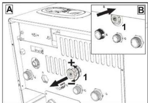
System water pressure adjustment
The filling pressure read on the boiler water gauge (detail 2 - fig. 8) with system cold must be approx 1.0 bar. If the system pressure falls below minimum values, the boiler stops and fault F37 is displayed. Pull out the filling knob (detail 1 - fig. 8) and turn it anticlockwise to return it to the initial value. Always close it afterwards.
Once the system pressure is restored, the boiler will activate the 300-second air venting cycle indicated on the display by Fh.
To prevent boiler shutdown, it is advisable to periodically check the pressure on the gauge with system cold. In case of a pressure below 0.8 bar, it is advisable to restore it.
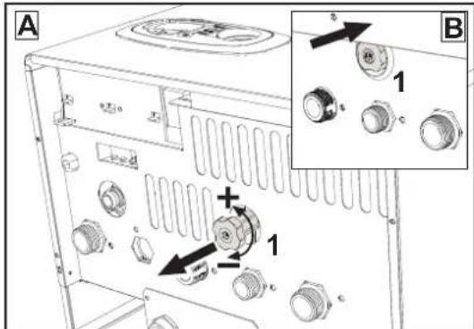
fig. 8-Filling knob
System draining
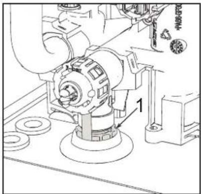
The drain faucet ring nut is located under the safety valve inside the boiler.
To drain the system, turn the ring (ref. 1 - fig. 9) counter-clockwise to open the faucet. Do not use any tools; use hands only.
To drain only the water in the boiler, first close the shut-off valves between the system and boiler before turning the ring.
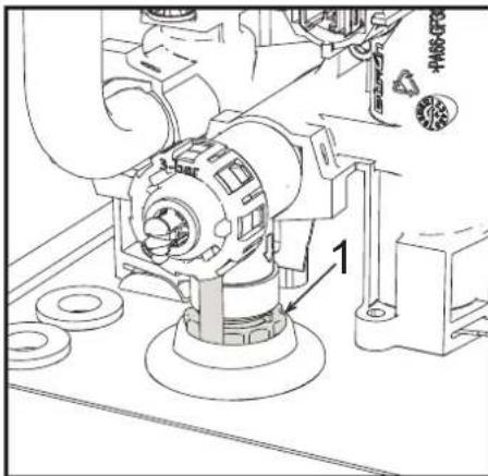
fig. 9-Safety valve with drain faucet
3. INSTALLATION
3.1 General Instructions
BOILER INSTALLATION MUST ONLY BE PERFORMED BY QUALIFIED PERSONNEL, IN ACCORDANCE WITH ALL THE INSTRUCTIONS GIVEN IN THIS TECHNICAL MANUAL, THE PROVISIONS OF CURRENT LAW, THE PRESCRIPTIONS OF NATIONAL AND LOCAL STANDARDS AND THE RULES OF PROPER WORKMANSHIP.
3.2 Place of installation

The combustion circuit is sealed with respect to the place of installation and therefore the unit can be installed in any room except in a garage. The place of installation must be sufficiently ventilated to prevent the creation of dangerous conditions in case of even small gas leaks. Otherwise there may be a risk of suffocation and intoxication or explosion and fire. This safety precaution is required by EEC Directive No. 2009/142 for all gas units, including so-called sealed chamber units.
The unit is designed to operate in a partially protected place, with a minimum temperature of -5^ . If provided with the special antifreeze kit, it can be used with a minimum temperature down to -15^ . The boiler must be installed in a sheltered place, for instance under the slope of a roof, inside a balcony or in a protected recess.
The place of installation must be free of flammable materials, objects and dusts or corrosive gases.
The boiler is arranged for wall mounting and comes as standard with a hooking bracket. Wall fixing must ensure stable and effective support for the generator.

If the unit is enclosed in a cabinet or mounted alongside, there must be sufficient space for removing the casing and for normal maintenance activities
3.3 Plumbing connections
Important

The safety valve outlet must be connected to a funnel or collection pipe to prevent water spurting onto the floor in case of overpressure in the heating circuit. Otherwise, if the discharge valve cuts in and floods the room, the boiler manufacturer cannot be held liable.

Before making the connection, check that the unit is arranged for operation with the type of fuel available and carefully clean all the system pipes.
Carry out the relevant connections according to the diagram in fig. 25 and the symbols on the unit.
Note: The unit is equipped with an internal bypass in the heating circuit.
Water system characteristics
In the presence of water harder than 25^ (1^ = 10ppmCaCO_3) use suitably treated water in order to avoid possible scaling in the boiler.
Antifreeze system, antifreeze fluids, additives and inhibitors
When necessary, antifreeze fluids, additives and inhibitors can be used only if the manufacturer of such fluids or additives guarantees that they are suitable and do not cause damage to the exchanger or other components and/or materials of the boiler and system. Do not use generic antifreeze fluids, additives or inhibitors that are not specific for use in heating systems and compatible with the materials of the boiler and system.
Connection to a storage tank for domestic hot water
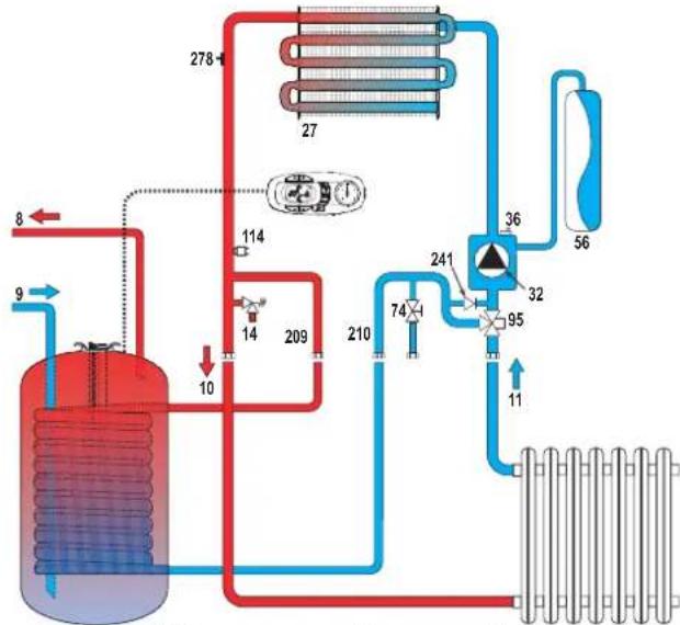
The unit's electronic card is arranged for managing an external storage tank for domestic hot water production. Carry out the plumbing connections according to the diagram of fig. 10. Carry out the electrical connections as shown on the wiring diagram in fig. 30. It is necessary to use the kit code 1KWMA11W. At the next lighting, the boiler control system detects the hot water tank probe and automatically configures the DHW function, activating the display and relevant controls.
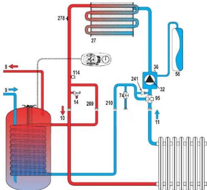
Fig. 10-Diagram of connection to an external hot water tank
8 Domestic hot water outlet
9 Cold water inlet
10 System delivery - 0 3/4"
11 System return - 0 3/4
95 Diverter valve
209 Hot water tank delivery - 0 3/4"
210 Hot water tank return - 0 3/4
3.4 Gas connection
The gas must be connected to the relevant connection (see fig. 25) in conformity with the current standards, using a rigid metal pipe or a continuous surface flexible s/steel tube and installing a gas cock between the system and boiler. Make sure all the gas connections are tight.
3.5 Electrical connections
IMPORTANT

BEFORE CARRYING OUT ANY OPERATION THAT REQUIRES REMOVING THE CASING, DISCONNECT THE BOILER FROM THE ELECTRIC MAINS WITH THE MAIN SWITCH.
NEVER TOUCH THE ELECTRICAL COMPONENTS OR CONTACTS WITH THE MAIN SWITCH TURNOED ONI DANGER OF ELECTRIC SHOCK WITH RISK OF INJURY OR DEATH!

The unit must be connected to an efficient grounding system in accordance with applicable safety regulations. Have the efficiency and suitability of the grounding system checked by professionally qualified personnel; the Manufacturer declines any liability for damage caused by failure to earth the system.
The boiler is prewired and provided with a three-pole cable, without a plug, for connection to the electric line. The connections to the grid must be made with a permanent connection and equipped with a bipolar switch whose contacts have a minimum opening of at least 3mm , interposing fuses of max. 3A between the boiler and the line. Make sure to respect the polarities (LINE: brown wire / NEUTRAL: blue wire / GROUND: yellow-green wire) in the connections to the electric line.

The unit's supply cable MUST NOT BE REPLACED BY THE USER. If the cable gets damaged, turn the unit off and have the cable replaced only by professionally qualified personnel. In case of replacement, only use cable "HAR H05 VV-F" 3x0.75 mm2 with max. external diameter of 8 mm.
Room thermostat (optional)

IMPORTANT: THE ROOM THERMOSTAT MUST HAVE VOLTAGE-FREE CONTACTS. CONNECTING 230 V TO THE ROOM THERMOSTAT TERMINALS WILL PERMANENTLY DAMAGE THE ELECTRONIC BOARD.
When connecting time controls or a timer, do not take the power supply for these devices from their breaking contacts Their power supply must be by means of direct connection from the mains or with batteries, depending on the kind of device.
Accessing the electrical terminal block
The electrical terminal block can be accessed after removing the casing. The layout of the terminals for the various connections is given in the wiring diagram in fig. 30.
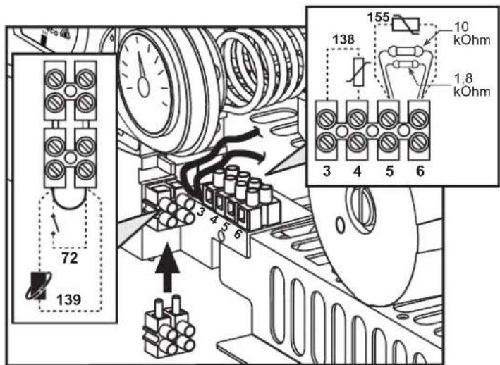
fig. 11- Accessing the terminal block
3.6 Fume ducts
Important
The unit is a "C type" with sealed chamber and forced draught, the air inlet and fume outlet must be connected to one of the following extraction/suction systems. The unit is approved for operation with all the Cny flue configurations given on the dataplate. Some configurations may be expressly limited or not permitted by law, standards or local regulations. Before installation, check and carefully follow the instructions. Also, comply with the instructions on the positioning of wall and/or roof terminals and the minimum distances from windows, walls, ventilation openings, etc.
Baffles
Boiler operation requires fitting the baffles supplied with the unit. Make sure boiler is properly fitted with the correct baffle (if to be used).
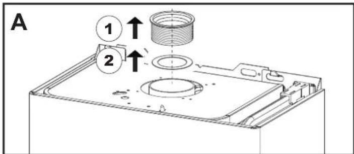
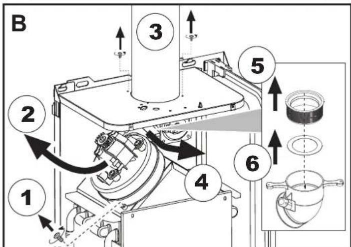
A Baffle replacement with boiler not installed
B Baffle replacement with boiler and fume ducts already installed
Connection with coaxial pipes
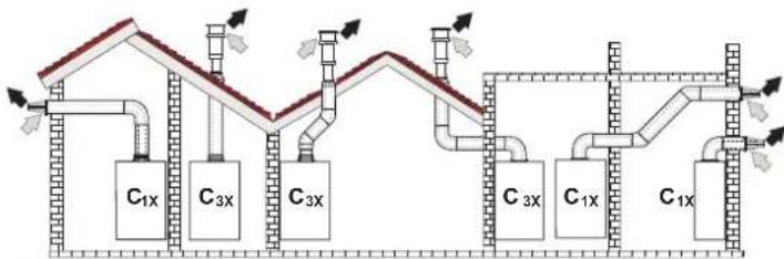
fig. 12 - Examples of connection with coaxial pipes (Air / Fumes)
Table. 2 - Typology
| Type | Description |
| C1X | Wall horizontal exhaust and inlet |
| C3X | Roof vertical exhaust and inlet |
For coaxial connection, fit the unit with one of the following starting accessories. For the wall hole dimensions, refer to the figure on the cover.
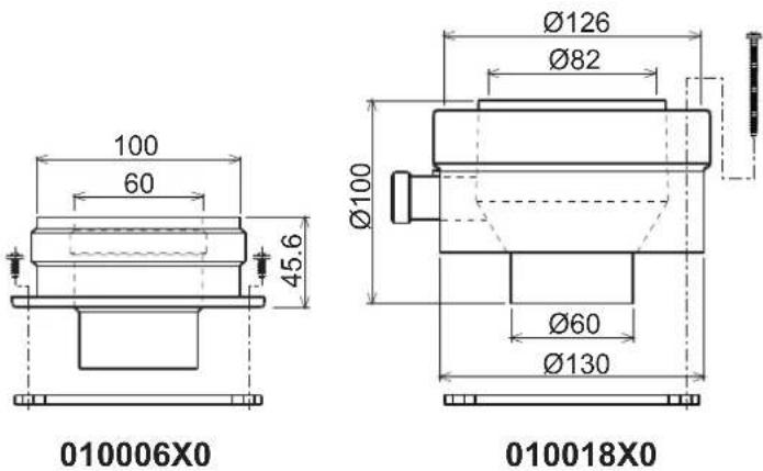
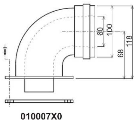
fig. 13 - Starting accessory for coaxial ducts
Table. 3- Baffles for coaxial ducts
| Coaxial 60/100 | Coaxial 80/125 | |||
| Max. permissible length | DIVAtech D HF24 = 5 mDIVAtech D HF32 = 5 m | 10 m | ||
| Reduction factor 90° bend | 1 m | 0.5 m | ||
| Reduction factor 45° bend | 0.5 m | 0.25 m | ||
| Baffle to use | 0÷2 m | DIVAtech D HF24 = Ø43DIVAtech D HF32 = Ø45 | 0÷3 m | DIVAtech D HF24 = Ø43DIVAtech D HF32 = Ø45 |
| 2÷5 m | no baffle | 3÷10 m | no baffle | |
Connection with separate pipes
fig. 14 - Examples of connection with separate pipes (E Air / = Figures)
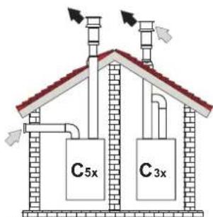
Table. 4 - Typology
| Type Description | |
| C1X | Wall horizontal exhaust and intake. The inlet/outlet terminals must be concentric or close enough to be undergo similar wind conditions (within 50 cm) |
| C3X | Roof vertical exhaust and intake. Inlet/outlet terminals like for C12 |
| C5X | Wall or roof exhaust and intake separate or in any case in areas with different pressures. The exhaust and intake must not be positioned on opposite walls. |
| C6X | Intake and exhaust with separately certified pipes (EN 1856/1) |
| B2X | Intake from installation room and wall or roof exhaustIMPORTANT - THE ROOM MUST BE PROVIDED WITH APPROPRIATE VENTILATION |
For the connection of separate ducts, fit the unit with the following starting accessory:
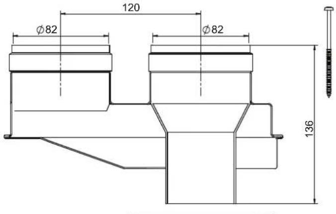
fig. 15 - Starting accessory for separate ducts code 010031X0
Before installation, check the baffle to use and that the maximum permissible length is not exceeded, by means of a simple calculation:
- Establish the layout of the system of split flues, including accessories and outlet terminals.
- Consult table 6 and identify the losses in m eq (equivalent meters) of every component, according to the installation position.
- Check that the sum total of losses is less than or equal to the maximum permissible length in table 5.
Table. 5- Baffles for separate ducts
| DIVAtech D HF24 DIVAtech D HF32 | ||||
| Max. permissible length | 60 m_eq | 48 m_eq | ||
| Baffle to use | 0 - 20 m_eq | Ø 430 - 15 m | eq | Ø 45 |
| 20 - 45 m_eq | Ø 47 15 - 35 | eq | Ø 50 | |
| 45 - 60 m_eq | No baffle 35 - 48 m | eq | No baffle | |
Table. 6 - Accessories
| Losses in meq | ||||
| Air inlet | Fume exhaust | |||
| Vertical Horizontal | ||||
| Ø 80 | PIPE | 0.5 m M/F 1KWMA38A 0.5 0.5 | 1.0 | |
| 1 m M/F 1KWMA83A 1.0 1.0 | 2.0 | |||
| 2 m M/F 1KWMA06K 2.0 2.0 | 4.0 | |||
| BEND | 45° F/F | 1KWMA01K 1.9 | 2.9 | |
| 45° M/F | 1KWMA65A 1.9 | 2.9 | ||
| 90° F/F | 1KWMA02K 2.0 | 3.0 | ||
| 90° M/F | 1KWMA82A 1.5 | 2.5 | ||
| 90° M/F + Test point | 1KWMA70U | 1.5 | ||
| PIPE SECTION | with test point | 1KWMA16U | 0.2 | |
| for condensate drain | 1KWMA55U | - | ||
| TEE | for condensate drain | 1KWMA05K | - | |
| TERMINAL | air, wall | 1KWMA85A 2.0 | - | |
| fumes, wall with antiwind | 1KWMA86A | - | ||
| FLUE | Split air/fumes 80/80 | 1KWMA84U | - | |
| Fume outlet only Ø80 | 1KWMA83U + 1KWMA86U | - | ||
| Ø 100 | REDUCTION | from Ø80 to Ø100 | 1KWMA03U | 0.0 |
| from Ø100 to Ø80 | 1.5 | |||
| PIPE | 1 m M/F 1KWMA08K 0.4 0.4 | 0.8 | ||
| BEND | 45° M/F | 1KWMA03K 0.6 | 1.0 | |
| 90° M/F | 1KWMA04K 0.8 | 1.3 | ||
| TERMINAL | air, wall | 1KWMA14K 1.5 | - | |
| fumes, wall with antiwind | 1KWMA29K | - | ||
| fumes, wall with antiwind | 1KWMA29K | - | ||
| Ø 60 | PIPE | 1 m M/F 010028X0 | - | 2.0 6.0 |
| BEND | 90° M/F | 010029X0 | - | |
| REDUCTION | 80 - 60 | 010030X0 | - | |
| TERMINAL | fumes, wall | 1KWMA90A | - | |
| ATTENTION: CONSIDER THE HIGH PRESSURE LOSSES OF Ø60 ACCESSORIES; USE THEM ONLY IF NECESSARY AND AT THE LAST FUME EXHAUST SECTION. | ||||
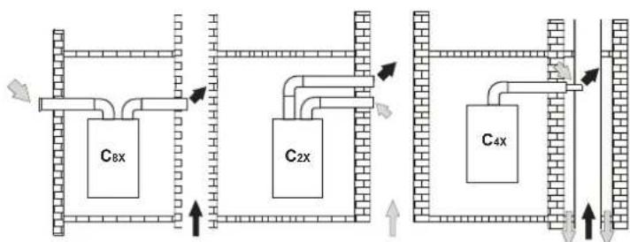
Connection to collective flues
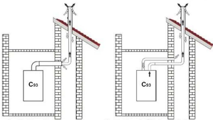
fig. 16 - Examples of connection to collective flues (Air / Flues)
Table. 7 - Typology
| Type | Description |
| C2X | Intake and exhaust in common flue (intake and exhaust in same flue) |
| C4X | Intake and exhaust in common and separate flues, but undergoing similar wind conditions |
| C8X | Exhaust in single or common flue and wall intake |
| B3X | Intake from installation room by means of concentric duct (that encloses the exhaust) and exhaust in common flue with natural draught IMPORTANT- THE ROOM MUST BE PROVIDED WITH APPROPRIATE VENTILATION |
| C93 | Exhaust to a vertical terminal and intake from existing flue. |
If the boiler is to be connected DIVAtech D HF to a collective flue or to a single flue with natural draught, the flue or chimney must be expressly designed by professionally qualified technical personnel in conformity with the current regulations and be suitable for sealed chamber units equipped with fan.
4. SERVICE AND MAINTENANCE
Important

All adjustment, conversion, commissioning and maintenance operations described below must only be carried out by Qualified Personnel (meeting the professional technical requirements of current regulations) such as the personnel of the Local After-Sales Technical Service.
FERROLI declines any liability for damage and/or injury caused by unqualified and unauthorized persons tampering with the unit.
4.1 Adjustments
Gas conversion

ALL COMPONENTS DAMAGED DURING CONVERSION OPERATIONS MUST BE REPLACED.
The unit can operate on natural gas or LPG and is factory-set for use with one of these two gases, as clearly shown on the packing and on the data plate. Whenever a gas different from that for which the unit is arranged has to be used, the special conversion kit will be required, proceeding as follows:
- Disconnect the boiler power supply and close the gas cock.
- Replace the nozzles at the main burner, fitting the nozzles specified in the technical data table in cap. 5, according to the type of gas used
- Switch the boiler power on and open the gas cock.
-
Modify the parameter for the type of gas:
-
put the boiler in standby mode
- press the DHW buttons details 1 and 2 - fig. 1 for 10 seconds: the display shows "b01" flashing.
- press the DHW buttons details 1 and 2 - fig. 1 to set the parameter 00 (for natural gas operation) or 01 (for LPG operation).
- press the DHW buttons details 1 and 2 - fig. 1 for 10 seconds.
-
the boiler will return to standby mode
-
Adjust the minimum and maximum pressures at the burner (ref. relevant paragraph), setting the values given in the technical data table for the type of gas used
- Apply the sticker contained in the conversion kit, near the data plate as proof of the conversion.
Activation of Auto-setting function for gas valve calibration
THIS PROCEDURE MUST ONLY BE CARRIED OUT IN THE FOLLOWING CASES: GAS VALVE REPLACEMENT, CARD REPLACEMENT, CONVERSION FOR GAS CHANGE.
The B&P Gas Valve (with integrated modulating operator) does not provide for mechanical calibration: the minimum and maximum power adjustments are therefore electronically done via two parameters:
| Contents | Description | Natural Gas | Propane Gas |
| q01 | Absolute minimum current offset 0÷100 0÷150 | ||
| q02 | Absolute maximum current offset | 0÷100 | 0-150 |
Gas valve pre-calibration
- Connect a pressure gauge to monitor the gas valve outlet pressure.
- Enable the Auto-setting function (Parameter b12=1).
- Activate the calibration procedure by pressing the heating + button and Eco/Comfort button together for 5 seconds. The message "Au-to" immediately appears (in two successive flashes) and the burner is lit. Within 8 seconds (natural gas and LPG) the boiler finds the ignition point. The ignition point, absolute minimum current Offset (Parameter q01) and absolute maximum current Offset (Parameter q02) values are stored by the card.
Gas valve calibration
- The display will show "q02" flashing; the modulation current is forced to the pre-calibration value of the absolute maximum current Offset parameter (Parameter q02).
- Press the DHW buttons to adjust the parameter "q02" until the maximum nominal pressure minus 1mbar is reached on the pressure gauge. Wait 10 seconds for the pressure to stabilise.
- Press the DHW "+" button to set the parameter "q02" until the maximum nominal pressure is reached on the pressure gauge. Wait 10 seconds for the pressure to stabilise.
- If the pressure read on the pressure gauge is different from the maximum nominal pressure, proceed in increments of 1 or 2 units of the parameter "02" by pressing the DHW "+" button: after each change, wait 10 seconds for the pressure to stabilise.
- When the pressure read on the pressure gauge is equal to the maximum nominal pressure (the newly calibrated value of the parameter "q02" is automatically saved), press the heating "--" button: the display will show "q01" flashing; the modulation current is forced to the pre-calibration value of the absolute minimum current Offset parameter (Parameter q01).
- Press the DHW buttons to adjust the parameter "q01" until the minimum nominal pressure plus 0.5mbar is reached on the pressure gauge. Wait 10 seconds for the pressure to stabilise.
- Press the DHW "..." button to adjust the parameter "q01" until the minimum nominal pressure is reached on the pressure gauge. Wait 10 seconds for the pressure to stabilise.
-
If the pressure read on the pressure gauge is different from the minimum nominal pressure, proceed in decrements of 1 or 2 units of the parameter "q01" by pressing the DHW "." button: after each change, wait 10 seconds for the pressure to stabilise.
-
When the pressure read on the pressure gauge is equal to the minimum nominal pressure (the newly calibrated value of the parameter "q01" is automatically saved.), recheck both adjustments by pressing the heating buttons and correct them if necessary by repeating the procedure described above.
- The calibration procedure ends automatically after 15 minutes or by pressing the heating "+" and Eco/Comfort buttons together for 5 seconds.
Checking of gas pressure values and adjustment with limited range
- Check that the supply pressure complies with that indicated in the technical data table.
- Connect a suitable pressure gauge to the pressure sampling point "B" located downstream from the gas valve.
- Activate the TEST mode and follow the instructions for checking the gas pressures at maximum power and minimum power (see next par.).
If the maximum and/or minimum nominal pressures read on the pressure gauge are different from those indicated in the technical data table, proceed with the next sequence.
- Press the Eco/Comfort button for 2 seconds to go to the gas valve Calibration with limited range mode.
- The card goes to the setting "q02"; displaying the currently saved value by pressing the DHW buttons.
-
If the maximum pressure read on the pressure gauge is different from the nominal one, proceed in increments/decrements of 1 or 2 units of the parameter "q02" by pressing the DHW buttons: after each change, the value is stored; wait 10 seconds for the pressure to stabilise.
-
Press the heating " - " button (ref. 3 - fig. 1).
-
The card goes to the setting "q01"; displaying the currently saved value by pressing the DHW buttons.
- If the minimum pressure read on the pressure gauge is different from the nominal one, proceed in increments/decrements of 1 or 2 units of the parameter "q01" by pressing the DHW buttons: after each change, the value is stored; wait 10 seconds for the pressure to stabilise.
-
Recheck both settings by pressing the heating buttons and if necessary correct them by repeating the procedure described above.
-
Pressing the Eco/Comfort button for 2 seconds returns to TEST mode.
- D e a c t i v a t e TEST mode (see next par.).
- Disconnect the pressure gauge.
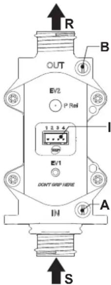
fig.17-Gas valve
A - Upstream pressure point
B-Downstream pressure point
I - Gas valve electrical connection
R-Gas outlet
S-Gas inlet
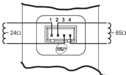
fig. 18 - Gas valve connection
TYPE SGV100
Pimax65mbar
24 Vdc-class B+A
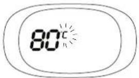
TEST mode activation
Press the heating buttons (details 3 and 4 - fig. 1) together for 5 seconds to activate the TEST mode. The boiler lights at the maximum heating power set as described in the following section.
The heating and DHW symbols (fig. 19) flash on the display; the heating power will appear alongside.
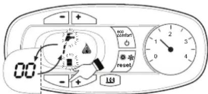
fig. 19 - TEST mode (heating power = 100%)
Press the heating buttons (details 3 and 4 - fig. 1) to increase or decrease the power (Min. = 0%, Max. = 100%).
By pressing the DHW "+" button (detail 1 - fig. 1), boiler output is immediately adjusted to min. (0%) . By pressing the DHW "+" button (detail 2 - fig. 1), boiler output is immediately adjusted to max. (100%) .
If the TEST mode is activated and enough hot water is drawn to activate the DHW mode, the boiler remains in TEST mode but the 3-way valve goes to DHW.
To deactivate the TEST mode, press the heating buttons (details 3 and 4 - fig. 1) together for 5 seconds.
The TEST mode is automatically deactivated in any case after 15 minutes or on stopping of hot water drawing (if enough hot water has been drawn to activate the DHW mode).
Heating power adjustment
To adjust the heating power, switch the boiler to TEST mode (see sec. 4.1). Press the heating buttons detail 3 - fig. 1 to increase or decrease the power (min. = 00 - max. = 100). Press the reset button within 5 seconds and the max. power will remain that just set. Exit TEST mode (see sec. 4.1).
Configuration Menu
The configuration Menu is accessed by pressing the DHW buttons together for 10 seconds. 12 parameters, indicated by the letter "b" and not modifiable from Remote Timer Control, are available.
Press the Heating buttons to scroll the list of parameters in increasing or decreasing order. Press the DHW buttons to view or modify the value of a parameter: the change will be automatically saved.
| Contents Description Range Parameter | |||
| b01 | Gas type selection | 0 = Natural Gas | 0 |
| 1 = LPG | |||
| b02 | Boiler type selection | 1 = Bithermal instantaneous | 3 |
| 2 = Monothermal instantaneous | |||
| 3 = Heating only (3-way valve) | |||
| 4 = Heating only (circulating pump) | |||
| b03 | Combustion chamber type selec-tion | 0 = Sealed Chamber combustion con- trol (without fume pressure switch) | 0 |
| 1 = Open Chamber (with fume thermo-stat) | |||
| 2 = Sealed Chamber (with fume pres-sure switch) | |||
| 3 = Sealed Chamber Combustion con- trol (with fume thermostat on recuperator) | |||
| 4 = LOW NOx Sealed Chamber Com-bustion control (without fume pressure switch) | |||
| 5 = LOW NOx Open Chamber (with fume thermostat) | |||
| b04 | Primary Exchanger type selection 0 | + 13 | 4(for model HF24)5(for model HF32) |
| b05 | Variable output relay operation selection (b02=1) | 0 = External gas valve | NOT AVAILABLE FOR THIS MODEL |
| 1 = System filling solenoid valve | |||
| 2 = Solar 3-way valve | |||
| 3 = Supply indicator with fault present | |||
| 4 = Supply indicator without fault present | |||
| 5 = External circulating pump (during demand and post circulation) | |||
| No effect on adjustment (b02=2) -- | 0 | ||
| No effect on adjustment (b02=3) -- | |||
| No effect on adjustment (b02=4) -- | |||
| b06 | Mains Voltage Frequency | 0 = 50Hz | 0 |
| 1 = 60Hz | |||
| b07 | Comfort burner on time (b02=1) | 0-20 seconds | 5 |
| No effect on adjustment (b02=2) -- | |||
| No effect on adjustment (b02=3) -- | |||
| No effect on adjustment (b02=4) -- | |||
| b08 | Gas valve driver 0 = Standard, 1 0 | ||
| b09 | DHW demand type selection | 0 = Flow switch | 1 |
| 1 = Flowmeter (190 imp/l) | |||
| 2 = Flowmeter (450 imp/l) | |||
| 3 = Flowmeter (700 imp/l) | |||
| b10 | Flowmeter timing (b02=1) | 0 = Deactivated 1 ÷ 10=seconds | 0 |
| Flowmeter timing (b02=2) | 0 = Deactivated 1-10=seconds | ||
| No effect on adjustment (b02=3) -- | |||
| No effect on adjustment (b02=4) -- | |||
| Contents | Description Range Parameter | ||
| b11 | DHW mode activation flow rate (b02=1) | 10 + 100 L/min/10 | |
| DHW mode activation flow rate (b02=2) | 10 + 100 L/min/10 | 15 | |
| No effect on adjustment (b02=3) - | |||
| No effect on adjustment (b02=4) - | |||
| b12 | Enable Auto-Settings procedure | 0 = Disabled1 = Enabled | 0 |
Notes:
- Parameters with more than one description vary their function and/or range in relation to the setting of the parameter given in brackets.
- Parameters with more than one description are reset to the default value if the parameter given in brackets is modified.
To exit the configuration Menu press the DHW buttons together for 10 seconds, or exiting occurs automatically after 2 minutes.
Service menu
The card Service Menu is accessed by pressing the Reset button for 20 seconds. 4 sub-menus are available: press the Heating buttons to select, in increasing or decreasing order, "tS", "In", "Hi" or "rE". "tS" means Transparent Parameters Menu, "In" means Information Menu, "Hi" means History Menu: after selecting the submenu, press the Reset button again to access it; "rE" means History Menu Reset: see description.
“tS” - Transparent Parameters Menu
21 parameters, indicated by the letter "P" are available, which are also modifiable from Remote Timer Control.
Press the Heating buttons to scroll the list of parameters in increasing or decreasing order. Press the DHW buttons to view or modify the value of a parameter: the change will be automatically saved.
| Contents | Description Range | DIVAtech D HF | |
| P01 | Ignition ramp Offset 0-40 | 20 | |
| P02 | Heating ramp 1-20°C/minute | 5 | |
| P03 Heating standby time | 0-10 minutes | 2 | |
| P04 Heating Post-Circulation | 0-20 minutes | 6 | |
| P05 Heating user max. setpoint | 31-85°C | 80 | |
| P06 Max. output in heating | 0-100% | 100 | |
| P07 | Burner shutdown in DHW (b02=1) | 0=Fixed | |
| 1=Linked to setpoint | |||
| 2=Solar | |||
| 3 = DO NOT USE | |||
| 4 = DO NOT USE | |||
| Burner shutdown in DHW (b02=2) | 0=Fixed | 0 | |
| 1=Linked to setpoint | |||
| 2=Solar | |||
| 3 = DO NOT USE | |||
| 4 = DO NOT USE | |||
| Hot water tank hysteresis (b02=3) | 0 (do not use) 1-2-3-4°C | ||
| Hot water tank hysteresis (b02=4) | 0 (do not use) 1-2-3-4°C | ||
| P08 | DHW standby time (b02=1) | 0-60 seconds | 30 |
| DHW standby time (b02=2) | 0-60 seconds | ||
| DHW standby time (b02=3) | 0-60 seconds | ||
| DHW standby time (b02=4) | 0-60 seconds | ||
| P09 | DHW user max. setpoint (b02=1) | 50-65°C | 50 |
| DHW user max. setpoint (b02=2) | 50-65°C | ||
| DHW user max. setpoint (b02=3) | 50-65°C | ||
| DHW user max. setpoint (b02=4) | 50-65°C | ||
| P10 | Anti-inertia function temperature (b02=1) | 5-85°C | |
| No effect on adjustment (b02=2) | -- | 0 | |
| Delivery temperature in DHW (b02=3) | 70-85°C | ||
| Delivery temperature in DHW (b02=4) | 70-85°C | ||
| P11 | Anti-inertia function Post-Circulation (b02=1) | 0-10 Seconds | |
| DHW Post-Circulation (b02=2) | 0-60 Seconds | 30 | |
| DHW Post-Circulation (b02=3) | 0-60 Seconds | ||
| DHW Post-Circulation (b02=4) | 0-60 Seconds | ||
| P12 | Max. output in DHW | 0-100% | 100 |
| P13 | Absolute min. power | 0-100% | 0 |
| P14 | Post-Ventilation | 0=Default | 0 |
| 1=50 seconds | |||
| Contents | Description | Range | DIVAtech D HF |
| P15 | CO2 limit Offset (b03=0) | 0 (Minimum)30 (Maximum) | 20 |
| No effect on adjustment (b03=1) - | |||
| No effect on adjustment (b03=2) - | |||
| CO2 limit Offset (b03=3) | 0 (Minimum)30 (Maximum) | ||
| CO2 limit Offset (b03=4) | 0 (Minimum)30 (Maximum) | ||
| No effect on adjustment (b03=5) - | |||
| P16 | Exchanger protection activation | 0=No F43 | 10 |
| 1-15=1-15°C/second | |||
| P17 | Modulating pump max. speed - absolute Operating | at 100%.Adjustable with optional cable. | 100 |
| P18 | Modulating pump max. speed - post circulation 0-100% not operating.Always at 100% in this model | 60 | |
| P19 | Solar deactivation temperature (b02=1) 0+20°C | 10 | |
| Solar deactivation temperature (b02=2) 0+20°C | |||
| No effect on adjustment (b02=3) - | |||
| No effect on adjustment (b02=4) - | |||
| P20 | Solar ignition temperature (b02=1) 0+20°C | 10 | |
| Solar ignition temperature (b02=2) 0+20°C | |||
| No effect on adjustment (b02=3) - | |||
| No effect on adjustment (b02=4) - | |||
| P21 | Solar standby time (b02=1) 0-20 seconds | 10 | |
| Solar standby time (b02=2) 0-20 seconds | |||
| No effect on adjustment (b02=3) - | |||
| No effect on adjustment (b02=4) - |
Notes:
- Parameters with more than one description vary their function and/or range in relation to the setting of the parameter given in brackets.
- Parameters with more than one description are reset to the default value if the parameter given in brackets is modified.
- The Maximum Heating Power parameter can also be modified in Test Mode.
Press the Reset button to return to the Service Menu. Press the Reset button for 20 seconds to exit the card Service Menu, or exiting occurs automatically after 15 minutes.
"In" - Information Menu
PAR_INFO pieces of information are available.
Press the Heating buttons to scroll the list of information in increasing or decreasing order. Press the DHW buttons to display the value.
| Con- tents | Description Range | |
| t01 | NTC Heating sensor (℃) between 05 and 125°C | |
| t02 | NTC Safety sensor (℃) between 05 and 125°C | |
| t03 | NTC DHW sensor (℃) between 05 and 125°C | |
| t04 | NTC External sensor (℃) | between -30 and 70°C (negative values flash)Without NTC = -- |
| L05 | Actual burner power (%) | 00%=Min., 100%=Max. |
| F06 | Actual Flame resistance (kOhm) | 00-99 kOhm (--)=burner off) |
| St07 | Fan step (Number) | 0=Off, 1=Min, 2=Med, 3=Max |
| F08 | Actual DHW drawing (L min/10) | L min/10 over 99 flashing 3 figures |
| PP09 | Actual modulating pump speed (%) | 00-100% not working in this model |
Notes:
- In case of damaged sensor, the card displays hyphens.
Press the Reset button to return to the Service Menu. Press the Reset button for 20 seconds to exit the card Service Menu or exiting occurs automatically after 15 minutes.
"Hi" - History Menu
The card can store the last 11 faults: the History datum item H1: represents the most recent fault that occurred; the History datum item H10: represents the least recent fault that occurred.
The codes of the faults saved are also displayed in the corresponding menu of the Remote Timer Control.
Press the Heating buttons to scroll the list of faults in increasing or decreasing order. Press the DHW buttons to display the value.
Press the Reset button to return to the Service Menu. Press the Reset button for 20 seconds to exit the card Service Menu, or exiting occurs automatically after 15 minutes.
"rE"-History Reset
Press the Eco/Comfort button for 3 seconds to delete all the faults stored in the History Menu: the card will automatically exit the Service Menu, in order to confirm the operation.
Press the Reset button for 20 seconds to exit the card Service Menu, or exiting occurs automatically after 15 minutes.
4.2 Commissioning
Before lighting the boiler
- Check the seal of the gas system.
- Check correct prefilling of the expansion tank.
- Fill the water system and make sure all air contained in the boiler and the system has been vented.
- Make sure there are no water leaks in the system, DHW circuits, connections or boiler.
- Check correct connection of the electrical system and efficiency of the earthing system.
- Make sure the gas pressure for heating is that required.
- Make sure there are no flammable liquids or materials in the immediate vicinity of the boiler

IF THE ABOVE INSTRUCTIONS ARE NOT OBSERVED THERE MAY BE RISK OF SUFFOCATION OR POISONING DUE TO GAS OR FUMES ESCAPING; DANGER OF FIRE OR EXPLOSION. ALSO, THERE MAY BE A RISK OF ELECTRIC SHOCK OR FLOODING THE ROOM.
Checks during operation
- Switch the unit on.
- Check the tightness of the fuel circuit and water systems.
- Check the efficiency of the flue and air/fume ducts while the boiler is working.
- Make sure the water is circulating properly between the boiler and the systems.
- Make sure the gas valve modulates correctly in the heating and domestic hot water production stages.
- Check correct boiler lighting by performing various tests, turning it on and off with the room thermostat or remote control.
- Make sure the fuel consumption indicated on the meter matches that given in the technical data table in cap. 5.
- Make sure that with no demand for heating, the burner lights correctly on opening a hot water tap. Check that in heating mode, on opening a hot water tap, the heating circulating pump stops and there is regular production of hot water.
- Make sure the parameters are programmed correctly and carry out any required customisation (compensation curve, power, temperatures, etc.).
4.3 Maintenance
IMPORTANT

ALL MAINTENANCE WORK AND REPLACEMENTS MUST BE CARRIED OUT BY SKILLED QUALIFIED PERSONNEL.
Before carrying out any operation inside the boiler, disconnect the power and close the gas cock upstream. Otherwise there may be a danger of explosion, electric shock, suffocation or poisoning.
Periodical inspection
To ensure proper operation of the unit over time, have qualified personnel carry out a yearly inspection, providing for the following checks:
- The control and safety devices (gas valve, flow switch, thermostats, etc.) must function correctly.
The fume exhaust circuit must be perfectly efficient.
sealed chamber boiler: fan, pressure switch, etc. - The sealed chamber must be at: seals, cable glands, etc.)
(Open chamber boiler: anti-backflow device, fume thermostat, etc.)
The air/fume terminal and ducts must be free of obstructions and leaks
- The burner and exchanger must be clean and free of deposits. Do not use chemical products or wire brushes to clean.
The electrode must be properly positioned and free of deposits.
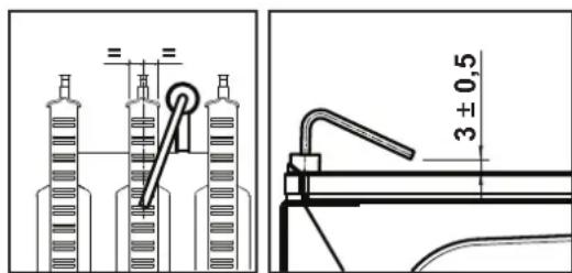
fig. 20 - Electrode positioning
The gas and water systems must be tight.
- The pressure of the water in the system when cold must be approx. 1 bar; otherwise, bring it to that value.
- The circulating pump must not be blocked.
The expansion tank must be filled.
- The gas flow and pressure must match that given in the respective tables.
4.4 Troubleshooting
Diagnostics
The boiler has an advanced self-diagnosis system. In case of a boiler fault, the display will flash together with the fault symbol (detail 11 - fig. 1) indicating the fault code.
There are faults that cause permanent shutdowns (marked with the letter "A"): to restore operation, press the RESET button (detail 6 - fig. 1) for 1 second or RESET on the optional remote timer control if installed. At this point the display will show "d4" for about 30 seconds or "d5" for about 5 minutes which indicates the waiting time after which the boiler will resume normal operation. If the boiler fails to restart, it is necessary to eliminate the fault.
Other faults cause temporary shutdowns (marked with the letter "F") which are automatically reset as soon as the value returns within the boiler's normal working range.
List of faults
Table. 8
| Code fault | Fault Possible cause Cure | ||
| A01 | No burner ignition | No gas | Check the regular gas flow to the boiler and that the air has been eliminated from the pipes |
| Ignition/detection electrode fault | Check the wiring of the electrode and that it is correctly positioned and free of any deposits | ||
| Faulty gas valve | Check the gas valve and replace it if necessary | ||
| Gas valve wiring disconnected Check the wiring | |||
| Ignition power too low Adjust the ignition power | |||
| A02 | Flame present signal with burner off | Electrode fault Check the ionisation check the wire | |
| Card fault Check the card | |||
| A03 | Overtemperature protection activation | Heating sensor damaged | Check the correct positioning and operation of the heating sensor |
| No water circulation in the system Check the circulating pump | |||
| Air in the system Vent the system | |||
| F04 | Card parameter fault Wrong | card parameter setting | Check the card parameter and modify it if necessary |
| F05 | Card parameter fault Wrong | card parameter setting | Check the card parameter and modify it if necessary |
| Fan fault | Wiring disconnected Check the wiring | ||
| Defective fan Check the fan | |||
| Card fault Check the card | |||
| A06 | No flame after the ignition phase | Low pressure in the gas system | Check the gas pressure |
| Burner minimum pressure setting | Check the pressures | ||
| F07 | Card parameter fault Wrong | card parameter setting | Check the card parameter and modify it if necessary |
| A09 | Gas valve fault | Wiring disconnected Check the wiring | |
| Faulty gas valve | Check the gas valve and replace it if necessary | ||
| F10 | Delivery sensor 1 fault | Sensor damaged | Check the wiring or replace the sensor |
| Wiring shorted | |||
| Wiring disconnected | |||
| F11 | DHW sensor fault | Sensor damaged | Check the wiring or replace the sensor |
| Wiring shorted | |||
| Wiring disconnected | |||
| F14 | Delivery sensor 2 fault | Sensor damaged | Check the wiring or replace the sensor |
| Wiring shorted | |||
| Wiring disconnected | |||
| A16 | Gas valve fault | Wiring disconnected Check the wiring | |
| Faulty gas valve | Check the gas valve and replace it if necessary | ||
| F20 | Combustion control fault | Fan fault | Check the fan and fan wiring |
| Faulty baffle | Check the baffle and replace it if necessary | ||
| Flue not correctly sized or obstructed | Check the flue | ||
| A21 | Poor combustion fault | Fault F20 generated 6 times in the last 10 minutes | See fault F20 |
| A23 | Card parameter fault Wrong | card parameter setting | Check the card parameter and modify it if necessary |
| A24 | Card parameter fault Wrong | card parameter setting | Check the card parameter and modify it if necessary |
| F34 | Supply voltage under 180V. | Electric mains trouble | Check the electrical system |
| F35 | Faulty mains frequency | Electric mains trouble | Check the electrical system |
| Code fault | Fault | Possible cause Cure | |
| F37 | Incorrect system water pressure | Pressure too low | Fill the system |
| Water pressure switch damaged or not connected | Check the sensor | ||
| F39 | External probe fault | Probe damaged or wiring shorted | Check the wiring or replace the sensor |
| Probe disconnected after activat-ing the sliding temperature | Reconnect the external sensor or dis-able the sliding temperature | ||
| A41 | Sensor positioning | Delivery sensor or DHW sensor detached from the pipe | Check the correct positioning and operation of the sensors |
| F42 | Heating sensor fault | Sensor damaged | Replace the sensor |
| F43 | Exchanger protection trips. | No H2O system circulation | Check the circulating pump |
| Air in the system Vent the system | |||
| F50 | Gas valve fault | Modulating Operator wiring dis-connected | Check the wiring |
| Faulty gas valve | Check the gas valve and replace it if necessary | ||
| A51 | Poor combustion fault | Inlet/exhaust flue obstruction | Check the flue |
5. TECHNICAL DATA AND CHARACTERISTICS
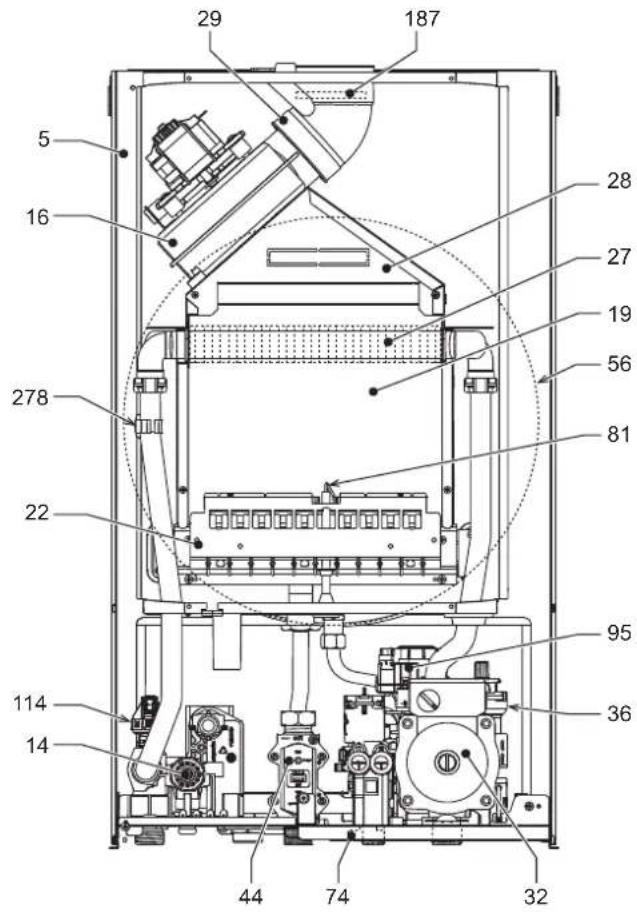
Table. 9-Legend, fig.27, fig.28 and fig.29
5 Sealed chamber
10 System delivery - 0 3/4"
11 System return -0 3/4
14 Safety valve
16 Fan
19 Combustion chamber
22 Burner
27 Copper exchanger for heating and DHW
28 Fume manifold
29 Fume outlet collar
32 Heating circulating pump
36 Automatic air vent
44 Gas valve
56 Expansion vessel
74 System filling faucet
81 Ignition and detection electrode
95 Divertervalve
114 Water pressure switch
187 Fume baffie
209 Hot water tank delivery
210 Hot water tank return
241 Automatic bypass
278 Double sensor (Safety + heating)
5.1 Dimensions and connections
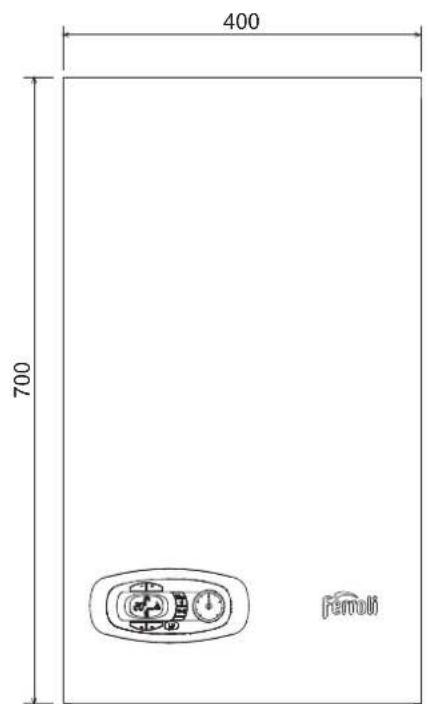
fig. 21-Front view
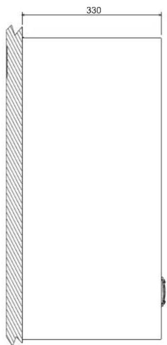
fig. 22. Side view
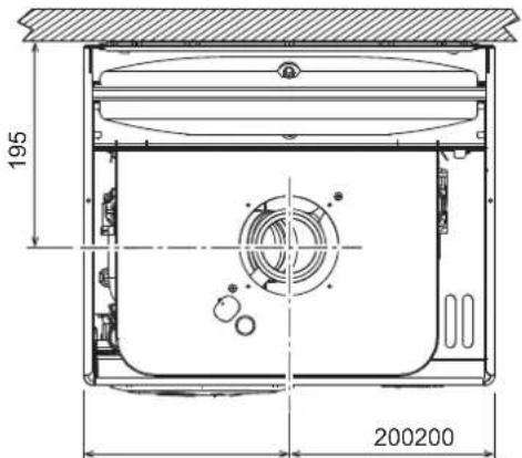
fig. 23-Top view - HF24
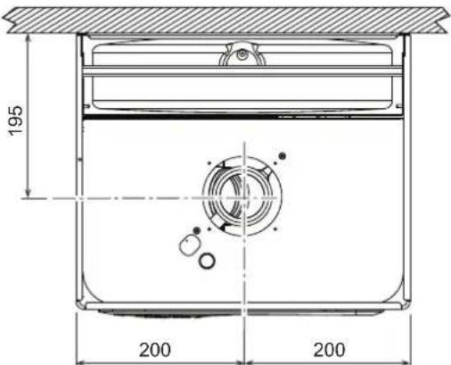
fig. 24-Top view HF32
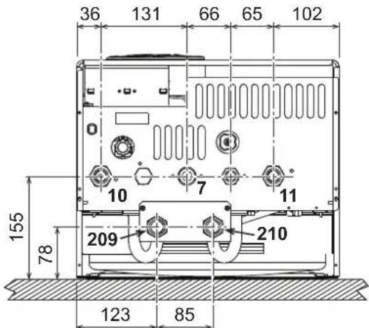
fig. 25-Bottom view - HF24 and HF32
7 Gas inlet - 03/4"
10 System delivery - 0 3/4"
11 System return - 0 3/4
209 Hot water tank delivery - 0 3/4"
210 Hot water tank return - 0 3/4"
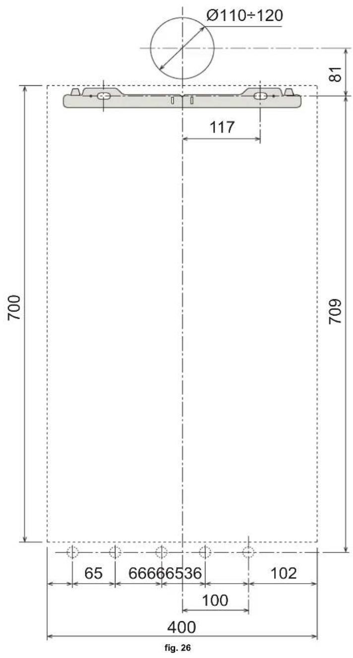
Wall holes
5.2 General view and main components
fig. 27- General view - DIVAtech D HF24
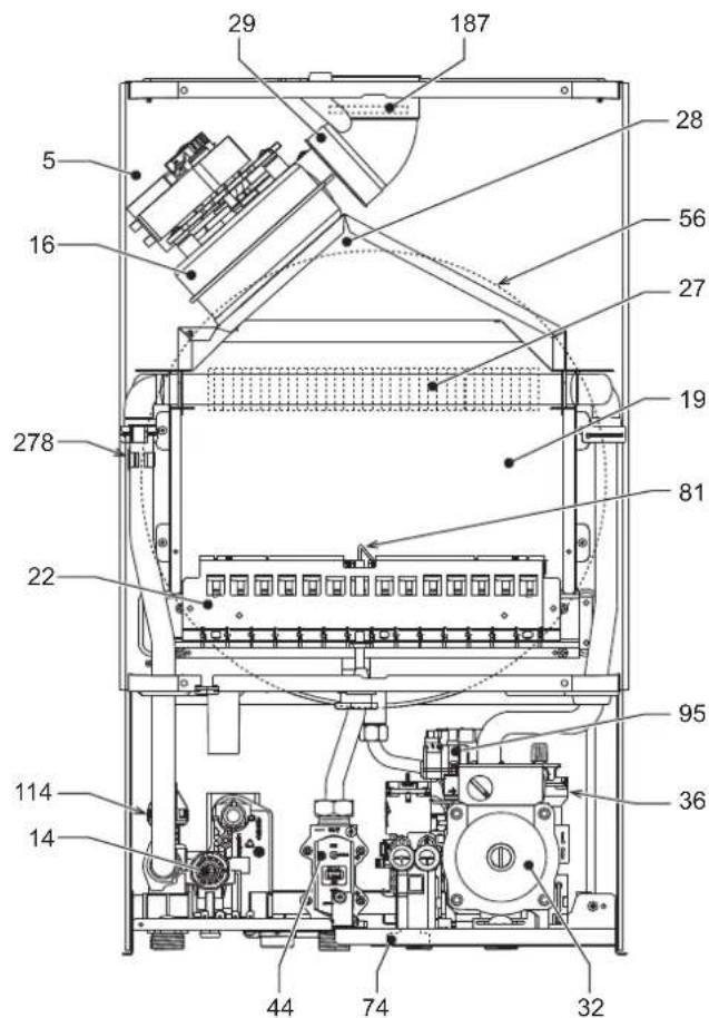
fig. 28- General view - DIVAtech D HF32
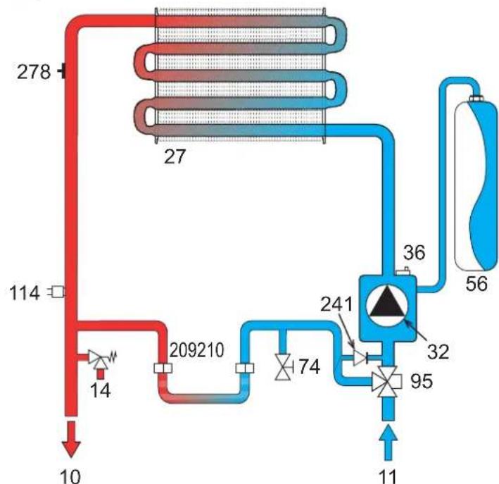
5.3 Hydraulic circuit
fig. 29- Heating circuit
5.4 Technical data table
| Data Unit DIVAtech D HF24 DIVAtech D HF32 | ||||
| Max. heating capacity kW 25.8 34.4 (Q) | ||||
| Min. heating capacity kW 8.3 11.5 (Q) | ||||
| Max. Heat Output in heating kW 24.0 32.0 | (P) | |||
| Min. Heat Output in heating | kW | 7.2 | 9.9 | (P) |
| Efficiency Pmax (80-60°C) | % | 93.0 93.1 | ||
| Efficiency 30% | % | 90.5 91.0 | ||
| NOx emissions class | - | 3 (<150 mg/kWh) | (NOx) | |
| Burner nozzles G20 | no. x 0 | 11 x 1.35 | 15 x 1.35 | |
| Gas supply pressure G20 | mbar | 20.0 20.0 | ||
| Max. gas pressure at burner (G20) | mbar | 12.0 12.0 | ||
| Min. gas pressure at burner (G20) | mbar | 1.5 | 1.5 | |
| Max. gas flow G20 | m³/h | 2.73 3.64 | ||
| Min. gas flow G20 | m³/h | 0.88 1.22 | ||
| Burner nozzles G31 | no. x 0 | 11 x 0.79 | 15 x 0.79 | |
| Gas supply pressure G31 | mbar | 37 | 37 | |
| Max. gas pressure at burner (G31) | mbar | 35.0 35.0 | ||
| Min. gas pressure at burner (G31) | mbar | 5.0 | 5.0 | |
| Max. gas flow G31 | kg/h | 2.00 2.69 | ||
| Min. gas flow G31 | kg/h | 0.65 0.90 | ||
| Max. working pressure in heating | bar | 3 | 3 | (PMS) |
| Min. working pressure in heating | bar | 0.8 | 0.8 | |
| Max. heating temperature | °C | 90 | 90 | (tmax) |
| Heating water content | liters | 1.0 | 1.2 | |
| Heating expansion vessel capacity | liters | 8 | 10 | |
| Heating expansion vessel precharge pressure | bar | 1 | 1 | |
| Protection rating | IP | X5D X5D | ||
| Power supply voltage | V/Hz | 230V/50Hz | ||
| Electrical power input | W | 110 135 | ||
| Empty weight | kg | 32 | 35 | |
| Type of unit | C12-C22-C32-C42-C52-C62-C72-C82-B22 | |||
5.5 Diagrams
Pressure - power diagrams DIVAtech D HF24
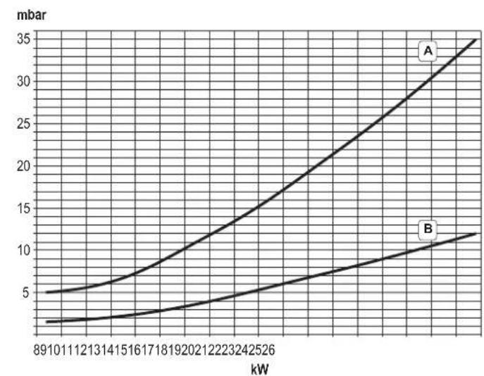
A = LPG - B = NATURAL GAS
Circulating pump head / pressure losses DIVAtech D HF24
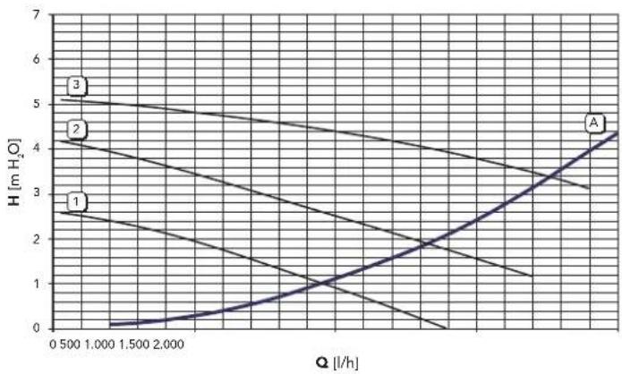
A = Boiler pressure losses - 1, 2 and 3 = Circulating pump speed
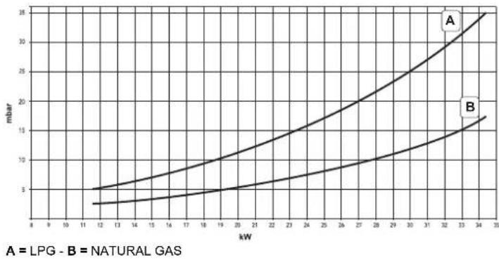
Pressure - power diagrams DIVAtech D HF32
Circulating pump head / pressure losses DIVAtech D HF32

A = Boiler pressure losses - 1, 2 and 3 = Circulating pump speed
5.6 Wiring diagram
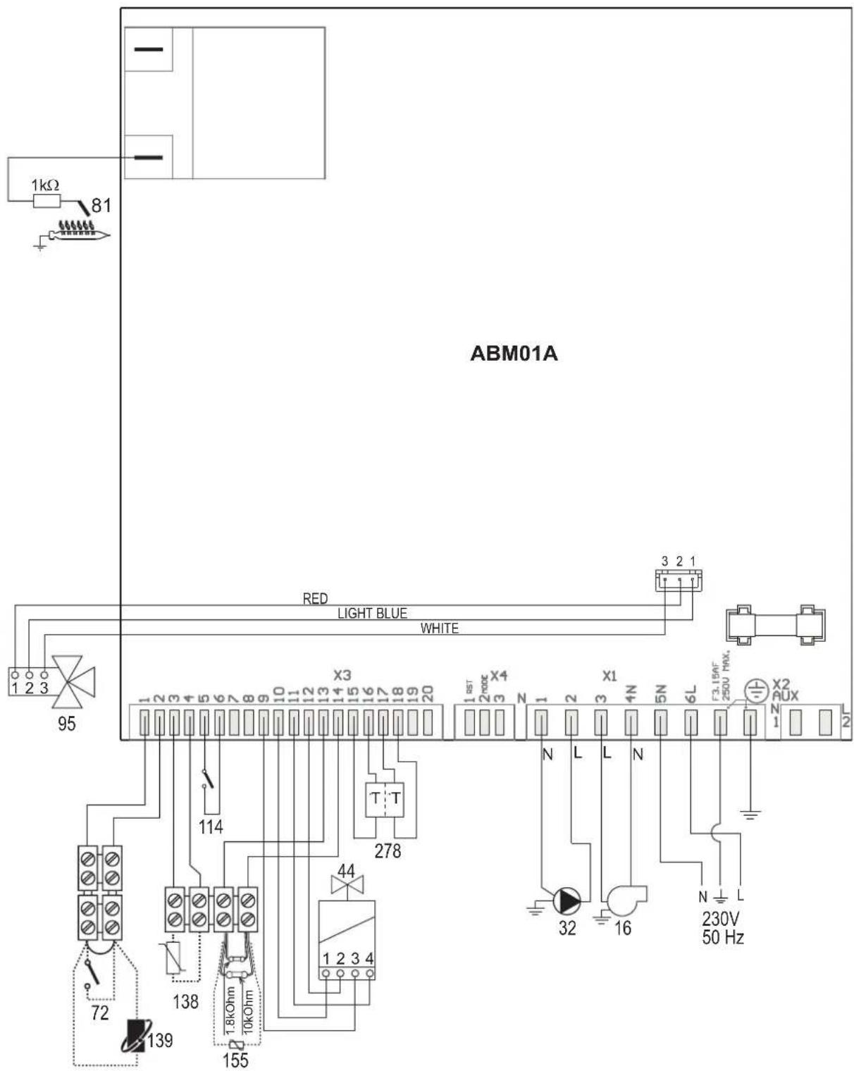
fig. 30-Wiring diagram

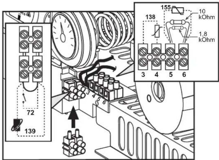
Attention: Remove the jumper on the terminal block before connecting the room thermostat or the remote timer control.
16 Fan
32 Heating circulating pump
44 Gas valve
72 Room thermostat (optional)
81 Ignition/detection electrode
95 Diverter valve
114 Water pressure switch
138 External probe (optional)
139 Remote timer control (optional)
155 Hot water tank probe (optional)
278 Double sensor (Safety + heating)
FR
1. CONSIGNES GENÉRALES
16 Raccordement Service Tool
17 Hydrometre
Selection Eco/Confort
Vidange installation
11 Retour installation - 0 3/4"
95 Bipasse
209 Départ balloon - Ø 3/4"
210 Retour balloon - 0 3/4"
3.4 Raccordement gaz
yCTaHOBka O6OpyIOBaHnI DOnKHa IpnO3BOuNTbCBA COOTBETCTBnC DeNCTBYOuIMM 3aKOHOJaTeNbCTBOM, a N3HaUNBaIOUeNCn DeTaN DOnKHbI 6bITc CBOeBpeMeHHo3aMeHEHbl.
PeeHnEo npeKpaueHnn EKnPyataaun, cnnaHnn Nyttnnaaun npHnMaet BlaJeene uXcOJaN 3aKaTneckoro coctoHHnOBOpDyobAHnN 3atpat Ha peMOHT.
Cpok cnjxkb-10 neT.
3aBODka Ta6nUka HaxoDHTcHa 3aDHe CTOPOHe KOtna.
Manufacturer / PpokoeDmtns: FERROLIS.p.A
Manufacturer address: 37047 San Bonifacio (VR)- Italy
Aapec ppoW3BDoNTenlva Ritonda 78/A
Model/Modenb: DIVATECH D HF24 Code /Ko: 0DAO4ZYA
KOTEN OTONITeNbIra3OBbl KaT.II2H3B/P 2H-G2020Mbap;RU
MAKC MNH
Qnw (Hi) 25.8 - 8.3 kBt PMS 3aP MPW 6ap Qn (Hi) 25.8 - 8.3 kBt tmax 90 °C D
Pn 80°-60° 24.0 -7.2 KBr H2O J
Pn 50°-30° - KBr Knacc NOx 3 (<150mg/kWh)
230B / 50F 110W/BT IPX4D
CdehaHO BVItaHIN
Serial number CepinnbHn Hmep: 1830670021 Bar code EAN13: 8028693868143
Production date: See the manual Дага пожимбовсва:Смогпн Иструкшю
EAC DaHbN npvBopDOnJxHcYCTAHNBtBcB CooTBeCTBmCdEe CTyUcH NTHCtPHKUN No MONTAKH yPabOToT BNOKo B NOme UeHN C DcctATHOH BENTPRAUHN. V3yHTe HnTPOKUN, npe Xde Yem YCTAHABHBa TnpoOp N BBOiTp Eero B KcNtYatauHoc HApUeHHe TpeBcBAH NTHCtPHKUN No MONTAKH. Tex-EXCKTOO 06CbTNKBAHNI NpAABIN CkNtYATAUHN pNpOBoA MOKET NPVBECTM K ONACHOTN BOHMHOBENH NOKapa, B3pBaB, OPApBENH YIap HbM F30M, NpOApEHHN 3AnkTePNUeCKM ToKOM N TepMHNECKKO BO3DNECTM
Qnw (Hi) Maxc. Tepnoponpo3BODHTeJIbHOCTb CNTeMbI IBC (Hi)
Qn (Hi) MaKc. TENJIOpon3BOIDTeJIbHOCTb CNTeMbI OTONJIeHnA (Hi)
Pn 80-60°C MaKc.TenIOnpOAn3BOniTeNbHocTb CnCTeMbI OToJIeHnA (80/60°C)
Pn 50-30°C MaKc. TENnonpon3BODInTeBHOCTb CNTeMbI OToJIeHnA (50/30°C)
PMS MaKc. pa6ouee daBneHnE B CnCTeMe OTONHeHn
tmax MaKc. TempepaTpya B CnCTeMe OTONHeHn
H2O 06bEM BOIDB CNTeMe TBC
NOx Knaacc no BbIbpcam NOx
PMW MaKc. pa6oee daBne B cnCTeMe TBC D PaXoJ TBC npi t 30°C
pnc.1-Panenbynpablenna
YcnoBhie 06o3HaeyHn Ha naHn ynpaBHeHn pnc.1
1 Khonka yMeHbueHn 3aDaBaEMoTEmpeAtpybB CnCTeMe TBC
2 Khonika yBeHnueHn 3aDaaBEmoTempeAtpyb B CnCTeme TBC
3 KhoNka yMeHbSeHHa 3aDaaeMoT TempepaTybpB CnCTEme OToNNHeHH
4 KhoNka yBeHnHeHn 3aDaBaem TeMnepaTyb B CnCTMe OToJIeHnI
5 Dncnne
6 KhoNka "CbPoc" - BbIbop pexKMa "IeTo"/3nMa" - MeHIO "IpaBaIoUaTeMnepaTypa"
7 KhONka Bb6opa pexKIMa "3KOHOMNHyb""KOMΦoPT" - "BKn/Bkn" KOTJNA 8 CmBOn ΓBC
9 CmboJ pa6oTb arperata B pexnme TBC
10 Hnkaaia "Netn pekm
11 HnkaMHHOROyHKUHOHaHbHorpeKIMa
12 CnMBOJpeXIMa"Eco"(3KOHOMHbH)
13 INdkaunpa60bI arperaTaBpeKmE oToNneHn
14 CnMBON OTONJIeHn
15 INHnkaa 3aKKeHHo rOpEnu N TeKyuee MouHocn (Mraet npn c6ox co cropaHem)
16 POnKIOUHeHnE K CpeCTBaM TexHnueckoro 06CnykBAHn
17 Ⅱnpometp
HdkauBaBpempa60tbKOTna
Pexm OTONJIeHn
O NOCTYPNENHIM KOMAHdIbHa BKNIOUOHENHE OTONNNEHIN (OT KOHMATHORO TepMOCTATA HIN OTyNbTa DcTatemepo) npedynpexkdaet mIRAHne INHdkatopena Tennoro Bo3dyxa Ha CDNBOBON 8aapen HuaCnnee.
Ha dncnnee (no3.11 - pnc.1) BbCBeuBaTcTeKyua TEmpeaTpa YoBbl, noDaaEMoB CNTeMy OTOnHeHnA a BO BpMa OxNdaHnOToTneHn - CmBOJ"d2".
PexnTopayeroBDOCh6xHn
O nocTynnEHHn KOMaHbHa BkIIOHcHHe CnCTeMbI ,TeHepnpyEmo np 3a6ope ropeH BoD, npdynpExkaet MrrAHe COOTBETCTByUcero HnDnKATop aod CMBOON kpaHa Ha dnCnIee.
Ha dncnnee (no3.11 - pnc. 1) BbCBeHbAeTc BbXoHna TeMnepaTypa BObl B KOHType FBC, a BO BPem OxNdaHMy BbDau H BoDy FBC-CmMBon "d1".
PexnM Comfort
O OCTyynHn HOMaBHy Na HepeKNoeHne B pexHM (BOcctaHOBNHe NByTpHnei TeMnePAtpyo KOTNa) npdynpExdaet MiraHne NnDkaTopo, paonOnKeHHoro ndo kapanoh. Ha dinCnee (no3. 1 - PNC. 1) BbcBueVbAeTa C TEmnpaTypa BoDy b Kotne.
HencnpaBHOctb
Bcnyae HEnncpabHoctn (cm. cap. 4.4)Ha dncnnee OTObpaKaeTcKoH HEnncpabHoctn (no3.11-pnc.1),a BO Bpem npedeoxpanHTenbHorO OxNdaHmra-HadnnCn "d3", "d4" n "d5".
2.3 Bknoyehne H BBknyoeyHne
IopKnKoyehne K cetn 3JekTpOnTuHaH
B TeueHHe 5 cekyHn Ha nucnIee 6ydt BbICBeYBaTcBepCn nporpaMMHOro o6ecneHn, yCTaHOBNEHHORO B 3NeKTPOHOM 6nOKe.
OTKpoTe ra3OBbI BeHTnIb, yCTaHOBNeHHbI nepeKD KOTnOM.
TenebpKOTENTOB KABTOMaTHueCKOMY BKNUChEHNIO npn kaxdO m3abope ropreH BOdy nnp NoctynIeHN CINHaNA HbKnOHeNE CnCTembl OTONNEHn (OT KOMHATHORTO TepMOCTATA NmY cTjPOTNBA DY C TaIImePM).
BbIKIOeHHe N BkIOeHHe KOtNa
HaKMMTe Ha KONkY BKn./BbKn. (no3.7 - pnc.1) Ha 5 cekyHd.

pnc.2-BbIKnOueHne KOtna
Korda KOTEN BbIKIOHEn Ha 3NEKTPoHHyIO nIaTy npOONKaET NOabatbcra 3NEKTPuueCKOE NITAHne. PnI 3OTM He npOxCODHT HArpeBa BObl dIra CNCTEM OTONJIeHN I FBC. OctaTcA kTINBHOIpOTNBOO6NeEHeNTeNBHa CnCTema. Dn NOBTOPHorO BKIOHEnH KOTNa CHOBA HAKMNTEKnABmSy BKn./BbKn. (no3.7 pnc.1) Ha 5 cekyHn.
pnc.3
3Tm06eeneaeTcERHeMeHneHHaRTOBtOBHcTbKOTnKa6OteKaKdIbpa3npn NotpehnnrOprryBoDbyHn npn 3AnpoCe HoTOnOpHe (noDaBaEMOM KOMHaTHbIM TepMOCTATOM NHy UcTPOINCTOBM INCTAHUONHORO YnpBaJIeHN C TaHMePOM).

Pn OTKIOHcHm KOTnO TcCTeMb3IIEKTPoNtAHnHnUINrA30OBMAMCITPAHNPOTBNO6NEHdHTbHARcCTeMa HpeBaOaET.BOpBMeIINTbHOrHOHECNOPb3OBAHnKOTnB3IMNHnepNoD,BO n36EkaHHeyuepe6aOT BO3MOXHOrO 3amep3AHnPEKOMeHyTeCRnTB BcIO BODy n3KOTnKAk IN3 KOHTpyo OTONHnR,TAHnKOTpyaBC;UNnJe CInTBToNtBOBoYnKOHTypa IBCuO6ABNTb AHnΦpnnB CHTeMy OTONHnBooBTBeCTBmC yKa3AahnMM,PIpBeDEhHBMM B.SeZ.3.3.
2.4 PerynuPoBKn
IpeeknoueHne pexmOB "Jeto"/"3ma"
Haxmte KhoNky "Iero""3Ma" (no3.6 - pnc.1) Ha 2 cekyHdbi.
Ha dncnnee BbcBntncnBON "Neto" (no3. 10 - pnc. 1): Pnp 3om koteen 6ydet BBpabaaTbBaTb TOnbKO BOY DnA TBC. OctaeTcAaTHBHO CNTeMa aHTn3aMep3aHNA.
ДЯ ВБКИСЕНЯ рекIMа "ПeTo" BHOБь HAXMITE KONKY "ПeTo"/"3UMa"(no3.6 - pnc.1)Ha 2 cekyHdbI
PerynnpobKa TemnepaTpybI BoDbI B CnCTeMe OTOnnneHn
Ncnonb3yIe KhoNNK CnCTeMb OTONNEHIN (no3. 3 n 4 - pnc. 1), TTO6bl NmMeHTb TEMnpatypy B mAnao3O MeJdy MmH. 30^ n MaKc. 80^ TEm He MeHee, He pekOMehyETc kcnnyATpOBaB KOtEN npT MnEtnepatypax Hmke 45^
PNC.4
Perynpobka tempepatbI B cncteMe ropaero Boocha6xhenra (TBC)
INONB3yIe KHOHN CNTEMBI FBC (no3.1 n 2 - pnc. 1) DnI INMHeHNI TEMNepaTpyIbOT MHNMIANbHON 40^ DO MAKNCMIANbHON 55^
PNC.5
Perynpobka TemepaTyb BO3dyxa B NOMeueHn (c nomooho onhoHHoro Tepmoctata TemepaTyb B nomeeHn)
3aDaIe N cmoIbIO TepMOCTATA TEPNepATpyB O3OyXa B NOmeuHn HxHyHO TEMNPepATpy BHTPN NOMEUHNE. PInOTCYTCTBN TEPMOCTATA TEPNepATpyB O3OyXa B NOMEUHNE KOTEN 06cEneuBaET NODPepXAHBe B CNTeME OTONNEH NADHNO TEMNepATpy BOIy.
PerynpoBkA TemnepaTybI BO3dyxa B NOMeueHNN (c nOMOuH OOnHOHHoro yCTPOHCTBa Dy c TaHMePOM)
3aadaTe c nOmoIbIO yCTPOIHCTBA Dc TaHMePOM HxHxyo Temnepatyp BHTPN NOMEeHHN. KOTen 5yETnOdEprXmbTbe TMepaPTpy BoDb I CNTME, Heo6xOdmVyo dno ObceeneHHN B NOMEeHHN 3aAHOH TmEPaPTpy Bo3dyxa. B TOM, YTO KaACAeTc pAOBt bKOTNa C yCTPOINCTBOY Dc TaHMePOM CM. COOTBETCTBHyIOUH INCTHpUyHO HA 3TO yCTPOINCTBO.
Bb6oppeKHMOB ECO/COMFORT
Koten o6opbyoan cneuunho fynkue, o6ecnuehbaioe BbCkoHcKoPoCT noaH BOB b CNTEM TBC MAKcmaNbHb KOMfOPT IINONsOBATEA. KOrfa 3TO yCTPOINCTBO 3aedctboaHO (peXm COMFORT), OHO nOdepKmbaET tempeatypy HaxoJaeucB KOTNE BOB, o6ceNwBaT EAMcBm HEmedeHHeo NOCTPNHEI ROpye BOB npn OTKpbTIN KpHa nYcTpAHRe Heo6xOIMOCb JDaTb 3TOr HEKToPOE BpMa.
JaHHOE yCTPOIECTBO MOKET sbbT OTKIOHNO HONb3OaTeNEM (peXHM ECO), HAKAB KNABIMUe eco/comfort (no. 7 - pnc. 1). Pp npaOBe B peXMME ECO HA DnCnnee BbcBcHbAeTcR COOTBECTBYOHIN CMBOIN (no. 12 - pnc. 1). DnB BKIOHOUHIN peXMMa "KOMΦOPT" CHOBA HAXMITE KHONKY "3KOHOOMHHB"/'KOMΦOPT"(no. 7 - pnc. 1).
Плаваюцая Temперatypepa
PnY cTahOBKe BHeUHero DaTHNkA OIouN ApeyINPOBKa KOTNa OcUyecCTBNReTcB P eKIMMe "nnabaOoien Temnepatypb. B 3OM pekmme TemnpaTpya BoDy, noNDaaeMoB N CHTeMy OTONNEHry, perynHypeTcB 3ABNCMOCTN O BHeuHnx KNMIATMueChKx UcNOBN, YTO n03BOJrE ObecneMHb4 kpyrNOrOduHnbMakCMMaHbHy MOKpOPT N 3KOHOmIO 3hePrn. TaK, npn NObIbWeHH BHeHNe TEMepatpyb IONHKAeTCER TMepatpya NODaH N DOby B CHTeMy OTONNEHc ORNACHO HekOTOPOn OPeDEeHNKOMNEHCAuOHN KpBOB.
COrnACHO perynipoBkAM no nnaBaoUeien Tempepatye, Tempepatya, 3aHaHnA KHONKAMM CNTCTMEbl OTOnENHeN (no3.3 -PNC.1) CTAOHNrACMaHbHOI TEMpeATPONoAH B CNTCTMy.PekOMEnyTeTc yctahAbINBaBt ee MaKcMaHbHyo BeINHHY, YTO6bI No3BOINbT CNTCTMeBbIOINHb TYPERNOPOBBO BCEM NOE3HOMpAOOHEmDIA3OHe.
PerynnpOBKoTJDAOONHbblONNHTBCaBnHcMUPPOABHHBMN CNEUANCTAMNNpN erO yctahOBke.BdAbeHneMeH NOB3OBATEb MOKeT cAm N3MeHNTb IN Dn oeceneHnmaKcMaMbHorO kOMΦoTa.
KOMnEHaCauHnHnKpBnA n CmEeHHe KpNbBix
Hakmtte Ha KhoNky c6poca (no3.6-pnc.1) Ha 5 CkyHd OTKpbBaetc DaOCTyn K MeH0 «Pnabaoua TEmnpaTypa» HOTobpaXaTcra MHaOuaH aHnMcb «CU»
IcnoIb3yIe KhoNk CnCTEmbI CBC (no.1 - pnc. 1) Bb6peIte HkyHny XapakTePntKyOT 1 do 10 (pnc.6) Pnp yctAHOBKe KPNBOH Na O peKIM "nnabaiouen TemnepeTpyb" OTKnIOHaetc.
Haxmite Ha KHONK CNTEMbI OTONNEHIN (no3. 3 - pnc. 1) ocyuectBnRETCOdTyN KnapannelbHomy nepeMeHHEN KpBbIX, npn 30m HA dncnnee MMaET cMMBOIN "OF" Ncnonb3yTe KHONK CNTEMbI TBC (no3. 1 - pnc. 1) dny napannenbHoro n3MeHENK KpBbIX B COOTBeTbMn C xapakTePACTHKOn (pnc. 7)
PnnoBtropHom HaxaHn Ha KhoNky c6poca (no3.6 - pnc.1) B TeeyHe 5 ceKyHd OcyuueCTBnEeTcBbXoN4 mHe "TnaBaHOuaa TEmnepatypa
EcH NEMnepatpya B NOMeHHN OKa3bBaTeCn HIXKe JekaemOy, peKoMeHyTeCn Bbl6pTaB xapKaTepcNkO 60one BbICOKOro nopRJaN HAo6OpOT DeIeCTByte, YEbnHnBaN IIN yMehlbua HA Ody EHNiHcynpoRKnBOu OueHnBa, KaKMn Opa3OM 3TO CKaXeTcN Ha BEHNHe HEMnpatpyb B NOMeHHN.
pnc.6-KomneHcauNoHHbEx xapakTepeNCTnK
pnc.7- Pnpmepe npaJIeJIbHOrO CMeueHHKOMNeHcaUHOHBIX XapaKTePnCTNK
PerynpobAHne C ndCTAHNOHHO npbTa ynpabHeHn c TaMepor

B cnhye noqIOHHeN K KOtny npbTa DY C taMePOM (Onnna) BblweonncAHhpepyInpOBKn DOJIKNHb BblNOHHTBCa B COOTBETCTBNC T a6bnu 1.
Ta6nua.1
| PerylnoPobKA tempepatryb bOBo b CnCTeMe otONHeHIM | PerylnoPobKMy KOJIHO OCUJIECTBILT B KAY PeR3 MEHIO PUYIbTA Dc TaimePOM, TAK c N pAnenH yPNAIeHIN KOTNa. |
| PerylnoPobKA tempepatryb b CnCTeMe ropeyero BoDOnchabJHENa (TBC) | PerylnoPobKMy KOJIHO OCUJIECTBILT B KAY PeR3 MEHIO PUYIbTA Dc TaimePOM, TAK c N pAnenH yPNAIeHIN KOTNa. |
| IpeKeHIOUHHePE peKHMOB "JIeTo"?"3HMA" | PeKHM "JIeTo" O6BaJAdE prNPOApTeTOM HAD KOMAHNpH B KIIIOHOUHHePE OTOJIeHIN, KOTOpAR MOKET NOCTYINHb OT PUYIbTA Dc TaimePOM. |
| Bb60ppeKHMOB "3KOHOMUHbI"/ "KOMΦOPT" | Πρ οIaKIOHEnHpeKHMBA TBC c PUYIbTA Dc KOTEN yc7aHaBbIABaETCB B peKHM "3KOHOMHbH" (ECO). B 3Txk yc7b8x KCHONK "3KOHOMHbH""/"KOMΦopt" (no3.7 - pnc.1) Ha pAnenH yPNAIeHIN KOTNa 3abQKIPOBaH. |
| Πρ οIaKIOHEnHpeKHMBA TBC c PUYIbTA Dc TaimePOM KOTEN yc7aHaBbIABaETCB B peKHM "KOMΦopt". B 3Txk yCpONBax c NOMOULIO HcKOMHbH" "/"KOMΦopt" (no3.7 - pnc.1) Ha pAnenH yPNAIeHIN KOTNa MOKHO B6b4b TpIbBb IaXb dByx peKHMOB. | |
| ΠnaBaIoUaTe Tempepatypa | Kak pynLT Dc TaimePOM, TAK έπεKTPOHbB 6bKn KOTNa ocUeCTbIaHTOYPNAIeHIne KOTNOM B peKHMNE "ΠnaBaIoUeH tempepatyba": IN DBx YCTPOJCTB nPrPOPTET KIMEBT 3πεKTPOHbB 6bKn KOTNa. |
Perynpobka daBneHn BOdbicnteMe
DabHeHn Hana npn 3anOnHeHH XoNoDHoro KOHTpya, CHTbBaemoe Inpometpom KOTna (no3.2-pnc.8),doNkHO COCTaBnTbp npiBnHnHTbelho 1,06ap.Ecnn DabHeHne B CNTeMe ynapET Hnke MmHmAbHo NDyCTmBix 3HaueHnK, KOTen OCTaHOBNTcA Ha DnCnnee BbICBeNTcH HeNCpABHOCTb F37.BtIHTne pyky 3anOnHeHH (no3.1 - pnc.8) nOBepHNTE epePHTu cAOBOH CTpenK HA HauhBHe 3HaueHne, P0 OKOHaHH Onepaun BCerda ybipaiTe pyky Ha MeCTO.
Pocne BocCTaHOBHeHnBaIe HnBHeHn B CnCTeMe KOTeN 3anyckaet UKN CTpaBnBaHn BO3dyxa, KOtOpb nnTcra 300 cekynd N o6o3Haayetra Ha dncPiee Hadnncbio Fh.
Bo 366kHHe 6nKOpBCKoTnPAeKOMEHyETcNepNOuCheKn npOBepaTb no MaHometpy DaBnEeBxONo DHOCTMe. PInOnyckAHmDaBnEHHKe0,86ap peKOMEHyETcBOCCTAHOHbTe erOto Tpe6yMoro.
pnc.8-Pyka 3anonHeHH CnCTembl
OnopoxHeHne CnCTembl
CtonopHra raiKa CnBHO rKaHa HaxoHTcR NO npedoxpaHrTeIbHbIM KnaHOM, paONOKeHHbIM BHyTpN KOTNa.
Дя ONOPOXHEHNA CHCTeMbl NOBEPHHTe KOJIbueByo raKy (no3.1 - pnc.9) npOTMB cacoB0 CTpeKIn, YTO6bl OTkpbl KpaH. He INcNoIb3yIte INHCTpymEThn I neiCTByIte TOJIbko PYAKMn.
PnCnBE BoBn H3 KOTnI npedapntelbHO 3aKpOte 3anOpHbI KnaHaBmckdy CnCTeMOH KOITNOM NepED TEM, KAK NOBOPaHbATb CTONOPHyo raiky.
PNC.9- IIOxpaHHTeJIbHbI KnanaH CO CINHBIM KpaHOM
3. MOHTAK
3.1 YkaaHnO o6uero xapakTepa
YCTAHOBKA H HACTPOIKA TOPEIKI DOKHKHA OCUJECTBILTBCR TOJIKBO CNEUANH3NPOBAHbIM NEPCOHOJAM, IMEHOOMN NPOBEEHHYKO KBAMNKAUHO, PPN CO5IOJEHNIPNBEEHbX B HACTOJEM TEXHHCKOM PYKOBODCTBE YKA3AHIN, PEPNDCAHNI DECTBYOUIEFO 3AKOHODATEBCTBA, NOJOKHEN MECTBHX HOPM INPABNI, IN COOTBETCTBN C PNIHHTbIM TEXHHCEKNM TPEBOAHNRMI.
3.2 MecTo yctaHObKn

Kamepa cropahn arperata repMeTHHn 100nipOBa OH OKpykaohcpeDIs, no3Omy OH moKet yctAHABNBATCBN BIObOM NOMEeHN, 3a NCKHNOHEHM rapakEn ABTOPEMOHTbX Mactepcknx.TEm HE MeHee NOMeHneB, B KOTOPOM yCTAHABNAETC KOTEN, DOnkHO IMeTB DOCTATOHYBOBHTNIAUHO nPnpeDToBPAUEHN OANCbHcN cyTuayn B Cnyae yTeek r3a, daXe eCN ONH He3NaHTenbHb. B npOtBNHom Cnyae MOKet BO3HHKHyb ONAChOT bUyEweHN nOpTaBHeN, N6oB3bIbA NOxapa.DaHnHa HopMa 6eONAnchoCTn PnpEDCMOTpeHa DInpKTbBOE EC No2009/142 dnn BcEx arperAOB, patoaOHx Ha ra3e, B TOM CNNE Hn DnT AhsBaEMbIX ARperatOB C 3akBtOIN KAMPOI.
Arperat nprrnoed npr paoBt b uactHNO 3auuueHHo MecTe npn MMHNMaIbHO TemnepeType -5^ Arperat, OCHauneHHB CnuaHbB KOM NnKTEK NTPOTMBZAMEP3AHN, MOKET HNCNBO30BaTcPn MNHIMAbHO TMENepaTy Do -15°C. KOten DOnJeny yctahabnBaTcBcB y kpbIttn, HanpIMeP, noD cKaTOM KpbIhN, BHTPN DaNGKONH INN B zauuueHHO HmUE
BJIb6OM Cnyae, MeTO yCTAOHOBKn DOJIKNHO 6bITb CBO6OaHbIM OT Nbln, OHeONaChbIX npeDMetOB INM MATEpHAnOB HIN eKmX ra3OB.
Koton npedhaaehn HabeuMaHna HA cTeHy n NoCTABnRETC B KOMnBKeT C NOBHeCHM KPOHwTeHOM. KpennneHn K cTe He oJIOHOoBCNEHb TaobnHOct b NpOHOCTb NIOXeHnKOTnA.

Ecnn arperat yctahabHbAeTc cpei Me6eIIN IN6 60KOM KCTHe, CNEyET npedymCmptpetb Cbo6OdHoe npoCTpAHCTBO, Heo6xOdHMOE dna demoHTaKa KOKXya BnIOHNHENOB6hHHx paB0T no TEO6cNYkBAHINHO.
3.3Inpabnueckne nooknoeHna
PpeynpeKdHnA

CInBHOEOTBepCTNE npedoxpAHNTeHBOHOKnanaHaDOnJHo6bIbCoeINHeO CBOPOHKO INCO CNBHOHTpy60B NO36BeXAHHe NnHNHBOBDbHNO B CNYae NOBbUHeHHaDaBnEHn B OTONHTeHOM KOHType.B npoTtBNOM CNYae NtROTOBtENKTONHe Hecet HNKAcO NTbETCBHECHTm 3a 3atONtHHeNHomeeHHn npcpa6abTBaHHn npedoxpAHNTeHBOHO KnanaHa

IpeaBbnoHHeHnem NoKIOHouEHnCneyET npoBepntb,TO annapaT roTO BnApoBcTbMnOHNOM TnONrA3N,OCNEero YBOBnONHTb TuaTeBHyO OHCTKY BCEx Tpy60PBOBOD OTONNTENHO CTmEe.
BbINOHNHTe NOkHNOyEHnK COOTBETCTByOuMm WTyUepaM corlacho ueptexy Ha pnc.25 IN B COOTBETCTBN C CMBOIaMn, IMEIOUIMMCr HA CAMOM arperate.
PnmeuHne: aPerat OCHaueh BHyTpEHHM BaanacbHm KnaHOM B CNTeMe OTONJIeHNA.
XapakTepeNTKBOBdIgNCTeMbIOTONneHn
B cnyuae,ecnn xectKoctb BOby npbeBuaet 25^_r (1^*F = 10 nM CaCO3), nCnOnb3yemar BOa DoNkha 6bItb HndNeKaumm opa3om noDrotOBHeA, TcObbl npedotBaauat bOpa3oBanne HAKIN B KOTNE.
CnCTema 3aunTbI OT 3amep3AHN, XnKnE aHTnΦpn3bl, Do6aKn n HnHn6ntopbl
IcnoIb3oBaHne XnIqKINx AHmPpH3OB, D6abok INHm6ntOpB pa3pe7aetc B cnyae IeO6XoDnMoCTN TOLbKO INKJIHOHTeJIbHO, ECIM INIgOTOBInTeJIb DaET rapAHIO, NOITBePjDaIooHy, 0TO ernpdykUINr OTBeyaET dAHOMY BNDy IcNoIb3oBaHnI H ne pInHINBT BpeDA TENJOO6MeHHNY KOTNA IN DpyTMM KOMNJKETKYOUMM INHm MATEpHaIam, IcNoIb3oBaHnblm B KOHCTpyKUIM KOTNA IN CNTEmbl. 3AnpeuTaTCR IcNoIb3oBaTb XnIqKNe AHTpCmbl, DObABKn INHm6NTOpbl, He npDeH3AueHHHe CNEpHaIbHO DnI PImMeHHNBA TENJBOBIX YctahOBkX IN HecOBMeCTMbIE C MaTEpHaIaMn, IcNOIs3oBaHnblIM B KOHCTpyKUIM KOTNA IN CNTEmbl. OTONHII.
CoeHHeHc6oJepomnIgBC
3NeKtpnoHHa Nnata arerperata npedHaHcHb Taokke dna ynpaaehn HBeuHMM 60nePOM dna npno3oDCTBA BOO tBC. CoepHHeHHY Tpy6 CHTeMbI OTOHNHEM I BC DOnHbI 5bBy BbInOHHeB b COOTBCTBmC co XcEMH pnc.10 BpNtBuHnEe3NeKTPyceMe CoeDHNHEH B COOTBCTBmC 3NeKtpnuecko CXeMoH h pnc. 3O dna 3toN cHn HbeoXoDMIO HCNOb3oBaT KOMnNEKT C KOdO 1KWMA11W.Pncl CnDyoUeM BkIoHHeHH arerata CnCTema ynpaaehn HOno3HaET DaTHK 60nepa H aTOMatuHecM HcTaPAABcTc Hpaoty C Hm, BbIbBaA kTtBaAUHIO DcNpner HycptOB T ynpaehn H, neo6xoDMIIe dna paobTu B pexnme TBC.
pnc.10-Cxema coeHHeHH C BHeuHm 6oHepom
8
BbIXoIΓBC
9
BxoDΓBC
10 POnaA B CnCTEmy - 03/4"
11 Bo3BpaT n3 cncTeMbI - 03/4"
95 PacnpeneJnteHbI KnaHa
209 POnaB6oJnep-03/4"
210 Bo3Bpa n3 6oJnepa - 03/4"
3.4 Ra3OBbIe coeDnHeHn
Ra3 noKnHouaetcK COOTBETCTByoUeMy nATpy6ky (cm. pnc. 25) c co6nHOeHNEM deTCTBYOuHX HOPM, C NcNpNb3OBaHMe JXeCTKO metalAnHeCKO Tpy6bl uIN rIM6kORO WnHaRn HEPKAbEooe CTANn Co CnNoHoi ONNeTKoM Mekdy Ra3onPoBOM n KOTIOM DOnKeH 6blYcTAHOBEn Ra3OBb kpaH. PpOBepTe repMetnHOCtB BceX RA3OBbX CoeDInHeHn.
3.5 3neKtpnueckne coeHHeHHa
PENEYIPEKDEHNA MEPBIPNEIOCTOPOXHOCTN

NEPED BbINONHEHEM IOBbIX ONEPAUIN, IPEYCMATPBBAIOUX CHRTNE KOKYXA,OTKIIOUYAHTE KOTEIN 3JIEKTPMCHECKO CNTN CNOOJIbIOI JIABHO RBIKIOHATEEN.
H N B KOEM CNYA E HE N P N K A C A I T E C B K 3J E K T P U Y E C K N M K O M I O H E H T A M N I N K O T A T M N P N B K I L Q U E H H O N F I A B H O M B B K I L Q U Y A T E N I ON ACHOCTB N P O A X E H H M 3J E K T P U Y E C K N T OKOM P C N K O C M T P A B M N I N C M E P T E L B H O T O M C X O D A!

Annapat DnKhen 6bIb NodKnOHe K aFpEeKTHBHO CNTeMe 3a3eMnHnR, BbIOINHEHBO COOTBETCBMI CJeTBYoUHMn HOpMaMn TEXHNK 6BeONAcHOCTN. 3FpEeKTHBHOCT KOHTyPA 3a3eMnHnM n ERO COOTBETCBNI HOpMAM DnIXHbI 6bIb NPOBepHebl KBANIDPHPOBAHbIM NEPCOHANOM. 13rTOBtEnb He HeCet HNKAKOI OTBCTBEHHOCT3a YUcEp6, Bb3BaHHbI OTCYCTBmE 3a3eMnHnArperataf.
Koten noctabnreTc BblnoHHeHH BHTpyHHe KaBbHoo npoBokn n Chab6Ke OHJINTBbHM shyPOM TpeXNOHOCHOR Tna 5e3 BNKn DnA NOkHHeHH K 3NeKtpnHEcck CTeN. NpOKnIOHeHne K CTeN doXnHO bBbTOcHOBm, pRn 3OTM MeKdy MECTOM NOkHIOHeHH C TeN KOITNOM cDeYET YCTAHOBNT bEyxNIOHOchBpa3MbKATenB c PaccToHMe Mekdy pa3OMKHybIM KKTAKTM He MeHe 3 MM, a TaakpeNoDxaHHTEN C MAkCMMaHbHM HOMHaHbHbM TOKOM 3A. PnO NOkHHeHH K 3NeKtpnHEcck CTeN BaxHo CoNHOdaT noIpaHOCT (NJINHR: KopWHeBB npoBd/ HEITPAJIb: CHHN npoBod/3EMr: XeTTO-3eneHbN npoBOd).

CetBoi uHyp arperata HE NOIDENKUT 3AMEHE CAMM IONb3OBATEEM.B cnyae nobpeckdner CetBoro whypa BbIKIOHHTe arperat n o6patntec bnaero 3aMeHki KBAIINPHUPOBAHHIM cneuaanCTam. B cnlyae 3aMeHbi CETeBOrO shupa NcNOb3yte NKJIOHHTeBHO Kaebn Tnna "HAR H05 VV-F" 3x0,75 MM2 c hapyHKHM dAmETPOM He Boense 8 MM.
TePMoCTaT KOMHaTHOn TeMnepaTypbI (onu)
BHIMAHHE:TEPMOCTATKOMHATHOH TEMNEPATyPbI DOJXEH BbITb YCTPOYCTBOM C KOHTAKTAMM HE NOI HAPRJXEHNEM. PNI IODAue HANPRJXEHN 230 BA HA KJIEMMBI TEPMOCTATA KOMHATHOH TEMNEPATyPbIOBJEET 3A COBOH HENODJIXEAUE EPEMOHTY IOBPEKJDEHNE 3JEKTPOHHOIIIATbl.
PnnoKIOHEN peryIaTOB KOMHaTHOH TemnepaTybC NOBpeMeHHO nporpAMMOynpABAHNEHN Taimepa, He cneyET 3aNtBbATbN xuepe3 pa3MbIAIOUHE KOHTAeTb. B 3aBcHmocCTOn TnA yCTpoiCTBa NITAHHe OdoJeH NoBDoINbCR HAnpMyO OT CTeN INN OOT batapeek.
Octyn K KJIeMMHOI KOPO6Ke
Pn CHrTN N 0bIMBk OTKpbIbAeTc DOCTYN K 3NEKTPNecKO KNEMMHO KOPO6ke. PaONOXeHne KNEMM INx HA3NaueHne NOKa3Ahb TaKHe Ha 3NEKTPNecKO CXeMe B pnc.30.0
pnc.11-DocTyn K KJIeMMHOn Kopo6Ke
3.6bIMOXOaB1
Ppeynpecken
DAnHH annapat OTHOCNTCA K Tnny "C", t.e. K KOTnam C repMeTNUHO KAMepo
CropanH N pInpHdntBHOH TReO. Bo3dyXa360 np BbXOD DbMOBx R a3OB
npNcoeHNHIOCTCOOBtCTBEHNO K CNCTeMaM acnPAuN N bIMOyDAEHN, KOTOpB
DOHNKb YOOBETBOPTB PnPBDEHBM HIXe TpeBOBAHNM. AHHN annapat
ceTPNCHUPOBAH dN pPmHeHNE CO BcEMN KOHfHypaunMM BO3dyXOBOD Cny,
Yka3AHNbHM HA TabNHueKTE XTeHueCKHX DAHNbX. Tem He MeHee, BO3MOXHO, YTO
npImeHHe NEKOTOPBX KOHfHypaun ORpAHNABaETC Nn 3anPeuaTeC MEChTBHM 3AKOHAMn, HOPAMN IN npabnnAMn. PExJde N pncITNaB K MOHTaKy,
BHIMATEbHO O3hAkOMbTEc C COOTBeCTByOuUMN PneINCAHMRN N o6bcNeYbTe NX
CTPORE Co6NDHeNE. Kpome TOrO, Heo6xoDMo Co6NDaBt npabna, KACAOnueCe
pactONOHEHORONOBK BO3dyXOBOD HA CTHe N/NN KpbIe N MHNMAbHBx
pacCToHrN OT OKH, CTEn, DpyrNX BO3dyXOBOD N T.D.
DnaΦparMbI
IЯ obecneueHnra pa60tBJ KOITNa Heo6XoDnmo UCTaONOBHT dnadpArMbJ, npinaaraeMJIe K aRperaty. Y6eHntTeCB, uTo B KOITE HnAOCTN Tpe6yMaER dAonpaRMBA (B Cnyae Heo6XoDnMOCTn EINOLOTBOAHNA) nPOOBepTe npABINbHOCTb eeyCTAHOBKn.
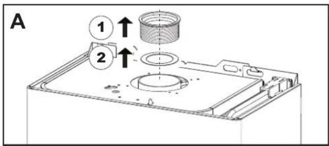
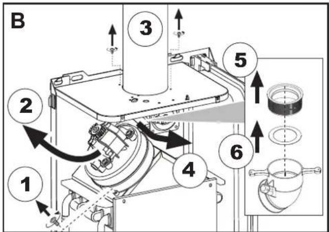
A 3ameHa dnaaeparmbI B He yctahOBneHHOM KOTNE
B 3aMeHa DnafpaMbl B yKe yCTaHOBJeHHOM KOtNe N dbIMOXoA
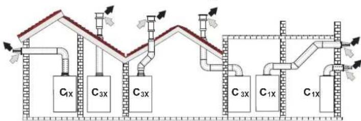
PnoCoeHnHeHne c nmoosbkoKaocnabhBxTpy6
pnc.12-Прмерbl npncoeHHeHc nOmoBbKoakcnalbHbIXtpy6(= Bo3dyx/→=DbIMOBBe ra3bl)
Ta6nua.2-BapnaHTbI nCnonHeHHa
Ta6nua.4-BapnaHTbI nCnoHHeHH
| Tm1 | Haimenohabnne |
| C1X | Горотоньные trубы ддprитока bo3dyaхи и удаленядымовы ra3obчерес委书记.Ологовдддддддддддддддддддддддддддддддддддддддддддддддддддддддддддддддддддддддддддддддддддддддддддддддддддд徳.Ф�говдддддддддддддддддддддддддддддддддддддддддддддддддддддддддддддддддддддддддддддддддддддддддддддддддд徴.Ф�говдддддддддддддддддддддддддддддддддддддддддддддддддддддддддддддддддддддддддддддддддддддддддддддд徴.Ф�ноговддддддддддддддддддддддддддддддддддддддддддддддддддддддддддддддддддддддддддддддддддддддддддддддддд徴Ф�говддддддддддддддддддддддддддддддддддддд徴Ф�ноговддддддддддддддддддддддддддддддддддддддддддддддддд徴Ф�ноговдддддддддддддддддддддддддддддддддддд徴Ф�ноговддддддддддддддддддддддд徴Ф�ноговддддддддддддддддддддд徴Ф�ноговддддддддддддддддд徴Ф�ноговддддддддддддддд徴Ф�ноговддддддддддддд徴Ф�ноговдддддддддддд徴Ф�ноговддддддддддддд徴Ф�ноговдддддддддддд徴Ф�ноговддддддддддд徴Ф�ноговдддддддддд徴Ф�ноговддддддддд徴Ф�ноговдддддддд徴Ф�ноговдддддддд徴Ф�ноговддддддд徴Ф�ноговддддддд徴Ф�ноговдддддд徴Ф�ноговдддддд徴Ф�ноговдддддд徴Ф�ноговдддддд徴Ф�ноговдддддд徴Ф�ноговдддддд徴Ф�ноговддддд徴Ф�ноговддддд徴Ф�ноговддддд徴Ф�ноговддд徴Ф�ноговдд徴Ф�ноговдд徴Ф�ноговдд徴Ф�ноговдд徴Ф�ноговдд徴Ф�ноговдд徴Ф�ноговдд徴Ф�ноговдд徴Ф�ноговдд徴Ф�ноговдд徴Ф�ноговдд徴Ф�ноговД徴Ф�ноговД徴Ф�ноговД徴Ф�ноговД徴Ф�ноговД徴Ф�ноговД徴Ф�ноговД徴Ф�ноговД徴Ф�ноговД徴Ф�ноговД徴Ф�ноговД徴Ф�ноговД徴Ф�ноговД徴Ф果德果德果德果德果德果德果德果德果德果德果德果德果德果德果德果德果德果德果德果德果德果德果德果德果德果德果德果德果德果德果德果德果德果德果德果德果德果德果德果德果德果德果德果德果德果德果德果德果德果德果徴果德果德果德果德果德果德果德果德果德果德果德果德果德果德果德果德果德果德果德果德果德果德果德果德果德果德果德果德果德果德果德果德果德果德果德果德果德果德果德果德果德果德果德果德果德果德果德果德果德果德国果德果德果德果德果德果德果德果德果德果德果德果德果德果德果德果德果德果德果德果德果德果德果德果德果德果德果德果德果德果德果德果德果德果德果德果德果德果德果德果德果德果德果德果德果德果德果德果德果德果 德果德果德果德果德果德果德果德果德果德果德果德果德果德果德果德果德果德果德果德果德果德果德果德果德果德果德果德果德果德果德果德果德果德果德果德果德果德果德果德果德果德果德果德果德果德果德果德果德果德果格果德果德果德果德果德果德果德果德果德果德果德果德果德果德果德果德果德果德果德果德果德果德果德果德果德果德果德果德果德果德果德果德果德果德果德果德果德果德果德果德果德果德果德果德果德果德果德果德果德果得果德果德果德果德果德果德果德果德果德果德果德果德果德果德果德果德果德果德果德果德果德果德果德果德果德果德果德果德果德果德果德果德果德果德果德果德果德果德果德果德果德果德果德果德果德果德果德果德果德果德州果德果德果德果德果德果德果德果德果德果德果德果德果德果德果德果德果德果德果德果德果德果德果德果德果德果德果德果德果德果德果德果德果德果德果德果德果德果德果德果德果德果德果德果德果德果德果德果德果德果康果德果德果德果德果德果德果德果德果德果德果德果德果德果德果德果德果德果德果德果德果德果德果德果德果德果德果德果德果德果德果德果德果德果德果德果德果德果德果德果德果德果德果德果德果德果德果德果德果德果斯果德果德果德果德果德果德果德果德果德果德果德果德果德果德果德果德果德果德果德果德果德果德果德果德果德果德果德果德果德果德果德果德果德果德果德果德果德果德果德果德果德果德果德果德果德果德果德果德果德果瑞果德果德果德果德果德果德果德果德果德果德果德果德果德果德果德果德果德果德果德果德果德果德果德果德果德果德果德果德果德果德果德果德果德果德果德果德果德果德果德果德果德果德果德果德果德果德果德果德果德果神果德果德果德果德果德果德果德果德果德果德果德果德果德果德果德果德果德果德果德果德果德果德果德果德果德果德果德果德果德果德果德果德果德果德果德果德果德果德果德果德果德果德果德果德果德果德果德果德果德果 |
IINIOKNIIOHENI C NOMOUsbpo paednbix Tpy6 yctahOBITE Ha arperat cneDyouyIO CXODHyIO DetanB:
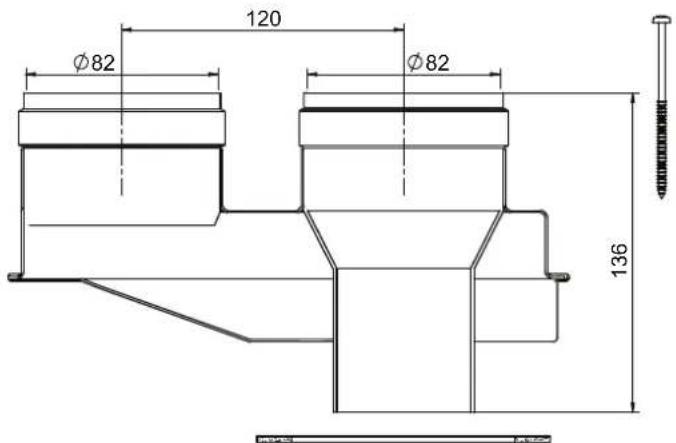
pnc.15-ncxohnnaetanba pa3aebnbix Tpy6, k0d 010031X0
Peped Tm, KAK npctytnab K BbIOnJIeHIO MOHTaKa y6EInTeC, YTO IcNOnb3yeTcR Tpe6yema DnAΦpMa M He npBbUaETcMAKCMaBHO DOYCTMma DnHn a nyTEM npocToR o paceta;
- OkOHnatelbNO onpeIeNtme cXemy npoklaikp 4a3JeIbHbIX Bo3dyXOBoDB, BkIOHOA KcECCyAbHy I bXOJIbHIte TepMInAHbI.
- 06pnttbc8 KaTbIuHa 6 O npTepeJIeNTo NopTeR a3K (3kBnBAHENTHbX Metpax) Ha KAKDOM KOMNHOHTE B 3ABNCIMOCTO NT MecTa ERO YCTAOHBOKN.
- PpOBeBpTe, YTO6bl NOHAR Cymma NToepb 6bIa MEHbSe INI PAHOB MAKCMMaJIbHO DOyNTmOu BEMnHHe, yKa3AHHO B TaBnIa 5.
Ta6nua.5-Dnaaparmblnnpa3dnelbHxTpy6
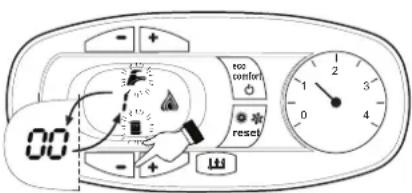
PNC.19 Pexmm TEST (MOUHOCb CnCTeMbOTONJIENH=100%)
Hakmte Ha KHONK CNTEmbOTOnnHeHn (no3.34-PMc.1)IaYBEJIeHHeHn IMyMeHbUeHnMAOIOHOCTM (MMHMAMBHa MOIOHOCTb = 00% -MAKCMaMbHaMOIOHOCTb = 100%
KaHATMEM HA KHONKY CNTEMbI YBC^4 - 6 (no3.1-pnc.1) MOUHOCT bKOTNA HEMEDNEHO HACTPANBAETCA HA MHIMMANbHy (0%). KaHATMEM HA KHONKY CNTEMbI YBC ^ 喜 (no3.2-pnc.1) MOUHOCTb KOTNA HEMEDNEHO HACTPANBAETCA HA MACHIMMANbHy (100%).
B cnyuae aekmbauin pexmMa TEST n 3abopa BObI IBC,doctatoHoro dnaakmbauin pexmMa IBC, koteo octaetcB pexime TEST,HO 3-xoobO Knlanah nepeknuaeTcB pexim IBC.
ДяOTKIOHcHnpeKIMa TEST OJHOBPeMeHHo HaxMITE Ha KONKm OTONJIeHn (no3. 3 n 4 - pnc. 1) B TeueHne 5 ckyHd.
Pekim TEST B IIb60m Cnyuea ABToMaTnueckm OTKHNoHTC Tcepe3 15 MmHT mN no 3abePuhenm 3abopa BoDyI BTC (B cnyuea ecn n BeInMHa 3abopa doctatoOna dIraakmbauin peKIma IBC).
Perynpobka MouchoTn OTonHeHHa
Дяретулковь мошостгу отолелу усаловп ST (m. sez. 4.1). Habима.THONK3дади Tempepatbyb BODI b CNTSEme OTONELHIN (no3.3-puc.1)ДЯ COOTBETCTBEHHORO YeIMUHENI yM yMeHSLHIN MOLCHTIN (MHINMAMHBaR = 00 / MakcIMaHbAra = 100).Пин HAKATN B TEEHNE 5CEkYN NOCE 3TOrO KHOKNIC "C5POC"COxpaHHTCToTbKbTO 3aDAHARMAKCMaHbHaB MOHOCt. BMyDnTE hPekMa TEST (cm. sez. 4.1).
MeHIO KOHmrypaun
DcTyn K MENI KOHmpyaunm oBecnneHMaetcO HIOBpeMeHbM HAKATHM IHNOK BC HA 10 CkyHd. IMeOTc12napaMeTp, o6o3auHHHe b' tAke napaMeTp He MOrY IaMeHTbC Tc yCtPCTaa DnCTAHIOHOHOrO YnpaBHeNc T cTaHEOpM
C NOMOJIbHO HONOK OTONNEHIN MHEETC B03MOXHOCTb IPOCMATPBtB CnCHOK napaMeTPOB B NOPIAKe BO3PACTAHN mYbSbAHN. YTObI OTObPA3NTb IMM3MEHTB 3HAeHHe NapaMeTpa, DOctaTOHO HCNOJI3BOATb KHONI TBC: 3M3MEHHeN COxPAHReTC ABOTMAUcKm.
"tS"-MeHIO npo3paHbIX npaMaTePOB
PpeyCMTOpeHO 21napaMeTPOB,OTMueHHbIX6yKBoON“P”,KOTOpIe MOXHO N3MeHrTB,B TOM uNcNE,C nybTa DnCTAHIOHHO ynpabHeHnC TaimepoM.
C NOMOZbIO KHOJOK OTONJIENHIM MEETcER BO3MOKHOCTb POCCMATPBATb CNICOK NAPAMETPOB B NOPIRKe B03pactAHN Iy6bBAHm. Yo6b OTO6pa3HTb INI INM3MeHb3A2HHeHn NapAMETP, DOCTAOHO NCNOB308b KHOKNI BC; INM3MeHBeCOXPAHETBC AOTMAITHeCKN.
IINBbIXOaN3MeHO "Service" 3NEKTPONHNOIaTbHeo6xmoHMO HaxTa bKHOky"Reset" B TeueHnE 20cKyH NmnoOxdaTb 20MHyT, T06bI pOn30wlo ABOMATHECKOE BkHIOeHnE.
4.2 BbONB 3KcnnnyatauHn
IpepeBknHcHemKOTna
PpOBepeTepemTuHcTbCnCTeMbI NOBDAra3a.
- PnpoeBte npabInbHocTb npdeBapntelbco3aHHoro B paCUnpTeHbOM CooDeA daNHeNo.
3ANOHNHTe CNTeMY BOOIOI NIOHOCTBIO CNyCTMe BO3dyX I3 KOTNA INCCTEMbl OTONBNEH.
UdoCTOBepBeTbE BOTCYCTBENYTEK BOEDIaN3CNTEMbI OTOPTNA BC, KOTNJIaBPAJINHbX COEHNHEYNX.
IpoBepbTe npabHbHOCTb BbINOHNHeHn 3NEKtpNccknx CoeINHeHn I 3OΦeKTHBHOCTb 3aEMJIeHn.
YDOCTOBepbTecb,TO BENHnHa daBHeHHra3a COOTBeTcByIOT Tpe6yEMomy 3HAeHHIO.
PbTe,TOB HENOpCdCTBeHHOH 6N3OCTn OT KOTNa HE HAXOATCR OrheonaHe XIDKOCTN MATEPAHn.

IPN HECO5HIOJEHN BbIeEYKA3AHHbIX NHCTPYKcIM MOKET BO3HnKHyTb ONACHOCTb YdyUeHn IIN OTPABLeHnI NO IPNpNHBE BbIXOa RA3OB INI IbMOB, A TAKKE ONACHOCTb IOXAPA INI B3PbIBA. KPOME TOFO, MOKET BO3HnKHyTb ONACHOCTb NOPAXEHN 3NEKTPuHECKM TOKOM INI 3ATONJIENH NOMEUeHnI.
KoHTpoBbHbIe Opeaun, BbINOJIHReMbIe BO BpEmpa6Obl
Bknouthe annapat.
PpOBepeTepemTe TOnNNBHOKOHTypa N BOONPOBOOB.
- Pnpi pa60taoouem KOTne pnopeBte, HOPmabHIOI PA60taot bot bIMOXOD n B03xynOBOJd IINPNTOKA BO3DyXu and YdaneHINbIMOBXtRa 3030.
- PnpoeBte, npabnilbno nIuKpyepet BoJa MekJy KOTlOM IN CnCTeMOI OTONJIHIN.
YDOCTOBepbTecb, YTO rAOBbI KJIANAH npaBnJbHO oBeCneuBaET MOyNIO MOUHOCIN, KAK B pexmE OTONNEHNA, TAK N B pexmE TBC.
IpoBbTe paboty cncTbMy po3KHa KOTnA. DnA 3TOr HOECKOBKO pa3 BKNHOHTe N BkIOHcOTKeIpyET em peryIINPOBKn KOHMATHORO TepMOCTa HIN C PYNbTa MCTAHUONHOrO ynpaJIbHeNIA.
- YdOCTOBepbTecb no NOKa3AHnM CcETyNkA, yTO paCXoD r3a COOTBcTByET BeHnHe, yKa3aHHoB TabNtue TeXHnEeCKNX daHHbX B cap. 5.
PpOBeBpTe, yTo npn OTCyTcBm CmHrHa Na BkNIOeHne OTOnNEHn, rOpEnKa 3aKnaAeTc npn OTKpbTmN JIOBO KpHa CmCTEmbl BC. YOcTOBpeBpTeCb, yTo BO BpEma pa6oTbI B pEXKIMe OTONNEHn npn OTKpbTIn N KpHa TpOJeH BoDbl OCTaHABINBaETc RnPKyIraIOHOHHb HAcOC CmCTEmbl OTONNEHn n PpOIm3BODNTcB bIp6oTka BObl BC.
- PnpoeBpTe npabHbNbHocTb 3anPorpammmpoBaHHbIX napAmetpoB n, eCNI Heo6xOJIMO, BHeCte Heo6xOJmble N3MeHeHn (KpBraI NOrOo3aBNCMOrO perynipobAHnA, MoUHOctb, Tmemepatya I.T.D.).
4.3 TexHnueckoe 06cnyKuBaHne
PNEyPPEKDEHnI MEpbI PEPDOCTOPOXHOCTN

BCE ONEPALINI NO TEXHNECKOMO BCLYKBAHMO NIN3AMEHE KOTIA DIOJXHBI BINOJIHTBCR CIEUANIMPOBAHHBM INPEPCOHAIOMCNOITBEPXDHENHO KBAJNFOKAUENI.
Peped BbINONHeHEm NIObIx ONEpaunn BHyTpN KOTNa OTKnOHTe 3JIeKTPoHHTaHE n 3aKpOte rA0BbI BEHTNb, yCTAHOBNEHHbI nepeD KOITnom. B npTINBHOM cnyae MoKet BO3HNKHyt b PNC B3pb1Ba, 3JIeKTPuueckoro ydapa, ydyueHn Hn OTpaBneHn.
PepnoDnueckn KOHTpOb
Tc6bI o6ceNeHTb HcnpabHyio pa60Ty arperata C TeueHem BpeMeHH, Heo6xOJIMOp a3 B rOda pnrnlaaTb KBaHmФuNpOBaHHb NepcoHAn Dn CneDyUHX npOBePOK:
- YnpabJHOUHne n npdeoxpAHnteHbHe yCTpoiCTBa (ra3OBm knaHa, pacxOdomepbI, TepMOCTaTb I np.) DOJIKNbI NCpapBO p60TaTb.
KoHTyp OTbOda DbMa doJnKeH 6bTb 6e3yKopn3EHHo 3ΦfKeTHBbIM. (Koten c 3aKpItoi Kamepo: BEHTNIATOp, pene daBneHn np. - 3aKpItaKa mepa doJnKHa 6bTb repMeTuHOn: npoknAkn, npNkMbl nra Ka6BeNe n np.) (Koten c oTKpItoi Kamepo: AHTnHaHeTateIb, termocstat dBaMa n np.)
TpybopobOdbI oronOBkI nIa3abopa Bo3dyxa IOTbOda IbIMa He doJXHb6bITb 3arpoMoxHeHnHEdoJXHb IMETb yTeHek - TOpEnKa IeTNOoBMeHHK DOnJIbHb 6bIb YChtBuMn 6e3 OToJXeHmN. JIIN XOCHTeH IE CNOJIoB3yTe XIMHeMHcE NPOdYbTb INI CTaJIbHbIE QTeKH.
3neKtpoH He donxKeH HMeTb Harapa n DonxKeH npaBnIbHO pacnoJaraTbcra.
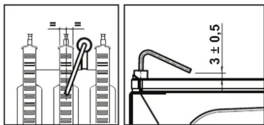
pnc.20-Ponoxhene3JeKtpoDa
Bce ra30bIe n rnpabInueckne coeINHeHn DOnKhbl 6bl TepMeTnHbIMN
-Давелене BOДБИ BXOLOHOM OTONITIELHOM KOHTYPE DOJNKHO COCTABNtB OKO1 6apa;В npOTNBHOM CNYae cNeDyET HAcTPONTb 3TO 3HaHeHne.
LupkyraHHHbHaoc He doJKeH 6bItb 3a6nKpObaHHbIM
PacunpuTeIbHbI 6aDjXKeH 6bIT3aONHeH
Pacxod n daBJIeHHe r3a doNKHb COOTBetCTBOBaTb 3HaueHnM n3 COOTBetCTByOuNX Ta6nU.
4.4 YctpaHeHHe HEmcnpaBHOtei
DnarHOCTNka
Kotien ochuencopeMeHHOINCTeMoIcAmoHnHocHTNk. B cnyae BO3HNKHOBEHINKAOKI-LOHEHnCPABHOCTN B KOTNE CUNPEN HaHuHAE MIRAtb BMECTe CMBBOLOHEHnCPABHOCTN (NO3.11-PNC.1), OTobpaKaK KOd 30T HeMnCPABHOCTN.
MEHOTcH HENCPaBHOCTN, Bb3bIbAOJIne NOCTOHHYIO 6NOKHPOBKY (06o3HaayaeMbte 6yboiA):IIN BO3o6HOBNEHn PABObTIO DCTOATOHO HAKaTB KNaBNIu CYCPOC (no3. 6-pnc.)1 Ha 1 cekHy nIn, pnp HauHNHy, KNaBHIy CbPOC HA npyTe DY c TaMepOM (onu). PpN 3TOM Ha DNcPiee BbCBeNTcR HADmCb "d4" pnpMeHr HO 30 cekHyD N56o" d5" pnpMeHO Ha 5 MMyT, NKa3bIBaB Rbpem OkNDaHn, No IcTeHeHHN KOtOPOro KOten BO3o6HOBINT HopMaIbHYo pa6Oly. Ecnn 3TORo He npOn3oJET, Heo6XoHmo YcTpaHInb HENCPaBHOCTb.
DpyrHe HcnpbHOCTN (O603HauaeMble 6yKBOI F") Bb3iBaIO TBeMeHHyO 6knipOBky,KOTopA CHmAETC ABOMtHeCKn,KAK ToJIbKO bI3BabWn C60n napameTPOB3PaaeTBC HOPMaHbIhe paOoMe npedJe.
IpeuehB HeucnpaBHOtei
Ta6nua.8
5.XAPAKTEPNCUNI TEXHNECKNE DAHHBIE
TaBnua.9-Cncocoko603naeHnn,pcn.27,pnc.28 npnc.29
5 RepmTeHHaKamepa
10 PnDaaB CnCTeMy - U3/4"
11 Bo3Bpar H3 CnCTeMbI - U3/4"
14 PpeoXpaHnteHbHnKnanaH
16 BeHTMIRTOP
19 Kamepa cropania
22 Fopenka
27 MeHn Tennno6MeHHN Dn r ChTeM OToTneHn I TBC
28ДьIMOBOKONNEKTop
29 NaIpyboK DnA OTBODa BIMOBbIX Ra30B
32 LiXpyIaIOHbHb HAcoc CmTeMb OToTnHeH
36 ABToMaTHueckn BO3DyXooTBO
44 Taeobb knanaa
56 PacnntbHbB 6aK
74 BeHTnB JIJI 3aONITHEH NCMTeMbI
81 Pndkraoounm/cnepaunn 3neKtpo
95 PacpepeHntenBbHn Knaan
114 Pene daBneHn 30db
187 Daapma Dm08bx ra30B
209 POnaHaB6oJnep-03/4
210 Bo3BpaT BoDJI 3608nepa-03/4
241 ABToMaTHmHeckmOBbOHOH KtpanaH (BaImac)
278 10BnHnI dAHTN (IpeDgOxHAn-ITHeHn+ I EternepaTpybIbOdAByBcKCTMEOTONENHnI
5.1 PaaMepbI u coeHHeHHa
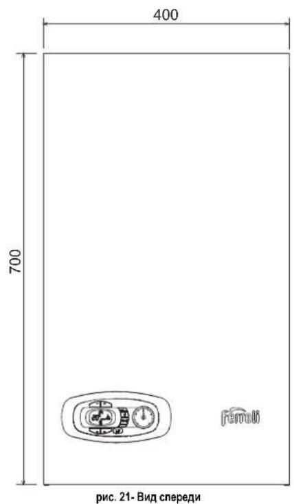
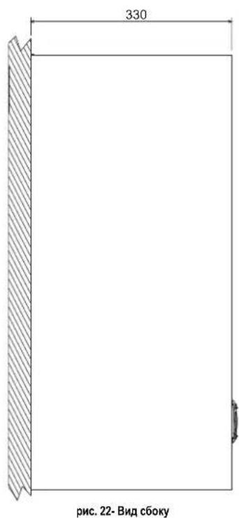
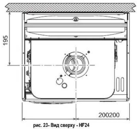
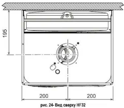
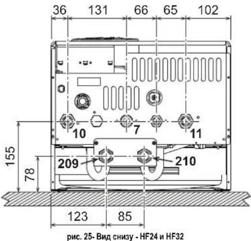
7 10B0ra3a-03/4"
10 NoaB CnTeMy - 3/4"
11 Bo3BpaT n3 cHCTeMbI - 03/4"
209 IOnaay BOnbl BOnnep-
210 Bo3BpaTBoDbIu36oInepa-03/4"
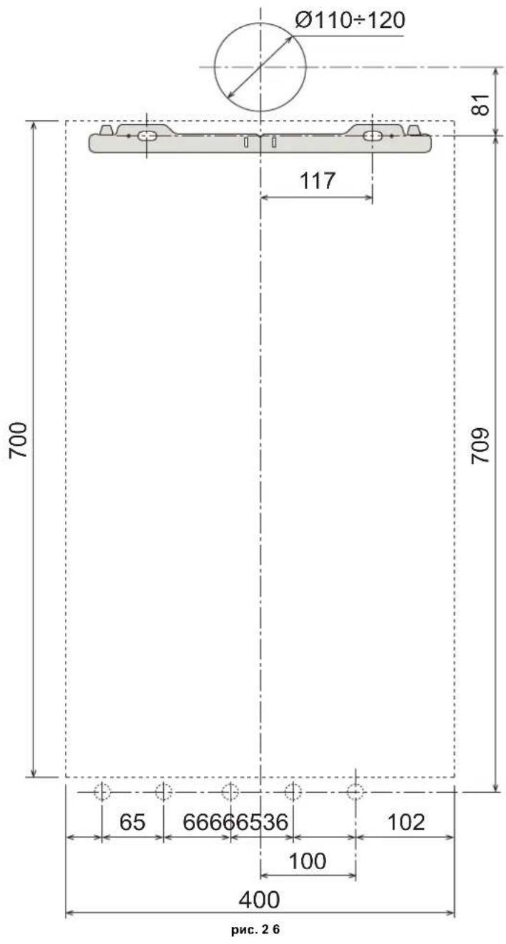
HacteHHbIe OTBepCTMa
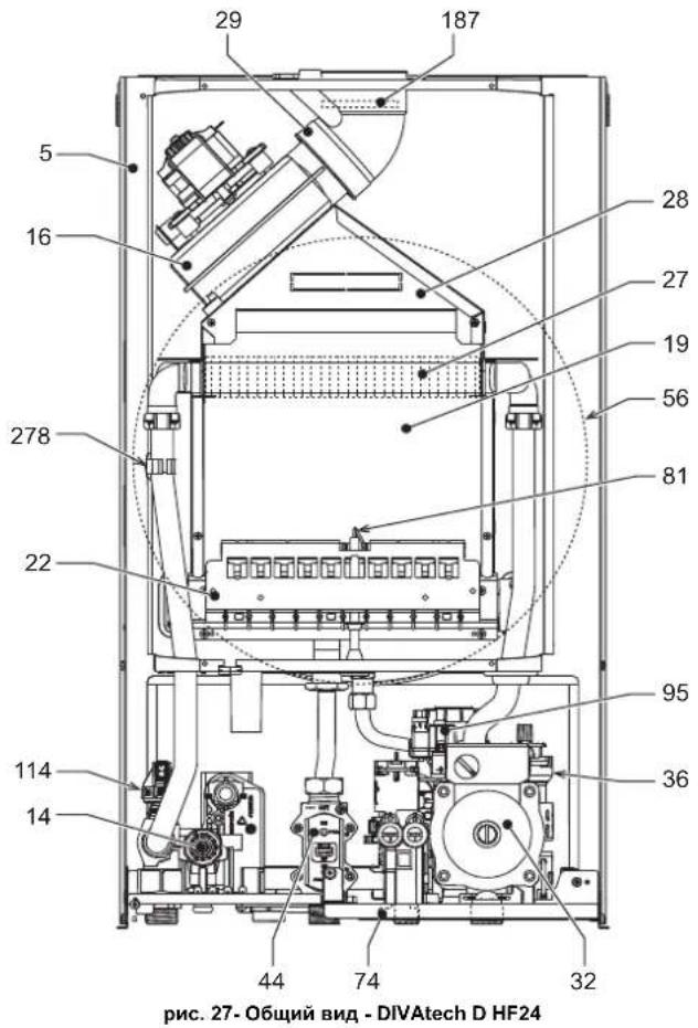
5.2 06HIM BUN N OCHOBHbIe KOMTOHEHTbI
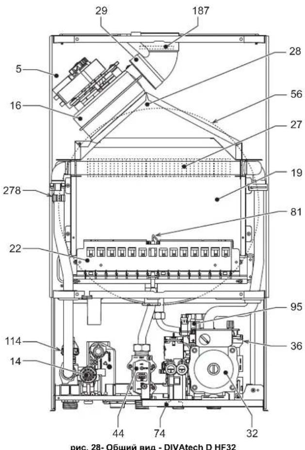
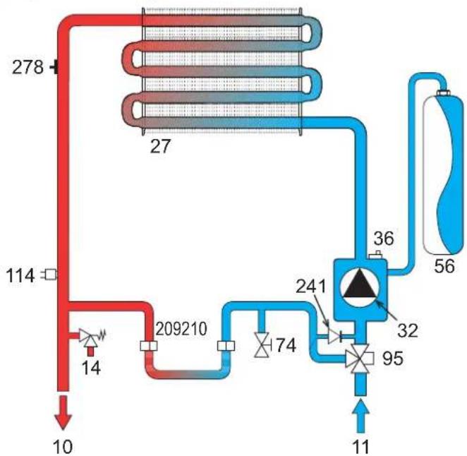
5.3InpabnuecknoKoHTyp
PNC.29-KoHTyp oToTneHn
5.4 Ta6nua texHHuecknx daHHbIX

- DIVAtech D HF24/HF32
- C E
- EAC
- IT
- AVVERTENZE GENERALI
- OPERATING INSTRUCTIONS
- Introduction
- Control panel
- Indication during operation
- Heating
- Domestic hot water (DHW)
- Comfort
- Fault
- Lighting and shutdown
- Connection to the power supply
- Turning the boiler off and on
- Adjustments
- Summer/Winter Swithchover
- Heating temperature adjustment
- DHW temperature adjustment
- Room temperature adjustment (with optional room thermostat)
- Room temperature adjustment (with optional remote timer control)
- ECO/COMFORT selection
- Sliding Temperature
- Adjustments from Remote Timer Control
- System water pressure adjustment
- System draining
- INSTALLATION
- General Instructions
- Place of installation
- Plumbing connections
- Important
- Water system characteristics
- Antifreeze system, antifreeze fluids, additives and inhibitors
- Connection to a storage tank for domestic hot water
- Gas connection
- Electrical connections
- Room thermostat (optional)
- Accessing the electrical terminal block
- Fume ducts
- Baffles
- Connection with coaxial pipes
- SERVICE AND MAINTENANCE
- Adjustments
- Gas conversion
- ALL COMPONENTS DAMAGED DURING CONVERSION OPERATIONS MUST BE REPLACED.
- Activation of Auto-setting function for gas valve calibration
- THIS PROCEDURE MUST ONLY BE CARRIED OUT IN THE FOLLOWING CASES: GAS VALVE REPLACEMENT, CARD REPLACEMENT, CONVERSION FOR GAS CHANGE.
- Gas valve pre-calibration
- Gas valve calibration
- Checking of gas pressure values and adjustment with limited range
- TEST mode activation
- Heating power adjustment
- Configuration Menu
- Notes:
- Service menu
- “tS” - Transparent Parameters Menu
- "In" - Information Menu
- "Hi" - History Menu
- "rE"-History Reset
- Commissioning
- Before lighting the boiler
- IF THE ABOVE INSTRUCTIONS ARE NOT OBSERVED THERE MAY BE RISK OF SUFFOCATION OR POISONING DUE TO GAS OR FUMES ESCAPING; DANGER OF FIRE OR EXPLOSION. ALSO, THERE MAY BE A RISK OF ELECTRIC SHOCK OR FLOODING THE ROOM.
- Checks during operation
- Maintenance
- ALL MAINTENANCE WORK AND REPLACEMENTS MUST BE CARRIED OUT BY SKILLED QUALIFIED PERSONNEL.
- Periodical inspection
- Troubleshooting
- Diagnostics
- List of faults
- TECHNICAL DATA AND CHARACTERISTICS
- Table. 9-Legend, fig.27, fig.28 and fig.29
- Diagrams
- Wiring diagram
- FR
- CONSIGNES GENÉRALES
- Selection Eco/Confort
- Vidange installation
- Raccordement gaz
- YcnoBhie 06o3HaeyHn Ha naHn ynpaBHeHn pnc.1
- HdkauBaBpempa60tbKOTna
- Pexm OTONJIeHn
- PexnTopayeroBDOCh6xHn
- PexnM Comfort
- HencnpaBHOctb
- Bknoyehne H BBknyoeyHne
- IopKnKoyehne K cetn 3JekTpOnTuHaH
- BbIKIOeHHe N BkIOeHHe KOtNa
- PerynuPoBKn
- Perynpobka tempepatbI B cncteMe ropaero Boocha6xhenra (TBC)
- PerynpoBkA TemnepaTybI BO3dyxa B NOMeueHNN (c nOMOuH OOnHOHHoro yCTPOHCTBa Dy c TaHMePOM)
- Bb6oppeKHMOB ECO/COMFORT
- Плаваюцая Temперatypepa
- PerynpobAHne C ndCTAHNOHHO npbTa ynpabHeHn c TaMepor
- Perynpobka daBneHn BOdbicnteMe
- OnopoxHeHne CnCTembl
- MOHTAK
- YkaaHnO o6uero xapakTepa
- MecTo yctaHObKn
- 3.3Inpabnueckne nooknoeHna
- PpeynpeKdHnA
- XapakTepeNTKBOBdIgNCTeMbIOTONneHn
- CnCTema 3aunTbI OT 3amep3AHN, XnKnE aHTnΦpn3bl, Do6aKn n HnHn6ntopbl
- CoeHHeHc6oJepomnIgBC
- Ra3OBbIe coeDnHeHn
- 3neKtpnueckne coeHHeHHa
- PENEYIPEKDEHNA MEPBIPNEIOCTOPOXHOCTN
- TePMoCTaT KOMHaTHOn TeMnepaTypbI (onu)
- Octyn K KJIeMMHOI KOPO6Ke
- 3.6bIMOXOaB1
- Ppeynpecken
- DnaΦparMbI
- Ta6nua.4-BapnaHTbI nCnoHHeHH
- Perynpobka MouchoTn OTonHeHHa
- MeHIO KOHmrypaun
- "tS"-MeHIO npo3paHbIX npaMaTePOB
- BbONB 3KcnnnyatauHn
- IpepeBknHcHemKOTna
- KoHTpoBbHbIe Opeaun, BbINOJIHReMbIe BO BpEmpa6Obl
- TexHnueckoe 06cnyKuBaHne
- PNEyPPEKDEHnI MEpbI PEPDOCTOPOXHOCTN
- PepnoDnueckn KOHTpOb
- YctpaHeHHe HEmcnpaBHOtei
- DnarHOCTNka
- IpeuehB HeucnpaBHOtei
- 5.XAPAKTEPNCUNI TEXHNECKNE DAHHBIE
- TaBnua.9-Cncocoko603naeHnn,pcn.27,pnc.28 npnc.29
- PaaMepbI u coeHHeHHa
Brand : FERROLI
Model : Divatech D
Category : Central heating boiler