
Opera - Central heating boiler FERROLI - Free user manual and instructions
Find the device manual for free Opera FERROLI in PDF.
| Product type | Condensing central heating boiler, pre-mix, low temperature |
| Brand | Ferroli |
| Model | Opera (series 70 to 450 kW) |
| Nominal thermal output | From 64 kW (Opera 70) to 413 kW (Opera 450) |
| Efficiency at 30% load (50/30 °C) | Up to 109.7% |
| Electrical supply | 230 V ~ 50 Hz |
| Maximum electrical consumption | From 105 W (70) to 800 W (450) |
| Dimensions (L × D × H) | Varies by model; e.g. Opera 70: approx. 600 × 800 × 1400 mm (refer to manual) |
| Empty weight | From 230 kg (70) to 550 kg (450) |
| Maximum working pressure | 6 bar |
| Maximum heating setting temperature | 95 °C |
| Gas type | Natural gas (G20) or LPG (G31), adaptable |
| NOx emission class | 6 (< 56 mg/kWh) |
| Protection rating | IPX0D |
| Main functions | Heating, DHW production (with optional tank), timer programming, summer/winter mode, evolutive temperature, antifreeze, self-diagnostics |
| Maintenance and cleaning | Annual maintenance by qualified professional; clean combustion chamber with BIO INF product (or equivalent) |
| Safety | Overtemperature protection, flue gas safety, pressure switch, antifreeze, safety gas valve |
| Spare parts and repairability | Original Ferroli parts; repairs by qualified professional |
| General information | Complete manual (304 pages); available for free download; Ferroli technical support |
Frequently Asked Questions - Opera FERROLI
User questions about Opera FERROLI
0 question about this device. Answer the ones you know or ask your own.
Ask a new question about this device
Download the instructions for your Central heating boiler in PDF format for free! Find your manual Opera - FERROLI and take your electronic device back in hand. On this page are published all the documents necessary for the use of your device. Opera by FERROLI.
USER MANUAL Opera FERROLI
Legenda figure cap. 4
- Read the warnings in this instruction booklet carefully since they provide important information on safe installation, use and maintenance.
- This instruction booklet is an integral and essential part of the product and must be kept with care by the user for future reference.
- If the unit is sold or transferred to another owner or if it is to be moved, always make sure the booklet stays with the boiler so that it can be consulted by the new owner and/or installer.
- Installation and maintenance must be carried out by professionally qualified personnel, according to current regulations and the manufacturer's instructions.
- Incorrect installation or inadequate maintenance can result in damage or injury. The manufacturer declines any liability for damage caused by errors in installation and use or by failure to follow the instructions provided.
- Before carrying out any cleaning or maintenance operation, disconnect the unit from the power supply using the system switch and/or the special cut-off devices.
-
In case of a fault and/or poor operation, deactivate the unit and do not try to repair it or directly intervene. Contact professionally qualified personnel. Any repair/replacement of the products must only be carried out by qualified personnel using genuine parts. Failure to comply with the above can compromise the safety of the unit.
-
Periodic maintenance performed by qualified personnel is essential in order to ensure proper operation of the unit.
- This unit must only be used for its intended purpose. Any other use is deemed improper and therefore hazardous.
- After unpacking, check the good condition of the contents. The packing materials are potentially hazardous and must not be left within the reach of children.
- The unit can be used by children aged at least 8 years and by persons with reduced physical, sensory or mental capabilities, or lacking experience or the necessary knowledge, only if under supervision or they have received instructions on its safe use and the related risks. Children must not play with the unit. Cleaning and maintenance intended to be done by the user can be carried out by children aged at least 8 years only if under supervision.
- In case of doubt, do not use the unit. Contact the supplier.
- The unit and its accessories must be appropriately disposed of in compliance with current regulations.
- The images given in this manual are a simplified representation of the product. In this representation there may be slight and insignificant differences with respect to the product supplied.
This symbol indicates "CAUTION" and is placed next to all safety warnings. Strictly follow these instructions in order to avoid danger and damage to persons, animals and things
This symbols calls attention to a note or important notice.
This symbol, which is used on the product, packaging or documents, means that at the end of its useful life, this product must not be collected, recycled or disposed of together with domestic waste.
Improper management of electric or electronic waste can lead to the leakage of hazardous substances contained in the product. For the purpose of preventing damage to health or the environment, users are kindly asked to separate this equipment from other types of waste and to ask for it to be dealt with by the municipal waste service or dealer under the conditions and according to the methods set down in national and international laws transposing the Directive 2012/19/EU.
Separate waste collection and recycling of unused equipment helps to save natural resources and to guarantee that this waste is processed in a manner that is safe for health and the environment.
For more information about how to collect electric and electronic equipment and appliances, please contact your local Council or Public Authority competent to issue the relevant permits.

The CE marking certifies that the products meet the essential requirements of the relevant directives in force.
The declaration of conformity may be requested from the manufacturer.
COUNTRIES OF DESTINATION: IT - ES - RU
1 Operating instructions 141
1.1 Introduction 141
1.2 Control panel 141
1.3 Lighting and shutdown 145
1.4 Adjustments 146
2 Installation 154
2.1 General Instructions 154
2.2 Place of installation 154
2.3 Plumbing connections 154
2.4 Gas connection 172
2.5 Electrical connections 172
2.6 Flue connection 175
2.7 Condensate drain connection 176
3 Service and maintenance 177
3.1 Adjustments 177
3.2 Commissioning 183
3.3 Maintenance 184
3.4 Troubleshooting 187
4 Technical data and characteristics 190
4.1 Dimensions, connections and main components 191
4.2 Hydraulic circuit 196
4.3 Technical data table 197
4.4 ErP tables 199
4.5 Diagrams 201
4.6 Wiring diagrams 202
1. Operating instructions
1.1 Introduction
Dear Customer,
Thank you for choosing OPERA, a floor-standing boiler FERROLI featuring advanced design, cutting-edge technology, high reliability and quality construction. Please read this manual carefully, as it provides important information on safe installation, use and maintenance.
OPERAs is a high efficiency, low emissions premix condensing heat generator for heating, running on natural gas or LPG and equipped with a microprocessor control system.
The boiler body consists of a patented helical tube stainless-steel exchanger and a steel premix burner, equipped with electronic ignition with ionization flame control, modulating speed fan and modulating gas valve. OPERA is a heat generator arranged to operate alone or in cascade
FERROLI supplies on request all the hydraulic accessories and smoke manifolds for the connection of 2 or 3 units in cascade in configurations of 70 + 70kW to 450 + 450 + 450kW .
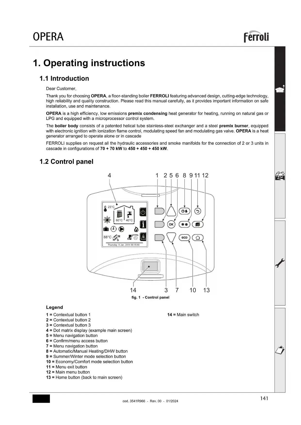
1.2 Control panel
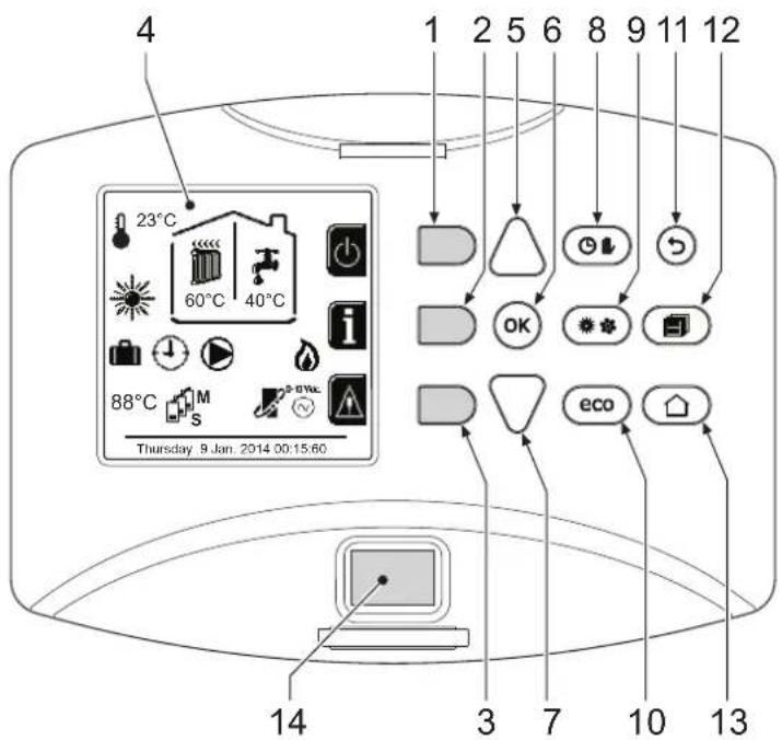
fig.1 - Control panel
Legend
1 = Contextual button 1
2 = Contextual button 2
3 = Contextual button 3
4 = Dot matrix display (example main screen)
5 = Menu navigation button
6 = Confirm/menu access button
7 = Menu navigation button
8 = Automatic/Manual Heating/DHW button
9 = Summer/Winter mode selection button
10 = Economy/Comfort mode selection button
11 = Menu exit button
12 = Main menu button
13 = Home button (back to main screen)
14 = Main switch
Contextual button
The contextual buttons (details 1, 2, 3 - fig. 1) are grey, with no screen print, and take on a different meaning depending on the menu selected. It is essential to observe the indication provided by the display (icons and text). In fig. 1 for example, using the contextual button 2 (detail 2 - fig. 1) it is possible access unit information such as: temperature of sensors, work power, etc.
Direct buttons
The direct buttons (details 8, 9, 10 - fig. 1) always have the same function.
Menu/observation buttons
The menu/Navigation buttons (details 5, 6, 7, 11, 12, 13 - fig. 1) are used to navigate among the various menus implemented in the control panel.
Menu structure
From the Home page, press the main Menu button (detail 12 - fig. 1).
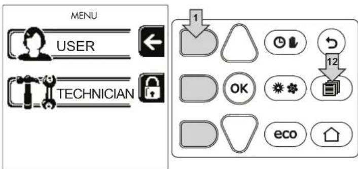
fig. 2
Access the "User" menu by pressing contextual button 1 (detail 1 - fig. 2). Then use the "menu navigation" buttons to access the different levels described in the following table.
| USER MENU | |||
| HEATING | |||
| Adjustment Temp | See fig. 13 | ||
| Reduction Adjustment Temp | See fig. 14 | ||
| Sliding Temperature | Curva1 | See fig. 28 | |
| Offset1 | See fig. 29 | ||
| Heating Off External Temp | See page 152 | ||
| Curva2 | / | ||
| Offset2 | / | ||
| Time Program menu | See "Time programming" on page 147 | ||
| DOMESTIC HOT WATER | |||
| Adjustment Temp | See fig. 15 | ||
| Reduction Adjustment Temp | See fig. 16 | ||
| Legionella | See "Legionella programming (with optional hot water tank installed)" on page 150 | ||
| Time Program | See "Time programming" on page 147 | ||
| VACATION FUNCTION | |||
| See "Holiday Function" on page 151 | |||
| MAINTENANCE | |||
| Test Mode | Test Mode | See fig. 64 | |
| Gas Type Selection | See fig. 63 | ||
| Cascade Test Mode | See " CASCADE TEST mode activation" on page 179 | ||
| Service Information | See "Service Information" on page 151 | ||
| Service Intervention Date | See "Service Intervention Date" on page 151 | ||
| SETTINGS | |||
| Language | See fig. 8 | ||
| Unit of measure | / | ||
| Date setting | See fig. 9 | ||
| Time setting | See fig. 10 | ||
Indication during operation
Heating
A heating request (generated by Room Thermostat or Remote Timer Control or 0-10 Vdc signal is indicated by activation of the circulating pump and by the hot air above the radiator (fig. 3).
"Heating only/Double circulating pump" configuration
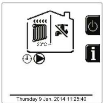
fig.3
"Circulating pump and 3-way valve" configuration
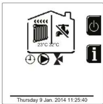
fig.4
DHW circuit (with optional hot water tank installed)
A hot water tank heating request is indicated by activation of the droplet under the faucet (fig. 5 and fig. 6).
"Double circulating pump" configuration
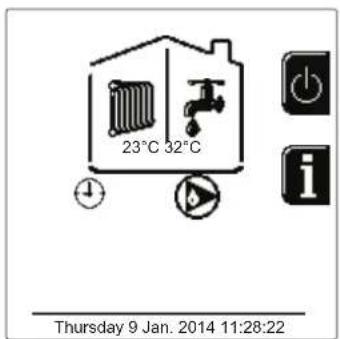
fig.5
"Circulating pump and 3-way valve" configuration
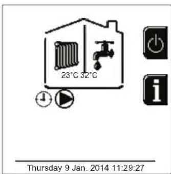
fig. 6
Exclude hot water tank (economy)
Hot water tank temperature maintaining/heating can be excluded by the user. If excluded, domestic hot water will not be delivered. The hot water tank can be deactivated by the user (ECO mode) by pressing the eco/comfort button (detail 10 - fig. 1). In ECO mode the display activates the symbol To activate COMFORT mode, press the eco/comfort button (detail 10 - fig. 1) again.
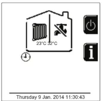
fig. 7-Economy
Information
From the main screen (Home), press the contextual button 2 (detail 2 - fig. 1). Then use the "Menu Navigation" buttons to display the following values:
| Heating demand | OT means OpenTherm control demand |
| TA means room thermostat demand | |
| 0-10Vdc means 0-10Vdc signal demand | |
| TA2 means second room thermostat demand | |
| Heating circulating pump ON/OFF | |
| Heating 3-way valve ON/OFF | |
| DHW 3-way valve ON/OFF | |
| Standby time ON/OFF | |
| T Delta protection ON/OFF | |
| Flame Supervisor ON/OFF | |
| Heating sensor1 °C | |
| Heating sensor2 °C | |
| Return sensor °C | |
| DHW sensor °C | |
| External probe | °C |
| Fume sensor °C | |
| Cascade heating sensor | °C |
| Fan frequency | Hz |
| Burner load | % |
| System water pressure | 1.4bar = ON, 0.0 bar = OFF |
| Modulating circulating pump | % |
| Cascade modulating circulating pump | % |
| Ionisation current | uA |
| Input 0-10Vdc | Vdc |
| Heating adjustment temperature | Setpoint (°C) |
| Power level adjustment 0-10Vdc | Setpoint (%) |
1.3 Lighting and shutdown
Boiler lighting
Press the On/Off button (detail 14 - fig. 1).
By pressing contextual button 1 it is possible to choose the desired language and confirm it with the "OK" button.
By pressing contextual button 3 it is possible to interrupt the FH mode.
If neither of the two choices described above is made, continue as follows.
- For the following 300 seconds the display will show FH which identifies the heating system air venting cycle.
- The display also shows the firmware version of the cards.
- Open the gas cock ahead of the boiler.
- When the message FH disappears, the boiler is ready to operate automatically in case of a room thermostat request.
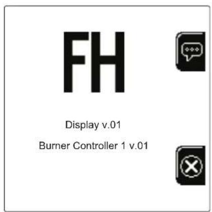
fig. 8-Boiler lighting


Settings
Contrast adjustment
To adjust the display contrast, press the contextual button 2 and the OK button together. Then press the button ref. 5 of fig. 1 to increase the contrast or the button ref. 7 of fig. 1 to decrease it.
Date and Time Adjustment
Reach the screen shown in fig. 9, navigating in the menu and following the path "USER MENU Settings" "Date Setting". Press navigation buttons 5 and 7 to select the value and modify it with contextual buttons 1 and 2. Confirm with the OK button.
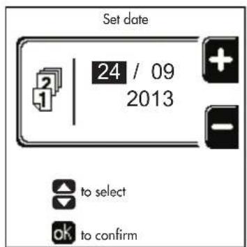
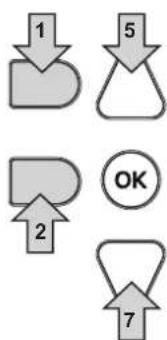
fig. 9- Date Adjustment
Reach the screen shown in fig. 10, navigating in the menu and following the path "USER MENU Settings" "Time Setting". Press navigation buttons 5 and 7 to select the value and modify it with contextual buttons 1 and 2. Confirm with the OK button.
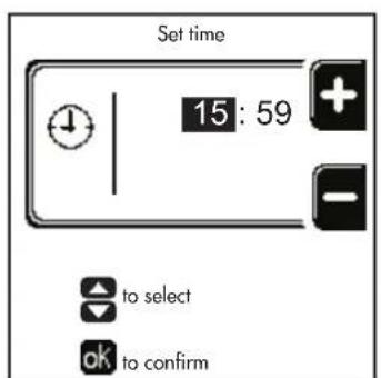
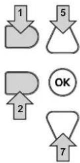
fig. 10-Time Adjustment
Boiler shutdown
From the main screen/Home, press the contextual button and confirm with the button. OK
When the boiler is turned off, the PCB is still powered.
Domestic hot water (with optional hot water tank installed) and heating operation are disabled. The frost protection system remains on.
To relight the boiler, press the contextual button again
The boiler will be immediately ready to operate whenever domestic hot water is drawn (with optional hot water tank installed) or in case of a room thermostat request.
To completely disconnect the unit from the power supply, press the button detail 14 fig. 1.
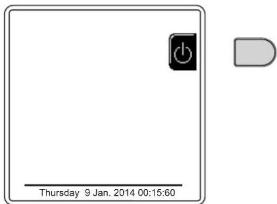
fig. 11- Turning the boiler off

The frost protection system does not work when the power and/or gas to the unit are turned off. To avoid damage caused by freezing during long shutdowns in winter, it is advisable to drain all water from the boiler, the DHW circuit and the heating system water; or drain just the DHW circuit and add a suitable antifreeze to the heating system, as prescribed in sec. 2.3.
1.4 Adjustments
Summer/Winter Swithover
Press the button (detail 9 - fig. 1) for 1 second.
The display activates the Summer symbol. The heating function is deactivated while possible DHW production remains active (with optional external hot water tank). The frost protection system remains on.
To deactivate Summer mode, press the button (detail 9 - fig. 1) again for 1 second.
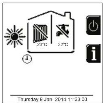
fig. 12- Summer
Heating temperature adjustment
Access the "Adjustment Temp" menu to vary the temperature from a minimum of Tmin to a maximum of Tmax. Confirm with the OK button.

The boiler comes with the time program not activated. Therefore, if requested, this is the setpoint value.
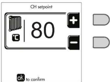
fig. 13
Heating temperature reduction
Access the "Reduction Adjustment Temp" menu to vary the temperature from a minimum of 0^ to a maximum of 50^ . Confirm with the OK button.

This parameter is used only if time programming is activated. See *** 'Time programming' on page 147 ***
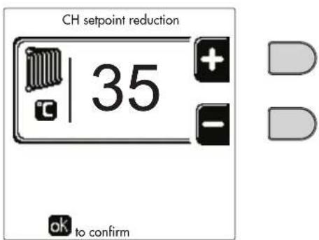
fig.14
DHW temperature adjustment (with optional hot water tank installed)
Access the "Adjustment Temp" menu to vary the temperature from a minimum of 10^ to a maximum of 65^ . Confirm with the OK button.

The boiler comes with the time program not activated. Therefore, if requested, this is the setpoint value.
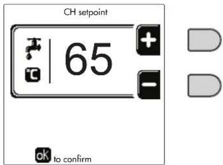
fig. 15
DHW temperature reduction (with optional hot water tank installed)
Access the "Reduction Adjustment Temp" menu to vary the temperature from a minimum of 0^ to a maximum of 50^ . Confirm with the OK button.

This parameter is used only if time programming is activated. See *** 'Time programming' on page 147 ***
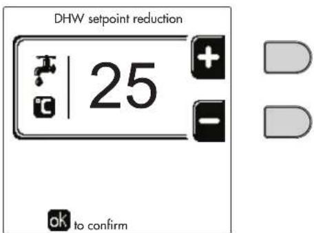
fig. 16
Time programming
Time programming is done in the same way both for heating and for DHW; the two programs are independent.
To program Heating, access the "Time Program" menu by following the path "USER MENU "HEATING" "Time Program".
To program DHW, access the "Time Program" menu by following the path "USER MENU "DOMESTIC HOT WATER" "Time Program".
Choose the type of programming to carry out and follow that described below. Select the day (fig. 17) or the interval of days to program (fig. 18) and confirm with the OK button.

fig.17
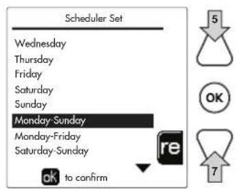
fig. 18
The program is weekly: this means that 6 independent time bands can be set for each day of the week (fig. 19); 4 options can be chosen for each time band:
ON. In case of a Heating/DHW request, the boiler works at the set Heating/DHW Adjustment Temperature (fig. 13/ fig. 15).
In case of a Heating/DHW request, the boiler works at the Reduced Adjustment Temperature. The Reduced temperature is obtained by subtracting the Reduction Adjustment Temperature (fig. 14/fig. 16) value from the set Heating/DHW Adjustment Temperature (fig. 13/fig. 15).
OFF. In case of a heating/DHW request, the boiler will not activate the Heating/DHW mode.
- --: -- OFF. Time band disabled.

The boiler comes with the time program not activated. In fact, every day will be programmed from 00:00 to 24:00h in ON mode (fig. 19).
First, set the start time of the first time band (fig. 19) using contextual buttons 1 and 2.
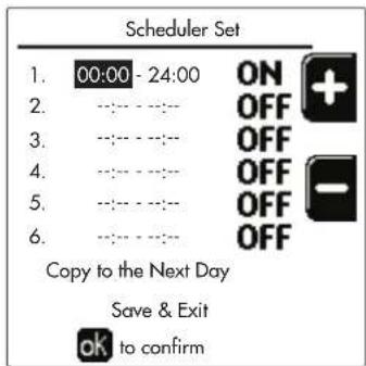
fig. 19
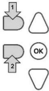
Press navigation button 7 to go to the end time of the first time band (fig. 20) and set it to the desired value using contextual buttons 1 and 2.
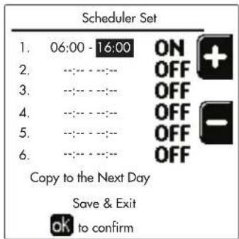
fig. 20

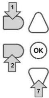
Press navigation button 7 and use contextual buttons 1 and 2 to set the work mode during the first time band (fig. 21)
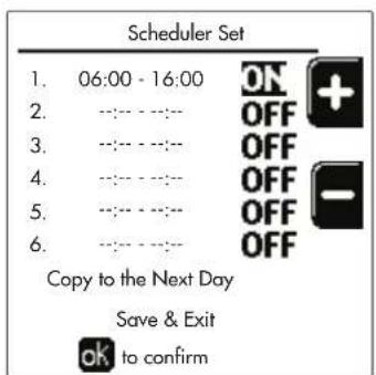
fig. 21
Then, press navigation button 7 to set (if necessary) the subsequent time bands (fig. 22, fig. 23 and fig. 24).
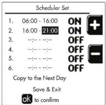

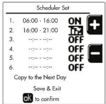

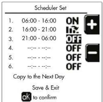
fig.22 fig.23
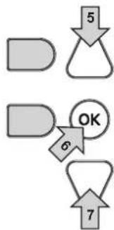
fig. 24
When the day has been programmed, press the OK button; the item "Save & Exit" will automatically be selected (fig. 25). Use navigation buttons 5 and 7 to modify the previous settings or press OK to confirm: in this case the display will return to showing the day (fig. 17) or the interval of days to be programmed (fig. 18). The same procedure can then be followed to complete the desired weekly program.
To program the following day in the same way, select "Copy to next day" and press OK to confirm (fig. 25).
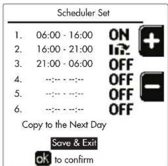
fig. 25

To restore the time program to the factory values, press contextual button 3 in the Time Program menu (fig. 26) and confirm with OK.
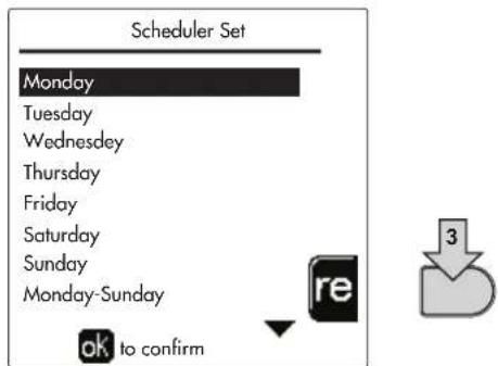
fig. 26
The two Heating and DHW hourly programs are independent even in case of Reset to factory value. Legionella programming (with optional hot water tank installed)
To enable the Anti-Legionella Function it is necessary to set parameter P23, within the "TECHNICAL MENU", to ON. To program the function it is necessary to access the "Legionella" menu via the path "USER MENU" "DOMESTIC HOT WATER" "Legionella".
In this menu it is possible to set the following options:
- Anti-Legionella day. Defines the day of the week during which the function will be activated. The function can only be activated once a week.
- Anti-Legendella time of day. Defines the start time of the function.
- Anti-Legionella duration. Defines the duration (in minutes) of the function.
- Anti-Legionella Adjustment Temp. Defines the DHW Adjustment temperature during the function.
ATTENTION In ECO m
In ECO mode the function is not active.
- The Anti-Legionella Function will only be active if the boiler is set to "Automatic" mode" (O) and only in the time bands set to ON or to "Reduced temperature"
Otherwise, in the time bands set to OFF, the function will not be activated, even if set.
- In vacation mode ( ) the Anti-Legionella Function is active.
- If the Anti-Legionella Function is not carried out correctly, the message shown in fig. 27 is displayed. Even in the presence of this message, the boiler will continue to operate correctly.
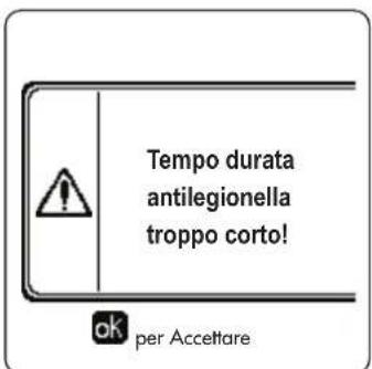
fig. 27- Message Anti-legionella function not completed

The temperature set via the "Anti-Legionella Adjustment Temp." menu must NOT be higher than the maximum DHW adjustment temperature set via parameter P19 within the TECHNICAL MENU.

If a circulating pump is installed in the system, for water circulation during the Anti-Legionella Function, parameter b08 must be set to 1. In this way the contact between terminals 9-10 (ref. 300 - fig. 95, fig. 96 and fig. 97) closes when the function is activated.
Holiday Function
Access the "HOLIDAY FUNCTION" menu through the path "USER MENU HOLIDAY FUNCTION" to set:
- Holiday start date.
- Holiday end date.
The display can activate two types of icons:
- The Holiday function is programmed but not yet active.
- The Holiday function is in progress. The boiler will behave as if Summer mode and Economy mode were active (with optional hot water tank installed).
The frost protection and Legionella functions will remain active (if activated).
Service Intervention Date
This informs when the alert of programmed maintenance by the technician will be activated. It does not represent an alarm or a fault but just a notice. After that date, whenever the Main menu is accessed, the boiler will activate a screen indicating that programmed maintenance is due.
Service Information
This information shows the telephone number to contact in case of assistance (if programmed by the technician).
Room temperature adjustment (with optional room thermostat)
Using the room thermostat, set the temperature required in the rooms.
Room temperature adjustment (with optional remote timer control)
Using the remote timer control, set the temperature desired in the rooms. The boiler unit will set the system water according to the required room temperature. For information on the remote timer control, please refer to its user's manual.
Sliding Temperature
When the external probe (optional) is installed, the relevant external temperature symbol is activated on the control panel display. The boiler control system works with "Sliding Temperature". In this mode, the heating system temperature is regulated according to weather conditions, to ensure high comfort and energy efficiency throughout the year. In particular, as the outside temperature increases the system flow temperature decreases according to a specific "compensation curve".
With Sliding Temperature adjustment, the "Heating adjustment" temperature becomes the maximum system flow temperature. It is advisable to set a maximum value to allow system adjustment throughout its useful operating range.
The boiler must be adjusted at the time of installation by qualified personnel. The user can still make further adjustments for better comfort.
Compensation curve and curve offset
Access the Sliding Temperature menu. Adjust the desired curve from 1 to 10 according to the characteristic (fig. 30) via the parameter "Curve1" and confirm with the OK button.
By setting the curve to 0, the sliding temperature adjustment is disabled.
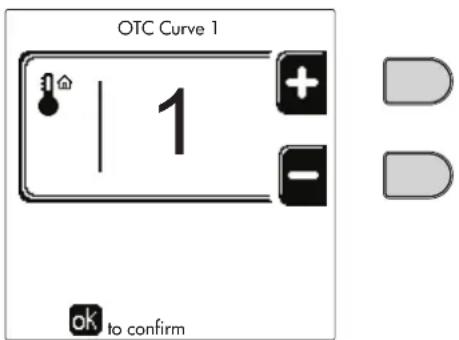
fig. 28- Compensation curve
Adjust the parallel offset of the curves from 20 to 60^ (fig. 31), via the parameter "Offset1" and confirm with the OK button.
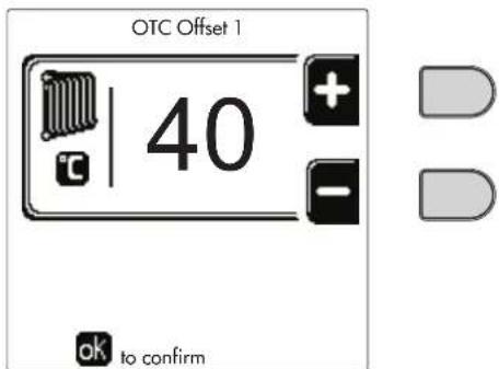
fig. 29- Parallel curve offset
If the room temperature is lower than the desired value, it is advisable to set a higher order curve and vice versa. Proceed by increasing or decreasing in steps of one and check the result in the room.
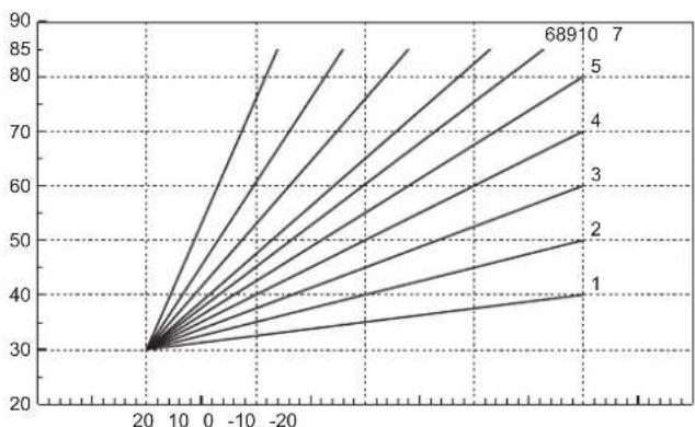
fig. 30- Compensation curves
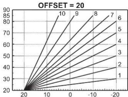
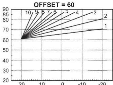
fig. 31- Example of compensation parallel curve offset

This parameter is used only if the time programming has been activated. See *** 'Time programming' on page 147 ***
Outside Temperature Heating OFF
Access the "Out Temp Heat Off' to activate the function: between 7^ and 30^
If activated, this function will deactivate the heating demand whenever the temperature measured by the external probe is higher than the programmed value.
The heating demand will be reactivated as soon as the temperature measured by the external probe is lower than the programmed value.
Adjustments from remote timer control

If the boiler is connected to the Remote Timer Control (optional), the previously described adjustments are managed as described in table 1.
Table 1
| Heating temperature adjustment | Adjustment can be made from the Remote Timer Control menu and the boiler control panel. |
| DHW temperature adjustment (with optional hot water tank installed) | Adjustment can be made from the Remote Timer Control menu and the boiler control panel. |
| Summer/Winter Swithover | Summer mode has priority over a possible Remote Timer Control heating request. |
| Eco/Comfort selection (with optional hot water tank installed) | On disabling DHW from the Remote Timer Control menu, the boiler selects Economy mode. In this condition, the button detail 10 - fig. 1 on the boiler panel, is disabled. |
| By enabling DHW from the Remote Timer Control menu, the boiler selects Comfort mode. In this condition, use the button detail 10 - fig. 1 on the boiler panel to select one of the two modes. | |
| Sliding Temperature | Both the Remote Timer Control and the boiler card manage the Sliding Temperature adjust-ment: between the two, the Sliding Temperature of the boiler card has priority. |
System water pressure adjustment
The filling pressure with the system cold must be approx. 1.0 bar. If the system pressure falls to values below minimum, the boiler card will activate fault 37 and the number of the module (fig. 32).

Once the system pressure is restored, the boiler will activate the 300-second air venting cycle indicated on the display by FH.
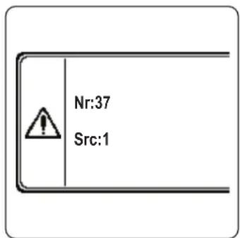
fig. 32- Module 1 insufficient system pressure fault
2. Installation
2.1 General Instructions
THE BOILER MUST ONLY BE INSTALLED BY QUALIFIED PERSONNEL, IN COMPLIANCE WITH ALL THE INSTRUCTIONS GIVEN IN THIS TECHNICAL MANUAL, THE CURRENT PROVISIONS OF LAW, THE NATIONAL AND LOCAL REGULATIONS, AND THE RULES OF PROPER WORKMANSHIP.
For Switzerland, the following installation regulations and directives must be applied:
- SVGW - gas principles G1: installation Gas
- EKAS - Form. 1942: liquid gas directive, part 2
- Cantonal laws and regulations (e.g. fire safety regulations)
OPERAs is a heat generator arranged to operate alone or in cascade (bank).
FERROLI supplies on request all the hydraulic accessories and smoke manifolds for the connection of 2 or 3 units in cascade in configurations of 70 + 70kW to 450 + 450 + 450kW .
When OPERA generators are installed in cascade with the accessories foreseen by FERROLI, all the requirements of current laws and regulations applicable to such "equivalent" generator of total thermal capacity must be met. In particular the place of installation, safety devices and fume exhaust system must be adequate for the total heating capacity of the bank of units. The instructions given in this manual concern both the single unit and the connection in cascade. For further information regarding installation of the generators in cascade, refer to the specific manual supplied with the cascade connection kits.

The boiler electronics are equipped with management functions for a cascade of up to 6 units. To create cascade systems with more than three units without using the accessories foreseen by FERROLI, suitably sized hydraulic/gas manifolds must be arranged, complete with all the safety devices required by current regulations, as well as individual fume exhausts or fume manifolds appropriately sized by a qualified technician.
2.2 Place of installation
The generator must be installed in a suitable room with ventilation openings towards the outside in conformity with current regulations. If there are several burners or exhausters that can work together in the same room, the ventilation openings must be sized for simultaneous operation of all the units. The place of installation must be free of flammable materials or objects, corrosive gases, powders or volatile substances. The room must be dry and not exposed to rain, snow or frost. For positioning, leave sufficient room around the unit for normal maintenance operations. In particular, check that the burner door can open freely.
2.3 Plumbing connections
The heating capacity of the unit must be previously established by calculating the building's heat requirement according to current regulations. The system must be provided with all the components for correct and regular operation. In particular, provide for all the protection and safety devices required by current regulations for the complete modular generator. They must be installed on the hot water circuit flow piping, immediately after the last module, within a distance of not more than 0.5m and with no shutoff devices in between. The unit is not supplied with an expansion tank or safety valve; their connection must therefore be carried out by the Installer.
This unit can operate correctly also with a minimum flow rate of 0 l/h and does not require post-circulation to eliminate the thermal inertia. With reference to par. "3.3. R3F file R edition 2009" the post-circulation time prescribed by the manufacturer is therefore equal to 0 seconds.

The safety valve outlet must be connected to a funnel or collection pipe to prevent water spurting onto the floor in case of overpressure in the heating circuit. Otherwise, if the discharge valve cuts in and floods the room, the boiler manufacturer cannot be held liable.
Do not use the water system pipes to ground electrical appliances.

Before installation, flush all the pipes of the system thoroughly to remove any residuals or impurities that could affect proper operation of the unit. Use chemical conditioners suitable for the purpose; i.e. able to remove from the walls and bottom of the pipes and the various components of the system, sludge, metal
oxides and, in low temperature systems, also biomass, with just the circulation of the water, with system hot and/or cold. The products used must not be corrosive and/or aggressive for metals and plastics and must not significantly alter the natural pH of the water.

Also, a filter must be installed on the system return piping to prevent impurities or sludge from the system clogging and damaging the heat generators.
The filter must be installed when replacing generators in existing systems. The manufacturer declines any liability for damage caused to the generator by failure to install or inadequate installation of this filter.
Carry out the relevant connections according to the diagram in sec. 4.1 and the symbols on the unit.
Table 2- SIZE OF CONNECTIONS
| MODEL 70 125 | 160 220 | 320 450 | |||
| System flow 1" 1/4 threaded 1" 1/4 threaded 2" | threaded DN65 flanged DN65 flanged | ||||
| Main system return / LOW TEMPERATURE 1" | 1/4 threaded 1" 1/4 threaded 2" threaded | ed DN65 flanged DN65 flanged | |||
| Gas inlet 3/4" threaded 1" threaded 1" | 1" 1/4 threaded 1" | 1/2 threaded | |||
In case of installation in bank, the water circuit of each boiler must be fitted with a motor-operated shutoff valve (controlled by the unit, see wiring diagram fig. 95) that prevents reverse circulation with the boiler not working.
A single safety valve must also be provided for each boiler in accordance with the requirements of "file R".
The following optional kits are available for this purpose:
052000X0 - MOTOR-OPERATED BUTTERFLY VALVE DN50
052001X0 - MOTOR-OPERATED BUTTERFLY VALVE DN65
If the distribution system adjustment is independent of the electronics of the generators, the creation of a bypass between the flow manifold and that of the system return is advisable in order to protect the circulating pumps.
System water characteristics
Before installing the OPERA generator, the new or existing system must be properly cleaned in order to eliminate installation residues, solvents, sludge and contaminants in general that may compromise the effectiveness of the protective conditioning treatments. Use neutral cleaning products that do not attack metals, rubber and plastic parts of the generator/system. Empty, wash and recharge the system in compliance with the following instructions. A dirty system will not guarantee the life of the generator over time, even with the use of protective conditioners.

OPERA boilers are suitable for installation in heating systems with non-significant entry of oxygen (ref. systems "case I" EN14868). A physical separator (e.g. plate heat exchanger) must be provided in systems with continuous entry of oxygen (e.g. underfloor systems without anti-diffusion pipes or open vessel), or frequent (frequent water replenishment).
The water in a heating system must be treated in compliance with the laws and regulations in force, have the characteristics required by UNI 8065, and comply with the provisions of EN14868 (protection of metallic materials against corrosion).
The filling water (first filling and subsequent replenishments) must be potable, clear, with hardness under the values indicated in the table below and treated and conditioned with chemical conditioners declared suitable by the maker (see following list), in order to prevent encrustations, corrosive or aggressive phenomena on the metals and plastics of the generator and system, the formation of gas, and the proliferation of bacterial or microbial masses in low temperature systems.
The water contained in the system, as well as the replenishment water, must be checked periodically (at every start-up of the system, after any non-scheduled intervention such as, for example, replacement of the generator or other system components, as well as at least once a year during mandatory routine maintenance operations as required by UNI 8065). The water must have a clear appearance and respect the limits given in the following table.
| EXISTING SYSTEM NEW SYSTEM | ||
| WATER PARAMETER | ||
| Total filling water hardness (°f) <10 <10 | ||
| Total system water hardness (°f) <15 <10 | ||
| PH 7 < Ph < 8.5 | ||
| Copper Cu (mg/l) Cu < 0.5 mg/l | ||
| Iron Fe (mg/l) Fe < 0.5 mg/l | ||
| Chlorides (mg/l) Cl < 50 mg/l | ||
| Conductivity (μS/cm) < 600 μS/cm* | ||
| Sulfates < 100 mg/l | ||
| Nitrates < 100 mg/l | ||
- In the presence of conditioners, the limit increases to 1200 S/cm .
In case of differing values or difficult verification of values with conventional analysis/testing procedures, contact the company for additional evaluations. The conditions of the feed water to be treated can vary even significantly depending on the geographical areas where the systems are located.
Chemical conditioners deoxygenating, anti-scaling, corrosion inhibiting, anti-bacterial, anti-algae, frost protection, PH correction products, etc., must also be suitable for the materials of the generator and system. They must be put in the system respecting the quantity indicated by the supplier of the chemical product and verified in their concentration.

A chemical conditioner in insufficient concentration will not be able to ensure the required protection.
Always check the product concentration each time it is added and cyclically, at least once a year, using qualified technical personnel such as our authorized technical assistance network.
Table 3- Chemical conditioners declared suitable and available at our network of Authorized Technical Assistance Centers
| Description | Sentinel type alternative products | |
| LIFE PLUS/B - MOLY - MOLY K | Molybdenum-based corrosion inhibitor | X100 |
| LIFE DUE | Noise reduction/anti-scaling maintenance | X200 |
| BIO KILL | Biocidal anti-algae | X700 |
| PROGLI | Propylene frost protection | X500 |
| Products with equivalent characteristics may be used | ||
The unit is equipped with a frost protection system that activates the boiler in heating mode when the system delivery water temperature falls below 6^ . The device is not active if the power and/or gas supply to the unit is turned off. If necessary, for system protection use a suitable anti-freeze liquid that meets the same requirements as set out above and provided for by UNI 8065.
In the presence of adequate chemical/physical system and feed water treatments and related high cyclicity controls able to ensure the required parameters, for industrial process applications the product can be installed in open-vessel systems with vessel hydrostatic height able to ensure compliance with the minimum operating pressure indicated in the product technical specifications.
To ensure the reliability and correct operation of the boilers, always install a mechanical filter in the loading circuit and, in the system, a dirt separator (possibly magnetic) and a deaerator as required by the UNI 8065 as well as a volumetric meter on the system replenishment line.

Failure to comply with the provisions of this paragraph, "System water features", will involve non-recognition of the warranty and damage due to such shortcomings.
Combustion chamber maintenance
To ensure the efficiency and reliability of the generator over time, it is very important to contact our authorized technical assistance service, at least once a year, for routine maintenance operations and also for checking the combustion chamber and, if necessary, its cleaning. In this regard we recommend the use of the following products, checked and tested on our exchangers and available at our Authorized Technical Assistance Centers.
Table 4- Products declared suitable and available at our network of Authorized Technical Assistance Centers
| Description |
| BIO INF Liquid product for cleaning steel combustion chambers |
| Products with equivalent characteristics may be used |
Given the aggressiveness of the chemical products for combustion chambers, always rely only and exclusively on qualified personnel and make safe the sensitive elements, such as the electrodes, insulating materials, etc., that could become damaged by direct contact with the product. Rinse well after each heat exchanger cleaning process (product application time 15-20 minutes) and repeat the operation as required.

Irrespective of the chemical products used, always make use of qualified technical personnel such as our authorized technical assistance network and manage the technological fluids according to the applicable local laws, rules and regulations.
Hydraulic circuit examples
In the examples described below, the checking/change of some parameters may be required.
To do this it is necessary to access the Technical menu.
From the Home page, press the main Menu button (detail 12 - fig. 1).
Access the "Technical" menu by pressing contextual button 2 (detail 2 - fig. 1).
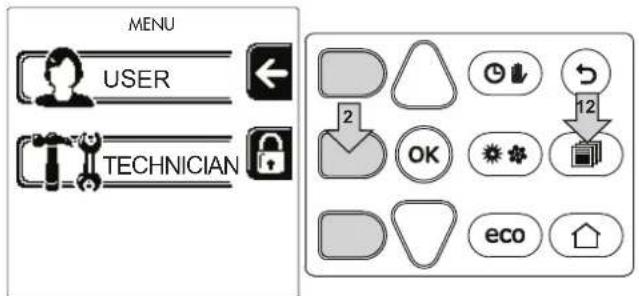
fig. 33
Enter the code "4 1 8" with contextual buttons 1 and 2. Confirm each number with the OK button.
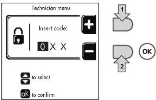
fig. 34
Access the Parameters menu by pressing the OK button.
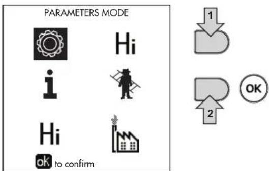
fig. 35
Access the "Configuration Menu" or "System Type Menu" according to the parameter to be modified as given in each hydraulic circuit example.
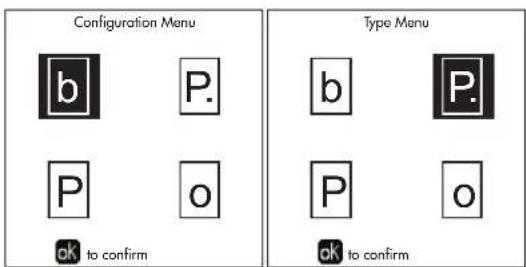
fig. 36
Two direct heating circuits
- Schematic diagram
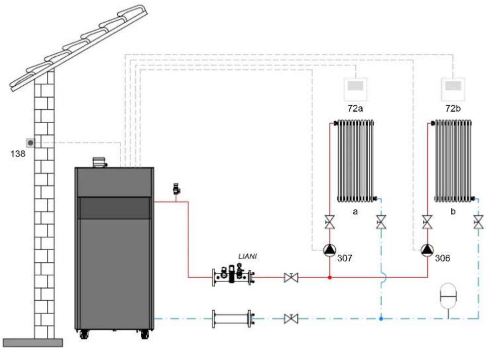
fig.37
- Electrical connections
After installation, carry out the necessary electrical connections as shown in the wiring diagram. Then configure the controller as described in the specific section.
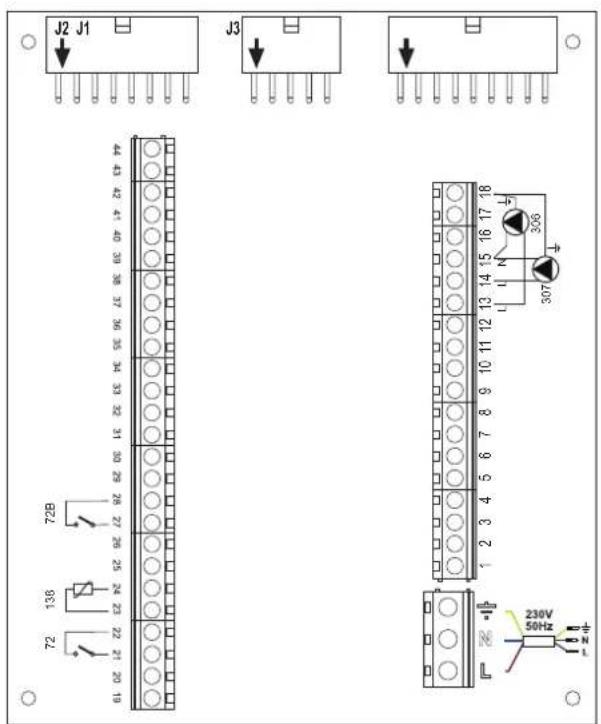
fig. 38
Legend (fig. 37 and fig. 38)
72 1st zone (direct) room thermostat
72b 2nd zone (direct) room thermostat
138 External probe
307 1st zone (direct) circulating pump
306 2nd zone (direct) circulating pump
a 1st zone (direct)
b 2nd zone (direct)
M Flow
R Return
I* ISPESL safety devices (when required - not supplied)
To manage the sliding temperature it is necessary to purchase the external probe accessory code 013018X0
- Parameters
Each system requires a different parameterisation. Follow the access procedure given below.
"System Type Menu"
Change parameter P.01 of the "System Type Menu" to 4.
Change parameter P.09 of the "System Type Menu" to 1.
- Optional features
In addition to the electrical connections of the previous figure (necessary for this system configuration) there are options that do not require settings.
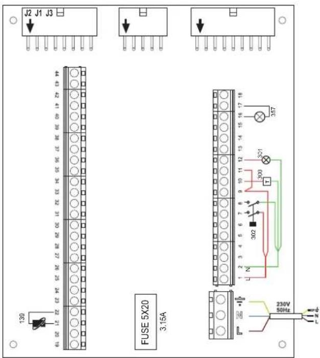
fig. 39
Legend (fig. 39)
139 Remote control: it can be installed instead of 72 to manage the request of the 1st zone (direct)
300 Burner on indication (voltage-free contact output): the example shows the connection of a 230 Vac hour meter
301 Fault indication (voltage-free contact output): the example shows the connection of a 230Vac lamp
302 Remote reset input (230Vac): the example shows the connection of a double-pole switch at 230Vac, allowing the resetting of a block type fault
357 Fault indication (230Vac): the example shows the connection of a 230Vac lamp
One direct heating circuit and one DHW circuit with circulating pump
- Schematic diagram
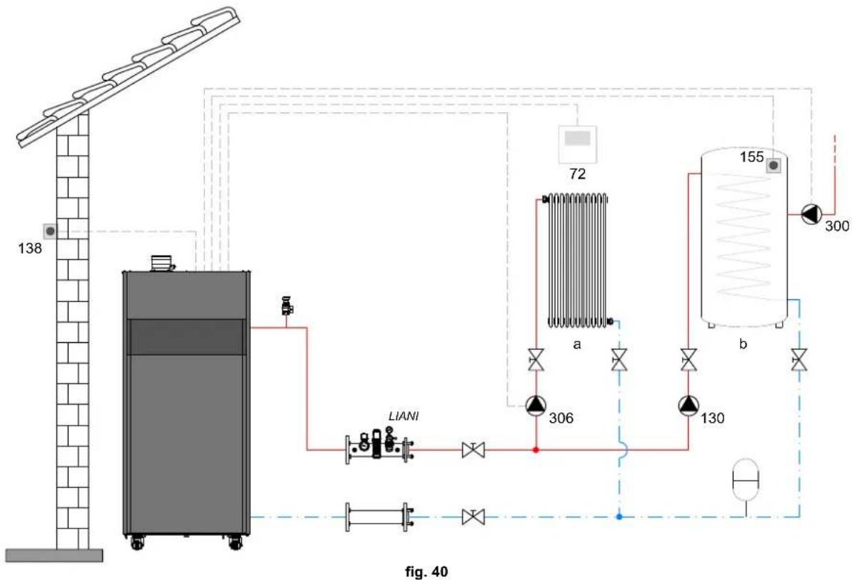
- Electrical connections
After installation, carry out the necessary electrical connections as shown in the wiring diagram. Then configure the controller as described in the specific section.
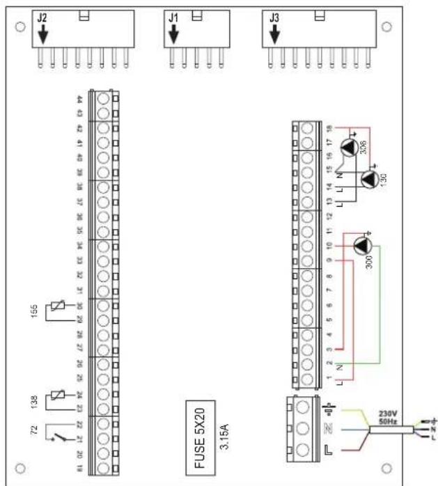
fig. 41
Legend (fig. 40 and fig. 41)
72 1st zone (direct) room thermostat
130 Hot water tank circulating pump
138 External probe
155 Hot water tank probe
300 Anti-Legionella circulating pump
306 1st zone (direct) circulating pump
a 1st zone (direct)
b Hot water tank circuit
M Flow
R Return
I* ISPESL safety devices (when required - not supplied)
To manage the sliding temperature it is necessary to purchase the external probe accessory code 013018X0
If a hot water tank probe (not supplied) is used, it is necessary to purchase the NTC probe accessory code 1KWMA11W (2 mt.) or code 043005X0 (5 mt.)
If a hot water tank thermostat (not supplied) is used, it is necessary to purchase the accessory kit code 013017X0 (to be connected in place of the Hot Water Tank Probe)
- Parameters
Each system requires a different parameterisation. Follow the access procedure given below.
"Service Menu"
Check/change parameter b02 of the "Transparent Parameters Menu" to 8 (for models 70, 125 and 320) and to 5 (for model 220)
Check/change parameter b08 of the "Transparent Parameters Menu" to 1
"System Type Menu"
Change parameter P.09 of the "System Type Menu" to 1.
- Optional features
In addition to the electrical connections of the previous figure (necessary for this system configuration) there are options that do not require settings.
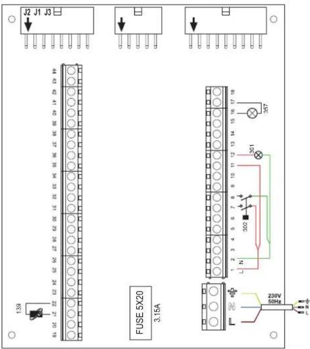
fig. 42
Legend (fig. 42)
139 Remote control: it can be installed instead of 72 to manage the request of the 1st zone (direct)
301 Fault indication (voltage-free contact output): the example shows the connection of a 230Vac lamp
302 Remote reset input (230Vac): the example shows the connection of a double-pole switch at 230Vac, allowing the resetting of a block type fault
357 Fault indication (230Vac): the example shows the connection of a 230Vac lamp
A direct heating circuit and a DHW circuit with diverter valve (3-wire)
- Schematic diagram
Use diverter valves with 3 wires: OPENING PHASE 230V - CLOSING PHASE 230V - NEUTRAL with switching times (from fully closed to fully open) not exceeding 90 seconds
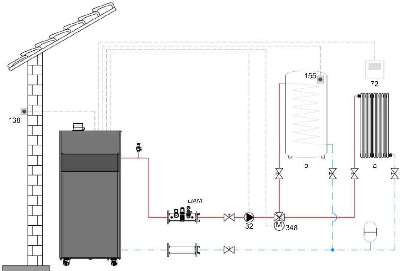
fig. 43
Legend (fig. 43 and fig. 44)
32 Heating circulating pump
72 1st zone (direct) room thermostat
138 External probe
155 Hot water tank probe
348 3-way valve (3-wire)
A = OPENING PHASE
B = NEUTRAL
C = CLOSING PHASE
a 1st zone (direct)
b Hot water tank circuit
M Flow
R Return
^ ISPESL safety devices (When required - Not supplied)
- Electrical connections
After installation, carry out the necessary electrical connections as shown in the wiring diagram.
Then configure the controller as described in the specific section.

To avoid damaging the board, it is advisable to use external relays to control the 3-way valve, as indicated in fig. 44.
To manage the sliding temperature it is necessary to purchase the external probe accessory code 013018X0 If a hot water tank probe (not supplied) is used, it is necessary to purchase the NTC probe accessory cod 1KWMA11W (2 mt.) or code 043005X0 (5 mt.)
If a hot water tank thermostat (not supplied) is used, it is necessary to purchase the accessory kit code 013017X0 (to be connected in place of the Hot Water Tank Probe)
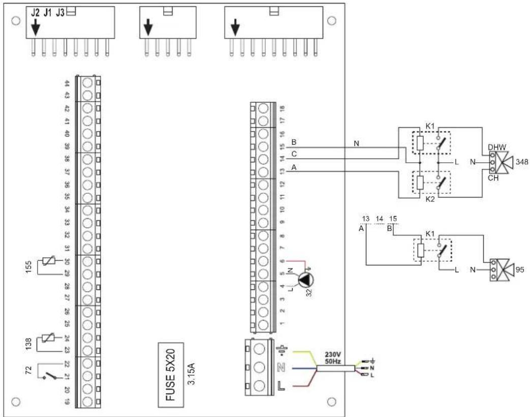
fig. 44
- Parameters
Each system requires a different parameterisation. Follow the access procedure given below.
"Service Menu"
Check/change parameter b02 of the "Transparent Parameters Menu" to 9 (for models 70, 125 and 320) and to 6 (for model 220).
- Optional features
In addition to the electrical connections of the previous figure (necessary for this system configuration) there are options that do not require settings.
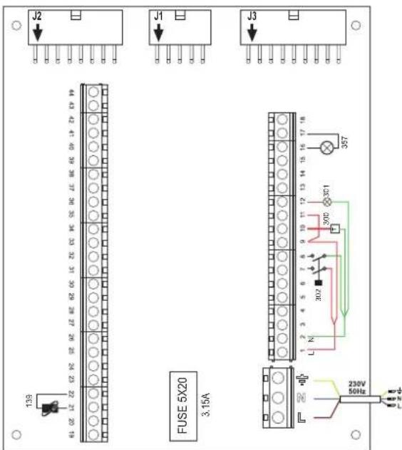
fig. 45
Legend (fig. 45)
139 Remote control: it can be installed instead of 72 to manage the request of the 1st zone (direct)
300 Burner on indication (voltage-free contact output): the example shows the connection of a 230Vac hour meter
301 Fault indication (voltage-free contact output): the example shows the connection of a 230Vac lamp
302 Remote reset input (230Vac): the example shows the connection of a double-pole switch at 230Vac, allowing the resetting of a block type fault
357 Fault indication (230Vac): the example shows the connection of a 230Vac lamp
Two mixed heating circuits, one direct heating circuit and one DHW circuit with circulating pump
- Schematic diagram
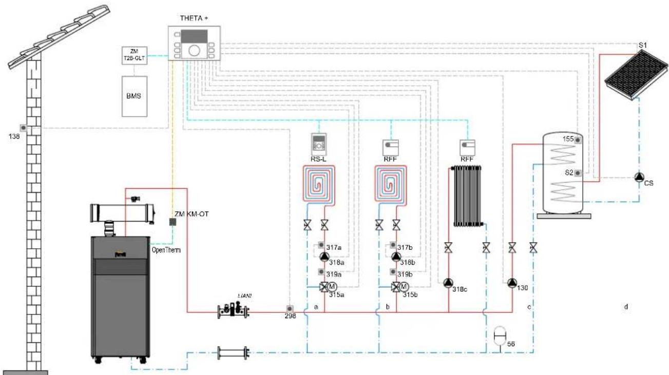
fig. 46
Legend (fig. 46 and fig. 47)
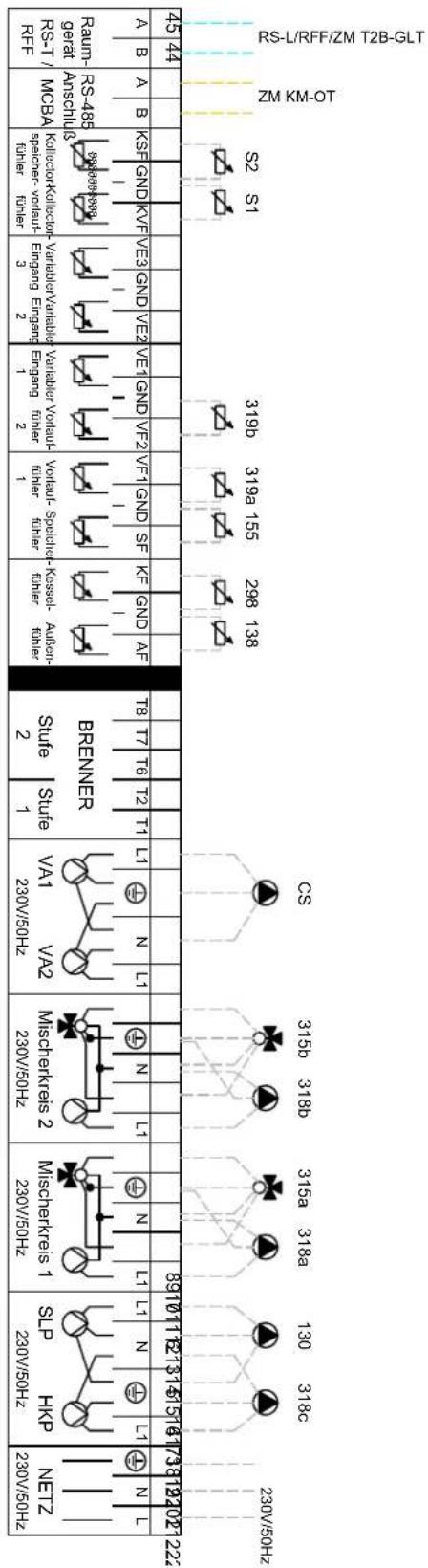
THETA+Central temperature control unit and cascade manager
ZM KM-OTModule for cascade management and communication between the generator and the THETA + unit via Open Therm
RS-L Room unit
RFF Room probe
ZM T2B-GLTInterface with BMS systems
BMS Building Management System
a Low temperature mixed zone
b Low temperature mixed zone
c High temperature direct zone
d DHW production with double coil storage
CS Solar circulating pump
S1 Solar field flow sensor (PT 1000)
S2 Storage tank temperature probe (supplied as standard with THETA+)
INAILINAIL safety devices branch.
56 Expansion vessel
130 DHW storage tank filling pump
138 138 External probe (supplied as standard with THETA +
155 Storage tank probe (supplied as standard with THETA +
298 System flow manifold probe (supplied as standard with THETA+)
315 a/bMotorized mixer valve
317 a/bSafety thermostat
318 a/b/c Heating system circulating pump
319 a/bMixed zone flow probe (supplied as standard with THETA+)
- Electrical connections
After installation, carry out the necessary electrical connections as shown in the wiring diagram.
Then configure the controller as described in the specific section.
NOISNELVSSV8 -A0E2
ENOISNE⊥A
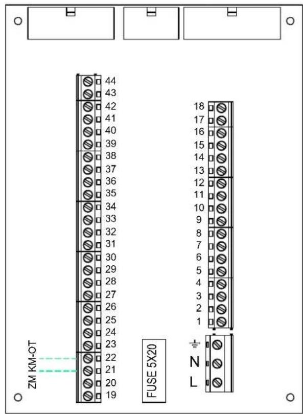
fig. 47
- Parameters
To parameterize the "THETA+" thermoregulation, consult the manual supplied with the kit.
- Optional features
In addition to the electrical connections of the previous figure (necessary for this system configuration) there are options that do not require settings.
Legend (fig. 48)
301 Fault indication (voltage-free contact output): the example shows the connection of a 230Vac lamp
302 Remote reset input (230Vac): the example shows the connection of a double-pole switch at 230Vac, allowing the resetting of a block type fault
357 Fault indication (230Vac): the example shows the connection of a 230Vac lamp
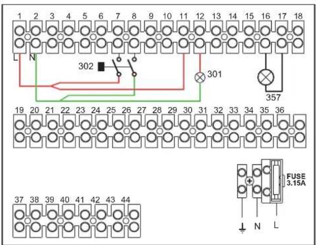
fig. 48
Generators in cascade: a direct heating circuit and a DHW circuit with circulating pump
Schematic diagram
The boiler electronics can manage up to a maximum of 6 modules. 3 are given in the example.
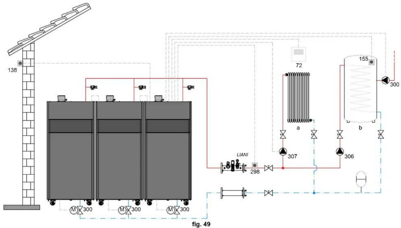
Legend (fig. 49 and fig. 50)
72 1st zone (direct) room thermostat
130 Hot water tank circulating pump
138 External probe
155 Hot water tank probe
298 Cascade temperature sensor
300MMASTER boiler motorized butterfly valve
A = OPENING PHASE
B = NEUTRAL
C = CLOSING PHASE
300S SLAVE boiler motorized butterfly valve
A = OPENING PHASE
B = NEUTRAL
C = CLOSING PHASE
306 1st zone (direct) circulating pump
a 1st zone (direct)
b Hot water tank circuit
M Flow
R Return
I* ISPESL safety devices (when required - not supplied)
To manage the sliding temperature it is necessary to purchase the external probe accessory code 013018X0
If a hot water tank probe (not supplied) is used, it is necessary to purchase the NTC probe accessory code 1KWMA11W (2 mt.) or code 043005X0 (5 mt.)
If a hot water tank thermostat (not supplied) is used, it is necessary to purchase the accessory kit code 013017X0 (to be connected in place of the Hot Water Tank Probe)
If a cascade probe (not supplied) is used, it is necessary to purchase the accessory NTC probe code 1KWMA11W (2 mt.) or code 043005X0 (5 mt.)
- Electrical connections
After installation, carry out the necessary electrical connections as shown in the wiring diagram.
Then configure the controller as described in the specific section.
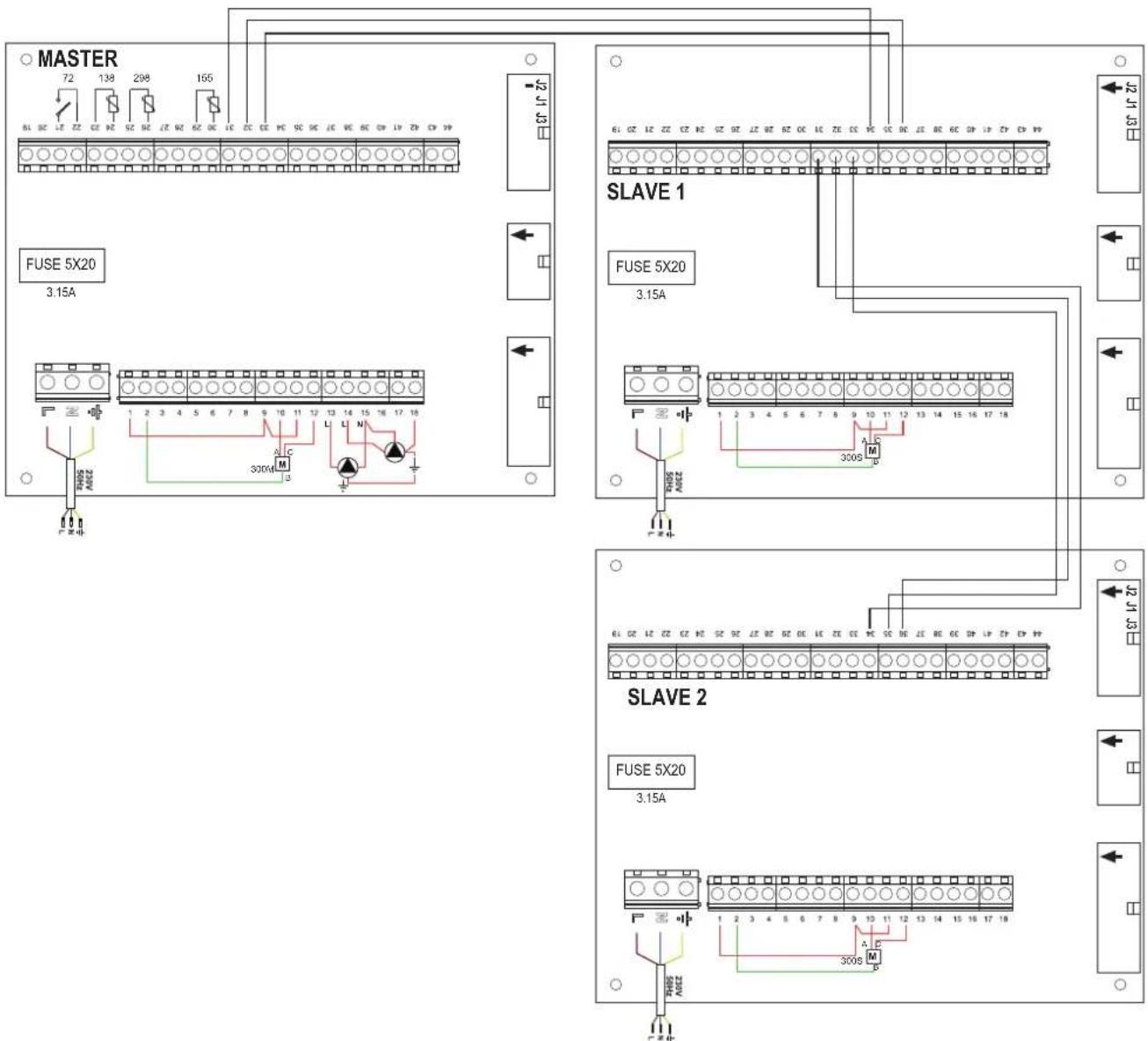
fig. 50
Parameters
Each system requires a different parameterisation. Follow the access procedure given below, for the MASTER as well as SLAVE boilers.
"Service Menu"
Check/Change parameter P02 of the "Transparent Parameters Menu" to 8. (for models 70, 125 and 320) and to 5 (for model 220)
Check/Change parameter b08 of the "Transparent Parameters Menu" to 3.
"System Type Menu"
Change parameter P.02 of the "System Type Menu" to 1.
Change parameter P.09 of the "System Type Menu" to 1.
- Optional features
In addition to the electrical connections of the previous figure (necessary for this system configuration) there are options that do not require settings.
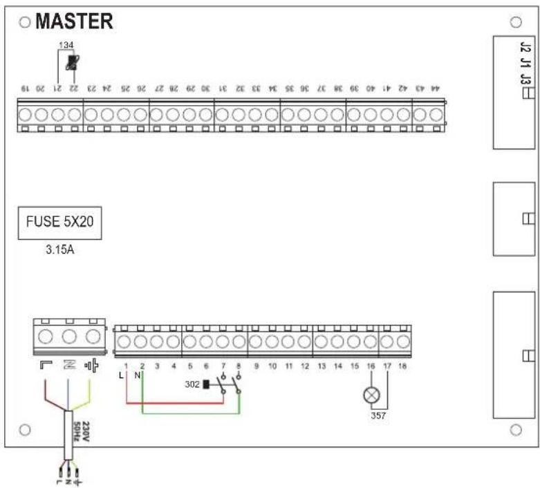
fig. 51-MASTER
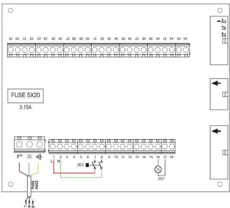
fig. 52-SLAVE
Legend (fig. 51 and fig. 52)
139 Remote control: it can be installed instead of 72 to manage the request of the 1st zone (direct)
302 Remote reset input (230Vac): the example shows the connection of a double-pole switch at 230Vac, allowing the resetting of a block type fault
357 Fault indication (230Vac): the example shows the connection of a 230Vac lamp
2.4 Gas connection

Before making the connection, make sure the unit is arranged for operation with the type of fuel available and carefully clean all the pipes of the gas system to remove any residues that could affect proper functioning of the boiler.
The gas must be connected to the relevant connection (see fig. 74, fig. 77, fig. 80, fig. 81 and fig. 84) in conformity with the current regulations, using a continuous-surface stainless steel hose, placing a gas cock between the system and the boiler.

To allow easy opening of the burner door during periodic maintenance, the last section of the connection between the system and the unit must have a continuous-surface stainless steel hose.
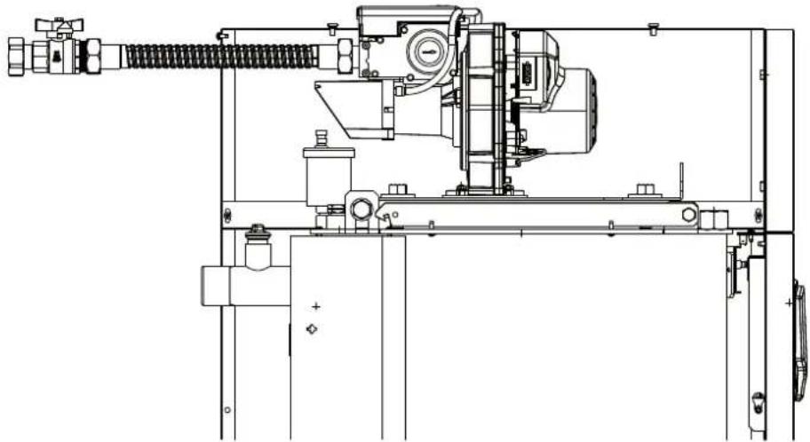
fig. 53
Make sure that all gas connections are tight. The capacity of the gas meter must be sufficient for the simultaneous use of all units connected to it. The diameter of the gas pipe leaving the boiler is not decisive for choosing the diameter of the pipe between the unit and the meter; it must be chosen according to its length and pressure losses, in conformity with the current regulations.

Do not use the gas pipes to earth electrical appliances.
In case of connection in cascade, make sure to install a fuel shutoff valve externally with respect to the modules.
2.5 Electrical connections
Connection to the electrical grid

The unit's electrical safety is only guaranteed when correctly connected to an efficient earthing system executed according to current safety standards. Have the efficiency and suitability of the earthing system checked by professionally qualified personnel. The manufacturer is not responsible for any damage caused by failure to earth the system. Also make sure that the electrical system is adequate for the maximum power absorbed by the unit, as specified on the boiler dataplate.
The boiler is prewired and provided with a Y-cable and plug for connection to the electricity line. The connections to the grid must be made with a permanent connection and equipped with a bipolar switch whose contacts have a minimum opening of at least 3mm , interposing fuses of max. 3A between the boiler and the line. It is important to respect the polarities (LINE: brown wire / NEUTRAL: blue wire / EARTH: yellow-green wire) in making connections to the electrical line. During installation or when changing the power cable, the earth wire must be left 2cm longer than the others.

The user must never change the unit's power cable. If the cable gets damaged, switch off the unit and have it changed solely by professionally qualified personnel.
If changing the electric power cable, use solely "HAR H05 VV-F" 3 × 0.75 ~mm^2 cable with a maximum outside diameter of 8 ~mm .
Room thermostat (optional)

CAUTION: The room thermostat must have clean contacts. CONNECTING 230 V. TO THE TERMINALS OF THE ROOM THERMOSTAT WILL IRREPARABLY DAMAGE THE ELECTRONIC CARD.
When connecting a remote timer control or a timer switch, do not take the power supply for these devices from their cut-out contacts. Their power supply must be taken with a direct connection from the mains or with batteries, depending on the kind of device.
External probe (optional)
Connect the probe to its respective terminals. The maximum permissible length of the boiler - external probe connection electric cable is 50m . A common 2-core cable can be used. The external probe should preferably be installed on the North, North-West wall or on the wall with most of the main living room. The probe must never be exposed to the sun in the early morning, and in general, as far as possible, it must not receive direct solar radiation; if necessary, it must be protected. In any case, the probe must never be mounted near windows, doors, ventilation openings, flues or heat sources that could affect the reading.
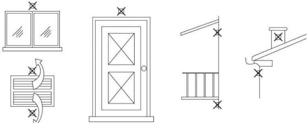
fig. 54- Positioning of external probe not recommended
Accessing the electrical terminal block
The electrical terminal block is located in the back of the boiler. Make the electrical connections as shown in the wiring diagram on fig. 95 and run the cables through the special cable glands.
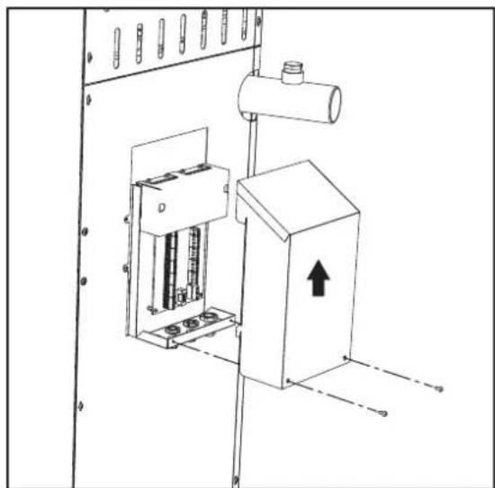
fig. 55-Electrical terminal block

Maximum applicable loads:
- Heating circulating pump: 230Vac 0.8A max, C@98p
3-way valve: 230 Vac, 0.8 A max, G0 for max 1 minute, 0.4 A continuous - Alarm: 230 Vac, 0.8 A max, ∈0.6 φ
For connection in cascade
NOTE: The boiler electronics can manage up to a maximum of 6 modules.
- Connect the modules as shown in fig. 56 (example with 3 modules)
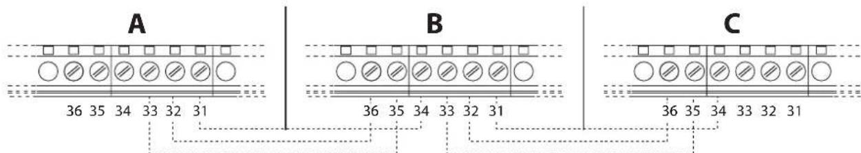
fig. 56- Cascade connection
A 1st Module
C 3rd Module
B 2nd Module
- Carry out all the electrical connections (terminals 1 to 30) on module no.1
- On the remaining modules, connect only the power supply and, if necessary, the contacts relevant to: burner on (300), fault contact (301) and remote reset input (302).
Remove the jumper relevant to: Room Thermostat (72)/Remote Timer Control (139).
- Switch on the power to the entire cascade
-
After the "FH" procedure, check correct operation of the cascade:
-
Module 1: MASTER icon
- Module 2: SLAVE icon
- Module 3: SLAVE icon
If this does not occur, disconnect the power and check the wiring in fig. 56.
Settings
All adjustments must be made on all the modules, whereas Time Programming must be set only on Module 1.
Possible faults
If the electrical connection of a module is disconnected for any reason, module 1 will activate fault F70.
If the electrical connection of a module is disconnected for any reason, the next module will activate fault F71.
2.6 Flue connection
Important
The unit is a B23-type with combustion air drawn from the place of installation, and fume exhaust by means of a fan (operation with flue pressurised), and must be connected to one of the discharge systems indicated below. Before proceeding with installation, check and carefully comply with the local regulations and provisions. Also, comply with the provisions on the positioning of wall and/or roof terminals and the minimum distances from windows, walls, ventilation openings, etc.
Manifold, ducts and flue must be suitably sized, designed and made in compliance with the current regulations. They must be made of suitable materials, i.e. resistant to heat and corrosion, smooth on the inside and tight. In particular, joints must be condensate proof. Also, provide for adequate condensate drainage points, connected to a trap to prevent the condensate formed in the flues from running into the generators.
Connection
To calculate the maximum length of the fume ducts, refer to the maximum available head indicated in table 5.

Before making the flue connection fill the condensate trap with approx. 0.5 liters of water through the flue connections.
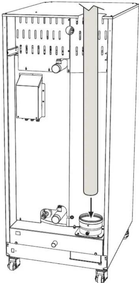
fig. 57-Fume outlet
Table 5- Maximum flue pipe length
| Model “70” Ø 80 | Model “125” Ø 100 | Models “160” “220” Ø 160 | Models “320” “450” Ø 200 | |
| Maximum flue head 200 Pa 200 Pa 200 Pa 200 Pa 200 Pa | ||||
2.7 Condensate drain connection
The boiler has a trap to drain condensate. Proceed as follows for assembly.

ATTENTION: The unit must never be operated with the trap empty!
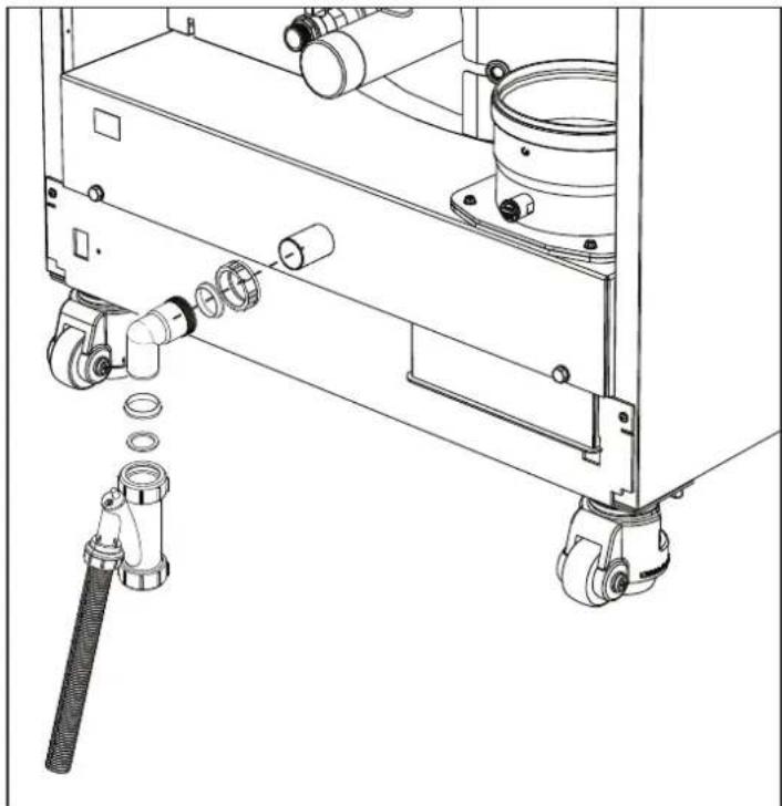
fig. 58- Condensate drain connection
Neutralizer kit
The following condensate neutralizer kits are available on request:
code 051000X0 up to 320kW
code 051002X0 up to 1500 kW
code 051003X0 up to 1500kW (con pompa di rilancio)
Connect these neutralizers directly to the boiler outlet without putting the trap in between. The trap function is carried out by the neutralizer.
3. Service and maintenance
All adjustment, conversion, commissioning and maintenance operations described below must only be carried out by Qualified Personnel (meeting the professional technical requirements of current regulations) such as the personnel of the Local After-Sales Technical Service.
FERROI declines any liability for damage and/or injury caused by unqualified and unauthorized persons tampering with the unit.
3.1 Adjustments
Gas conversion
The unit can run on natural gas or LPG and is factory-set for use with one of these two gases, as clearly shown on the packing and on the data plate. Whenever a different gas to that for which the unit is set has to be used, the special conversion kit will be required, proceeding as follows:
- Disconnect the power supply to the boiler.
- Remove the panels.
- Detach the electrical connections from the gas valve controller.
- Undo the fastening screws "E" and remove the gas valve.
- Replace the gas nozzle "F", positioning it inside the gasket "G". with that contained in the conversion kit. Refit the parts and check tightness.
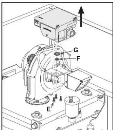
fig. 59- Model OPERA 70
- Modify the parameter for the type of gas as described below.
Reach the screen shown in fig. 63, navigating in the menu and following the path "USER MENU Maintenance Test Mode Gas Type Selection". Press the contextual buttons 1 and 2 to select the type of gas. Confirm with the OK button.
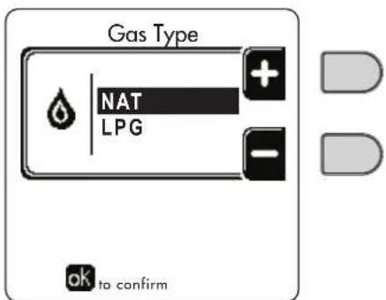
fig. 63 - Gas type selection
- Apply the label, contained in the conversion kit, near the data plate.
- Using a combustion analyzer connected to the boiler fume outlet, make sure the CO _2 content in the fumes, with the boiler operating at max. and min. output, complies with that given in the technical data table for the corresponding type of gas.
TEST mode activation
Reach the screen shown in fig. 64, navigating the following menu path: "USER MENU Maintenance Test Mode Test mode".
The boiler will light, gradually reaching the maximum heating power (Range Rated) set as described in the next section. The display will show the actual heating power and that set.
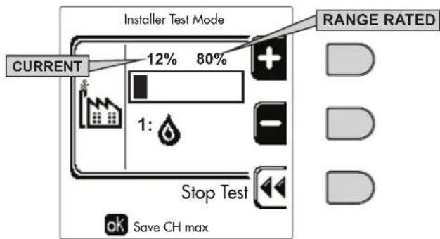
fig. 64 - Test mode (example heating power = 80%)
Press the contextual buttons 1 and 2 to increase the maximum power.
To deactivate the TEST mode, press the contextual button 3.
The TEST mode is automatically disabled in any case after 15 minutes.

After activating test mode, to exit the TEST make sure to deactivate the function, only by pressing the contextual button "Stop Test".
DO NOT TURN OFF THE BOILER ELECTRICALLY DURING THE TEST.
If that happens, when the power is switched on again the system does not recognise deactivation of the TEST, and starts working as though still in TEST mode and not as in a normal heating demand.
Heating Capacity Adjustment (RANGE RATED)

This is a "RANGE RATED" boiler (according to EN 483) and can be adjusted to the system's thermal requirement by setting the maximum heating capacity for operation in heating mode, as follows:
- Put the boiler in TEST mode (see sec. 3.1).
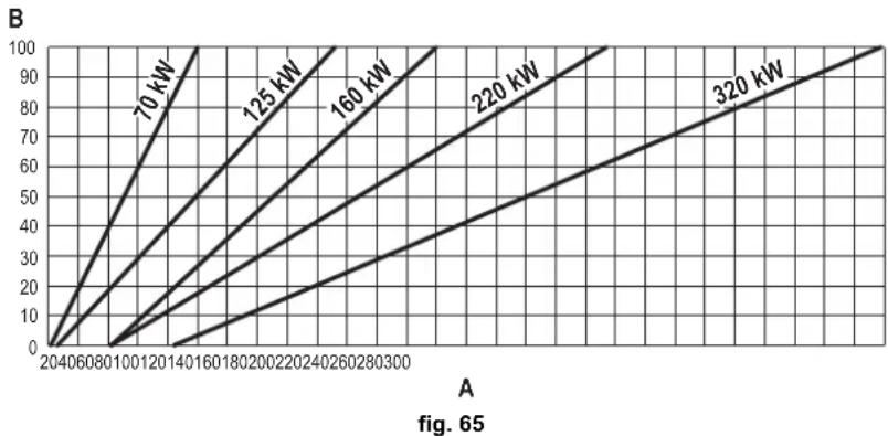
- Press the contextual buttons 1 and 2 to increase or decrease the heating capacity (minimum = 00 - maximum = 100). See the diagram "Heating Capacity Adjustment" (fig. 65).
- By pressing the OK button (detail 6 - fig. 1) the maximum heating capacity will remain that just set. Exit TEST mode (see sec. 3.1).
After setting the desired heating capacity, write the value on the sticker provided and place it on the boiler under the data plate. For subsequent checks and adjustments, refer to the set value.

THE HEATING CAPACITY ADJUSTMENT THUS MADE ENSURES THE EFFICIENCY VALUES DECLARED AT cap. 4.3 "Technical data table"
Heating capacity adjustment diagram
A = kW - B = Electronic Board Parameter
CASCADE TEST mode activation
This function allows all the modules connected in cascade (RANGE RATED) to be activated at the same heating power. From the Master boiler panel (identifiable by the icon 空 ^ 空 ), reach the screen shown in fig. 66, navigating the following menu path: "USER MENU Maintenance Test Mode Test mode".
The modules will light, reaching the maximum heating power (Range Rated) gradually.
The display will show the actual heating power (fig. 66 - example with two modules).
- 5% = Actual heating power
- 1/2 = Modules lit/Modules connected
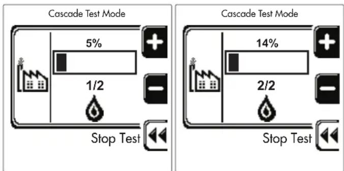
fig. 66 - Cascade TEST mode (example with two modules)
Press the contextual buttons 1 and 2 to increase the maximum power of all modules.
To deactivate the CASCADE TEST mode, press the contextual button 3.
The CASCADE TEST mode is disabled automatically in any case after 15 minutes.

After activating test mode, to exit the TEST make sure to deactivate the function, only by pressing the contextual button "Stop Test".
DO NOT TURN OFF THE BOILER ELECTRICALLY DURING THE TEST.
If that happens, when the power is switched on again the system does not recognise deactivation of the TEST, and starts working as though still in TEST mode and not as in a normal heating demand.
TECHNICAL MENU
ONLY QUALIFIED PERSONNEL CAN ACCESS THE SERVICE MENU AND MODIFY PARAMETERS.
The Technical Menu can only be accessed after entering the code 4 1 8. It is valid for 15 minutes.
Configuration - Parameters Menu
16 parameters are available, indicated by the letter "b", which are not modifiable from Remote Timer Control.
Table 6- Parameters - Configuration
| Parameter | Description Range | 70 125 | 160 220 3 | 20 450 | ||||
| b01 | Gas type selection Natural Gas/LPG | Natural gas Natural gas Natural gas | Natural gas | Natural gas | Natural gas | |||
| b02 | Boiler type selection | 1÷6 = Not used7 = Heating only8 = Combi with storage tank with double pump9 = Combi with storage tank with diverter valve | 7 | 7 | 7 | 7 | 7 | 7 |
| b03 | System water pressure protection selection | 0 = Pressure switch1 = Flow switch 1 sec2 = Flow switch 3 sec3 = Flow switch 5 sec4 = Flow switch 10 sec5 = Pressure transducer | 0 | 0 | 0 | 0 | 0 | 0 |
| b04 | Fan max. frequency in DHW 0-255 Hz | 210 Hz 200 Hz 230 Hz 180 Hz 190 Hz 240 Hz | ||||||
| b05 | Fan max. frequency in heating 0-255 Hz | Hz 210 Hz 200 Hz 230 Hz 180 Hz 190 Hz 240 Hz | ||||||
| b06 | Fan min. frequency in DHW/heating | 0-255 Hz | 50 Hz | 50 Hz | 45 Hz | 45 Hz | 45 Hz | 60 Hz |
| b07 | Fan min. Frequency Offset | 0-255 Hz | 40 Hz | 40 Hz | 40 Hz | 40 Hz | 40 Hz | 60 Hz |
| b08 | Variable output Relay operation selection | 0=Burner lit1=Legionella pump2=Boiler room ventilation3=Motor-operated shutoff valve | 0 | 0 | 0 | 0 | 0 | 0 |
| b09 | Post-Ventilation | 0-120 seconds | 30 | 30 | 30 | 30 | 30 | 30 |
| b10 | Boiler room pre-ventilation | 1-15 minutes | 1 | 1 | 1 | 1 | 1 | 1 |
| b11 | Boiler room post-ventilation | 1-15 minutes | 1 | 1 | 1 | 1 | 1 | 1 |
| b12 | Fume sensor | OFF = Deactivated,ON = Enabled | ON | ON | ON | ON | ON | ON |
| b13 | Not implemented | -- | -- | -- | -- | -- | -- | -- |
| b14 | Fumes Max Temperature | 0-125°C | 110 | 110 | 110 | 110 | 110 | 110 |
| b15 | Fan type selection | -- | -- | -- | -- | -- | -- | -- |
| b16 | Pump antiblock operation time 0-20 seconds | $ |
Notes
- Parameters with more than one description vary their function and/or range in relation to the setting of the parameter given in brackets.
- Parameters with more than one description are reset to the default value if the parameter given in brackets is modified.
Parameters Menu - Transparent Parameters
31 parameters are available, indicated by the letter "P", which are not modifiable from Remote Timer Control.
Table 7- Parameters - Transparent
| Parameter Description Range | 70 125 160 220 320 450 | |||||||
| P01 | Ignition power 0-100% 30 30 50 45 30 40 | |||||||
| P02 | Heating ramp 1-10°C/minute 1 1 1 1 1 1 | |||||||
| P03 | Virtual setpoint min. temperature 20-80°C 20 20 20 20 20 20 | |||||||
| P04 | Heating standby time | 0-10 minutes | 4 4 4 4 4 4 | |||||
| P05 | Heating Post-Circulation | 0-255 minutes | 3 3 3 3 3 3 | |||||
| P06 | Pump operation | 0-3 Operation strategy | 0 0 0 0 0 0 | |||||
| P07 | Modulating pump min. speed | 0-100% 30 30 30 30 30 30 | ||||||
| P08 | Modulating pump start speed | 0-100% 75 75 75 75 75 75 75 | ||||||
| P09 | Modulating pump max. speed | 30-100% | 100 | 100 | 100 | 100 | 100 | 100 |
| P10 | Pump deactivation temperature during Post-Circulation | 0-100°C 35 35 35 35 35 35 35 | ||||||
| P11 | Pump activation hysteresis temperature during Post-Circulation | 0-20°C | 5 | 5 | 5 | 5 | 5 | 5 |
| P12 | Heating user min. setpoint | 10 ÷ 80°C | 20 20 20 20 20 20 20 20 20 20 20 20 20 20 20 20 20 20 20 20 20 20 20 20 20 20 20 20 20 20 20 20 20 20 10°C | |||||
| P13 | Heating user max. setpoint | 20 ÷ 80°C | 80 80 80 80 80 80 80 80 80 80 80 80 80 80 80 80 80 80 80 80 80 80 80 80 80 80 80 80 80 80 80 80 80 80 10°C | |||||
| P14 | Max. output in heating | 0-100% 80 80 80 80 80 80 80 80 80 80 80 80 80 80 80 80 80 80 80 80 80 80 80 80 80 80 80 80 80 80 80 80 80 | 1-10°C/min | 5 | 5 | 5 | 5 | 5 |
| P15 | DHW ramp | 1-10°C/min | 5 | 5 | 5 | 5 | 5 | 5 |
| P16 | DHW standby time | 0-255 seconds | 120 | 120 | 120 | 120 | 120 | 120 |
| P17 | DHW pump Post-Circulation | 0-255 seconds | 30 30 30 30 30 30 30 30 30 30 30 30 30 30 30 30 30 30 30 30 30 30 30 30 30 30 30 30 30 30 30 30 30 30 10°C | |||||
| P18 | With B02 = 7 - Not implemented | -- | -- | -- | -- | -- | -- | -- |
| With B02 = 8 - DHW user min. setpoint | 10° ÷ 40° | 10° | 10° | 10° | 10° | 10° | 10° | |
| With B02 = 9 - DHW user min. setpoint | 10° ÷ 40° | 10° | 10° | 10° | 10° | 10° | 10° | |
| P19 | With B02 = 7 - Not implemented | -- | -- | -- | -- | -- | -- | -- |
| With B02 = 8 - DHW user max. setpoint | 40° ÷ 70° | 65° | 65° | 65° | 65° | 65° | 65° | |
| With B02 = 9 - DHW user max. setpoint | 40° ÷ 70° | 65° | 65° | 65° | 65° | 65° | 65° | |
| P20 | Max. output in DHW | 0-100% | 80% | 80% | 80% | 80% | 80% | 80% |
| P21 | With B02 = 7 - Not implemented | -- | -- | -- | -- | -- | -- | -- |
| With B02 = 8 - Hot water tank hysteresis | 0° ÷ 60° | 2° | 2° | 2° | 2° | 2° | 2° | |
| With B02 = 9 - Hot water tank hysteresis | 0° ÷ 60° | 2° | 2° | 2° | 2° | 2° | 2° | |
| P22 | With B02 = 7 - Not implemented | -- | -- | -- | -- | -- | -- | -- |
| With B02 = 8 - Primary setpoint | 70° ÷ 85° | 80° | 80° | 80° | 80° | 80° | 80° | |
| With B02 = 9 - Primary setpoint | 70° ÷ 85° | 80° | 80° | 80° | 80° | 80° | 80° | |
| P23 | With B02 = 7 - Not implemented | -- | -- | -- | -- | -- | -- | -- |
| With B02 = 8 - Legionella protection | ON - OFF | OFF | OFF | OFF | OFF | OFF | OFF | |
| With B02 = 9 - Legionella protection | ON - OFF | OFF | OFF | OFF | OFF | OFF | OFF | |
| P24 | Fan frequency in standby mode | 0-255 Hz | 0 0 0 0 0 0 0 | |||||
| P25 | Modulating pump adjustment temperature | 0-60°C | 20 20 20 20 20 20 20 20 20 20 20 20 20 20 20 20 20 20 20 20 20 20 20 20 20 20 20 20 20 20 20 20 10°C | 35 35 35 35 35 35 35 35 35 35 35 35 35 35 35 35 35 35 35 35 35 35 35 35 35 35 35 35 35 35 35 35 35 35 10°C | ||||
| P26 | Primary exchanger protection temperature | 0-80°C | 35 35 35 35 35 35 35 35 35 35 35 35 35 35 35 35 35 35 35 35 35 35 35 35 35 35 35 35 35 35 35 35 10°C | 35 35 35 35 35 35 35 35 35 35 35 35 35 35 35 35 35 35 35 35 35 35 35 35 35 35 35 35 35 35 35 30°C | ||||
| P27 | System min. pressure value | -- | -- | -- | -- | -- | -- | |
| P28 | System nominal pressure value | -- | -- | -- | -- | -- | -- | |
| P29 | Exchanger protection intervention | 0=No F43,1-15=1-15°C/second | 0 | 0 | 0 | 0 | 0 | 0 |
| P30 | Heating hysteresis after ignition | 6-30°C | 10 10 10 10 10 10 10 10 10 10 10 10 10 10 10 10 10 10 10 10 10 10 10 10 10 10 10 10 10 10 10 10 10 10 20°C | |||||
| P31 | Timer for heating hysteresis after ignition | 0-180 seconds | 60 | 60 | 60 | 60 | 60 | 60 |
Notes
- Parameters with more than one description vary their function and/or range in relation to the setting of the parameter given in brackets.
- Parameters with more than one description are reset to the default value if the parameter given in brackets is modified.
- The Maximum Heating Power parameter can also be modified in Test Mode.
System Type - Parameters Menu
23 parameters are available, indicated by the letter "P." which are not modifiable from Remote Timer Control.
| Parameter | Description Range | 70 | 125 | 160 | 220 | 320 | 450 | ||
| P.01 | Heating request selection | 0 = Normal heating request1 = Request from remote control with external on-off enabling2 = 0-10V signal request with temperature control with external on-off enabling3 = 0-10V signal request with external on-off enabling4 = Control of 2 climatic curves with remote control-room thermostat and second room thermostat5 = Control of 2 climatic curves with remote control-room thermostat and second room thermostat | 0 | 0 | 0 | 0 | 0 | 0 | 0 |
| P.02 | Cascade sensor selection | 0 = Disabled1 = CH + DHW (Heating + DHW)2 = CH (Heating) | 0 | 0 | 0 | 0 | 0 | 0 | 0 |
| P.03 | N o f u n c t i o n | 0 - 1 0 0 0 0 0 0 | |||||||
| P.04 | 3-way valve time 0 + 255 seconds 0 0 0 0 | 0 0 | |||||||
| P.05 | Activation timer* 0 + 255 minutes 1 1 1 1 | 1 1 | |||||||
| P.06 | Deactivation timer* 0 + 255 minutes 5 5 5 5 | 5 5 | |||||||
| P.07 | Activation power* | 0 ÷ 100% | 70 | 70 | 70 | 70 | 70 | 70 | 70 |
| P.08 | Deactivation power* | 0 ÷ 100% | 25 | 25 | 25 | 25 | 25 | 25 | 25 |
| P.09 | Hydraulic separator function | OFF = Disabled, ON = Enabled | OFF | OFF | OFF | OFF | OFF | OFF | OFF |
| P.10 | System filling function | OFF = Disabled, ON = Enabled | OFF | OFF | OFF | OFF | OFF | OFF | OFF |
| P.11 | 3-way valve selection | 2/3 = 2 or 3 wires2 = 2 wires | 2/3 | 2/3 | 2/3 | 2/3 | 2/3 | 2/3 | 2/3 |
| P.12 | 0-10Vdc Heating OFF voltage (Temperature Control)** | 0.1-10 Vdc | 2.5 | 2.5 | 2.5 | 2.5 | 2.5 | 2.5 | 2.5 |
| P.13 | 0-10Vdc Heating ON voltage (Temperature Control)** | 0.1-10 Vdc | 3.0 | 3.0 | 3.0 | 3.0 | 3.0 | 3.0 | 3.0 |
| P.14 | 0-10Vdc Max. voltage (Temperature Control)** | 0.1-10 Vdc | 10 | 10 | 10 | 10 | 10 | 10 | 10 |
| P.15 | 0-10Vdc Min. temperature (Temperature Control)** | 0 ÷ 100°C | 20 | 20 | 20 | 20 | 20 | 20 | 20 |
| P.16 | 0-10Vdc Max. temperature (Temperature Control)** | 0 ÷ 100°C | 90 | 90 | 90 | 90 | 90 | 90 | 90 |
| P.17 | 0-10Vdc Heating OFF voltage (Power Control)** | 0.1-10 Vdc | 2.5 | 2.5 | 2.5 | 2.5 | 2.5 | 2.5 | 2.5 |
| P.18 | 0-10Vdc Heating ON voltage (Power Control)** | 0.1-10 Vdc | 3.0 | 3.0 | 3.0 | 3.0 | 3.0 | 3.0 | 3.0 |
| P.19 | 0-10Vdc Max. power (Power Control)** | 0.1-10 Vdc | 10 | 10 | 10 | 10 | 10 | 10 | 10 |
| P.20 | 0-10Vdc Min. power (Power Control)** | 0-100% | 0 | 0 | 0 | 0 | 0 | 0 | 0 |
| P.21 | 0-10Vdc Max. power (Power Control)** | 0-100% | 100 | 100 | 100 | 100 | 100 | 100 | 100 |
| P.22 | Enable DHW Slave boiler (Autocascade) | OFF = Disabled, ON = Enabled | OFF | OFF | OFF | OFF | OFF | OFF | OFF |
| P.23 | Continuous comfort Slave boiler (AX5200SQ) | OFF = Disabled, ON = Enabled | OFF | OFF | OFF | OFF | OFF | OFF | OFF |
Notes
-
- These parameters are active only when several systems are connected in cascade.
- ** These parameters are active only when the system operates with input 0-10Vdc.
3.2 Commissioning

Checks to be done at first lighting, and after all maintenance operations that involved disconnection from the systems or work on safety devices or parts of the boiler:
Before lighting the boiler
- Open any on-off valves between the boiler and the systems.
- Check the tightness of the gas system, proceeding with caution and using a soap and water solution to detect any leaks in connections.
- Check correct prefilling of the expansion tank (ref. sec. 4.3).
- Fill the water system and make sure all air contained in the boiler and the system has been vented, by opening the air vent valve on the boiler and any vent valves on the system.
- Fill the condensate trap and check correct connection of the condensate elimination system.
- Make sure there are no water leaks in the system, DHW circuits, connections or boiler.
- Check correct connection of the electrical system and efficiency of the earthing system
- Make sure the gas pressure value for heating is that required.
- Make sure there are no flammable liquids or materials in the immediate vicinity of the boiler

IF THE ABOVE INSTRUCTIONS ARE NOT OBSERVED THERE MAY BE RISK OF SUFFOCATION OR POISONING DUE TO GAS OR FUMES ESCAPING; DANGER OF FIRE OR EXPLOSION. ALSO, THERE MAY BE A RISK OF ELECTRIC SHOCK OR FLOODING THE ROOM.
Checks during operation
- Turn the unit on as described in sec. 1.3.
- Make sure the fuel circuit and water systems are tight.
- Check the efficiency of the flue and air-fume ducts while the boiler is working.
- Check the correct tightness and functionality of the condensate elimination system and trap.
- Make sure the water is circulating properly between the boiler and the systems.
- Make sure the gas valve modulates correctly in the heating and domestic hot water production phases.
- Check proper boiler lighting by doing several tests, turning it on and off with the room thermostat or remote control.
- Using a combustion analyser connected to the boiler fume outlet, check that the CO _2 content in the fumes,with the boiler operating at max. and min. output, corresponds to that given in the technical data table for the corresponding type of gas.
- Make sure the fuel consumption indicated on the meter matches that given in the technical data table on sec. 4.3.
- Check the correct programming of the parameters and carry out any necessary customization (compensation curve, power, temperatures, etc.).
3.3 Maintenance
Periodical inspection
To ensure proper operation of the unit, it is necessary to have an annual inspection carried out by qualified personnel, providing for the following:
- heat exchanger check and cleaning with suitable products if dirty or clogged
- check and possible cleaning of burner (do not use chemical products or wire brushes)

IMPORTANT: after cleaning the burner, be sure to position it by aligning the flange joint weld with the center of the peephole hole (see fig. 67).
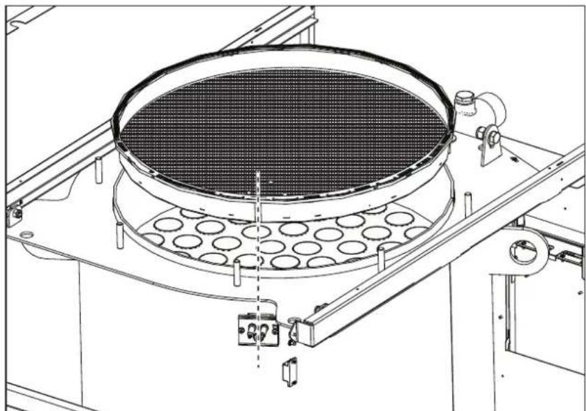
fig. 67 - Alignment of the burner
- check and cleaning of electrodes, which must be free of deposits and properly positioned
- seal and gasket check (burner, sealed chamber, etc.)
- check and cleaning of sludge remover filters and system filters
- check, cleaning and filling of condensate drain traps
- check of wiring, contacts, electrical actuators
- check and cleaning of generator air inlets and boiler room air intakes
- check and cleaning of fume evacuation duct-manifold-flue system.
- expansion tank check and prefilling
- check of correct and stable system water pressure, ensuring conformity with the required working pressure.

The use of automatic filling systems for reinstatement of operating conditions must provide for adequate treatment of the water (ref. *** 'System water characteristics' on page 155 ***)
check of heating system water chemical and physical parameters (ref. *** 'System water characteristics' on page 155 ***)
water and gas system tightness check
- check of correct and stable gas supply pressure to plant (20 mbar for operation with natural gas); any fluctuations or pressure drops below the declared value can create malfunctioning and stops with need for manual resetting.
- burner ignition and control and safety device check (gas valve, flowmeter, thermostats, etc.)
- circulating pump check, freeing when necessary
- fume analysis and check of combustion parameters

The casing, control panel and aesthetic parts of the boiler can be cleaned with a soft damp cloth, possibly soaked in soapy water. All abrasive detergents and solvents should be avoided.
Burner door opening
To access the burner observe the following instructions.
- Remove the cover and front panel (fig. 68).
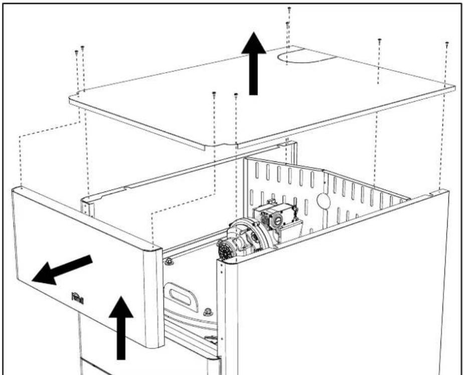
fig. 68
- Remove the rear panels (fig. 69).
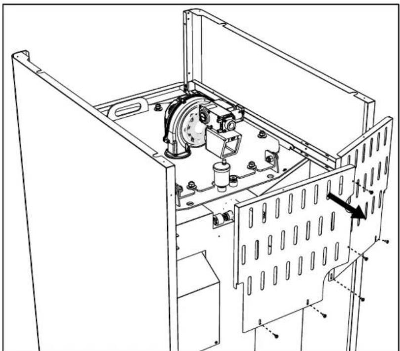
fig. 69
- Remove the nuts and washers (fig. 70).
6 for models OPERA 70 and 125.
8 for models OPERA 160, 220, 320 and 450.
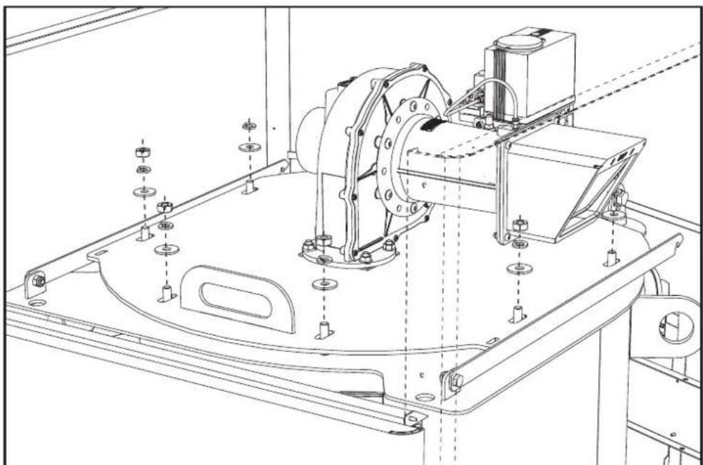
fig. 70
- Open the burner door and block it with the support brackets (fig. 71).
ONE for models OPERA 70 and 125.
TWO for models OPERA 160, 220, 320 and 450.
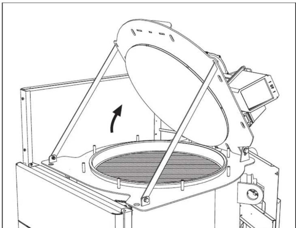
fig. 71
To close it, repeat these operations in reverse order.

Carefully tighten the nuts (fig. 72).
6 for models OPERA 70 and 125.
8 for models OPERA 160, 220, 320 and 450.
When finished check the perfect tightness of the gas circuit.
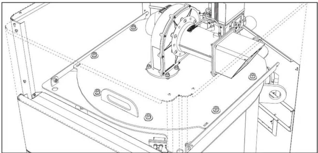
fig. 72
3.4 Troubleshooting
Diagnostics
The boiler is equipped with an advanced self-diagnosis system. In case of a boiler fault, the display lights up indicating the fault code and, in case of cascade connection, the module number.
- There are faults that cause permanent shutdowns which can be reset by pressing the OK button for one second or with the RESET button on the remote timer control (optional) if installed. If the boiler fails to restart after resetting, it is necessary to eliminate the fault first.
- Other faults cause temporary shutdowns which are automatically reset as soon as the value returns within the boiler's normal working range.
Table of faults
Table 8- List of faults
| Fault code | Fault Possible cause | Cure | |
| 01 No burner ignition | No gas | Check the regular gas flow to the boiler and that the air has been eliminated from the pipes | |
| Ignition/detection electrode fault | Check the wiring of the electrode and that it is correctly positioned and free of any deposits | ||
| Faulty gas valve | Check the gas valve and replace it if necessary | ||
| Insufficient gas supply pressure Check the gas supply pressure | |||
| Trap blocked Check the trap and clean it if necessary | |||
| 02 | Flame present signal with burner off | Electrode fault Check the ionization electrode wiring | |
| Card fault Check the card | |||
| Fault code | Fault | Possible cause | Cure |
| 03 | Overtemperature protection intervention | No water circulation in the system Check the circulating pump | |
| Air in the system Vent the system | |||
| 04 | Fume extraction duct safety device intervention | Fault 07 generated 3 times in the last 24 hours See fault 07 | |
| 05 | Fan protection intervention | Fault 15 generated for 1 hour consecutive See fault 15 | |
| 06 | No flame after ignition phase (6 times in 4 minutes) | Ionization electrode fault Check the position of the ionization electrode and replace it if necessary | |
| Flame unstable Check the burner | |||
| Gas valve Offset fault Check the Offset adjustment at minimum power | |||
| air/fume ducts obstructed | Remove the obstruction from the flue, fume extraction ducts, air inlet and terminals | ||
| Trap blocked Check the trap and clean it if necessary | |||
| 07 | High fume temperature | Exchanger dirty Clean the exchanger | |
| Exchanger deteriorated Check the integrity of exchanger | |||
| Sensor does not indicate the correct temperature Check the fume sensor or replace it | |||
| 08 | Heating sensor 1 (flow) overtemperature indication(Viewable only in History Menu) | insufficient system water circulation check water circulation | |
| 09 | Return sensor over-temperature indication(Viewable only in History Menu) | insufficient system water circulation check water circulation | |
| 10 | Heating sensor 1 (flow) fault | Sensor damaged | Check the wiring or replace the sensorWiring shorted |
| Wiring disconnected | |||
| 11 | Return sensor fault | Sensor damaged | Check the wiring or replace the sensorWiring shorted |
| Wiring disconnected | |||
| 12 | DHW sensor fault | Sensor damaged | Check the wiring or replace the sensorWiring shorted |
| Wiring disconnected | |||
| 13 | Fume sensor fault | Sensor damaged | Check the wiring or replace the sensorWiring shorted |
| Wiring disconnected | |||
| 14 | Heating sensor 2 (Safety) fault | Sensor damaged | Check the wiring or replace the sensorWiring shorted |
| Wiring disconnected | |||
| 15 | Fan fault | No 230V power supply | Check the 3-pin connector wiring |
| Tachometric signal interrupted | Check the 5-pin connector wiring | ||
| Fan damaged | Check the fan | ||
| 26 | RESET button on controller on gas valve, fault. | RESET button on controller fitted on gas valve blocked or faulty. | Check the RESET button and replace the controller on the gas valve if necessary. |
| 34 | Supply voltage under 170V | Electric mains trouble Check the electrical system | |
| Fault code | Fault Possible cause | Cure | |
| 35 | Faulty mains frequency | Electric mains trouble Check the electrical system | |
| 37 | Pressure switch contact open | Low system pressure Check the system water pressure | |
| 39 External probe fault | Probe damaged or wiring shorted Check the wiring | or replace the sensor | |
| Probe disconnected after activating the sliding temperature | Reconnect the external probe or disable the sliding temperature | ||
| 41 | No +/-1°C variation of flow sensor | Flow sensor disconnected from pipe | Check the correct positioning and operation of flow sensor |
| 42 | Protection for temperature difference > 21° between flow sensor and safety sensor | Insufficient circulation in boiler Check boiler/system | water circulation |
| Incorrect flow sensor position Check the integrity of sensor | sensor | ||
| 50 | Cascade temperature sensor fault | Sensor damaged | Check the wiring or replace the sensor Wiring sh |
| Wiring disconnected | |||
| 52 | Protection for temperature difference > 18° between flow sensor and safety sensor | Insufficient circulation in boiler | Check boiler/system water circulation |
| Check the integrity of flow and safety sensor | |||
| 61 Controller fault Controller internal error | Check the ground connection and replace the controller if necessary. | ||
| 62 | No communication between controller and gas valve | Controller not connected Connect the controller to the gas valve | |
| Valve damaged Replace the valve | |||
| 63 Controller fault Controller internal error | Check the ground connection and replace the controller if necessary | ||
| 64 | |||
| 65 | |||
| 66 | |||
| 99 | No communication between controller and display | Wiring disconnected | Check the wiring of the 6 wires between controller and display |


4. Technical data and characteristics
Legend of figures cap. 4 "Technical data and characteristics"
7 Gas inlet
10 System flow
16 Fan
32 Heating circulating pump (not supplied)
36 Automatic air vent
44 Gas valve
72 Room thermostat (not supplied)
72b Second room thermostat (not supplied)
81 Ignition electrode
82 Detection electrode
95 3-way valve - 2 wires (not supplied)
A = Heating phase
B = Neutral
98 Switch
114 Water pressure switch
130 DHW circulating pump (not supplied)
138 External probe (not supplied)
139 Remote timer control (not supplied)
154 Condensate drain pipe
155 Hot water tank temperature probe (not supplied)
186 Return sensor
188 Ignition/lonization electrode
191 Fume temperature sensor
220 Ignition card
256 Modulating heating circulating pump signal
275 Heating system drain cock
278 Double sensor (Safety + Heating)
298 Cascade temperature sensor (not supplied)
299 Input 0-10 Vdc
300 Burner lit contact (voltage-free contact)
301 Fault contact (voltage-free contact)
302 Remote reset input (230 Volt)
306 Heating system circulating pump (not supplied)
307 Heating system second circulating pump (not supplied)
321 Low temperature return
346 High temperature return
348 3-way valve - 3 wires (not supplied)
A = Heating phase
B = Neutral
C=DHW phase
357 Faulty contact (230 Vac)
361 Cascade connection of next module
362 Cascade connection of previous module
363 MODBUS communication
4.1 Dimensions, connections and main components
Views for the model 70
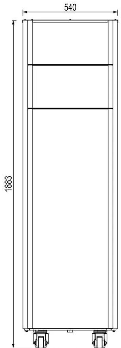
fig. 73- Front
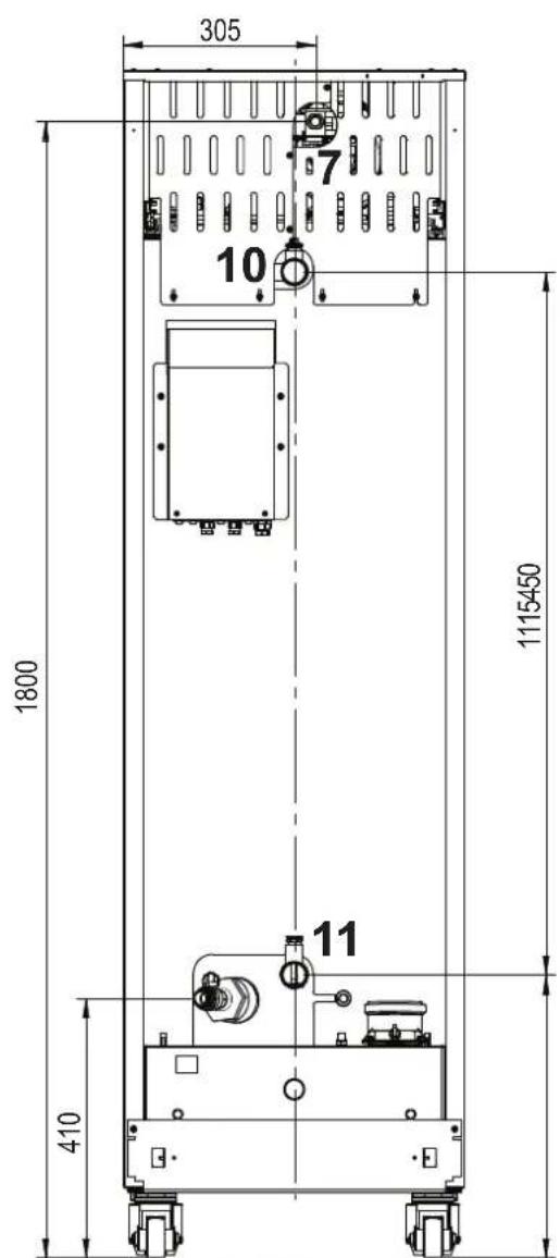
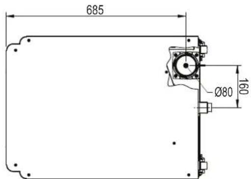
fig. 74- Rear
fig. 75-Top
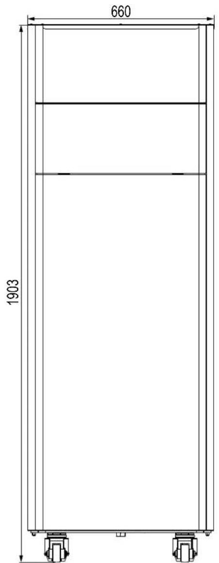
Views for the model 125
fig. 76- front fig. 77- rear
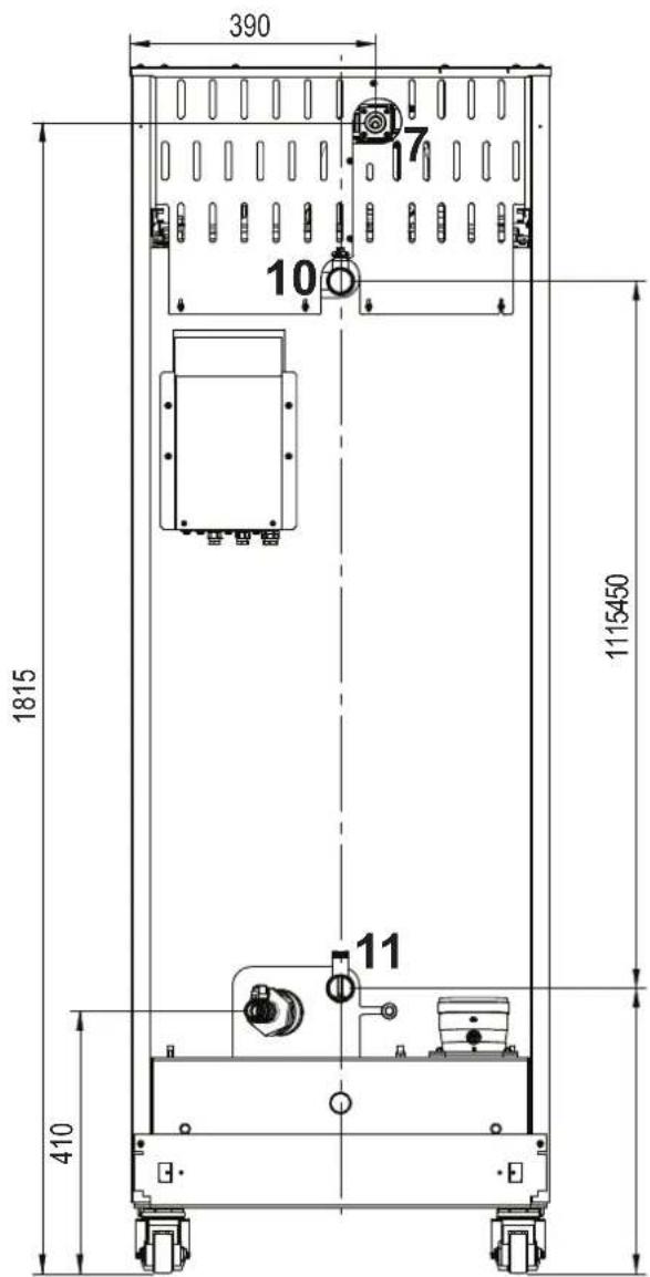
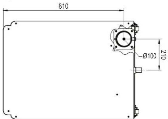
fig. 78- top
Views for the model 160 and 220
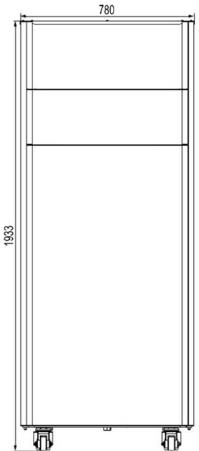
fig. 79- front
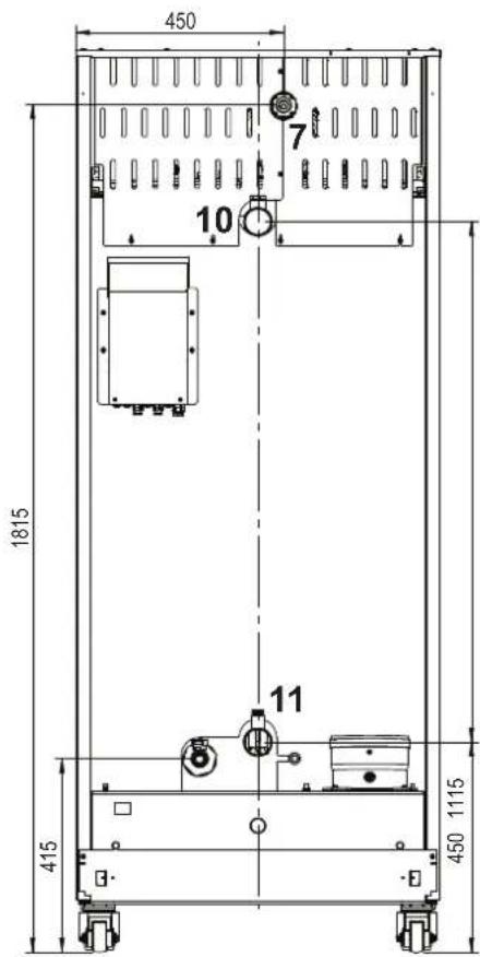
fig. 80- rear 160
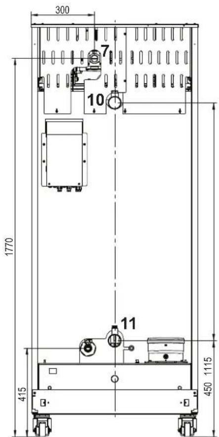
fig. 81- rear 220
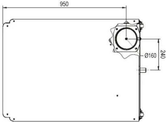
fig. 82-top
Views for the model 320
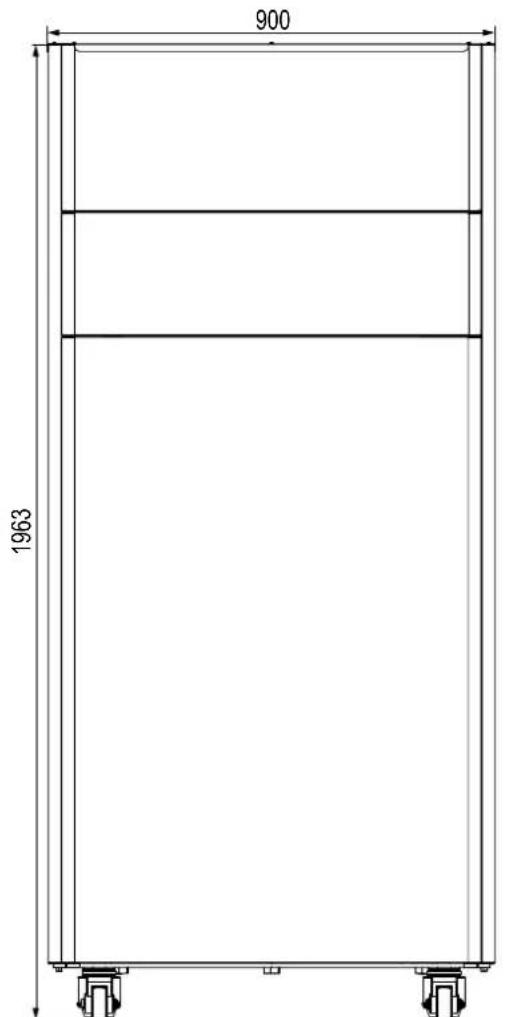
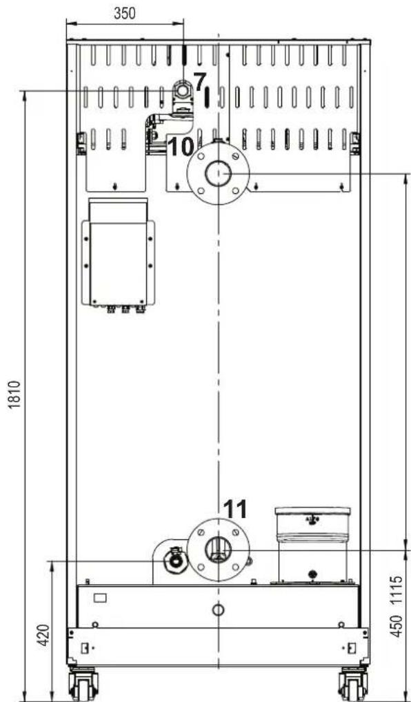
fig. 83- Front view model 320 fig. 84- Rear view model 320
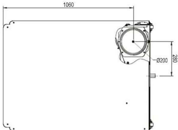
fig. 85-Top view model 320
Views for the model 450
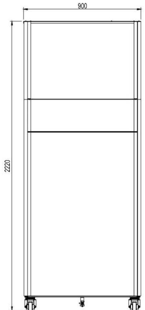
fig. 86- Front view model 450
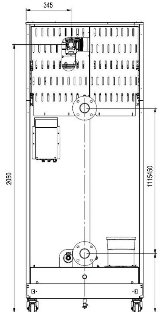
fig. 87- Rear view model 450
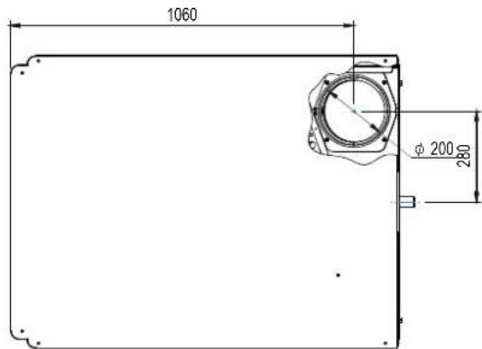
fig. 88-Top view model 450
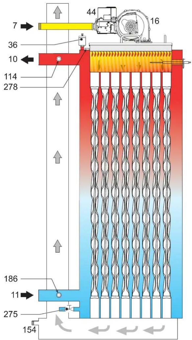
4.2 Hydraulic circuit
fig.89-Hydraulic circuit
4.3 Technical data table
The column on the right gives the abbreviation used on the data plate.
| OPERAS 700RBM4AWA |
| OPERAS 1250RBM7AWA |
| OPERAS 1600RBM8AWA |
| COUNTRIES OF DESTINATION | IT ES RU | |||
| GAS CATEGORY | II2H3B/P (IT) II2H3P (ES) II2H3B/P (RU) | |||
| PRODUCT IDENTIFICATION CODES | 0RBM4AWA | 0RBM7AWA | 0RBM8AWA | |
| Max. heating capacity | kW | 65,5 | 116,0 | 150,0 |
| Min. heating capacity | kW | 14,0 | 23,0 | 41,0 |
| Max. heat output in heating (80/60 °C) | kW | 64,4 | 114,0 | 147,6 |
| Min. heat output in heating (80/60 °C) | kW | 13,7 | 22,5 | 40,2 |
| Max. heat output in heating (50/30 °C) | kW | 70,0 | 123,9 | 160,2 |
| Min. heat output in heating (50/30 °C) | kW | 15,1 | 24,8 | 44,2 |
| Efficiency Pmax (80/60 °C) | % | 98,3 | 98,3 | 98,4 |
| Efficiency Pmin (80/60 °C) | % | 98,0 | 98,0 | 98,0 |
| Efficiency Pmax (50/30 °C) | % | 106,8 | 106,8 | 106,8 |
| Efficiency Pmin (50/30 °C) | % | 107,7 | 107,7 | 107,7 |
| Efficiency 30% | % | 109,7 | 109,7 | 109,5 |
| Flue losses with burner ON (80/60 °C) - Pmax / Pmin | % | 2,30 2,00 | 1,70 1,30 | 1,70 1,30 |
| Shell losses with burner ON (80/60 °C) - Pmax / Pmin | % | 0,04 1,30 | 0,04 1,30 | 0,03 1,30 |
| Flue losses with burner ON (50/30 °C) - Pmax / Pmin | % | 1,10 0,70 | 1,10 0,70 | 1,20 0,60 |
| Shell losses with burner ON (50/30 °C) - Pmax / Pmin | % | 0,04 0,70 | 0,03 0,70 | 0,02 0,70 |
| Flue losses with burner OFF (50K / 20K) | % | 0,03 0,01 | 0,03 0,01 | 0,02 0,01 |
| Shell losses with burner OFF (50K / 20K) | % | 0,26 0,10 | 0,23 0,09 | 0,21 0,08 |
| Fume temperature (80/60 °C) - Pmax / Pmin | °C | 68 60 | 66 60 | 67 61 |
| Fume temperature (50/30 °C) - Pmax / Pmin | °C | 43 33 | 43 32 | 45 31 |
| Temperature of overheating combustion products | °C | 110,0 110,01 | 0,0 | |
| Fume flow rate - Pmax / Pmin | g/s | 29,7 6,7 | 52,7 11,1 | 68,1 19,8 |
| Gas supply pressure G20 | mbar | 20 | 20 | 20 |
| Gas nozzle G20 | ∅ | 6,7 | 9,4 | 9,4 |
| Gas flow rate G20 - Max / min | m3/h | 6,9 1,5 | 12,3 2,4 | 15,9 4,3 |
| CO2 - G20 | % | 9,3±0,3 | 9,3±0,3 | 9,3±0,3 |
| CO - G20 - Max / min | mg/kWh | 28 1 15 | 130 2 | |
| Gas supply pressure G31 | mbar | 37 | 37 | 37 |
| Gas nozzle G31 | ∅ | 5,2 | 7,4 | 7,2 |
| Gas flow rate G31 - Max / min | kg/h | 5,1 1,1 | 9,1 1,8 | 11,7 3,2 |
| CO2 - G31 | % | 10,5±0,3 | 10,5±0,3 | 10,5±0,3 |
| CO - G31 - Max / min | mg/kWh | 23 1 20 | 126 1 | |
| NOx emissions class | - | 6 (< 56 mg/kWh) | ||
| Max. working pressure in heating | bar | 6,0 | 6,0 | 6,0 |
| Min. working pressure in heating | bar | 0,5 | 0,5 | 0,5 |
| Heating adjustment max. temperature | °C | 95 | 95 | 95 |
| Heating water content | liters | 166,0 | 265,0 | 386,0 |
| Heating expansion vessel capacity | liters | / | / | / |
| Heating expansion vessel precharge pressure | bar | / | / | / |
| Protection rating | IP | IPX0D | IPX0D | IPX0D |
| Power supply volta ge | V/Hz | 230V~50HZ | ||
| Electrical power input | W | 105 | 200 | 200 |
| Empty weig ht | kg | 230,0 | 280,0 | 400,0 |
| Type of unit | ||||
These boilers can work correctly with a minimum flow rate of 0 liters/h.
The column on the right gives the abbreviation used on the data plate.
| OPERAS 2200RBMAAWA |
| OPERAS 3200RBMDAWA |
| OPERAS 4500RBMGAWA |
| COUNTRIES OF DESTINATION | IT ES RU | |||
| GAS CATEGORY | II2H3B/P (IT) II2H3P (ES) II2H3B/P (RU) | |||
| PRODUCT IDENTIFICATION CODES | 0RBMAAAW | 0RBMDAWA | 0RBMGAWA | |
| Max. heating capacity | kW | 207,0 | 299,0 | 420,0 |
| Min. heating capacity | kW | 41,0 | 62,0 | 80,0 |
| Max. heat output in heating (80/60 °C) | kW | 203,7 | 294,4 | 412,7 |
| Min. heat output in heating (80/60 °C) | kW | 40,2 | 60,8 | 78,4 |
| Max. heat output in heating (50/30 °C) | kW | 221,1 | 319,3 | 448,6 |
| Min. heat output in heating (50/30 °C) | kW | 44,2 | 66,8 | 86,2 |
| Efficiency Pmax (80/60 °C) | % | 98,4 | 98,4 | 98,3 |
| Efficiency Pmin (80/60 °C) | % | 98,0 | 98,0 | 98,0 |
| Efficiency Pmax (50/30 °C) | % | 106,8 | 106,8 | 106,8 |
| Efficiency Pmin (50/30 °C) | % | 107,7 | 107,7 | 107,7 |
| Efficiency 30% | % | 109,5 | 109,7 | 109,3 |
| Flue losses with burner ON (80/60 °C) - Pmax / Pmin | % | 1,70 1,30 | 2,30 2,10 | 1,70 1,30 |
| Shell losses with burner ON (80/60 °C) - Pmax / Pmin | % | 0,02 1,30 | 0,01 1,30 | 0,01 1,30 |
| Flue losses with burner ON (50/30 °C) - Pmax / Pmin | % | 1,20 0,60 | 1,20 0,60 | 1,20 0,60 |
| Shell losses with burner ON (50/30 °C) - Pmax / Pmin | % | 0,01 0,70 | 0,01 0,70 | 0,01 0,70 |
| Flue losses with burner OFF (50K / 20K) | % | 0,02 0,01 | 0,01 0,01 | 0,01 0,00 |
| Shell losses with burner OFF (50K / 20K) | % | 0,15 0,06 | 0,12 0,05 | 0,11 0,04 |
| Fume temperature (80/60 °C)- Pmax / Pmin | °C | 67 61 | 67 61 | 67 61 |
| Fume temperature (50/30 °C)- Pmax / Pmin | °C | 45 31 | 45 31 | 45 31 |
| Temperature of overheating combustion products | °C | 110,0 110,01 | 0,0 | |
| Fume flow rate - Pmax / Pmin | g/s | 94,0 19,8 | 139,8 30,5 | 196,3 39,3 |
| Gas supply pressure G20 | mbar | 20 | 20 | 20 |
| Gas nozzle G20 | ∅ | 15,5 | 17 | 17 |
| Gas flow rate G20 - Max / min | m3/h | 21,9 4,3 | 31,6 6,6 | 44,4 8,5 |
| CO2 - G20 | % | 9,3±0,3 | 9,0±0,3 | 9,0±0,3 |
| CO - G20 - Max / min | mg/kWh | 40 2 13 | 135 3 | |
| Gas supply pressure G31 | mbar | 37 | 37 | 37 |
| Gas nozzle G31 | ∅ | 11,5 | 12,5 | |
| Gas flow rate G31 - Max / min | kg/h | 16,2 3,2 | 23,4 4,9 | 32,9 6,3 |
| CO2 - G31 | % | 10,5±0,3 | 10,5±0,3 | 10,5±0,3 |
| CO - G31 - Max / min | mg/kWh | 52 2 43 | 236 3 | |
| NOx emissions class | - | 6 (< 56 mg/kWh) | ||
| Max. working pressure in heating | bar | 6,0 | 6,0 | 6,0 |
| Min. working pressure in heating | bar | 0,5 | 0,5 | 0,5 |
| Heating adjustment max. temperature | °C | 95 | 95 | 95 |
| Heating water content | liters | 386,0 | 530,0 | 561,0 |
| Heating expansion vessel capacity | liters | / | / | / |
| Heating expansion vessel precharge pressure | bar | / | / | / |
| Protection rating | IP | IPX0D | IPX0D | IPX0D |
| Power supply volta ge | V/Hz | 230V~50HZ | ||
| Electrical power input | W | 260 | 330 | 800 |
| Empty weig ht | kg | 400,0 | 500,0 | 550,0 |
| Type of unit | B23 | |||
These boilers can work correctly with a minimum flow rate of 0 liters/h.
4.4 ErP tables
ErP product fiche
MODEL: OPERA 70 (ORBM4AWA)
MODEL: OPERA 125 (ORBM7AWA)
MODEL: OPERA 160 (ORBM8AWA)
| ORBM4AWA |
| ORBM7AWA |
| ORBM8AWA |
| TRADEMARK: FERROLI | |||||
| Condensing boiler | YES | YES | YES | ||
| Low-temperature boiler (**) | YES | YES | YES | ||
| B1 Boiler | NO | NO | NO | ||
| Combination heater | NO | NO | NO | ||
| Cogeneration space heater | NO | NO | NO | ||
| Item | SYMBOL | UNIT | VALUE | ||
| Seasonal space heating energy efficiency class (from A+++ to D) | A | A | A | ||
| Rated heat output | Pn | kW | 64 | 114 | 148 |
| Seasonal space heating energy efficiency | ηs | % | 94 | 94 | 94 |
| Useful heat output | |||||
| Useful heat output at rated heat output and high-temperature regime (*) | P4 | kW | 64,4 | 114,0 | 147,6 |
| Useful heat output at 30% of rated heat output and low-temperature regime (**) | P1 | kW | 13,1 | 24,2 | 44,5 |
| Useful efficiency | |||||
| Useful heat output at rated heat output and high-temperature regime (*) | η4 | % | 88,5 | 88,5 | 88,6 |
| Useful heat output at 30% of rated heat output and low-temperature regime (**) | η1 | % | 98,7 | 98,8 | 98,6 |
| Auxiliary electricity consumption | |||||
| At full load | elmax | kW | 0,105 | 0,200 | 0,250 |
| At part load | elmin | kW | 0,019 | 0,025 | 0,035 |
| In standby mode | PSB | kW | 0,003 | 0,003 | 0,003 |
| Other items | |||||
| Standby heat loss | Pstby | kW | 0,190 | 0,300 | 0,350 |
| Ignition burner power consumption | Pign | kW | 0,000 | 0,000 | 0,000 |
| Annual energy consumption | QHE | GJ | 120 | 210 | 290 |
| Sound power level | LWA | dB | 58 | 62 | 68 |
| Emissions of nitrogen oxides | NOx | mg/kWh | 18 | 17 | 22 |
() High-temperature regime means 60^ return temperature at heater inlet and 80^ feed temperature at heater outlet.
(^*) Low temperature means for condensing boilers 30^ , for low-temperature boilers 37^ and for other heaters 50^ return temperature (at heater inlet).
ErP product fiche
MODEL: OPERA 220 (ORBMAAWA)
MODEL: OPERA 320 (ORBMDAWA)
MODEL: OPERA 450 (ORBMGAWA)
ORBMAAWA
ORBMDAWA
ORBMGAWA
| TRADEMARK: FERROLI | |||||
| Condensing boiler | YES | YES | YES | ||
| Low-temperature boiler (**) | YES | YES | YES | ||
| B1 Boiler | NO | NO | NO | ||
| Combination heater | NO | NO | NO | ||
| Cogeneration space heater | NO | NO | NO | ||
| Item | SYMBOL | UNIT | VALUE | ||
| Rated heat output | Pn | kW | 204 | 294 | 413 |
| Seasonal space heating energy efficiency | ηs | % | 94 | 94 | 93 |
| Useful heat output | |||||
| Useful heat output at rated heat output and high-temperature regime (*) | P4 | kW | 203,7 | 294,4 | 412,7 |
| Useful heat output at 30% of rated heat output and low-temperature regime (**) | P1 | kW | 41,6 | 60,6 | 81,6 |
| Useful efficiency | |||||
| Useful heat output at rated heat output and high-temperature regime (*) | η4 | % | 88,6 | 88,7 | 88,5 |
| Useful heat output at 30% of rated heat output and low-temperature regime (**) | η1 | % | 98,6 | 98,8 | 98,4 |
| Auxiliary electricity consumption | |||||
| At full load | elmax | kW | 0,260 | 0,330 | 0,800 |
| At part load | elmin | kW | 0,037 | 0,043 | 0,200 |
| In standby mode | PSB | kW | 0,003 | 0,003 | 0,003 |
| Other items | |||||
| Standby heat loss | Pstby | kW | 0,350 | 0,400 | 0,500 |
| Ignition burner power consumption | Pign | kW | 0,000 | 0,000 | 0,000 |
| Annual energy consumption | QHE | GJ | 375 | 544 | 754 |
| Sound power level | LWA | dB | 72 | 76 | 77 |
| Emissions of nitrogen oxides | NOx | mg/kWh | 22 | 20 | 33 |
(^) High-temperature regime means 60^ return temperature at heater inlet and 80^ feed temperature at heater outlet.
(^*) Low temperature means for condensing boilers 30^ , for low-temperature boilers 37^ and for other heaters 50^ return temperature (at heater inlet).
4.5 Diagrams

Pressure loss
A
fig. 90 - Pressure loss diagram models 70 - 125
A
fig. 91 - Pressure loss diagram models 220, 320 and 450
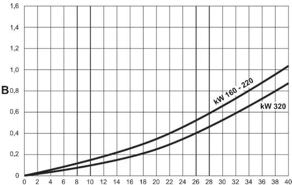
A Flow rate - m 3/h B m H
4.6 Wiring diagrams
ATTENTION: Remove the jumper on the terminal block before connecting the room thermostat or remote timer control.
ATTENTION: To connect the 3-way valve (terminals 13 - 14 - 15), refer to the diagrams of fig. 92 and fig. 93.
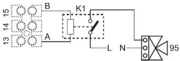
fig. 92- Connection of the 3-way valve with 2 wires
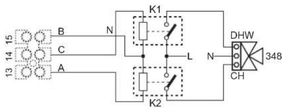
fig. 93- Connection of the 3-way valve with 3 wires
ATTENTION: In case of instability in the reading of the 0-10V signal by the electronic controller, it is advisable to connect the signal reference to ground, and insert a 10K resistor in parallel, as per fig. 94.
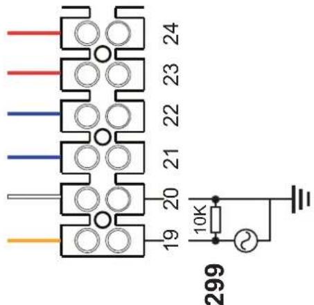
fig. 94-
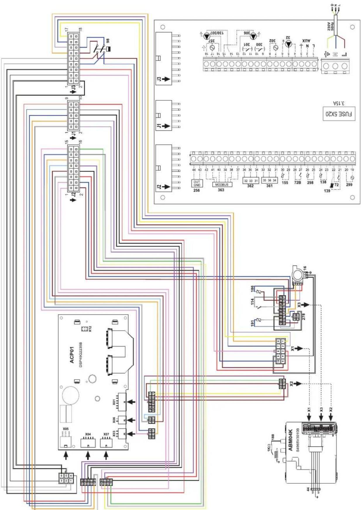
fig. 95-Wiring diagram OPERA 70
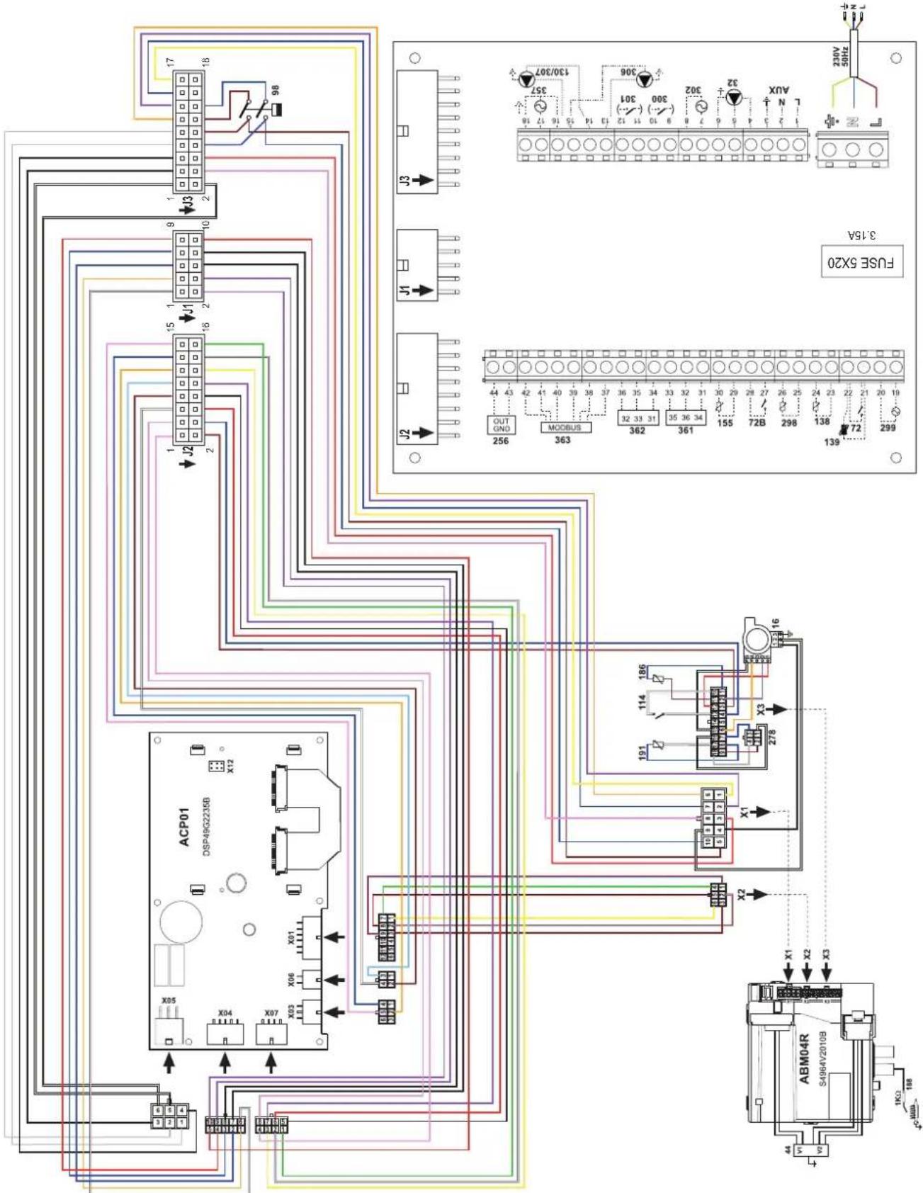
fig. 96-Wiring diagram OPERA 125 and 160
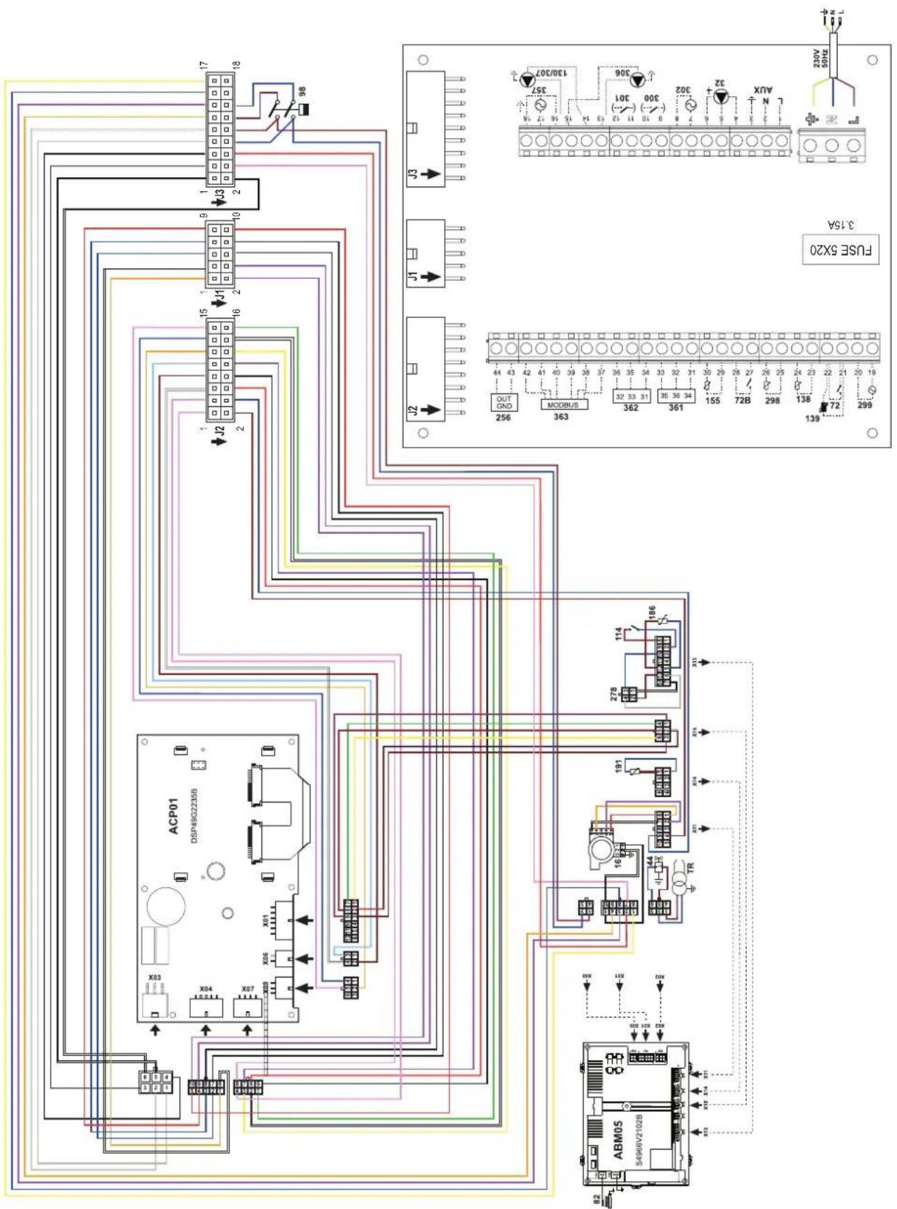
fig. 97-Wiring diagram OPERA 220/320 and OPERA 450

Date Intervention Service
Charges maximum applicable :
YnakoBOUHbIeMaTePuaJIbIyRAJIOTCAHCTOHNKOMNOTEHuaJIbHOI ONaCHOCTN He doJXhbl 6bTb OCTaBHeHb IMcTeA,doCTynHbIX DeTAM.
He p3apeuaTcN cnoNb3OBAHn earperta NmAMn (B TOM YNCNE, DeTbMn) COrpaHnueHBnMn FIn3NueCKMN, CEHCOPbIMn NmYMTCBEHBMn BO3MOXHOCTMn NmIaMn 63 HApJNeAcaJero ObnTa M 3HaHmN, eCNI ON He HAcOJaTc PoD HEnpepbHBbIMn HAdzOpom nnpOnHCTpyKtIpObaHbH AcHepTpabIN 6e3OnaChoro cNoNb3OBAHn aerperta.
-
PnBHeHbIe B HactoTsepykoBOrCTBe N3obpaKeHHa DaOT ynpOuEHHoe npedctBaHene H3dennKToTopoe MoKET HcVUeCTBHeHO OTJNATCbR OT ITOBOrN3dNN
-
YK3AHN NO YTNIN3AUIN OOBYOBAHN
YTNIN3aunioOBOpOBAHnIOnJXHaPpON3BOiNTbCBA CneuAnIn3npoBaHHbIX npEepnpiTHnx CoNACHOeCTBMy 3aKOHDAteJIbCTBy.
- YKA3AHNII NO XPAHEHIO OBOPYOBAHIN
IЯ obcepeHn npabunbHxycNoBx xpaHnry, cTporO pnpdeKHBaTcRyKa3AHm B pyKOBOCTBeN OKcnIyTaunn MapkPOBKe HaYNAKOBe.
06OpdyoBaHne OJnKHO xpaHHTbc B 3aKpblOM n cyXOM NOMEeHHB, BOTCYTCTBN TOKOnPOBOJaIe NbIMnN PnOBaX XmNUeCKN AKTNBHX BeueCtB, PA3pyuAuaOuINx I3OJIauIO TOKONPOBOID. CpOK XpAHeHMa HE ONJeHN ppeBbIaTaB 24 MecHa. No INCTeHHN 24 MeCAeB Heo6xOHaMa IPOBepKa ZENOCHTO6OpDyOBaHH.
PECYPCPA60TbIINCPOKCNJXkbbl
Cpok cnky6bl 3aBcIMOTOyCNBnKcNpyataun, YCTAHOBKN TEXNHUECKORO OCBNYKBHANH.
yctahOBka 06OpOBOAHnI DOnXHa npOn3BOuNTbCBA COOTBcTCTBn C DeNCTByUHm 3aKOHoTaTeNbCTBOM, a HsHaUNBaIOUncE CaTeAun DoONXhbl 6bItb CBOeBPemHo 3AmHeHb.
PeeHHe O npEpaueHHN EKcNpyatauH, cncaHHN yTNn3aunn pnnHMaet BnadeNe HcOAnI 3 aKaHTNUeCKORo COCTOHNbOBPOyDabAHN 3aTpAT Ha peMOHT.
Cpok cnjxkb1-10net
3abOndKa Ta6nHka HaxoNTca Ha 3aDHe CToPoHe KOTna.
1 INcIpyKuI no 3KcnIyatauI 275
1.1 PpeinocnoBne 275
1.2 Panaelb ynpablenna 275
1.3 BkJIIOueHne n BbIKJIIOueHne 279
1.4 PeryunpoBkn 280
2 YcTaHOBka 288
2.1 Yka3aHna o6Iero xapaKTepa 288
2.2 MecTo yCTaHOBKn 288
2.3IindpaBnueckne noKluueHna 288
2.4Γa3OBbIe coeHHeHn 306
2.5 306
2.6 PoioknoueHne K DbIMoxoam 309
2.7 POncoeHHeHne Tpy6bl nIa cInBa KOHeHcata 310
3UxOndTexHnueckoeobcnyKuBaHne 311
3.1 PeruginopBkn 311
3.2BbD B 3KcPnyatauio 317
3.3TexHnueckoe 6cbnyKuBaHne 318
3.4 YcTpaHHe HncnpaBHOtei 321
4XapakTepeNCTnK INTexHnueckne DaHHbIe 324
4.1 Pa3mepbl, noKJIuOHeHn u OCHOBHbIe KOMNoHeHTbl 325
4.2 Tnpabnueckn KOHTyp 330
4.3 Ta6nua texnuecknx daHHbIX 331
4.4 Nnarpammbi 333
4.5 334
1. Иструкции по зацinn
1.1 Праздюве
Ybaxaembl nokynatene!
BlaRapm Bac 3a To, yTo Bb Bb6pnnr OPERA HAnOBHbKOTEN FERROLI, mHeoCn camHyO COBpeMeHHyO KOHCTpyKuio, BblnoHNHeHbNo nepeDobMb TExHOLOrmaN oTINNAUOncra BbICOKo HaedXHOCTbIO KaueCTBOM n3roTOBneHn. Ipocim Bac BHMaTeJbHO npOHtTaHACToaee pyKOBOCTBO, noCKoNBky B HeM cOepkataBaxhHe yka3AHn NO 6e30NaCHOCTn yctahOBKn, EKNJIyataun INTexNHueckomy ObcyKBaHnArperata.
OPERAT - 3TO BBICOKO3ΦEKTNBHBI KOHNHeHCauNoHHB TePMoreHepaTOp C npHyDnTeNbHbIM CmEWeHem IINr CNTEM OToJIeHnRA,pa6oTaIOuHn Ha npnpoHOM nN cKInKeHHom HepTcHOM r3e,OTnNuOuNc Hn3Km yPoBHeM Bbl6pocOB m ChabKeHHB MnkponpoecccopHO CNTEm OynpaBHeHra.
Kopnyc KOTNa COCTOHTN 3aNaTeHTOBaHHORo CNIPAbHOro TENIIO6MeHHNka N3 HEPXABeIOUe CTaN IN CTAJIbHO rOpEnKc npHyDITbHbIM CMeunBaHEm, OCHaSeHHoJ 3NeKTPoHHbIM PO3KINOM C NOHN3aUNOHONC uCTeMOI KOHTPOJ nIaMeHn, BEHTINrTOpOM C perylnpyEMo CKOPoCTbIO IN MOyUInpyUOuIM Ra3OBbIM KIIaHaOM. OPERA IpeDCTabIeT c60BtENIOREhePApOp, IpeDaHa3NaHeHHbI dIpaPbToI OTdEhBO H IN B KAcKaADHom IOKnIOUeHHN.
FERROI npedocabniet no 3anpocy BcIO rnpoTeXnueckyo apMaTyP u DbIMOBBe KONKeKTopbl nla NODcoEHNHeHn2nn 3 arperatobno KaKaadno CxemeB KOHpyaunoxOT 70 + 70KB Do 450 + 450 + 450KB
KoHTeKCTHbIe KnaBnWm
KohtektBHe KnaBn (no3.1,2,3-pnc.1) BbIeJIeHbI cepbIM cBTOM nOTcyTcBnEM ceprrpaHnn, OHN MOry I npNopeTaB pa3HOe 3aBnMocTN OT bIbpaHHoro MeHIO. BaxHo cneOBaTb yka3AHm, KOtOpbe BbIOBaTc H aDnCnIee (IKOH N TEKTb). HanpImep, B pnc.1 C NOMOsbIO KOHTekCTHO Knabn 2 (no3.2-pnc.1) MOxHO NOyHTb DOctyn K INHΦopMaUMn o6 arperate: TempepatypbIM 3HaueHnM, NOyehHbIM OT daTuNKOB, pa6oye MoUHOCTHn T.D.
Ondho3HaHbIe KnaBn
OndnHaHbIe KnaBnN (no3.8,9,10-pnc.1) Bcerda BblonHryOT Ody H ty Jxé FyHKnIO.
KnaBnHn HnBaun/MehIO
KnaBnHabraa/MeHIO (no3.5,6,7,11,12,13-pnc.1) cnykAT nra HabraaM MeJy pa3bIM MeHO Ha naHenn ynpabHeHIA.
CtpyKtypa MeHIO
B rnaBHOM 3kpaHHOM OKHe (Home) HaxMITE Ha KnaBnIy «rnaBHorO MeHIO» (no3.12 - pnc.1).
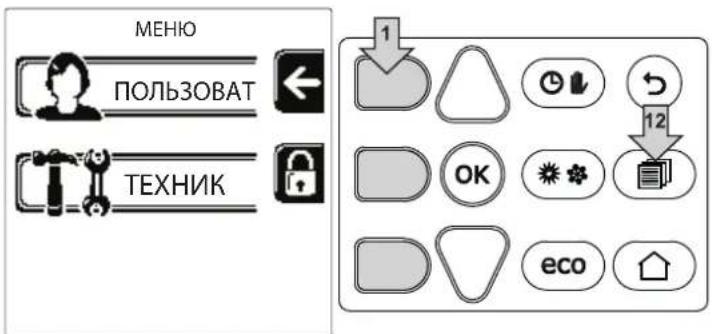
pnc.2
BoiHTe B MeHIO «IOnb3OBeTbI», HAKAB KOHTeKCTHyO KNaBmUy 1 (no3. 1 - pnc. 2). 3aTeM nCNoJIb3yTe KnaBmU N «HaBnraUIM NO MeHIO DnI DoCTyna K pa3NnHbIM ypOBHM, ONncaHHbIM B cneDyIoSe TaBnue.
HdkaunBaBpepa6tkoTna
PexmmOTOnnneHn
Ha 3anpoc Ha OToPnIeHne (ReHepuPyemb KOMHaTHbIM TepMoCTaTOM IIN NytbTom Dc TaImePOM INN CnHAnOM 0-10 B noct. ToKa yka3bIaBET BKIOUChEHe UnpkyIaIIOHOrO HAcOca N HAIIuue ropryero Bo3dyxa HAD paIaNATOpM (PNC. 3).
KoHnpyaunr «TOnbko OToPnneHne/DbouHOu nkpkynaonHHbI Haoc
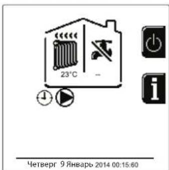
pnc.3
KoHpIpyaIgA «UnpkyIpaHbI Hacoc n 3-xOdoBoI Knaan
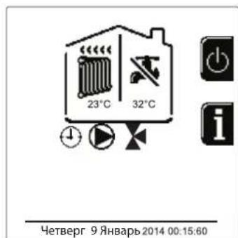
pnc.4
ΓBC (npn HauuBHeHero 6oJIepa)
Ha 3anpoc Ha HarpeB KOtTna yKa3bIbaeA kTmbaunr 3NaK aBnDe KaPnN nOd KpaHOM (PNC.5 n PNC.6).
KoHpyaunrA《DBoHnOuPKyIaUNHOHbHbHaoc》
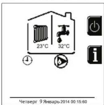
pnc.5
KoHpypaunr «UnpkynnoHHb Hacoc n 3-xoOBOI Klaanah
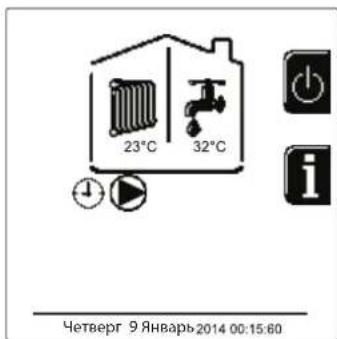
pnc.6
UcknoucheHne 6oJIepa (peXmEconomy)
Iolb30BaTeB NMeET BO3MOXHOCTb NCKHIOUaTb CnCTeMy HArpeBa/NoDcpeKAnHr Tempeatypb BoDb B 6oJInepe. B 3TOM Cnyuae KOTnom He BbipAbaBaETcB Oda Dnra TBC. Koten MoKet 6b1b OTKIOUeH NIOB3OBAteNem (peKIM ECO) HaxaTneM KHONK Eco/Comfort (no3.10 - pnc.1). B peKIMe ECO Ha nCnIee NoRbIaTcR cIMBOI @To6bl akTNBupoBaTb peKIM COMFORT, ChOBa HxKmTe KHOINy Eco/Comfort (no3.10 - pnc.1).
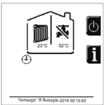
pnc. 7- Economy (3KoHOMn)
HΦopmaua
B rnaHOM 3KpaHOM OKHe (Home) HauKMITE Ha KOHTeKCTHyo KnaBnUy 2 (no3. 2 - pnc. 1). BcneJ 3a 3TmC nOmoIbHO KnaBnW "HaBraun B MeHIO" OTo6pa3nte CneDyUOuie 3HaueHHN:
EcnH He BbIbpaH Hn OINH n3 DByX BblweonncanHbIX BapnaHTOB, DeNCTByTe CNeDyHOUM 6pa3OM.
B TeueHne nocJeIyoUx 300 ckyHn Ha Iucnnee 6ydet BbICBeuBaTbcra CmBOn FH, o6o3naOuuiu nn kn cnycKa BO3dyxa H3 cIcTeMbI OTOpJIeHnA.
Ha nucnnee oTo6paKaetc TaKke BepcnBCTpoeHHoro IIO nnat.
- OtkpoTe ra3OBbI BeHTnIb, yCTaHOBJIeHHbI nepei KOITJOM
Iocne Hcye3HOBeHnHaADnnc FH KOTe rTOB KaBTOMaTHueCKo pa6OteKaXdbpa3 npN NOCTyPHeHn 3aIPoca Ha KOMHaTHbI TepMOCTaT.
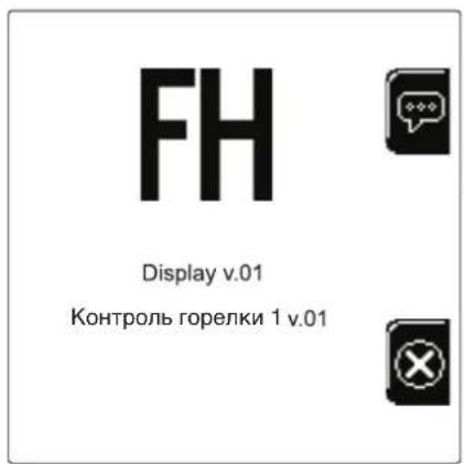
pnc.8-BknooyenneKoTna

Hactpoikn
HactpoKa KOHTpACTHOCTN
TtO6bl HAcTpOnTB KOHTpactHOCTb DnCnIe, Heo6xOIMHO HaxaTb ODHOBpeMeHHo HA KOHTekCTHyIO KnaBnUy 2 nKnaBnUy OK. BcneJ 3a 3TN M HaxmTe Ha KnaBnUy No3.5 B pnc.1, TtO6bl YcNITb KOHTpactHOCTb, INHn HA KnaBnUy No3.7 B pnc.1, TtO6bl ocNaBnTb ee.
HactpoKa DaTbI IN BpeMeHN
BoiDnTe B 3KpaHHe OKHO, nokaahHHe Ha pnc.9, cneDyra no MapuTy "MEHIO NJIb3OBATEJRA "HacTpoiKn
《HactpoKa DaTb》,NcnoB3yIe KhONKn HABRauu 5 n7, YTO6bl Bb6paTb 3HaueHHe N N3MeHnTb erO c NOMoUbHO KOHTeKCTbIX Knabu1 u2. NodTBepDnte C NOMoubHO KHONK OK.
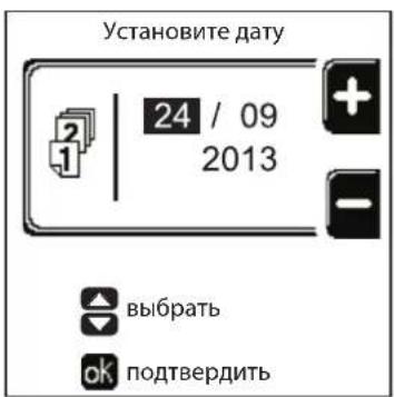
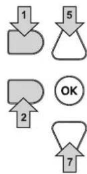
Pnc.9-HacTpoKa DaTbI
BoiDnTe B 3KpaHHe OKnO, NOKa3aHHe Ha pnc.10, CneDyra no MapuTy "MEHIO NOIb3OBATEJI "HAcTpoKn" "HAcTpoKa BpemeH" NcNoB3yte KHOKNi HABrAciuN 5n7, YTO6bl Bb6paTb 3HaueHne NImMeHntb eroc nOMoUbHO KOHTeKTbIX KNaBn1 n2. NoDTBePdnte c nOMoUbHO KHOKN OK.
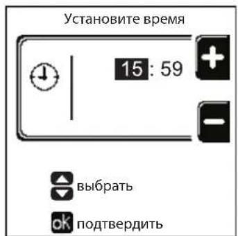
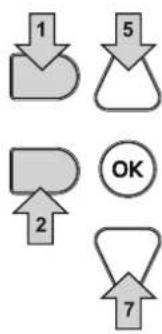
pnc.10-HacTpoKa rpaФиKa pa6OtbI
BbIKHoueHne KOtna
B rnaBHOM 3KpaHnHOM OKHe (Home) HaxMnte Ha KOHTeKCTHyIO KnaBnUy n noTBePdNTe C nOmoIbHO KHONK OK.
Korda KOTeB BbIKIOueH,Ha 3JIeKtpoHHy0 nnatY npoDnKaet nOdaBaTbc 3JIeKtpuYeCKoe PHTaHne.
B 3TOM clyuae He npocxodn HarpeB BOdy dny FBC (npn HauHH BHeHrero 6oJepa) n OTOnJIeHn OcTaETcA kTINBHON IpOTnBOO6JeDeHntEnbHa CNTema.
Ytobb CHOBA BKNIOHTb KOTeH, HAXMnTe NOBTOpHO KOHTeKCTHYO KnaBmUy
Tenepb KOTen roTOB K ABToMaTHueCKOMy BKNIOUeHnO npK kaxDom 3abope ropay BoDbI (npn HAnuNn BHeuHero Boiepa) npi npn NOCTyJIeHm N KOMaHdbI OT KOMHaTHoro TepMoCTata
YTO6bl NIOHOCTbIO OTKIOCHNTb np6Op OT 3NEKTPocETn, HAKMITE Ha KHONKY no3.14 pnc.1.
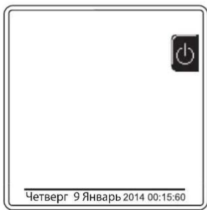


pnc.11-BbIKHIOueHHeKOTna
IpnOTKnIOUeHnKOTnOCTeMbI 3JIeKTPoNITAHn N/INrA3OBoMmRNCtpaHn npOTNbBOO6NeDeHnTeBHa nCtema He pa6oTaET. Bo Bpemr DnITeBHoro HncNoJb3OBaHnKOTnB 3IMHn nepNO, BO n36exKaHne yuep6a OT BO3MOxHOro 3aMeP3aHnpeKOMeHdyETcraNTb BCIO BDOy N3 KOTn, KaK n3 KOHTypa OToPHeHn, TaK nN3 KOHTypa TBC; INn JCe CnITb ToNbKO BDOy N3 KOHTypa TBC n Do6aBnTb aHTnΦpN3 B CNTeMy OToPHeHn B COOTBETCTBn C yka3aHnMa, npNBedeHHbIMn Bsez.2.3.
1.4 PergunpoBkn
IpeeknoueHne pexHmOB "JTo"/"3MaMa"
HaxmTe KhoNky (no3.9-pnc.1)Ha 1 cekyHny.
Ha Dnncnnee noBnIeTc nmbo "IeTo". FyHKuH OtonJIeHnO tKIOUaETcA, a npOn3BOcTBO BODbl 6bIbTOBO nOTpe6IeHn npn Heo6xOUMocTn octaetc AKTINBHbIM (C DonJHInTeNbHbIM BHeuHM BoIIepOM). Octaetc AKTINBHO npOtNUO6IeHnTeNbHra CnCTema.
YTO6bI BIKHOHTB NtTHN peKIM, HAKMNTe KNONKy eHepa3. (no3.9-pnc.1) Ha 1 cekyHdy.
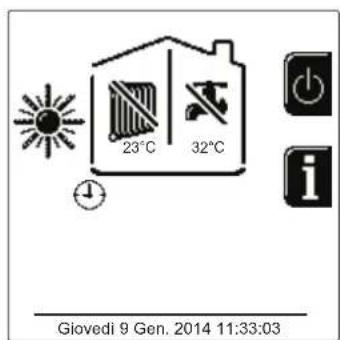
pnc.12-LeTHn peKIM
Perynnpobka TempepaTpybl BObl B CnCTMe OTonneHna
BoiNTe B MeHIO "Temnepatypa perynpOBKn" nIy
N3MeHeHnra TemnepaTypb OT MHNMaIbHOrO 3HaYeHnra
Tmin Do MaKcMmaIbHoro TMax. NpDTBepnte C nOMOuBIO
KHONIK OK.

KoteI npOaetcC HeakTNBHBIM rpaqNKOM pa60TbI.
CneDobateIbHO, B Cnyae 3anpoca 3TO 3HaueHHe NocnykNT yCTaBkoJ.
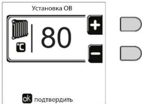
pnc.13
ChnHexHe TempepaTpybl OToIeHn
BoiDte B MeHIO "ToHxHeHne TempeatypbI perynpoBKn"ДЯИЗMeHEnHЯ TempeaTpybI OT MHNIMyM 0^ doMaKcMym 50^ 。ПодТВердeTe C nOMOuь KHOJKN OK.

3TOT npametnp nCnoB3yETcra, TOnbko ecnBkNoyeHo npOrpaMMnPOBaHne rpaФnka pa60tbo no yacam. Cm. "PpOrpaMMnPOBaHne rpaФnka pa60tbo no yacam" on page 281
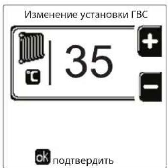

pnc.14
PerynnpobkataemepaatypblrBC (npu HauynuBHeuHero 6oJnepa)
BoiDte B MeHIO "TemnepaTpya perynpoBkn" nIe N3MeHeHnIa TemnepaTpybI OT MmHMym 10°C Do MaKcMym 65°C. NpOttBePdTe KhoNkoK Ok.

Kotel npojaetc c HeaKTNBbIM rpaqukom pa60Tbl.
CneIOBaTeIbHO, B Cnyuae 3anpoca 3TO 3HaueHne NocnykNT yCTaBkoI.
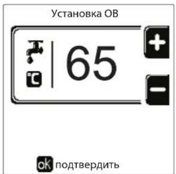

pnc.15
ChnHexHe TemnepeTpybI BC (npu yctaHOBJeHHOM donoJHHTeJbHOM 6ouNepe)
BoiDHTe B MeHIO "ToHxHeHne TempeaTpybl peRynpOBKn"IJI N3MeHHeHNe TEMpeaTpybl OT MHNMyM 0^ do MaKcMym50°C. IOnTBePdTe KHOJIKOk OK.

3TOT npametnp nCnoIb3yeTcra, TOnbko ecnn BkNoeHn nporpammmpoBaHne rpaqNka pa60tbo no yacam. Cm. "PporpammmpoBaHne rpaqNka pa60tbo no yacam" on page 281


pnc.16
IporpaMmnpoBaHne rpaΦnka pa6Otbl no Yacam
IporpamnpoBaHne rpaKa pa6oTbI no Yacam BblnoJIHReTCr OndHaKOBOKAKnOToJIeHn,TKnDnYFBC;DbE nporpaMbly ABNIOCTc He3aBNCmbm.
YTo6b3aIporpaMMnpoBaTb OToJIeHne,BoIInTe B MeHIO «TpaΦNK pa6OtBi» no MapuPyTu «MEHIO IOnJIb3OBATEJIA "OTOnJIeHHe" "TpaΦNK pa6OtBi".
YTo6b3aPpOpaMmPoBaTb BC, BOIInTe B MeHIO «rpaΦnK pa6oTb» NO MapuTy «MEHIO NOLb3OBATEJIa “TOPRAEE BOIOCHA5XEHNIE" "rpaΦnK pa6oTb".
BbEpTe TIN nporpamMPOBaHnI, KOtOpoe HyKHO BbInONHHTb, INcJeDyTe IHCTpyKUm, OINCAHHbIM HIXe.
Bb6epTe DeHb (pnc. 17) nnnnHTepBa n3 HeckoNkx Dne nn nporpaMMpoBaHn (pnc. 18) nnoTbePnt KhoNKo OK.
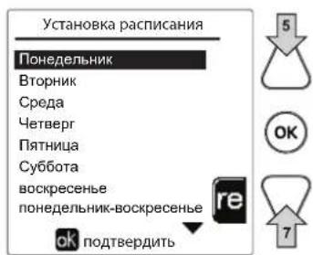
puc.17
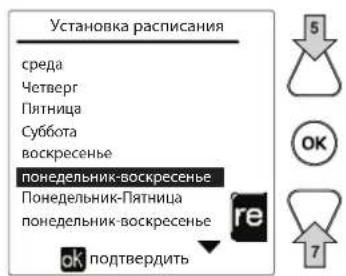
pnc.18
PpOpaMMA OTHOCNTCA K HeeHbHOMy Tnny: 3TO O3Haayet, YTO nA KaJdOro DnH HeeEIN (PNC.19) MoKHO 3aDaTb 6 He3aBcIMbIX BpeMeHHbIX INHTepBaIob; dNRA KaJdOro BpeMeHHoro INHTepBaIa Bbl MoKeTe Bbl6paTb 4 Onm:
BKN. B cnuyae 3anpoca Ha otponneHnE/ΓBC KOteI pa6oTaET C 3aHaHHo TEmpepaTypoI perynpOBKn OToJIeHnA/ΓBC (pnc. 13/pnc.15).
B cnlyae 3anpoca Ha otonneHne/ΓBC koteJ pa6oTaet Ha noHNKeHHoTemnepaType perynpOBKn. NoHNKeHHaTeMnepaTypa nOyuaeTcBbHTaHEm 3aueHn "NoHNKeHne TmnpaTpby perynpOBKn" (pnc. 14/pnc. 16) n3 3aueHn 3aDaHHo "TemnpaTpby perynpOBKn" oToonneHna/ΓBC (pnc. 13/pnc. 15).
BbIKN. B cIyuae 3anpoca Ha OtonneHHe IBC KOten He BKnOuaeTe pexm OtonneHn/IBC
- --BbIKn..BpeMeHHoN INTEpBaN OTKnHoyeN.

Koten npoaeTcH eAeKTHBbIM rpaFmKOM pa6oTbI. N deiCTBnTeNbHO, Heo6xOIMO 6ydt 3anporpamMPOBaT b KaJbI DeHb c 00:00 do 24:00 B pexHMe BKJI. (pnc. 19).
Chayana yctaHOBtBe BpMa HauAna nepBoro BpeMeHHoro INTepBaIa (PNC. 19) c nOMOuBIO KOHTeKCTHBIX KHOHOK 1 n 2.
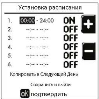
pnc.19
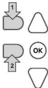
HaxmTe KhoNky Habraun 7, To6bI nepeTn Ko BpemEno OKOHaHnepBoro BpemEHoro INTEpBa n (Pnc.20), n yCTaHOBeTe erHa JKeJaemoe 3HaueHne c NOMOsbIO KOHTeKCTbIX KnaBn1 1 n 2.
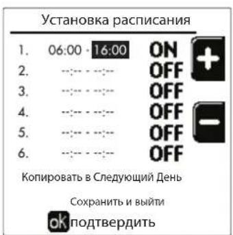
pnc.20
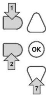
Haxmnte KhONky HABrAun 7 nCnOnb3yNe KeKHTeKCTHble KhONk 1 n 2, YTO6bl 3aDaTb peXIM pa60Tb B TeueHne nepBOrO BpeMeHHoro INTEPbana (pnc.21).
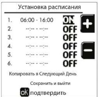
pnc.21
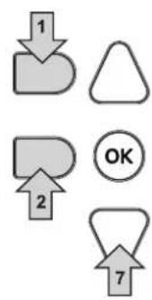
3aTeM Haxmte KhoNky Habraun 7, YTo6bI 3aDaTb (Pn Heo6xOIMocTn) CJeDyIOUne BpeMeHHbIe INTePbaJIb (pnc. 22, pnc. 23 n pnc. 24).
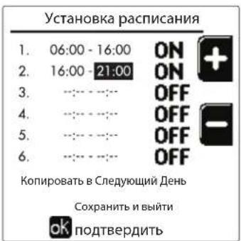
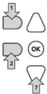

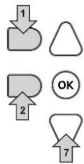

pnc.22 pnc.23
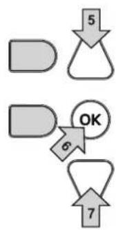
pnc.24
Korda denb 6ydt 3anporpaMMPOBaH, HAKMITE KONky OK; ABTomatueckn 6ydt Bb6pHaNo3uNra «CoxpaHtB n BbInr (pnc.25). NcnoIb3yIte KONKn Habraun 5 n 7, YTObbl N3MeHNTb npdebluyne HactpoKN, INn HAKMTe OK nnd noTBePKeHn: B 30m Cnyae DnCnpe BepHeTcK OTo6paKHeHNO dH (pnc.17) nn INTEpbana n3 HeckoJIbKnx DHei, KOToBbl HxHyO 3anporpaMMPOBaTb (pnc.18). 3aTeM MoXHO 6ydt BblONHtB Ty Jxe npocedpy, YTObbl 3abepHtB XeNaEMy Ho HeDeIbHyIO nporpaMMy.
Ecnn BbXOTNE 3anporpammmpoBaTcneyUounNeHb TaKIM Xe o6pa3OM, Bb6epNTe «CkOnnpoBaT Ha cneyuouuN DeHb» N HaxMMTE OK nIaNoTBePckDeHn (pnc.25).
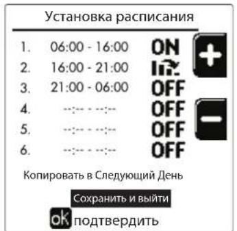
pnc.25

YTO6bI BOCCTaHOBNTb 3aBOIDCKne 3HaueHnraPpKa pa6oTbI, HAKMITE KOHTeKCTHYIO KhONky 3B MeHIO rpaΦnk pa6oTbI (pnc.26) nnoTBepeNTe C NMOU bIO OK.
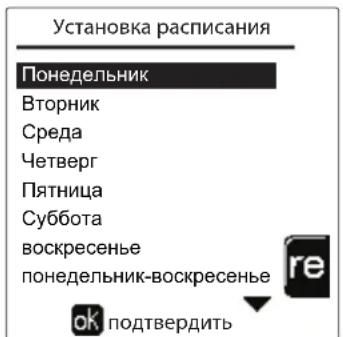
pnc.26


Ie yacobbe nporpaMMbOtonnHn IBC He3aBNCMbI daKe B cIyae Bo3BpTa K 3aBoDcKIM 3HaueHnM.
IporpaMMnpOBaHne yHKUNN «JIerHOHeNa» (c ycTaHOBJIeHHbIM kaKbTaTINHBbIM 6oJIePOM)
YTo6bI BKNIOHTb FyHKUHIO ANTHINERHOHeJIb, Heo6xOJIMO ycTaHOBnTb npaMeTp P23 B TEXHNUECKOM MEHIO Ha BblKl.. IInpOrpaMMIOBaoHHFyHKUHIO Heo6xOJIMO BOITB MeHIO "JernnoHenna" no MapuTy «MEHIO NOLb3OBATEJI. "TOPRAEE BOIOCHABXKEHIE" «JernoHenna".
B 3TOM MEHIO Bbl MOKeTe 3aDaTb CneDyUOuNe npaMeTpbl:
- DeHb «AntunnernoHnbl». OnpeJeIeT DeHb HeJeN, B TeueHne KoToPoRo ΦyHKUra 6yIeT aKTHBnpoBaHa. ΦyHKUIO MOxHOaKTNBnPOBaT TOJbKO OINH PA3 B HeJeNIO.
BpemrAHTnnernoHJIbI).OnpeJeT BpemHaayana DeiCTBna yHKun. - PpOdoJXKHTenbHocTb《AHTnIeRnoHeNbI》. OnpeDeneT npOdoJXKHTeJIbHOCTb (B MmHyTaX) DeIcTBnФyHKUIN.
Temn. perynipobkn AHTnJIerHoneJIbI).OnpeJeT tempeatypy perynipobkn BC BO Bpemr deiCTBn yHKm.

BHIMAHNE
BpeKmE ECO yHKnHa He aKTHBHa.
-Функця AntunnernoHeIbI 6ydeT aKTHBHa, TOnbKO ecJI KOTeJ yCTaHOBJeH B《ABTomatNueckn》peXIM (O) IN TOJIbKO BO BpeMeHHbI eHTepBaJIbI, 3aDaHHbIe Ha BKI. nII Na «ПонIxehHЯ TemnepaTypa» (1).
B npotnbHOM cnyuae, BO BpeMeHHbIe dnaana3oHbI, KOrda KOteJ yCTaHOBJIeH Ha BblKn., fynkun, daKe ecn OHa 6bla 3aHa, He 6ydt AKTNBipObaHa.
B pexime otnycka ( ) cyHKnAHTUNeHNoHeJIbI aKTNBHa.
- Ecnn 0yHKnna
«Аntилгнонела» He
BbINHReTc npabNbHO, Ha
DINCIJIeI IOBNTCJ
coo6ueHHe, noka3aHHoe Ha
pnc.27.Джжпрннанчи
3Toro COO6eHnKOTeI
npoJONKNT nCpabHO
pa6oTaTb.
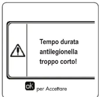
pnc.27-Coo6ueHHe o HeBbInOpHeHHn FyHKcH N «AHTnIerHoHenna

TemnepaTpa, 3aHaHnaepe3 «Temn. perynpobkn «AHTnnernoHnbl》,HE doJxha 6bItb BbIe MaKcMaIbHO TemnepaTpbi perynipOBKn TBC, yCTaHOBneHHo c nOmoUb npametpa P19 b TEXHnueCKOM MEHIO.

Ecnn B cnCTme YeTaHOBnEH nPKyIaHNoHHb HACOC dNp KpyLauu BObl BO BpeM DeeCTBna FyHKunn «AntnnernoHnbl》,Heo6xOJIMo yCtAHOBnt NapamTp b08 Ha 1. TaKm O6pa3OM, KOHTAKT MeKdy KJIeMMAMn 9-10 (no3.300-pnc.95,pnc.96 n pnc.97) 3amblaKaTe npn AKTBAuun FyHKunn.
ФункURAOTNYCKA
BoiTe B MeHIO “FyHKLJN OTNYCKA" no MapupyTu "MEHIO NJIb3OBATEJRA "FyHKLJN OTNYCKA", 706bI 3aJaTb:
-Дату Нача отпсka.
-ДаTy OKOHuaHnO TnPycka.
Ha dncnnee Moryr noBNTcra DbA Tnna NkOHK:
-ФункцЯОТпусякzaЗ苹рограмміюваHa,Ho He aKTHINBPOBaHa.
-Функцу Otnycka paobotaet. Koto 6ydt paobotb, kak B pexmMax JTo u 3KOHOMN (c yctaHOBNEHHbIMФakyltaTnBhIM BoINepom).
OcTaIOCTaPbOuHmM FyHKnI npOTNB OeJeHeHn IeHnOHeHa (ecn OHa aKTHBIpObaHa).
Data npoBeHn cepBnchbix onepaun
3Ta INHOPMaunn NOMoAe TNOHb, KOra cpa6oTalo OOnBSeHne O Heo6xOuMocn npOBeHn PnaHOBOrTO. 3To rBnEeTc HcRHaHn3aueo HEnoNaKe, a npocTo npEynpeKdEHNm. No nCTeHnn 3ToJ daTb KaKdb pa3 npn BxOe B rIaNHOe MeHO KOteN BbIEeT 3KpAHHOe OKo C HAnOMHHnem O Heo6xOuMocn PnaHOBOrTO.
HΦopMaun o CepBnchOn cnx6e
HnHpa HnHpMaun CoepKNT Hmep TepeHa, no KOTOpMy MoXHO CB3aTbC8 B Cnyae Heo6xoDmOi NMOU (ecnn 3anporpammpnoBaHO cneuaNtOM).
PerynipoBka TemnepaTypbI Bo3dyxa B nomeueHn (c nomoouOOnuOHoro KOMHaTHORo TepMoCTata)
3aadaTe c NOMOJIbTO TepMOCTaTa TEMpePaTybI Bo3dYxa B NOMEUeHn HJxHyU ToMnepaTpy BHyTpNI NOMEUeHn.
PerynipoBkA TemnepaTypbI BO3dyxa B nomeueHnn (c nOmoob OOnuOHoro yCTpoiCTBa Dy C TaHemepom)
3aadaTe c nmooub yctpoCTBa Dc TaHMePOM HxKHyTo Tempeatpy BHTPN NOMEeHn. KToen 6yTeN NOdepkmbTbTemepatpy BoDbB CNTMe, Heo6xoDmMyIO Ira OBeCneueHn B NOMEeHn 3aDaHHo TEmpeatpyBo3dyxa. B Tom, tKaacaetcpa60tB KoTna C yctpoCTBOM Dc TaHMePOM, CM. COOTBEcTBByUOyIO NHCtpKuHn Ha 3TO yCTPOIcTBO.
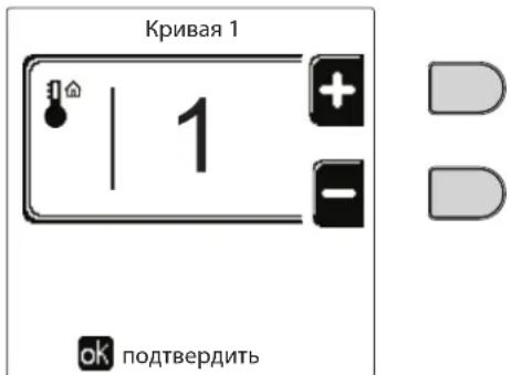
pnc.28-KomnEhcaunOHna KpNBa
Otperynpyte npapannelbHoe cmeueHne Kpmbx ot 20 do 60^ (pnc.31), nCnoJIb3yra npametp "Offset1", nnoTbePnte knaBwEi OK.
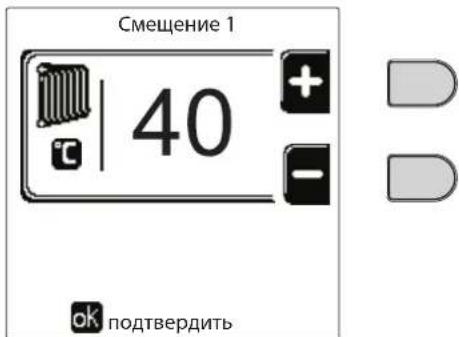
pnc.29- PapanneIbHoe cMeueHne KPNBbIX
Ecnn TemnepaTpy B nomuehenn OkazbIaeTcH Hxke XeJAEMO, peKOMEnyTeTcBbl6paTb XapakTePncTuKy 60one BbcOKoro npraika Hao6oPoT. YBeHHBaar nn yMeHbwa Ha ONDHy eHNuTy nopAOK KpNBOn, OceHHTe, KaKM o6pa3om 3TO cKaXeTcH BaENHHe TemnepaTpby B nomuehenn.

pnc.30-KomneHcaunOHhIe KPNBbIe
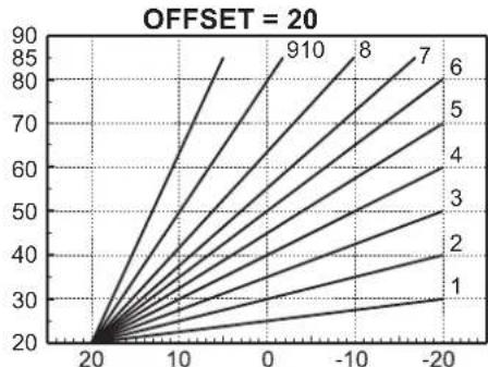
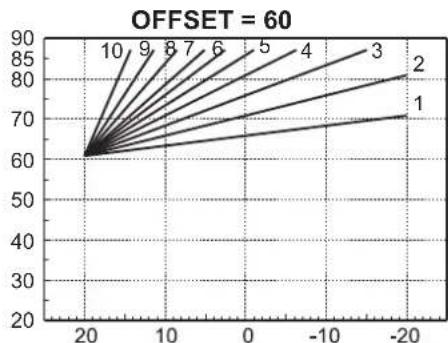
pnc.31- Pnpme npaannenbHoro cmeuenn KOMNEHcaUHOHHbIX KPNBbIX

3TOT npametnp nnonb3yeTc, TOnbKO eCNn BKNIOeHO nporpammpoBaHne rpaFka pa6tbo no yacam. CM. "PporpammpoBaHne rpaFka pa6tbo no yacam" on page 281
Hapyxhna temnepaotypapeynilpoBaHnBblKJ.
BoiHTE B MeHIO "Hap TeMn OToNN BbIKN",yTo6blakTNBnPoBaTb FyHKnIO:OT 7°C Do 30°C.
BakTHHOM COCTOHH 3Ta cyHKUaOTKIOuAET 3aIPOC Ha OTONNEHnKaXdb pa3, KOrDa TEMNepaTpy, N3MepeHHa HApxKbIM DaTCHKOM, npeBbIaet 3anporpammmopBaHoe 3aueHne.
3anpoc Ha OToIeHHe BHOb aKTHBnpyetcKa KaTolbKO TeMnepaTypa, NImpeHHa HApYXhIM DaTCHKOM, OKaXeTcHnKe 3anporpaMMPOBaHOrO 3HaueHIn.
PerynpoBaHne c dncTaunOHoro nyIbTa ynpaBHeHna C TaMepom

Ecn KOTny nOcknoeHyo yctpoCTBO dIcTaHIOHO rO npaBHeNr C TaImePOM (Onn), BblweonncHbIe perynpobKn npo3BOJATCR B COOTBeTCTBN C yka3AHnMn, npuBeDeHNbIMn B Tabnca 1.
Ta6nua 1
| PergunpoBkA Tempeatypbl BODbl B cnCTeme OTONJIENIA | PergunpoBkU MOxHOb IprO3BeCTn KaK I3 MeHIO pIyIbTa Dc TaimePoM, TaK i c PAnHeN ynpaBJIeHnRA KOTlOM. |
| PergunpoBkA Tempeatypbl ΓBC (pni hAIInuH N BHeSHero 6oIIePa) | PergunpoBkU MOxHOb IprO3BeCTn KaK I3 MeHIO pIyIbTa Dc TaimePoM, TaK i c PAnHeN ynpaBJIeHnRA KOTlOM. |
| IpeKIIouHe nE peXIMOB "JIeTo"/ "3IMMa" | JIeTHN IPEXIM IMeEIT IprOpHTET nepeD BO3MOxHbIM 3aIpcOCom Ha OTONJIeHnE OIT PUY C TaimePoM. |
| BbIbOp Eco/Comfort (c UcTAHOBJIeHbIM DoIOnIHNTeJIbHbIM 6oiIePOM) | Ppi OTKIIouHeN IPRC BIC I3 MeHIO pIyIbTa Dc TaimePoM KOTeN IpeXODHT B PEXIM Eco-nomy. B 3OTOM COStOAHN KHNKNa PO3. 10 - pnc. 1 Na HeN I KOTna OTKIIouHeA. |
| Ppi BcIIouHeN IPEXIMA ΓBC c UcTpoiCTBa Dc Yc TaimePoM KOTeN UcTaNAbNIbaeTcB PEXIM COMfort. B 3OTOM COStOAHN C NOMOuIbKO HKNKNa PO3. 10 - pnc. 1 Na HeN I KOTnAm OMeHX BbIbPaTb OdINH I3 DBYx PEXIMOB. | |
| Плаваоця Tempeatypa | Kak pIyIb T Dc TaimePoM, TaK I PraT a KOTnA ynpaBJIaHOT perGriNPOBkoI pIpaBaIoUeIe TeMpepaTypbl: IprOpHTeHNO I3 HIX YaBJIaTeTc PIIaBAIoUaIe TempepaTpya PIIaTb KOTnA. |
PerynnpOBka daBneHn BOnbI B CnCTeMe
DabnHe 3anpabKn XoJIOHO CNCTeMbI DOJXHO coCTaBnTb np6n3nteBHo 1,0 6ap. Ecnn daBnHe B CNTeMe ynaTe HNKe MNHmAlbHo DOnyCTMOrO 3Naehn, 6NoK ynpabNeHn KOTnOM AKTNBPpyet Own6ky 37 nHomep Moyn (Pnc. 32).

Nocne BocTaHOBHeHn DaBHeHn B CnCTeMe KOTen AKTNbpyet cNKc Ncycka BO3dYxa n3 CnCTeMb: OH 6yDet dNtbcra 300 cekynd, npn 3Tom Ha DcCnnee 6yDet BbcBeHuBaTbCnmbON FH.
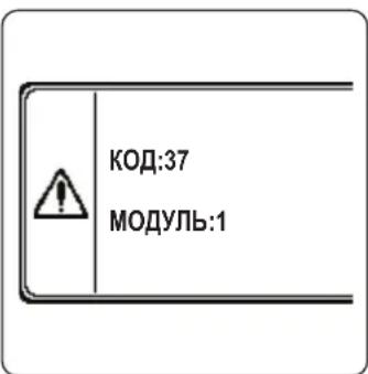
pnc.32-Onmbka HeoocTaOuHOro DaBneHnBa Moynye 1 cncTeMbI.
2. YctaHOBka
2.1 Yukazannaya oseero xapaktepa
YCTAHOBKA HACTPOIKA KOTJIA DOJIJKHA OCUJECTBJIYTBcT OJbKO CNEUJAIN3NPOBAHbIM NEPCOHAIOM, IMEIOUMI NPOBEPEHHyO KBALINΦKAKUIO, PPN COBJHODEHN BCEX PNIBEDEHHbIX B HACTORIeM TEXHueCKOM PYKOBOCDTE YKA3AHNI, PEPINCAHNI DEIECTBYIOE 3AKOHODATEJBCTBA, NOLOXEHNI HALIOHAlbHbIX IN MECTbIX HOPM IN PPABIN, IN B COOTBETCTBmC PPNHATbIMI TEXHnueCKIMN TPE5OBAHnAIMN.
Iy Ieauapnn doJXhbl npmeHbTcne cJeDyoUune cTaHapTbI n peKoMeHdaun no yTaHOBKe:
SVGW-npHnbl,ra3G1:yctaHObKa ra3oBOro 06OpyObaHHa
- EKAS -Форм. 1942: Дуpeктуba no Схиненьюу raу, часы 2
KaHToHaJIbHbIe 3aKOHbI HOpMaTHBbIe aKTbI (HaNPmEp, npabuna noXapHO6e3OnaCHOCTn)
OPERAToTeNoBReHepaTOp,npedHa3NaueHHbIINpa60TbOtDJIbHOIN BKaKaDHOM NoKJIOeHHN (6aTape).
FERROI npedocTabnre no 3anpocy Bcno rpoTeXnueckyo apMaType n DbMoBBe KOnneKTopbl nna noDcoeHHeHn2 nnn 3 arperatOB no kackaHoi cxeme B KOhpypaunx O7 + 70 KBT do 450 + 450 + 450 KBT.
Korda rehepatopby OPERA yctahabnbaotcno kackaHoh cxeme cncnoIb3oBaHHem npnaHdxNcoHcTe, npedycmptpeHHx FER-ROLI, heo6xoJIMO, 706b6bln BblnoJIeHNbBce Tpe6oBAHn, HanaeraMbe DeJeCTBOUIMn CTanapTAMn npabINamn, npimeHMblmK 3OTMy KKBNAEHTHOy" rHePATOPy o6uei TeNOBO MOUHOCTN. B aactHOCTN, yctpoCTBA 6eONACOCTN n CNTema BblOda bIMOBXt RaOB N OMeUeHN YcTAHOBKn DOJIKNb COOTBeCTBOBaTB 6oei TeIOBO MOUHOCTN BaTapei arperaTOB. PpeINCAHn, npBeDeHNbB daHAnp ykoBDCTBE, OTHOCTCB K KO INHOHOMy arperaty, TAK N K arperaTM B KacaHOM NOkKnIOeHn. DOnOpNItehny InHOFOpMaun BO tHOtOHeHN yCTAOHn TEINOREHepaTOB NO kackaHoh cxMe MoKHO HAIIN B COOTBeTCTByouem pkyoBODCTBE, npinaraIOeMcK KOMIINEKTAM nJa KACKaHORO NOkKnIOeHn.

3JIeKTOHbIe KOMHOHeTbI KOYkAT DnI ynpaBHeHMaKc.6 arperaTaMn B KACKaHOM noKnIOueHm. Ppi co3dHm CNTEM NO KAKaHoi CXeme, BKNIOaHoux BoJee Tpex arperatoB, 6e3 nCNOb3OBAHn npHaNDekHOCTe, npEDyCMOTpeHHbIX FERROLI, Heo6XoIMMo NDoTobNtB rNpaBInueckne/ra3OBBe IONKeTOpbl COOTBeCTByUOxip pa3MePoB, OchaSeHHbIe BCEm IpeDOxpaHTeNbHbIM UcTPOCTBaAM DeiCTBYIOUM HOPMaMn a TAKKE OTDeIbHbIe dbIMOXOdbI INN DbMOBBe KOnNEKToPbI, pacCHHTaHHBe KBaINΦuIPoBAHbIM CneuaJIACTOM.
2.2 MecTo yCTaHOBKn
KoTeI OJKeH 6b1b yCTaHOBHe B CneuaNbHo OTBeDeHOM DnIe3ToIeI NOMEueHN, IMeIOeB EHTINRAIOHHe OTBepTna, COO6uaOuHneC HApYkHO aTMocpePoe B COOTBEcTBn C DeIeCTByUOUMn HopMaMn. ECIN B NOMEueHN yCTaHOBHe bpyrne RopeJIKN IIN BYITXHbE YcTOPOCTBa, KOTOpBE MOryT paBOTaTb ONDOBpeMeHNO, TO BEHTINRAIOHHe OTBepTna DOJHXbIMeTb pa3MepbI, oObecNeuBAUOE ONDOBpeMeHHy IOpaOTy BCEx arperaTOB. B IIObOM clyAae, B MeCeY cTahOBKn DOJHXbI OTCytCTBOBaTb ORheONaChbIpe PdeMeTb IIN MaTePnAnbI, eKne ra3bl, IIbN IeTyue BeIeCTBa. NOMEueHne DOJHXo 6b1b cyxIM n He NOBepRaTbc Bo3dEChTBNo DoJxra, Chera IIN Mopo3a. Ppi pa3MeueHN OCTabTe BOKpy annapata DoCTaTOHmecTa, T06bl OBeceHHTp POBeDEHnTE XEHueckoro 6cNyKBaHn. B qACTHOCTn, y6eDInTeCB, YTO DBepa RopeJIKN MOKeT BeCnpenTCTBeHHO OTKpbIBaTcBcR.
2.3 Tnpabnueckne noKIOUeHna
Tennobon notehuaarperata onpeenraetc3apahee nytem paeta notpebocn 3daHmB tenne cornacho deectbyuim HopMa. Iy oecneuehna npabnlbhoro n Haedxhoro fynkunohnpobahn Cnctema dOnjHa 6blb cchaeneha BCEMn HeoXoIMbIMn 3IeMeHTaMn. B acThocn doJnxhl b6blt yCTaHOBHeHb BCE npdeoxpaHntbHbie n 3auNTbte yCTpoCTBa, npedyCMOTpeHHbe DeiCTByIOUHMn HopMaMn DnKOMNKeTHbIX MOylbHbIX reHepaTOPB. DaHbte yCTPOCTBA DoJHKb6blb yCTaHOBHeHb HA HarHeTaTeNbHom TpyoBpOBoTe ropye Bobl cpa3y nocne noCneHero Modyn Ha pacctOaHn He 60nee 0,5 M 6e3 yCTaHOBKn OTceHybix yCTPOCTB. Arperat noctablaertc 6e3 paunipTeHboro 6aka n npdoxpanhtbHoro knanaHa, NnoKNHOe HBe O3JIaraetc Ha MoHTaxHnka.
DAnHHb arperat MoKet NcnpaBHO pa6oTaB npn MmHmAbHom pacxOe O nH He Tpe6yET NOCT-UPKyIaUNI yCTpaHHe TENBOB INepu. Co cblko Ha nap. 3.3. R3F c6OpHK R BbInyck 2009" BpemnoCT-UPkYIaUN, ppeDnncAHoe npOn3BODHTenEM, coCTabJIeT, cneIOBaTeNbHO, 0 cekyHd.

CnIBHOe OTBepCTne npedeoxpahntbHoro Knaana HdoJXHO 6bITb coEINHeo C BOPOHKo IIN KAHAUN3aueNe BO N36exAHne nonadHna BObl Ha nO B cnyae cpabTBaHNN KNAHn npn npebblweHHn daBHeHHN B OTONTeHBNO CNCTeme. B npOTNBOM cnyae n3ROTOBNTb KOTNa He HecET HNKAKO OTBeTCTBEHNOCHTn 3a 3aToPJIeHne NOMeUeHHn npn cpaTaBHAAHn npedeoxpahntbHoro KnaanaHa.
He nCnoJb3yIe Tpy6bl rIdpabBnuecknx CnCTem dIa3eMneHna 3JIeKtpnuecknx np6opOB.

Ipeed yctahOBKO TzateBHO npomoe BCE Tpy6bICCTeMbI, YTO6bl ydaNTb OTLOXeHn Hnn 3aarp3HeHHN, KOToPbIE MOryT OTpuaTeNbHO cKa3aTbcra Ha pa6ote KOTna. IcnoJIb3yIte xHmUeCKne npcaADKn, NOxOJaune dIra 3TxN ceJe, To eCtB, CNoCo6HbIe ydaJIaTB CO CTeHOK n DHa Tpy6OpBOoDB N dpYnx KOMNOHETOB CNCTeMbI UJnAM, OKCNDbI MeTaIIIOB, a n3 Hn3KOTemMepaTpHyix CNCTeMaKKe BnOMaccBl, NyTe mPoCToN cIpKyJauCIN BOdbI B rOpaye n/nn XOnoHDHcCTeMe. He cNeDuET nCNoJIb3OBA Tb cpeDCTBa, KOTopbIE MOrY Pa3BeDaT n/nn BBi3BaT b Koppo3H0 MeTaIIIOB/IINaCTIKOBbIX MaTePnaNoB, a TaKke cyueCTBeHHO n3MeHЯTb npipOndh PH BoDi.

Kpome 3TORO, Heo6xOJIMO npedymOTpeT yCTaHOBky fNtbpHa o6paTHOM Tpy6oPBODe CnCTeMb BO n36exKaHne IOnaHaHnI n3 HeE B KOTeI rpa3n nnI IJama, MOryux Bb3BaTb 3acOpHe HnI NOBpeXdHn TENPOHEpaTOpOB.
YCTAHOBKa ФИЛБТРа RAIBIeTcR CTpORO O6ra3aTeJIbHOB B Cnyaee 3aMeHbI REHEPATOPOB CyUeCTByIOUx CNCTeM. IV3rOToBnTEJIb CHIMaET C Ce6BaBCaKyIO OTBeTCTBEHHOCt 3a NOBpeXdEHNe KOTJa No pNUnHe OTCyTCTBnA INJIN HePpaBnJIbHOYCTAHOBKn BblIeUYka3aHHOrOФИbTpRa.
BbIIOJIHHTe NOdKIOUHeH N K COOTBeTCTByIOUIM TOHKAM, KaN IOKa3aHO Ha pncyHKe B SEZ. 4.1 n corNaCHO CnMBoJAM, IMeOuIMcRA Ha camOM aperate.
Ta6nua 2- PA3MEPbl COEINHEHNI
| MOДЕЛь | 70 | 125 | 160 220 | 320 | 450 |
| П一步一步 в систему | 1" 1/4 c peзбов | 1" 1/4 c peзбов | 2" c peзбов | DN65 c Фланцаму | DN65 c Фланцаму |
| ВозвратульkoNTур палавно системы/HИЗКАЯ TEMПЕРATУРA | 1" 1/4 c peзбов | 1" 1/4 c peзбов | 2" c peзбов | DN65 c Фланцаму | DN65 c Фланцаму |
| П一步一步 заа | 3/4" c peзбов | 1" c peзбов | 1" c peзбов | 1" 1/4 c peзбов | 1" 1/2 c peзбов |
B cnlyae napaJIeIbHoro MOHTaKa Heo6xOIMmo npedyCMoTeTb RnDpaBNIueCKOM KOHType KaKDoR OToCHoN KJIaHaN C npIBODom (ynpabIembl arperatOM, cm. 3neKTpuYeckyIO cxemy pnc.95) dna npedotBpaUeHnI o6paTHo NpKpynIuN B hep6toauoi kotei.
Kpome Toro, Heo6xOIMO npedycmOTpeb OTdeIbHbI npedoxpaHTeIbHbI Klaanah Ira KaJdoR KOITBa COOTBeTCTBnC npednncAHmN3 "C6opnka R".
C 3ToI cIeIbIO NO OTdIeNbHOMy 3aKa3y NoCTaBnIOTcIe dyIOUne KOMIIeKtbl:
052000X0 -ДРОССЕЛБНКПАПАС ПИВОДOM DN50
052001X0 -ДЮССЕЛБНКПАНС ПИВОДOM DN65
Ecnn perynipobka paonpeenntbno yctahOBKn He 3aBnCT O TneKtpoHNo CnCTeMbI ynpabNeHHN KOtNaMn, peKomeHnyetc BblONHHTb 6aInac Mekdy Tpy6am N Odaun N Bo3Bpata H3 CnCTeMbI dln 3aUnTbI UnpkyraHOHHbx Hacocob.
XapakTepnCTKIN BODI I BCNTeMe
Ipepe yctahOBKO rHeepaTopo OPERA CnCTema, 6yNb OHa HOBOI Iyke 3KcPiNyATnpyEmo, DOnJHb 6bTB DOnJHbIM oBpa30m Ounuhe, YTObI ydaNtB 3arp3HeHH, OCTabUneCnOnc MeTAXa, PACTBOpNTeIN, UJAM n 3arp3HIOUe BeueCTBa B CEJOM, NocOKlbky OH MOrTy HApuyTb 3oFekTNBHOCTb 3aUnTHbIX KOHNIOHNPYIOUX npicaDok. NcNoJIb3yIte HeHtpaBhble HarepeccNBbIe uCTraIe CpedCTBa dIpyuCTKn MetanIIuecknx, pe3HOBbIX n PnaCTNKOBbIX deTaane rehepaTopa/CnCTembl. OnopoxHnTe, npomToE n 3apabBe TcCTemy B COOTBeCTBn C HKeCENe dyIOUMM INHCTpyKUIMM. 3arp3HeHHa CnCTema He rapaHTnpyeT 3aBHeHHb cPCK kCNPIyataunrrehepatopa daXe npi NcNoJIb3OBAHm 3aUnTHbIX KOHNIOHpyOUX npicaDok.

KoTJIb OPERA NOxOJr T Jn yCTaHOBKn B OTONIteJbHbIX CnCTeMax C He3HaHTeJbHbIM IOnaDahm E KcNOpOda (CM. CnCTeMb "BapnaHT", CTaHdapt EN14868). B CnCTeMax C HnpepbIBhm (HaNP., HAnOJbHbIe CnCTeMb 6e3 Tpy6, IpeDOrTbPaauOuX paccenBaHne TeNJa, INN B OTKpbITbIX CnCTeMax) ININ nepNoDiueckm (YacToe NOnONHeHne BOdbI) NOnaDaHmE KcNOpOda Heo6xOdmo IpeDycmOTpeTb Qn3NuYeCKyU cenapaunIO (HaNP., C NOMOuBIO PnactInHuTaTO TENNOOBMeHHnka).
Boda Bnytpn OTONNTeJIbHO KOHTypa DOJXHa 6bITb Opb6OtaHa B COOTBeTCTBnC Tpe6OBaHnM N DeIcTByUoXx 3aKOHOB HOpM, IMeTb XapaKTepNCTNKu, yka3aHHbIe B CTAHdApTe UNI 8065, n OTBeuTaB IpeDncaHnM CTAHdApTa EN14868 (3aunTa MeTaNHecknx MaTePnaJIOB OT KoppO3nn).
Boda dna 3anoHHe (nepBoe 3anoHHe n noCneDyUoIe DOnBB) doJXHa 6bTB NITBeBO, PpO3paHoi, C XecKcKbIO He BIIe Yka3aHHoB H HxKePnBedeHHo TaBnue, a TAKKe o6pa6oTaHHo KONHnOHOHPOBaHHo CpeCTBaMn, peKOMeHDoBAHHbIMn PpOH3BOOnTeMeM (CM. HIXeCNeDyUoIcn CnOCOK) BO H36ExAHHe O6pa3OBaHHa OTNoKeHn, Ra3OB, KoppO3HN, arPeCCNBHorO BO3DeICTBn HA MeTAnuHeckne IPiactMacCOBble KOMnoHEHTb rEHePAToPA BCen CnCTEmbl, a B HN3KOTempeAtpHBIX CnCTEmax - 6akTePnAabhix INMI MKNpO6bHix Macc.
Boda, codepkaaara B cnCTMe, a TAKKe I06abnma B Oda, dONKbI nepnoDmueckn npOBeprbcn (PnK kaxdom 3anycke yctahOBKn, nocLe KaKDoro Upe3BbUaHOro BMeuataeNbCTBa, taKOro KaK, HApimep, 3ameHa reHepaTopa INJ dpYnx KOMNOHEHTOB CnCTembl, a TAKKe, no KpaiHne Mepe, oIN Pa3 rO Go BPeMra PAnHOBbIX pa60 TnTexHnueckomy ObcnykuaHIO B COOTBeTCTBmC tpe6oBaHnMa CTanapTa UNI 8065). Boda doJxHa 6bItb npO3paHOn n OTBeuATb Tpe6oBaHnAm, npBedeHHbIM B HnkeCneJeUoie Ta6nue.
XHMMUeCKN KOHNIOHep B HeoCTaTOOH KOHcHTpaUNn He CMOKET rapaHTnpOBaTb 3aunTy, dnn oBeceueHnKOTOpOu OH 6blBVeDeH BCNTemy.
Bcerda npOBepaTe KOHcHTpaunO cpeCTBa nocLe KaKDoRO BBeDeHnI nepNoDnueckn He pEke Ondoro pa3a B rOid, NOpUyAra 3To KBaINΦuNpOBaHHOMy TexNHueckomy nepcoHaNy n3 HaWei ABTOPn3OBaHHo CepBnCHo CETn.
Ta6nua 3-PekomeHdyembIe XmNueckne KOHNuOnHpyoUne npcaaKn,doctynbIe B HaSei ABTOPn3OBaHHoCepBnCHOcTn
Bounte B "MeHIO npaMeTPOB" nyTe HauKaTna Ha KnAbuWy OK.

pnc.35
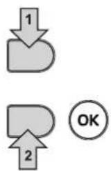
BoiDnTe B "MeHIO KOHOFUpyaun" INB "MeHIO TINa CNTeMbI" B 3aBNCMOCTH OT I3MeHReMOro NapaMeTpa, KaK NOKa3aHO B KaXdOM npIMpe RnDpaBnueckoro KOnTypa.
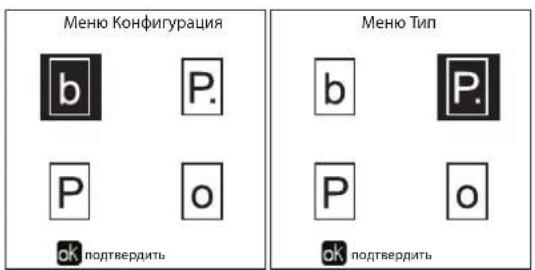
pnc.36
Да npЯMbIX KOHTya OToJIeHnIa
-Пинциальнахema
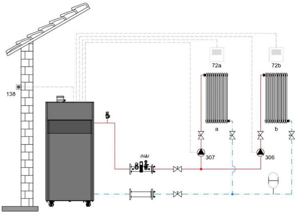
pnc.37
-3NeKtpnueckne coeHHeHH
Pocne MoHTaKa 6ydt Heo6xOIMo BbINOJHnTb Heo6xOIMMbIe 3NeKTPnueckne NODJIIOUeHna, KaK NOKa3aHO Ha 3NEKTPnueckoCxeme.
Bcne 3a 3TNMBbINHHTe KOHnpyauu6NokaynpaBHeNc corlacho yka3aHnM COOTBeCTbyoUero npaparpa.

pnc.38
CneuΦkaun (pnc.37 npc.38)
72 KomhaTbI TepMoCTaT 1-30HbI (PpMOrO KOHTyPa)
72b KomHaTHbIe TepMoCTaT 2-30HbI (npamrO KoHTypa)
138 DaTnK HApyKHOI TeMnepaTypbI
307 LpkyraHbHbHacoc1-30hbl (npMoro KOHTypa)
306 LpKpyLIOHHb HAcoc 2-30HbI (npMOrO KOHTypa)
a 1-30Ha (npmao KoHTyp)
b 2-30Ha (npraMoKoHTyp)
M HarHeTaTeBbHbN KOHTyp
R Bo3BpaTHbI KOHTyp
I* PpeoOxaHnTeJbHbIe ycTpoiCTBa ISPESL (noCTaBnIOTcno 3anpocy, He BXoIAT B cTaHdApTHyo NoCTaKy)
Дя рабовс с павалошт Temnéратуpoи Heo6xodmo npno6peCTn phakylbTaTHBbI DaTcNK BHeuHem TemnépaTypbI, apt.013018X0
- NapaMeTpbl
Ia KaXdoOn OTonHbHO CnCTeMb3aAOTcpa3hBie npametpb. HeoXoIMO cneoBaT npuBeHHO danee npoEype.
"MeHIO TnI CNCTembl
I3MeHHTbnapaMeTp P.01 B"MeHO TnA OTOINTeBHO CNTeMbI Ha 4.
I3MeHnTb npaMeTp P.09 B "MeHIO TnIa OTOnNTeBHO CnCTembl" Ha 1.
PpOBePHTb/V3MeHHTb npaMetp b08 B MeHIO npo3paHbIX npaMetpoB'Ha 1
"MeHIO TnI cNCTeMbI"
I3MeHHTb npaMeTp P.09 B "MeHIO TnIa OTOnITeBHOcTeMbI" Ha 1.
"MeHIO TnI cNCTeMbI"
I3MeHHTb napameTp P.02 B "MeHIO TnCnCTembl" Ha 1.
N3MeHHTb npaMeTp P.09 B "MeHIO Tn CnCTeMbI" Ha 1.

- Legenda figure cap. 4
- Operating instructions 141
- Installation 154
- Service and maintenance 177
- Technical data and characteristics 190
- Operating instructions
- Introduction
- Control panel
- Legend
- Contextual button
- Direct buttons
- Menu/observation buttons
- Menu structure
- Indication during operation
- Heating
- DHW circuit (with optional hot water tank installed)
- Exclude hot water tank (economy)
- Information
- Lighting and shutdown
- Boiler lighting
- Settings
- Contrast adjustment
- Date and Time Adjustment
- Boiler shutdown
- Adjustments
- Summer/Winter Swithover
- Heating temperature adjustment
- Heating temperature reduction
- DHW temperature adjustment (with optional hot water tank installed)
- DHW temperature reduction (with optional hot water tank installed)
- Time programming
- ATTENTION In ECO m
- Holiday Function
- Service Intervention Date
- Service Information
- Room temperature adjustment (with optional room thermostat)
- Room temperature adjustment (with optional remote timer control)
- Sliding Temperature
- Compensation curve and curve offset
- Outside Temperature Heating OFF
- Adjustments from remote timer control
- System water pressure adjustment
- Installation
- General Instructions
- Place of installation
- Plumbing connections
- System water characteristics
- Combustion chamber maintenance
- Hydraulic circuit examples
- Two direct heating circuits
- - Schematic diagram
- - Electrical connections
- Legend (fig. 37 and fig. 38)
- - Parameters
- "System Type Menu"
- - Optional features
- Legend (fig. 39)
- Legend (fig. 40 and fig. 41)
- "Service Menu"
- Legend (fig. 42)
- A direct heating circuit and a DHW circuit with diverter valve (3-wire)
- Legend (fig. 43 and fig. 44)
- Legend (fig. 45)
- Legend (fig. 48)
- Generators in cascade: a direct heating circuit and a DHW circuit with circulating pump
- Schematic diagram
- Legend (fig. 49 and fig. 50)
- Parameters
- Legend (fig. 51 and fig. 52)
- Gas connection
- Electrical connections
- Connection to the electrical grid
- Room thermostat (optional)
- External probe (optional)
- Accessing the electrical terminal block
- Maximum applicable loads:
- For connection in cascade
- Possible faults
- Flue connection
- Important
- Connection
- Condensate drain connection
- Neutralizer kit
- Service and maintenance
- Adjustments
- Gas conversion
- TEST mode activation
- DO NOT TURN OFF THE BOILER ELECTRICALLY DURING THE TEST.
- Heating Capacity Adjustment (RANGE RATED)
- Heating capacity adjustment diagram
- CASCADE TEST mode activation
- TECHNICAL MENU
- Configuration - Parameters Menu
- Notes
- Parameters Menu - Transparent Parameters
- System Type - Parameters Menu
- Commissioning
- Before lighting the boiler
- Checks during operation
- Maintenance
- Periodical inspection
- Burner door opening
- Troubleshooting
- Diagnostics
- Table of faults
- Technical data and characteristics
- Legend of figures cap. 4 "Technical data and characteristics"
- Dimensions, connections and main components
- Views for the model 160 and 220
- Technical data table
- ErP tables
- ErP product fiche
- Diagrams
- Wiring diagrams
- Date Intervention Service
- INcIpyKuI no 3KcnIyatauI 275
- YcTaHOBka 288
- 3UxOndTexHnueckoeobcnyKuBaHne 311
- 4XapakTepeNCTnK INTexHnueckne DaHHbIe 324
- Иструкции по зацinn
- Праздюве
- KoHTeKCTHbIe KnaBnWm
- Ondho3HaHbIe KnaBn
- KnaBnHn HnBaun/MehIO
- CtpyKtypa MeHIO
- HdkaunBaBpepa6tkoTna
- PexmmOTOnnneHn
- ΓBC (npn HauuBHeHero 6oJIepa)
- UcknoucheHne 6oJIepa (peXmEconomy)
- HΦopmaua
- Hactpoikn
- HactpoKa KOHTpACTHOCTN
- HactpoKa DaTbI IN BpeMeHN
- BbIKHoueHne KOtna
- PergunpoBkn
- IpeeknoueHne pexHmOB "JTo"/"3MaMa"
- Perynnpobka TempepaTpybl BObl B CnCTMe OTonneHna
- ChnHexHe TempepaTpybl OToIeHn
- PerynnpobkataemepaatypblrBC (npu HauynuBHeuHero 6oJnepa)
- ChnHexHe TemnepeTpybI BC (npu yctaHOBJeHHOM donoJHHTeJbHOM 6ouNepe)
- IporpaMmnpoBaHne rpaΦnka pa6Otbl no Yacam
- IporpaMMnpOBaHne yHKUNN «JIerHOHeNa» (c ycTaHOBJIeHHbIM kaKbTaTINHBbIM 6oJIePOM)
- BHIMAHNE
- ФункURAOTNYCKA
- Data npoBeHn cepBnchbix onepaun
- HΦopMaun o CepBnchOn cnx6e
- PerynipoBka TemnepaTypbI Bo3dyxa B nomeueHn (c nomoouOOnuOHoro KOMHaTHORo TepMoCTata)
- PerynipoBkA TemnepaTypbI BO3dyxa B nomeueHnn (c nOmoob OOnuOHoro yCTpoiCTBa Dy C TaHemepom)
- Hapyxhna temnepaotypapeynilpoBaHnBblKJ.
- PerynpoBaHne c dncTaunOHoro nyIbTa ynpaBHeHna C TaMepom
- PerynnpOBka daBneHn BOnbI B CnCTeMe
- YctaHOBka
- Yukazannaya oseero xapaktepa
- MecTo yCTaHOBKn
- Tnpabnueckne noKIOUeHna
- XapakTepnCTKIN BODI I BCNTeMe
- Да npЯMbIX KOHTya OToJIeHnIa
- -Пинциальнахema
- -3NeKtpnueckne coeHHeHH
- CneuΦkaun (pnc.37 npc.38)
- - NapaMeTpbl
- "MeHIO TnI CNCTembl
- "MeHIO TnI cNCTeMbI"
Brand : FERROLI
Model : Opera
Category : Central heating boiler