
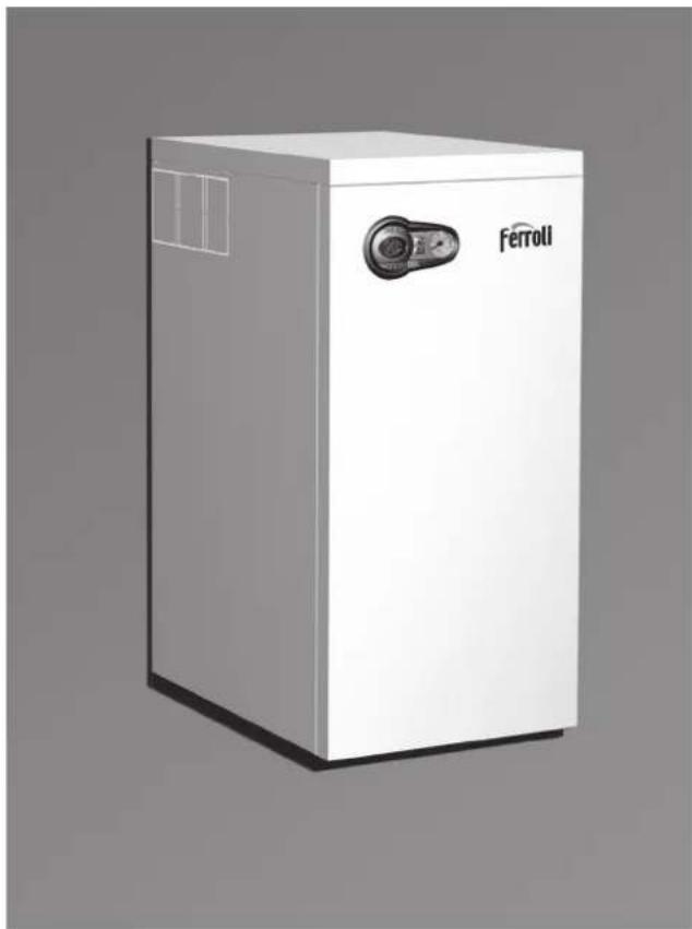
Bluehelix B 35 - Central heating boiler FERROLI - Free user manual and instructions
Find the device manual for free Bluehelix B 35 FERROLI in PDF.

| Product type | Condensing gas boiler |
| Brand | Ferroli |
| Model | Bluehelix B 35 |
| Category | Central heating boiler with integrated domestic hot water production |
| Empty weight | 50 kg |
| Power supply | 230 V / 50 Hz |
| Maximum thermal power heating (80/60°C) | 31.4 kW |
| Minimum thermal power heating (80/60°C) | 6.6 kW |
| Maximum thermal power heating (50/30°C) | 34.0 kW |
| Efficiency at 30% load | 109.8 % |
| NOx emission class | 5 |
| Maximum heating operating pressure | 3 bar |
| Heating circuit water capacity | 4.6 litres |
| Expansion vessel capacity | 10 litres |
| Protection rating | IP X5D |
| Appliance type | C13-C23-C33-C43-C53-C63-C83-B23-B33 |
| Gas | G20 (natural) or G31 (LPG) - adaptable via kit |
| Main functions | Heating and domestic hot water production, summer/winter modes, adaptive temperature, energy saving (Eco/Comfort) |
| Maintenance | Annual inspection by a qualified professional: check safety devices, clean burner and heat exchanger, bleed air, etc. |
| Safety | Antifreeze system, overheat protection, flue safety, fan safety, etc. |
| Spare parts and repairability | Maintenance reserved for a qualified professional; use only original parts. Gas conversion kit available. |
Frequently Asked Questions - Bluehelix B 35 FERROLI
User questions about Bluehelix B 35 FERROLI
0 question about this device. Answer the ones you know or ask your own.
Ask a new question about this device
Download the instructions for your Central heating boiler in PDF format for free! Find your manual Bluehelix B 35 - FERROLI and take your electronic device back in hand. On this page are published all the documents necessary for the use of your device. Bluehelix B 35 by FERROLI.
USER MANUAL Bluehelix B 35 FERROLI
cod. 3541H223 - Rev. 00 - 11/2018
C E
IT - ISTRUZIONE PER L'uso L'INSTALLAZIONE E LA MANUTENZIONE
ES - INSTRUCCIONES DE USO, INSTALLACION Y MANTENIMIENTO
TR - KULLANMA, KURULUM VE BAKIM TALIMATLARI
EN - INSTRUCTIONS FOR USE, INSTALLATION AND MAINTENANCE
FR - INSTRUCTIONS D'UTILISATION, D'INSTALLATION ET D'ENTRETIEN
RU - PYKOBODCTBO NO 3KCNJYATAUH, MOHTAXU IN TEXOBCLJXJBAHIO
UK - IHCTPYKU 3 EKCNIYATAUH, MOHTAXU TA OBCNJYROBYAHN
IT
1.AVVERTENZE GENERALI
Sirkulator yuk / basinc kayiplani
H [m H2O]
sek. 31 - Sirkulator yuk / basinç kayiplari BLUEHELIX B 35
A = Kombi yuk kayiplani - B = Min. sirkulator hizi - C = Maks. Sirkulator hizi

- Carefully read and follow the instructions contained in this instruction booklet.
After boiler installation, inform the user regarding its operation and give him this manual, which is an integral and essential part of the product and must be kept with care for future reference. - Installation and maintenance must be carried out by professionally qualified personnel, in compliance with the current regulations and according to the manufacturer's instructions. Do not carry out any operation on the sealed control parts.
- Incorrect installation or inadequate maintenance can result in damage or injury. The Manufacturer declines any liability for damage due to errors in installation and use, or failure to follow the instructions.
- Before carrying out any cleaning or maintenance operation, disconnect the unit from the electrical power supply using the switch and/or the special cut-off devices.
- In case of a fault and/or poor operation, deactivate the unit and do not try to repair it or directly intervene. Contact professionally qualified personnel. Any repair/replacement of the products must only be carried out by qualified personnel using original replacement parts. Failure to comply with the above could affect the safety of the unit.
- This unit must only be used for its intended purpose. Any other use is deemed improper and therefore hazardous.
- The packing materials are potentially hazardous and must not be left reach of children.
- The unit must not be used by people (including children) with limited physical, sensory or mental abilities or without experience and knowledge of it, unless instructed or supervised in its use by someone responsible for their safety.
- The unit and its accessories must be appropriately disposed of, in compliance with the current regulations.
- The images given in this manual are a simplified representation of the product. In this representation there may be slight and insignificant differences with respect to the product supplied.
2. OPERATING INSTRUCTIONS
2.1 Introduction
Dear Customer,
BLUEHELIX B 35 is a high-efficiency, low emissions premix condensing heat generator with heat exchanger in steel and incorporated DHW production, running on natural gas or LPG and equipped with a microprocessor control system.
The sealed chamber unit is suitable for indoor installation or outdoors in a partially protected place (according to EN 297/A6) with temperatures to -5^ (-15^ with optional antifreeze kit).

The boiler is arranged for connection to an external hot water tank (optional). In this manual, all the functions regarding DHW production are active only with the optional hot water tank connected as indicated in sec. 3.3

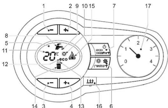
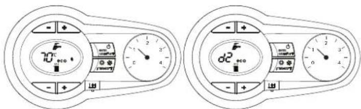
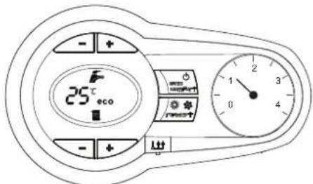
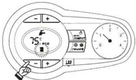
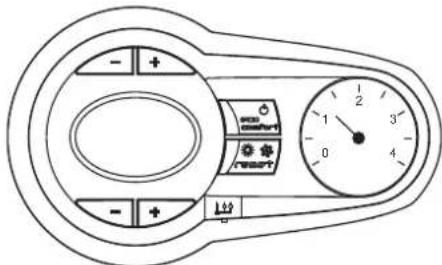
2.2 Control panel
fig.1 - Control panel
Panel - legend fig. 1
"Sliding Temperature" Menu - Summer/Winter mode selection - Reset button
1 DHW temperature setting decrease button
2 DHW temperature setting increase button
3 Heating system temperature setting decrease button
4 Heating system temperature setting increase button
5 Display
7 Unit On/Off - Economy/Comfort mode selection button
8 DHW symbol
9 DHW mode
10 Summer mode
11 Multifunction (flashing during exchanger protection function)
12 Eco (Economy) mode
13 Heating
14 Heating symbol
15 Burner lit and actual power level (flashing during flame protection function)
16 Service Tool connection
17 Water gauge
Indication during operation
Heating
A heating demand (generated by the Room Thermostat or Remote Timer Control) is indicated by flashing of the hot air above the radiator on the display.
The display (detail 11 - fig. 1) shows the actual heating delivery temperature and, during heating standby time, the message "d2".
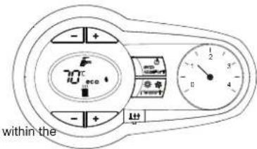
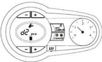
fig.2
Domestic hot water (DHW)
A DHW demand (generated by drawing hot water) is indicated by flashing of the hot water under the tap on the display.
The display (detail 11 - fig. 1) displays the actual DHW outlet temperature and, during DHW standby time, the message "d1".
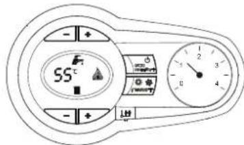
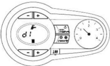
fig. 3
Fault
In case of a fault (see cap. 4.4) the display shows the fault code (detail 11 - fig. 1) and, during safety standby times, the messages "d3" and "d4".
2.3 Connection to the power supply, switching on and off
Boiler not electrically powered
fig. 4 - Boiler not electrically powered

To avoid damage caused by freezing during long idle periods in winter, it is advisable to drain all the water from the boiler.
Boiler electrically powered
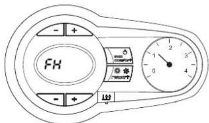
Switch on the power to the boiler.

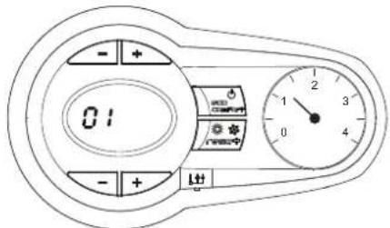
fig. 5 - Switching on / Software version

fig. 6 - Venting cycle
During the first 5 seconds the display also shows the card software version
- For the following 300 seconds the display shows FH which identifies the heating system air venting cycle.
- Open the gas cock ahead of the boiler
- When the message FH disappears, the boiler is ready to operate whenever domestic hot water is drawn or in case of a room thermostat demand
Switching the boiler off and on
Press the on/off button (detail 7 - fig. 1) for 5 seconds.
fig. 7 - Switching the boiler off
When the boiler is switched off, the electronic board is still powered. Domestic hot water and heating are disabled. The antifreeze system remains activated. To switch the boiler on, press the on/off button (detail 7 fig. 1) again for 5 seconds.
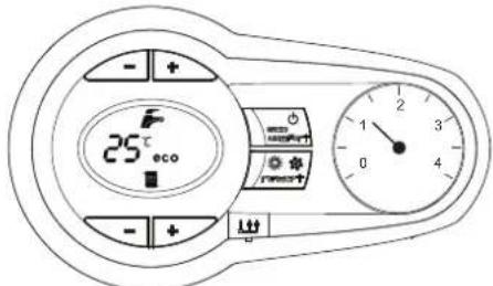
fig.8
The boiler will be immediately ready to operate whenever domestic hot water is drawn or in case of a room thermostat demand.

The antifreeze system does not work when the power and/or gas to the unit are turned off. To avoid damage caused by freezing during long shutdowns in winter, it is advisable to drain all water from the boiler, the DHW circuit and the heating system water; or drain just the DHW circuit and add a suitable anti-freeze to the heating system, as prescribed in sec. 3.3.
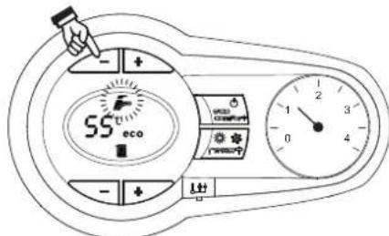
2.4 Adjustments
Summer/Winter Swithchover
Press the summer/winter button (detail 6 - fig. 1) for 2 seconds.
The display activates the Summer symbol (detail 10 - fig. 1): the boiler will only deliver domestic hot water. The antifreeze system remains activated.
To deactivate the Summer mode, press the summer/winter button (detail 6 - fig. 1) again for 2 seconds.
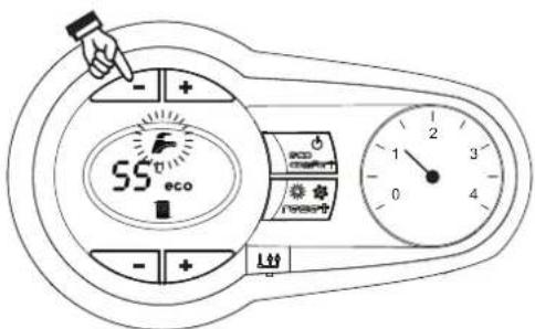
Heating temperature adjustment
Use the heating buttons (details 3 and 4 - fig. 1) to adjust the temperature from a min. of 20^ to a max. of 80^ .
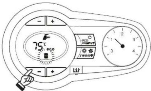
fig.9
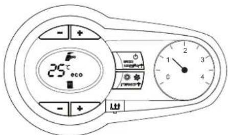
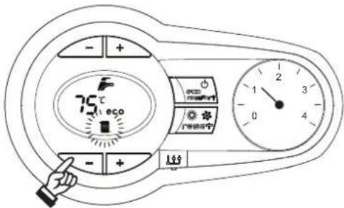
DHW temperature adjustment
Use the DHW buttons (details 1 and 2 - fig. 1) to adjust the temperature from a minimum of 10^ to a maximum of 65^ .
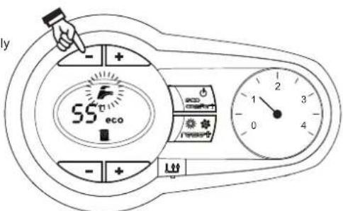
automatically
fig. 10
Room temperature adjustment (with optional room thermostat)
Using the room thermostat, set the temperature required in the rooms. If the room thermostat is not installed, the boiler will keep the system at the set system delivery setpoint temperature.
Room temperature adjustment (with optional remote timer control)
Using the remote timer control, set the required temperature in the rooms. The boiler will adjust the system water according to the required room temperature. For operation with remote timer control, please refer to the relevant instruction manual.
Hot water tank exclusion (economy)
Hot water tank temperature maintaining/heating can be excluded by the user. If excluded, domestic hot water will not be delivered.
The hot water tank can be deactivated by the user (ECO mode) by pressing the ECO/COMFORT button (detail 7 - fig. 1). In ECO mode the display activates the ECO symbol (detail 12 - fig. 1). To activate COMFORT mode, press the ECO/COMFORT button (detail 7 - fig. 1) again.
Sliding Temperature
When the optional external probe is installed, the boiler adjustment system works with "Sliding Temperature". In this mode, the temperature of the heating system is controlled according to the outside weather conditions, to ensure high comfort and energy saving throughout the year. In particular, the system delivery temperature is decreased as the outside temperature increases, according to a specific "compensation curve".
With Sliding Temperature adjustment, the temperature set with the heating buttons (detail 3 - fig. 1) becomes the maximum system delivery temperature. It is advisable to set a maximum value to allow system adjustment throughout its useful operating range.
The boiler must be adjusted at the time of installation by qualified personnel. Possible adjustments can in any case be made by the user to improve comfort.
Compensation curve and curve offset
Press the reset button (detail 6 - fig. 1) for 5 seconds to access the "Sliding temperature" menu; the display shows "CU" flashing.
Use the DHW buttons (detail 1 - fig. 1) to adjust the curve from 1 to 10 according to the characteristic. By setting the curve to 0, sliding temperature adjustment is disabled.
Press the heating buttons (detail 3 - fig. 1) to access parallel curve offset; the display shows "OF" flashing. Use the DHW buttons (detail 1 - fig. 1) to adjust the parallel curve offset according to the characteristic (fig. 11).
Press the reset button (detail 6 - fig. 1) again for 5 seconds to exit the "Sliding Temperature" menu.
If the room temperature is lower than the required value, it is advisable to set a higher order curve and vice versa. Proceed by increasing or decreasing in steps of one and check the result in the room.
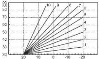
OFFSET = 20 OFFSET = 40
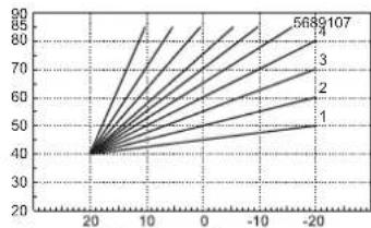
fig. 11 - Example of compensation parallel curve offset
Adjustments from Remote Timer Control

If the Remote Timer Control (optional) is connected to the boiler, the above adjustments are managed according to that given in table 1.
Table.1
| Heating temperature setting | Adjustment can be made from the Remote Timer Control menu and the boiler control panel. |
| DHW temperature adjustment | Adjustment can be made from the Remote Timer Control menu and the boiler control panel. |
| Summer/Winter Swithover | Summer mode has priority over a possible Remote Timer Control heating demand. |
| Eco/Comfort selection | On disabling DHW from the Remote Timer Control menu, the boiler selects the Economy mode. In this condition, the eco/comfort button (detail 7 - fig. 1) on the boiler panel is disabled. |
| On enabling DHW from the Remote Timer Control menu, the boiler selects the Comfort mode. In this condition it is possible select one of the two modes with the eco/comfort button (detail 7 - fig. 1) on the boiler panel. | |
| Sliding Temperature | Both the Remote Timer Control and the boiler card manage Sliding Temperature adjustment: the boiler card Sliding Temperature has priority. |
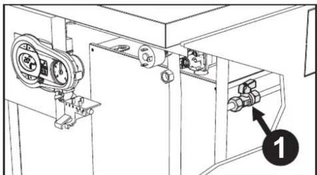
Plumbing system pressure adjustment
The filling pressure read on the boiler water gauge with the system cold must be approx 1.0 bar. If the system pressure fails to values below minimum, the boiler stops and fault F37 is displayed. Operate the filling cock, if connected to the water supply system (detail 1 fig. 12 and bring it to the initial value. Always turn it off it afterwards.
Once the system pressure is restored, the boiler will activate the 300-second air venting cycle indicated on the display by FH.
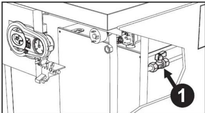
fig. 12 - System filling cock
3. INSTALLATION
3.1 General Instructions
BOILER INSTALLATION MUST ONLY BE PERFORMED BY QUALIFIED PERSONNEL, IN ACCORDANCE WITH ALL THE INSTRUCTIONS GIVEN IN THIS TECHNICAL MANUAL, THE PROVISIONS OF CURRENT LAW, THE PRESCRIPTIONS OF NATIONAL AND LOCAL STANDARDS AND THE RULES OF PROPER WORKMANSHIP.
3.2 Place of installation
The combustion circuit is sealed with respect to the place of installation room, therefore the unit can be installed in any room. However, the place of installation must be adequately ventilated to prevent the creation of dangerous conditions in case of even small gas leaks. This safety regulation is laid down by EEC Directive no. 2009/142 for all gas units, including those with sealed chamber.
The unit is suitable for indoor installation.
The place of installation must be dry, not exposed to rain, snow or frost, and free of flammable dusts, objects and materials and corrosive gases.

If the unit is enclosed in a cabinet or mounted alongside, a space must be provided for removing the casing and for normal maintenance operations.
3.3 Plumbing connections
Important
The safety valve outlet must be connected to a funnel or collection pipe to prevent water spurting onto the floor in case of overpressure in the heating circuit. Otherwise, if the discharge valve cuts in and floods the room, the boiler manufacturer cannot be held liable.
Before installation, carefully wash all the pipes of the system to remove any residues or impurities that could affect proper operation of the unit.
In case of replacement of generators in existing installations, the system must be completely emptied and cleaned of any sludge and pollutants. For that purpose only use suitable guaranteed products for heating systems (see next section), that do not harm metals, plastics or rubber. The manufacturer declines any liability for damage caused to the generator by failure to properly clean the system.
Carry out the relevant connections according to the diagram in fig. 13 and the symbols on the unit.
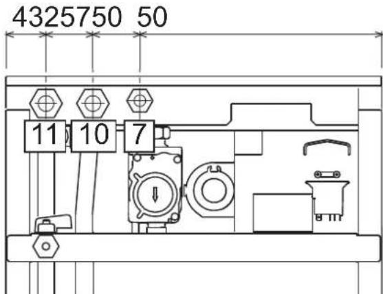
fig. 13 - Plumbing connections
7 Gas inlet-1/2
10 System delivery - 3/4"
11 System return -3/4
Antifreeze system, antifreeze fluids, additives and inhibitors
When necessary, antifreeze fluids, additives and inhibitors can be used only if the manufacturer of such fluids or additives guarantees that they are suitable and do not cause damage to the exchanger or other components and/or materials of the boiler and system. Do not use generic antifreeze fluids, additives or inhibitors that are not specific for use in heating systems and compatible with the materials of the boiler and system.
Water system characteristics
In the presence of water harder than 25^ (1°F = 10ppm CaCO₃), use suitably treated water in order to avoid possible scaling in the boiler.
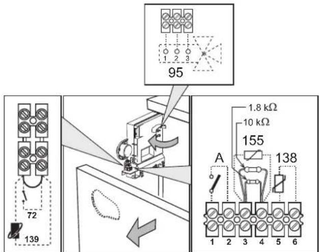
Connection to a storage tank for domestic hot water production
The unit's electronic board is arranged for managing an external storage tank for domestic hot water production. Make the plumbing connections according to the diagram of fig. 14. Make the electrical connections as shown on the wiring diagram in fig. 32. It is necessary to use the kit code 1KWMA11W. At the next lighting, the boiler's control system recognises the presence of the hot water tank probe and is automatically configures the DHW function, activating the display and relevant controls.
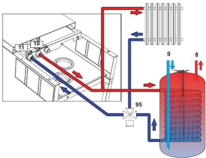
fig. 14 - Diagram of connection to an external hot water tank
8 Domestic hot water outlet
9 Cold water inlet
10 System delivery
11 System return
95 Diverter valve
3.4 Gas connection
Before making the connection, ensure that the unit is arranged for operation with the type of fuel available.
The gas must be connected to the relevant connection (see fig. 13) in conformity with the current standards, using a rigid metal pipe or a continuous surface flexible s/steel tube and installing a gas cock between the system and boiler. Make sure all the gas connections are tight.
3.5 Electrical connections
The unit must be connected to an efficient earthing system in accordance with current safety standards. Have the efficiency and suitability of the earthing system checked by professionally qualified personnel; the Manufacturer declines any liability for damage caused by failure to earth the system.
The boiler is prewired and provided with a "Y" type cable (without plug) for connection to the electric line. The connections to the grid must be made with a permanent connection and equipped with a bipolar switch whose contacts have a minimum opening of at least 3mm , interposing fuses of max. 3A between the boiler and the line. Make sure to respect the polarities (LINE: brown wire / NEUTRAL: blue wire / EARTH: yellow-green wire) in the connections to the electric line.
The unit's power cable must not be replaced by the user. If the cable gets damaged, switch off the unit and have it replaced only by professionally qualified personnel. In case of replacement, use exclusively "HAR H05 VV-F" 3x0.75 mm2 cable with maximum ext. diameter of 8 mm.
Room thermostat (optional)
IMPORTANT: THE ROOM THERMOSTAT MUST HAVE VOLTAGE-FREE CONTACTS. CONNECTING 230V TO THE ROOM THERMOSTAT TERMINALS WILL PERMANENTLY DAMAGE THE PCB.
When connecting a time control or timer, do not take the power supply for such devices from their cutoff contacts. Their power supply must be taken with a direct connection from the mains or with batteries, depending on the type of device.
Accessing the electrical terminal block
The electrical terminal block (fig. 15) can be accessed after removing the front panel (*** 'Opening the front panel' on page 51^** ). The layout of the terminals for the various connections is also given in the wiring diagram in fig. 32.
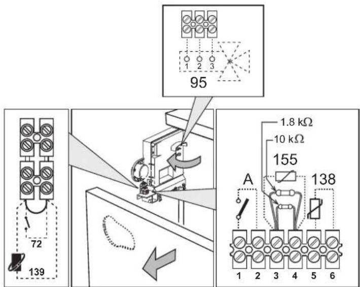
fig. 15 - Accessing the terminal block
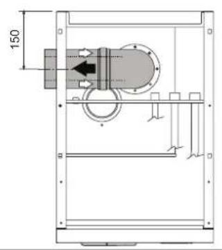
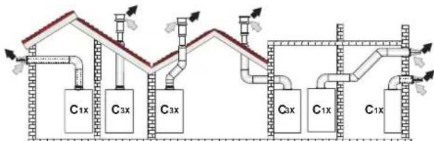
3.6 Fume ducts
Important
The unit is a "C type" with sealed chamber and forced draught; the air inlet and fume outlet must be connected to one of the following extraction/suction systems. Before installation, check and carefully follow the instructions. Also, comply with the provisions on the positioning of wall and/or roof terminals and the minimum distances from windows, walls, ventilation openings, etc.
For the possible outlet configurations and installation distances, refer to table 7 and table 8.
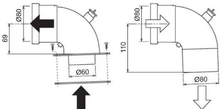
Connection with coaxial pipes
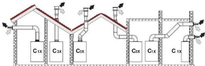
fig. 16 - Examples of connection with coaxial pipes ( = Air / = Figs)
Table.2 - Typology
| Type Description | |
| C1X | Wall horizontal exhaust and inlet |
| C3X | Roof vertical exhaust and inlet |
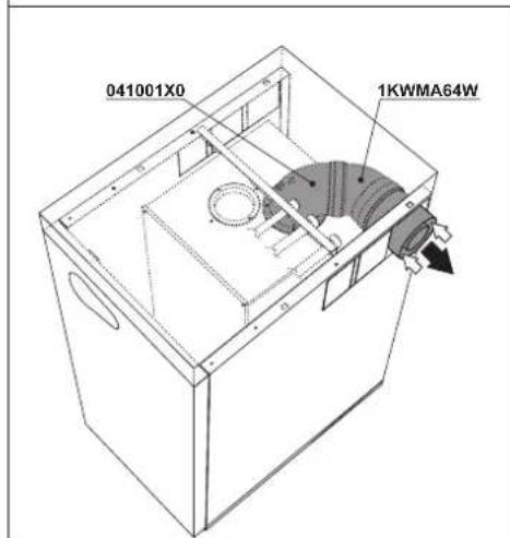
For coaxial connection, fit the unit with one of the following starting accessories. Any horizontal sections of the fume exhaust must be kept sloping slightly towards the boiler, to prevent possible condensate from flowing back towards the outside and causing dripping.
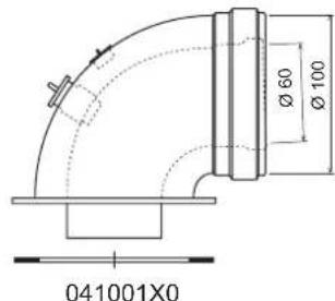
fig. 17 Starting accessories for coaxial ducts
Table. 3 - Max. length of coaxial pipes
| Coaxial 60/100 Coaxial 80/125 | ||
| Max. permissible length (horizontal) 7 m | 28 m | |
| Max. permissible length (vertical) 8 m | ||
| Reduction factor 90° bend 1 m 0.5 m | ||
| Reduction factor 45° bend 0.5 m 0.25 m | ||
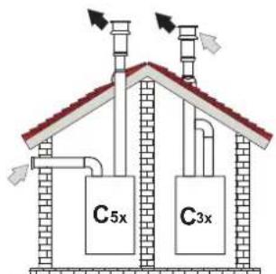
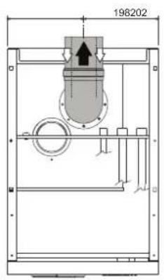
Connection with separate pipes
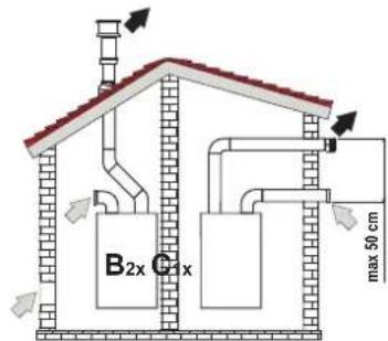
fig.18 - Examples of connection with separate pipes Air/ = Frieses
Table. 4 - Typology
| Type Description | |
| C1X | Wall horizontal exhaust and intake. The inlet/outlet terminals must be concentric or close enough to be undergo similar wind conditions (within 50 cm) |
| C3X | Roof vertical exhaust and intake. Inlet/outlet terminals like for C12 |
| C5X | Wall or roof exhaust and intake separate or in any case in areas with different pressures. The exhaust and intake must not be positioned on opposite walls. |
| C6X | Intake and exhaust with separately certified pipes (EN 1856/1) |
| B2X | Intake from installation room and wall or roof exhaustIMPORTANT - THE ROOM MUST BE PROVIDED WITH APPROPRIATE VENTILATION |
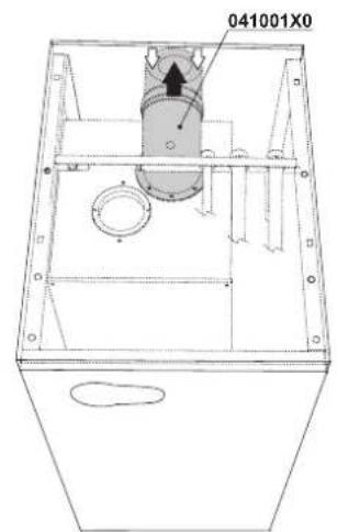
For the connection of separate ducts, fit the unit with the following starting accessory (Air = - Fumes =)

041065X0
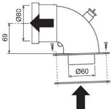
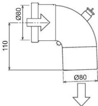
fig. 19 - Starting accessory for separate ducts
Before installation, make sure the maximum permissible length has not been exceeded, by means of a simple calculation:
- Completely establish the layout of the system of split flues, including accessories and outlet terminals.
- Consult the table 6 and identify the losses in m eq (equivalent metres) of every component, according to the installation position.
- Check that the sum total of losses is less than or equal to the maximum permissible length in table 5.
Table. 5 - Maximum length of separate ducts
| Max. permissible length | 80 mEq |
Table. 6 - Accessories
| Losses in \(m_{\text{eq}}\) | |||||
| Air inlet | Fume exhaust | ||||
| Vertical Horizontal | |||||
| ∅ 60 | PIPE | 1 m M/F 1KWMA83W 1.0 1.6 | 2.0 | ||
| BEND | 45° M/F 1KWMA65W 1.2 1.8 | ||||
| 90° M/F 1KWMA01W 1.5 2.0 | |||||
| PIPE SECTION | with test point 1KWMA70W 0.5 | 0.3 | |||
| TERMINAL | air, wall | 1KWMA85A 2.0 | - | ||
| fumes, wall with antiwind | 1KWMA86A | - | 5.0 | ||
| FLUE | Split air/fumes 80/80 | 010027X0 | - | 12.0 | |
| Fume outlet only Ø80 010026 | x0 + 1KWMA86U | - | 4.0 | ||
| ∅ 60 | PIPE | 1 m M/F 1KWMA89W | 6.0 | ||
| BEND | 90° M/F 1KWMA88W | 4.5 | |||
| REDUCTION | 80/60 | 041050X0 | 5.0 | ||
| TERMINAL | fumes, wall with antiwind | 1KWMA90A | 7.0 | ||
| ATTENTION: CONSIDER THE HIGH PRESSURE LOSSES OF Ø60 ACCESSORIES;USE THEM ONLY IF NECESSARY AND AT THE LAST FUME EXHAUST SECTION. | |||||
Configuration of flues
Air inlet = Fume outlet
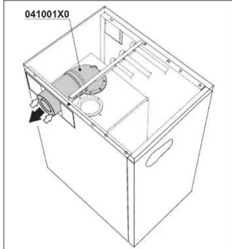
Table. 7 - Connection with coaxial pipes
Left outlets
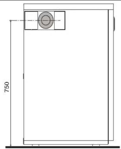
Rear outlets
Right outlets
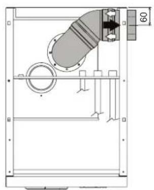
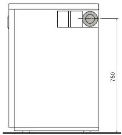
Table. 8 - Connection with separate pipes
| Left outlets | ||
| 85148 | 750 | |
| Rear outlets | ||
| 11785198 | 11719885 | |
| Right outlets | ||
| 56 105 | 750 | |
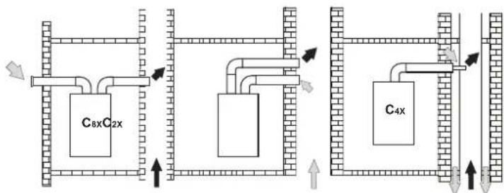
Connection to collective flues
fig. 20 - Examples of connection to flues (Air / = Flues)
Table. 9 - Typology
| Type Description | |
| C2X | Intake and exhaust in common flue (intake and exhaust in same flue) |
| C4X | Intake and exhaust in common and separate flues, but undergoing similar wind conditions |
| C8X | Exhaust in single or common flue and wall intake |
| B3X | Intake from installation room by means of concentric duct (that encloses the exhaust) and exhaust in common flue with natural draught IMPORTANT - THE ROOM MUST BE PROVIDED WITH APPROPRIATE VENTILATION |
If the boiler is to be connected BLUEHELIX B 35 to a collective flue or a single flue with natural draught, the flue or chimney must be expressly designed by professionally qualified technical personnel in conformity with the current regulations and be suitable for sealed chamber units equipped with fan.
3.7 Condensate drain connection
The boiler has an internal trap for draining condensate. Fit the inspection union A and the hose B, pressing it in. Fill the trap with approx. 0.5 l. of water and connect the hose to the disposal system.

ATTENTION: The unit must never be operated with the trap empty!
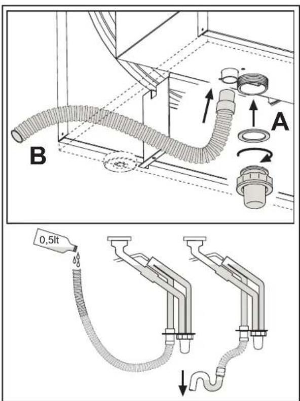
fig.21-Condensate outlet connection
4. SERVICE AND MAINTENANCE
4.1 Adjustments
Gas conversion
The unit can operate on Natural Gas or LPG and is factory-set for use with one of these two gases, as clearly shown on the packing and on the data plate. Whenever a different gas to that for which the unit is arranged has to be used, a conversion kit will be required, proceeding as follows:
- Disconnect the boiler power supply and close the gas cock.
- Remove the front panel and the panel of the sealed chamber (see fig. 22).
- Undo the screw and rotate the control panel (see fig. 22).
-
Unscrew the ring C and E and remove the gas valve (see fig. 23).
-
Replace nozzle B inserted in the gas pipe with that contained in the conversion kit, interposing seal D (see fig. 23).
-
Reassemble the valve and check the tightness of the connection.
- Apply the label, contained in the conversion kit, near the data plate.
- Refit the front panel.
-
Switch the boiler power on and open the gas cock.
10.Modify the parameter for the type of gas: -
put the boiler in standby mode
- press the DHW buttons details 1 and 2 - fig. 1 for 10 seconds: the display shows "b01" flashing.
- press the DHW buttons details 1 or 2 - fig. 1 to set parameter 00 (for operation with natural gas) or 01 (for operation with LPG).
press the heating ^+ button (detail 4 - fig.1) until "b06" flashes on the display. - press the DHW buttons (details 1 or 2 - fig. 1) to set parameter 55 (for operation with natural gas) or 70 (for operation with LPG).
-
press the DHW buttons details 1 and 2 - fig. 1 for 10 seconds.
the boiler will return to standby mode -
Using a combustion analyser connected to the boiler fume outlet, check that the CO_2 content in the fumes, with the boiler operating at max. and min. output, matches that given in the technical data table for the corresponding type of gas.
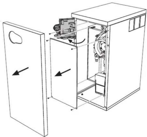
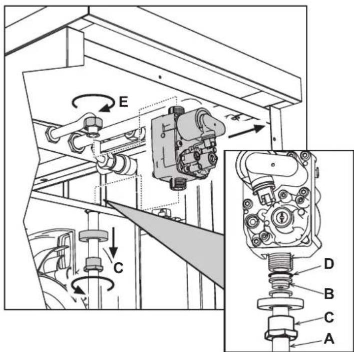
fig.22
fig.23
TEST mode activation
Press the heating buttons (details 3 and 4 - fig. 1) together for 5 seconds to activate the TEST mode. The boiler lights at the maximum heating power set as described in the following section.
The heating and DHW symbols (fig. 24) flash on the display; the heating power will appear alongside.
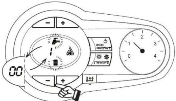
fig.24 - TEST mode (heating power = 100%
Press the heating buttons (details 3 and 4 - fig. 1) to increase or decrease the power (Min. = 0%, Max. = 100%).
By pressing the DHW "+" button (detail 1 - fig. 1), boiler output is immediately adjusted to min. (0%) . By pressing the DHW "+" button (detail 2 - fig. 1), boiler output is immediately adjusted to max. (100%) .
If the TEST mode is activated and enough hot water is drawn to activate the DHW mode, the boiler remains in TEST mode but the 3-way valve goes to DHW.
To deactivate the TEST mode, press the heating buttons (details 3 and 4 - fig. 1) together for 5 seconds.
The TEST mode is automatically deactivated in any case after 15 minutes or on stopping of hot water drawing (if enough hot water has been drawn to activate the DHW mode).
Heating power adjustment
To adjust the heating power, switch the boiler to TEST mode (see sec. 4.1). Press the heating buttons fig. 1 (details 3 and 4 -) to increase or decrease the power (min. = 00 - max. = 100). Press the RESET button within 5 seconds and the max. power will remain that just set. Exit TEST mode (see sec. 4.1).
4.2 Startup
Before lighting the boiler
-
Check the seal of the gas system.
-
Check correct prefilling of the expansion tank.
-
Fill the water system and make sure all air contained in the boiler and the system has been vented.
Make sure there are no water leaks in the system, DHW circuits, connections or boiler.
- Check correct connection of the electrical system and efficiency of the earthing system.
Make sure the gas pressure for heating is that required.
- Make sure there are no flammable liquids or materials in the immediate vicinity of the boiler
Checks during operation
- Switch the unit on.
- Check the tightness of the fuel circuit and water systems.
- Check the efficiency of the flue and air/fume ducts while the boiler is working.
- Check the correct tightness and efficiency of the condensate removal system and trap.
Make sure the water is circulating properly between the boiler and systems. - Make sure the gas valve modulates correctly in heating and domestic hot water production.
- Check proper lighting of the boiler by turning it on and off several times with the room thermostat or remote control.
Make sure the fuel consumption indicated on the meter matches that given in the technical data table on cap. 5. - Make sure that with no heating demand the burner correctly lights on opening a hot water tap. Check that the heating circulating pump stops on opening a hot water tap during heating operation and there is a regular production of hot water.
- Check correct programming of the parameters and carry out any required customisation (compensation curve, power, temperatures, etc.).
4.3 Maintenance
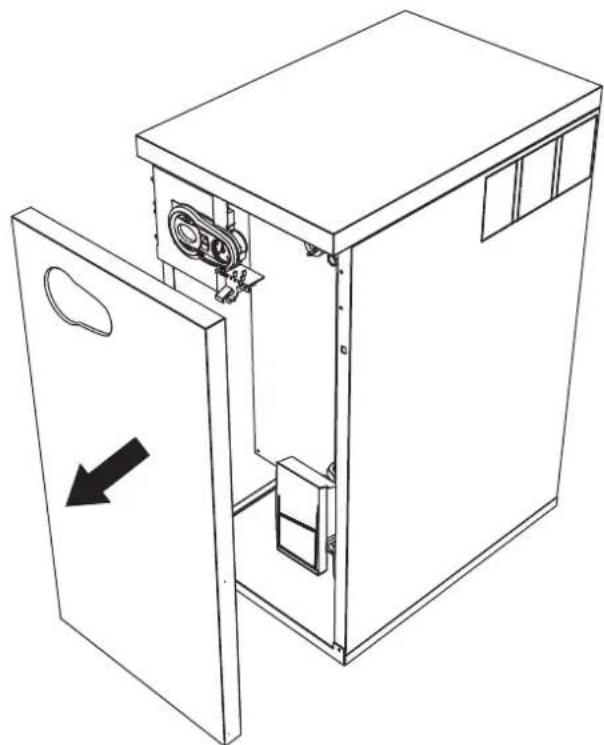
Opening the front panel
To open the boiler casing pull the panel outwards and release it (see fig. 25).
Before carrying out any operation inside the boiler, disconnect the power and close the gas cock upstream.
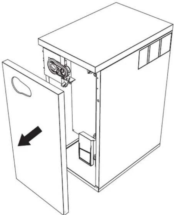
fig.25-Front panel opening
Periodical check
To ensure proper operation of the unit over time, have qualified personnel carry out a yearly inspection, providing for the following checks:
- The control and safety devices (gas valve, flow meter, thermostats, etc.) must function correctly
The fume exhaust circuit must be perfectly efficient
The sealed chamber must be tight
The air-fume end piece and ducts must be free of obstructions and leaks - The burner and exchanger must be clean and free of deposits. For possible cleaning do not use chemical products or wire brushes
The electrode must be properly positioned and free of scale
The gas and water systems must be tight. - The water pressure in the cold water system must be about 1 bar; otherwise, bring it to that value
The circulating pump must not be blocked.
The expansion tank must be filled. - The gas flow and pressure must correspond to that given in the respective tables
The condensate evacuation system must be efficient with no leakage or obstructions
The trap must be full of water.
4.4 Troubleshooting
Diagnostics
In case of operation faults or problems, the display flashes and the fault identification code appears.
There are faults that cause permanent shutdown (marked with the letter "A"): to restore operation just press the reset button (detail 6 -fig. 1) for 1 second or RESET on the optional remote timer control if installed; if the boiler fails to start, it is necessary to firstly eliminate the fault.
Faults marked with the letter "F" cause temporary shutdowns that are automatically reset as soon as the value returns within the boiler's normal working range.
Table of faults
Table. 10 - List of faults
| Fault code | Fault Possible cause Cure | ||
| A01 | No burner ignition | No gas | Check the regular gas flow to the boiler and that the air has been eliminated from the pipes |
| Ignition/detection electrode fault | Check the wiring of the electrode and that it is correctly positioned and free of any deposits | ||
| Faulty gas valve | Check the gas valve and replace it if necessary | ||
| Insufficient gas supply pressure Check the gas supply pressure | |||
| Trap blocked | Check the trap and clean it if necessary | ||
| A02 | Flame present signal with burner off | Electrode fault Check the ionisation electrode wiring | |
| Card fault Check the card | |||
| A03 | Overtemperature protection activation | Heating sensor damaged | Check the correct positioning and operation of the heating sensor |
| No water circulation in the system Check the circulating pump | |||
| Air in the system Vent the system | |||
| A04 | Fume extraction duct safety device activation | Fault F07 generated 3 times in the last 24 hours | See fault F07 |
| A05 | Fan protection activated | Fault F15 generated for 1 hour (consecutive) | See fault F15 |
| A06 | No flame after ignition stage (6 times in 4 minutes) | Ionisation electrode fault Check the position of the ionisation electrode and replace it if necessary | |
| Flame unstable Check the burner | |||
| Gas valve Offset fault Check the Offset adjustment at minimum power | |||
| air/fume ducts obstructed | Remove the obstruction from the flue, fume extraction ducts and air inlet and terminals | ||
| Trap blocked | Check the trap and clean it if necessary | ||
| F07 | High fume temperature | The fume probe detects an excessive temperature | Check the exchanger |
| F10 | Delivery sensor 1 fault | Sensor damaged | Check the wiring or replace the sensor |
| Wiring disconnected | |||
| F11 | Return sensor fault | Sensor damaged | Check the wiring or replace the sensor |
| Wiring disconnected | |||
| F12 | DHW sensor fault | Sensor damaged | Check the wiring or replace the sensor |
| Wiring disconnected | |||
| F13 | Fume probe fault | Probe damaged | Check the wiring or replace the fume probe |
| Wiring shorted | |||
| Wiring disconnected | |||
| F14 | Delivery sensor 2 fault | Sensor damaged | Check the wiring or replace the sensor |
| Wiring disconnected | |||
| F15 | Fan fault | No 230V power supply | Check the 8-pin connector wiring |
| Tachometric signal interrupted | Check the 8-pin connector wiring | ||
| Fan damaged | Check the fan | ||
| F34 | Supply voltage under 170V | Electric mains trouble Check the electrical system | |
| F35 | Faulty mains frequency | Electric mains trouble Check the electrical system | |
| F37 | Incorrect system water pressure | Pressure too low | Fill the system |
| Water pressure switch damaged or not connected | Check the sensor | ||
| F39 | External probe fault | Probe damaged or wiring shorted | Check the wiring or replace the sensor |
| Probe disconnected after activating the sliding temperature | Reconnect the external probe or disable the sliding temperature | ||
| A41 A44 | Sensor positioning | Heating sensor detached from pipe | Check the correct positioning and operation of the heating sensor |
| A42 | Heating sensor fault | Sensor damaged | Replace the sensor |
| Fault code | Fault Possible cause Cure | ||
| F43 | Exchanger protection activa-tion. | No system \( H_2O \)circulation | Check the circulating pump |
| Air in the system Vent the system | |||
| F52 | Heating sensor fault | Sensor damaged | Replace the sensor |
| A61 | Controller ABM03 fault | Controller ABM03 internal error | Check the earth connection and replace the controller if necessary. |
| A62 | No communication between controller and gas valve | Controller not connected | Connect the controller to the gas valve |
| Valve damaged | Replace the valve | ||
| A63 | Controller ABM03 fault | Controller ABM03 internal error | Check the earth connection and replace the controller if necessary. |
| F64 | |||
| A65 | |||
| F66 | |||
| A23 | Card parameter fault | Wrong card parameter setting | Check the card parameter and modify it if necessary. |
| A24 | |||
| F20 | |||
| F21 | |||
| A26 | |||
| F40 | |||
| F47 |
5. TECHNICAL DATA AND CHARACTERISTICS
Table. 11 -Key of figures cap. 5
| 7 Gas inlet | 138 | External probe (optional) |
| 10 System delivery | 139 | Remote timer control (optional) |
| 11 System return | 145 | Pressure gauge |
| 14 System safety valve | 154 | Condensate drain pipe |
| 16 Fan | 155 | Hot water tank temperature probe (optional) |
| 32 Heating circulating pump | 186 | Return sensor |
| 36 Automatic air vent | 191 | Fume temperature sensor |
| 44 Gas valve | 193 | Trap |
| 56 Expansion tank | 241 | Automatic bypass |
| 72 Room thermostat (optional) | 256 | Modulating heating circulating pump signal |
| 74 System filling cock | 275 | Heating system drain cock |
| 81 Ionisation/ignition electrode | 278 | Double sensor (Safety + Heating) |
| 95 Diverter valve (optional) | 350 | Fan/Burner assembly |
| 114 Water pressure switch | A | ON/OFF switch (configurable) |
5.1 General view and main components
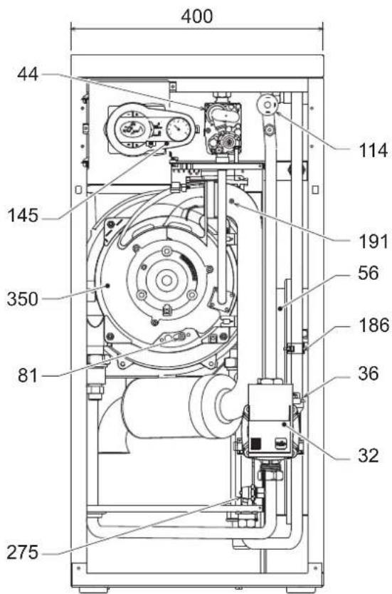
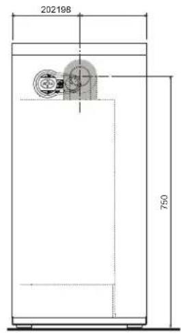
fig. 26 - Front view
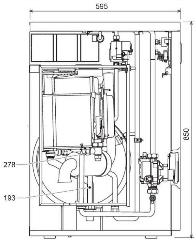
fig.27 - Side view
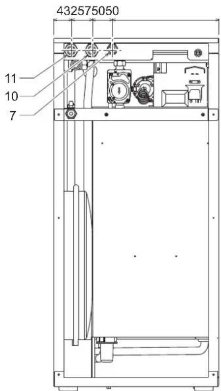
fig.28 - Rear view
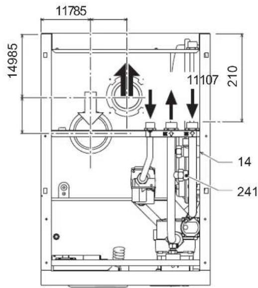
fig.29 - Top view (AIR INLET = FUME OUTLET = )
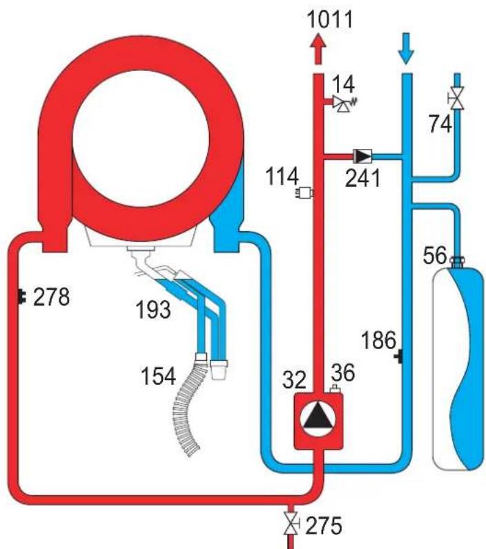
5.2 Water circuit
fig. 30 - Water circuit
5.3 Diagrams
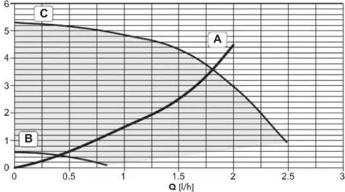
Circulating pump head / pressure losses
H [m H2O]

fig. 31 - Circulating pump head / Pressure losses BLUEHELIX B 35
A = Boiler pressure losses - B = Circulating pump min. speed - C = Circulating pump max. speed

For correct modulation, the speed selector on the pump must be set to III.
5.4 Technical data table
The column on the right gives the abbreviation used on the data plate.
| Data Unit BLUEHELIX B 35 | |||
| Max. heating capacity kW 32.0 (Q) | |||
| Min. heating capacity kW 6.7 (Q) | |||
| Max. Heat Output in heating (80/60°C) kW 31.4 (P) | |||
| Min. Heat Output in heating (80/60°C) kW 6.6 (P) | |||
| Max. Heat Output in heating (50/30°C) kW 34.0 | |||
| Min. Heat Output in heating (50/30°C) kW 7.2 | |||
| Efficiency Pmax (80-60°C) | % | 98.1 | |
| Efficiency Pmin (80-60°C) | % | 97.8 | |
| Efficiency Pmax (50-30°C) | % | 106.1 | |
| Efficiency Pmin (50-30°C) | % | 107.5 | |
| Efficiency 30% | % | 109.8 | |
| Efficiency class Directive 92/42 EEC | - | ★★★★★ | |
| NOx emission class | - | 5 (NOx) | |
| Gas supply pressure G20 | mbar | 20 | |
| Max. gas delivery G20 | \( m^3/h \) | 3.39 | |
| Min. gas delivery G20 | \( m^3/h \) | 0.71 | |
| CO2 max. G20 | % | 9.30 | |
| CO2 min. G20 | % | 8.70 | |
| Gas supply pressure G31 | mbar | 37 | |
| Max. gas delivery G31 | kg/h | 2.49 | |
| Min. gas delivery G31 | kg/h | 0.52 | |
| CO2 max. G31 | % | 10.70 | |
| CO2 min. G31 | % | 9.80 | |
| Max. working pressure in heating | bar | 3 (PMS) | |
| Min. working pressure in heating | bar | 0.8 | |
| Max. heating temperature | °C | 90 | (tmax) |
| Heating water content | litres | 4.6 | |
| Heating expansion tank capacity | litres | 10 | |
| Heating expansion tank prefilling pressure | bar | 0.8 | |
| Protection rating | IP X5D | ||
| Power supply voltage | V/Hz | 230V/50Hz | |
| Electrical power input | W | 109 | |
| Empty weight | kg | 50 | |
| Type of unit | C13-C23-C33-C43-C53-C63-C83-B23-B33 | ||
| PIN CE | 0461CM0988 |
rprodufohe
2222:33
| #rdemrk:### | |||
| #r#n#n#s#r#n#r#r#r#r#r#r#r#r#r#r#r#r#r#r#r#r#r#r#r#r#r#r#r#r#r#r#r#r#r#r#r#r#r#r#r#r#r#r#r#r#r#r#r#r#r#r#r#r#r#r# r# | |||
| #10000000000000000000000000000000000000000000000000000000000000000000000000000000000000000000000000000 | |||
| #2000000000000000000000000000000000000000000000000000000000000000000000000000000000000000000000000000 | #ymol#ni#n#l# | ||
| #200000000000000000000000000000000000000000000000000000000000000000000000000000000000000000000 | #n | k# | 31 |
| #20000000000000000000000000000000000000000000000000000000000000000000000000000000000000000000000 | S□ | % | 94 |
| #sefulthe#doutput | |||
| #s#u#u#u#t#utput#t#t#t#t#t#t#t#t#t#t#t#t#t#t#t#t#t#t#t#t#t#t#t#t#t#t#t#t#t#t#t#t#t#t#t#t#t#t#t#t#t#t#t#t#t#t#t#t#t#t# t(*) | #4 | k# | 31,4 |
| #s#u#u#u#t#utput#t#t#t#t#t#t#t#t#t#t#t#t#t#t#t#t#t#t#t#t#t#t#t#t#t#t#t#t#t#t#t#t#t#t#t#t#t#t#t#t#t#w-t#t#p#t#t#t#t#t#t#t#t#t#t#t#t#t#t#t#t#t#t#t#t#t#t#t#t#t#t#t#t#t#t#t#t#t#t#t#t#t#t#t#t#t#t#t#t#t#t#t#t#t# | #1 | k# | 6,4 |
| #sefullefficienry | |||
| #s#u#u#u#u#t#t#t#t#t#t#t#t#t#t#t#t#t#t#t#t#t#t#t#t#t#t#t#t#t#t#t#t#t#t#t#t#t#t#t#t#t#t#t#t#t#t#t#t#t#t#t#t#t#w-t#t#p#t#t#t#t#t##t#t#t#t#t#t#t#t#t#t#t#t#t#t#t#t#t#t#t#t#t#t#t#t#t#t#t#t#t#t#t#t#t#t#t#t#t#t#t#t#t#t#t#t#t#t#t#t#t#t #(*) | S□ | % | 88,3 |
| #s#u#u#u#u#t#t#t#t#t#t#t#t#t#t#t#t#t#t#t#t#t#t#t#t#t#t#t#t#t#t#t#t#t#t#t#t#t#t#t#t#t#t#t#t#t#t#t# | S□ | % | 98,9 |
| uxili#ryiele@triityconsumption | |||
| #ti#u#u#u#u | elm#x | k# | 0,068 |
| #upart#u | elmin | k# | 0,017 |
| #ist#u#y#u | # | k# | 0,003 |
| #thenitems | |||
| #ti#u#y#u#ti#ssi | #st#y | k# | 0,043 |
| #u#u#u#u#ur#tr#rp#w#r#u#su#pt#u | #ign | k# | 0,000 |
| #u#u#u#u#u#r#ty#u#u#su#pt#u | # | k# | 59 |
| #u#u#u#u#u#w#r#v#u | # | d# | 56 |
| #issu#s#u#u#u#tr#u#u#u#x#u#s | # | mg/k# h | 30 |
Temperature evolutive
3.4 Raccordement gaz
pnc.1-PaHnBynpaBneHnA
YcnoBhble 6o3haeHnHa naHEn ynpaBneHn pnc.1
1 Khonka yEmhSeHnra 3aadaaemOy Tempepatpyb B CNTcTeME TBC
2 Khonka yBeHneHnra 3aadaaemOy Tempepatpyb B CNTcTeME TBC
3 Khonka yEmhSeHnra 3aadaaemOy Tempepatpyb B CNTcTeME OTONHeHn
4 Khonka yBeHneHnra 3aadaaemOy Tempepatpyb B CNTcTeME OTONHeHn
5 DcncIe
6 Khonka "Cbpc" -Bb6op pexima "Jeto"/"3Hma" -MeHo "TnaabaOuaa Tempepatypa"
7 KhoNka BbIbopa peKIMa "3KoHOMuHbI"KOMΦopT - "BKn/BbIKn"KOTna 8 CmB0n TBC
9 CmBON pa6oTb arperata B pexnme TBC
10 Hnkaunna "NeTHn peKm"
11 HnHkaaMnHOFOyHKUHOHaIbHOrOpeKMa(MnraetnpnAKTBHOyHKU 3aunTbTeNIOoMeHHKA)
12 CnMBOJ peKHMa "Eco" (3KOHOMHbH)
13 HdkaupaobarperataBpeKMeOTonneHn
14 CnMBOJ OTONJIENH
15 HnDnkaaia 3aKHeHNO rOpEn K N TeKUeM MoHocTN (Mraet npnakTBHO FyHKuIN 3aunTbI PnAmEH)
16 POnKIOUChHeNc KcpEcdTbAM TExHnueckoro 06CnykBaHn
17 ⅣnpomTp
HdkauaBOBpeMa pa60tkoTna
PexMMOTONJIeHn
O NOctynneHm KOMaHbI bA BKNIOeHHe OTONNEHn (OT KOMHaTHoR TepMOCTa HIN OTy Ta C TeMApOm) npedynpeXdaet MIRAHHe INHdkatoprTaENrOTo BO3dyxHaNc CMBOONoB SaTApEn HaCNnee.
Ha dncnnee (no3.11-pnc.1) BbcBceuBaTc TEmpeaTypaB noDaHouem KOHType CNTeMbI OTONHeHnA, a BO BpEma PEXKMA OXnDAnHn -CNMBON "d2".
pnc.2
Pexn m ropayero BOOCha6xHn
O 3anpoce TBC (BblbBaemom Notpe6neHemrnpaen B0db) coo6aaet MmraHne CMBbora npaeBnDnKpaHOM Ha nCnnee.
Ha dncnnee (no3. 11 - pnc. 1) oto6paKaetc TekyuAa Tempeatypa BOnB b KOnThype ropeo BOOChabxKeHn, TaKae HaTnCb "d" Bv BPem OKnDaHnropee BOnbl.

pnc.3
HemcpabHOCTb
Bcnyae HencnpaHocTn (cm. cap. 4.4) Ha dncnnee oTo6paXaetcKao HeNCnpaHocTn (no3.11-pnc.1) n BO Bpemx OxuDAnH-HaDnCn "d3" n "d4".
2.3 NoknouheK cetn 3neKtpueckoro nTuHnBkIOUeHne HbIKIOUeHne KotoN 6e3 noaun 3neKtpoNTaHn
pnc.4-Koter 6e3 noaun 3neKtponntanu
B cnyuae npoDOnknteHbHO nepepbBa B pa6ote B 3mMHe nepMOdb, YTO6bl H36ekKaTb ONeDEHnHn, peKOMeHdyETcNtB BCIO BOy N3 KOTna.
Koten nodknouehen K cetn 3neKtponntaHna
IpaTe 3NEKTPoNTaHHe Ha KOTen.

pnc.5-BknoeHne/BepnIPO

pnc.6-LuKn cnycka Bo3dyxa
B TeueHHe 5 cekyHn Ha duncnne 6ydt BbICeHuBaTBc BepCn nporpaMMHOro oecneueHH, yCTaHOBHeHHORO B aNKTPOHHOM 6Noke.
B TeueHne CnElyuOxH 300 CEkyHn Ha DCNlnee BbCBeyBaETc CmBON FH, 06o3Haayououi nKKn CNYcka BO3Dyxa n3 CNCTeMbI OTOnnHeHn.
OTKpoTe ra3OBbI BEHTINb,yCTaHOBnEHbI nepeKDOTNOM
OToTOrKaCNMBoFNHcue3aetCmNnEeKOTOBKAETOMaTHUeCKOMY BKNHOeHHIO KAKdON 3a6ope BoBb TBCnnnpnoocTyIeHHKOMAHdbOT KOMHATHORO TepMOCTA.
BkHoueHn H BbIKHoueHne KOTna
HaxMMTe Ha KHONKY BKN/BBKIN (no3.7 - pnc.1) B TeueHHe 5 cekyHd.
pnc.7-BbiknoeHne kotna
Korda KOTEN BbKnOyen, Ha 3neKtpOnHbI b6N knpoDnKaet noDaBaTbc 3neKtpUeckoe nntaHe. Pn 3tOM He npCxOAnH HapReBa BoDy nra CNTem OTONNEHn I TBC. OCTaTeC AKTBNHO CTMeTA NPOTB ONEDEHnE. Dn NOBTOPHORO BKNIOHey KOTNA CHOBA HAKMNTE KHONKY BKN/ByIK (no3.7 - pnc.1) B TEHeHNE 5 ckyHd.
PNC.8
Teneb kote nroB K ABOTMAHTueckomy BKNIOHcHIO npK KaKDM 3a6ope BoDbl TBC nn npn NOCTyIeHN KOMAHdb OT KOMHATHO TepMOCTATA.
PnOtKIOUeHm KOTNa OT CNTeMb 3NEKTPoNHTAHn H/INr Ra3OBOMaHCTpAMn OyHKuIN npOTNB ONeDEHHe NOKIouaETcR Bo BpemdIINENTbHORO HcNOBbOBAHn KOTNa B 3MHNn nepNoD, BO I36EkaHneUyepBa OTOBMOxHO 3Aepe3AnHn PekOMeHyETcN CTNb BCOYBOUY3KOTNa, KaN I3 KOHTypo OTONHnE, TAK IN3 KOHTypa FBC; INN JcCNIbTbTONkoBODY IN3 KOHTypa FBC nO6abNTb AHTNΦpB 3 CNTeMy OTONHnE, B COOTBcTbMN C yKa3aHnAIMn, pNBeDeHHbIMn B sez. 3.3
2.4 PerynipOBKn
IpeeknuehnepekmOB"JTo""3Ma
Haxmte KhoNy "IeTo"/"3Ma" (no3.6-pnc.1) Ha 2 ckyhbl.
Ha dncnnee BbcBntc r CmBON "Neto" (no. 10 - puc. 1): Pnp 3om KOTen 6ydet BbipabatbBat to bko body nBC. OctaetcaakTNBOH CNCTema aHTn3amep3AHNA.
IINBbIKIOHnpeKIMa"JTeo"BHOBB HAKMNTe KHONky JTeo"/3Ma"(no3.6 - pnc.1)Ha 2 cekyHdbI
PerynpobkA TeMnepaTpybI BOdbICNTeMe OTonneH
Temnepatypa B CTCTME OTONNEHIN PERYNIPYETCR NOMOUBKHOHNOKOTONNEHIN 3N 4 - pnc.1.MTNEPATpy MOKHO PERYNIPOBAtb ot MINHMajboH0 20C Do MAKCMAJBHO80°C
pnc.9
PerynpoBka temnepaTpyb B cnCTme ropayero BOOChaeHHA (TB)
C NOMOJIbKHOJOK CNTeMbI FBC (no3.1n2-pnc.1)MOXHOH3MeHHTb TEMNEpatyp BOIOT MHNIMANbHOH 10°C DO MAKcIMaHbHO65°C.
pnc.10
PerynpobKa TemnepaTybI Bo3dyxa B NOMeueHIN (c NOMOuBIO ONUHOHORo TepmoCTATA TEMpeAtpbI B NOMeueHIN)
3aJaIe T c NOMOJIbIO TEPMOCTA TEMNepATpyB O3Dyxa B NOMEJIENH HUYKHYO TEmNepATpy BNYTPn NOMEJIENH. PnO tOcYtCTBN TEPMOCTA TEMNepATpy B O3Dyxa B NOMEJIENH KOTen oBeCneHbAET NOdpeKaHHe B CHTSEME OTONJIENH 3aJADHOI TEmNepATpy BOJdy.
Perynpobka TemnepaTyb Bo3dyxa B NOMeueHHN (c nomoubIO onuHHOyctpoiCTBa DY c taHemop)
3aadahe c nomouy yctpoiCTBa D cy taimepom Hxkyo temnepatyp Bnytpn NOMUHEN. KOTen 6ydet noDpeXNBATb TEMnepaTpy BObl B CNTEme, Heo6xoDMyIOI aoeceHEnB b NOMeHN 3aaiHHo TMnepaTpyb BOdyxa. B TOM, YTO KAcAetp pa60Tb KOTNA C yCTPOCTBOM D cy TaIMepom, CM. COOTBETCTBYIOYIO HCHPTyKUHO HA 3Oy CTPOCTBO.
NckHoueHHe 60nepa (peXHM "3KOHOMnHbI")
Ib30BATENB IMeET BO3MOXHOCTb NCKIOHATb CNTcEmY HArpeBa/NOdepKAnHaTema Tmnepatypb B0dy B 6oHepe.B 30m cnyae KOTEN He 6yET bUpa6bTaBbTaBoDy dna IBC.
Boinep Moxet 6bIb BbKIOHcNnO3OBaTeMe (peXIM "3KOHOMuHb") nyTeM hKaTHA HKNK "3KOHOMHnHb"KOMΦOPT" (no3.7 - pnc.1). Pp n pa6oTe B peXmE "3KOHOMUHb"HaNcPnEE BcBcueBaETcCooTBeTcByouuH CMBOB (no3.12 - pnc.1). DnB BKnIOHnpe KEXMMa "KOMΦOPT" ChObA HaxmTe KHOKY "3KOHOMuHb"/"KOMΦopt" (no3.7 - pnc.1).

pnc.14-Cxema nooknueHn BheuHero 6oHepa
8 BbIXoHoiWtUepeKoHTypaTBC
9 NDoBOD BOdyI KOnTypa BC
10 IOnaHa BObI B CnCTemy OToNHeHn
11 06paTHbI Tpy6oPBOOc CNCTeMb OTONHeHn
95 OTbOHOH Knaan
3.4 RaObIe coEHHHeHn
IpeB BbINHHeHc coeHHn npOBepbTe, yTo npO3BOHTeEM npEDyCMOTpeHa paOta arperata CmEouMCM TINOM TOnNBA.
TnOKnIOHaeTcK COOTBeCTByHOeMy NATpy6ky (CM. PNC. 13) C cO6NIODeHMeI dTeCHyUOHX HOPM, C nONb3OBaHMe I KcEeKo METANIMeCKo Tpy6bl NIN rN6KOro WnAHa rN HEPXABHeOeI CTAn Co CNNoOHOn ONNetKo. MeKdy RaONpOBoDM n KOTlOM DOnJHex 6BtY cTaHOBnEH RaObI kPah. IpOBepBe rePMeTHHoCTb BCEx RA3OBsB XCOeHNHEHNI.
3.5 3neKtpnueckne coeHHeHHa
Annapat donJKeH 6bIb NOKIOUeH K HAdEHOH CnCTeMe 3a3EMHeHNA, BblnoHHeHBO COOTBETCTBUN C DeHCTBYOUMN HopmAMN TEXHNK 6eONaCHOCTn 3ΦpeKTHNBcTb KOHTpa 3a3EMHeHNA Iero COOTBeTCTBE HOpMAM DOnHHb 6bIb PNOBepEH KBANPHINPOBaHHbIM NepcoHAnOM. 1AroTOBtBHe He Hecet NIKAOK OTBbTcBHeHOCTa yuep6, Morynn 6bIb npnuHHbIM OTCyTCTBnEM 3a3EMHeHNA arperata
BHyTpEHnHe 3IeKtpueckne CoedHHeB A KOTne yKe BbINONHeHb, OH ChA6xEK HtOe CTeEBM LhUPOM TnA"Y6 Be3 BNkN PIOKnHOeHNc K Cettn DOnKNo 6bItb NocTOAHHnB, PNpHE MEXdy MeCTOM NOKIIIOeHNc K CETn I KOTJOM CNeDyET YCTaOHBtB DByXNOHCHB pAsMbIKATEb C pACCToHNm EMeKdy pa30MKHYbIMN KOHTAKTAMH He MeHee 3 MM, a TAOke npdeOxpaHHTenM MaKc. Hominanom 3A Pnp NOKIOeHNc K JNEKTPnEeCKoB CETn BAXHBm ABnRtBc CObIOeHNe NpONPcHToT (NIHIN: KOpNHEBb npOBd / HEITPAlb: CInn npOBd / 3EMJI: XeNTo-3eENb npOBd).
CeteboH hyp arperata He noDnEeKHT 3aMeHe camm nnonb30Batelem B cnyeae nobpekxdene Ctebeoro Hhpya BblKnOHTe arperat; obaauntecb dner er0 3aMeHb NCKIOHETbHO K bAINnPHUPOBAHbIM CneuaanCTam B cnyeae 3aMeHb 3NEKTPNCHcKO HO KaEBN,NCN0B3yTE NCKIOHETbHO KaEBN TnNA "HAR H05VV-F" 3x0,75 MM2 C hApYKbHM dAmemptom He 60nee 8 MM
Tepmoctat TemnepaotypbI BO3dyxa B nOmeueHIN (onu)
BHIMAHIE:TEPMOCTATTEMNEPATyBo3dyxA B NOMEUEHNIOJXEH IMETb "HCTBIE(OBECTOUEHHbI) KOHTAKTbI. PNIIODAUE 230 B HA KJIEMMbI TEPMOCTATA TEMNEPATyBo3dyxA B NOMEUEHN 3JEKTPOHHbI BLOK NOUYHIT HENONPABUMbIEIOBPEKDEHNA
PnnoKIOHcHnnnybTa DY cynpabEnHemOT TaMEpa HnTaNMepe HcNcNb3yHTe nIITAHmTAaTKYNxCTPOINCTBX CO6CTBENHbIE KOHTAHTBHe rpynHH. PtHaTHHe HAHX DOJHKHO NOaBaTbC HnOncpeDCTBEHHO OT CETNN IOT 6aTaapeek B 3ABNCMOCNT O TINa yCTPOINCTB.
DocTyK KJIeMMHO KoPobKe
CHB nepeHIO naHbI (**OTKpbITne nepeHn naHEn' on page 77 ***), bbl CMoxTe NOyHTb DOCTyn K 6NOky 3aXMMOB, INCNb3yEMbIX dINRA BbINONHEHNAEETPcHexKn CoeINHn (pnc.15). PaCnoNXeHn 3aXMMOB IN HsHa3NaHeHNE NOKa3aHbTakke Ha 3JeKTPncko CXEm B pnc.32.
pnc.15-DocTyKKnEMMHOHaHeH
3.6ДыбIMOXOДы
PpeDynpexkdeHn
DAnhbl annapat OTHocTcR K TnY "C", t.e. K Kotnam C 3akpItoN KAmepor cOropaHn H npHydtentbHIOI TReO.Bo3yox3abOp H bivXod MbOBxRb308 PnpOeOHNrTOC COBTCTBENHO K CTsEMTAM ACnAPnIIN BmIOyDAneHN, KOtOpBe DOnKbHI YODANETBOPRTP rPBDEHBNIM Hnke Tpe6OBAHnM. IpeKeJe Hem pncTypaB K MoHTaky, BHMaTeIbHO O3HaKoBtEc B COBTETBCHUOMH NpeDnCAHnAHH M oEceRte Hx CToPOe Co6NIoDEHNE. KpOME TOrO, He6xOIMMO Co6KnDaBt PnABInu, KacaounepcacponONkEHNOrONBOKOB 03dxyOBoBnH a CTHe W nI INKpbIe H mNHMMaBHX paCtOToHn OT OKOH, CTEn, dpyTNx BO3dyXOBoDBoN T.I.D.
Bo3MOxHbIe KOHfMyrpaunn DblMOxOob MoHTaXHbIe pa3Mepbl npBedeHb B Ta6nua 7 n B Ta6nua 8.
PoiocoeHHeHcNOMOuBkoAChnJIbHbIX Tpy6
pnc.16-Ппмерыnpсоeнненнсnomoью какнальнху6(= Bo3dyx/→=ДыIMOBbe ra3bl)
Tabnua.2-BapnhtbI nCnoHHeHH
Ta6nua.4-BapnaHTbI nCnonHeHH
| Tin | Hannenohabine |
| C1X | Горозаныные тубы дд рптока восточа и уданения димовы raцов чeredу. Оглобки, дд уданения димовы raцов и рптока восточа дд рогиньki. небаюнibles на постеном passtсогини дуоту оруготу (небаюнда 50 см), чьбд оны падеверлес, odinнakobiybem betroрьам bocdйстам. |
| C3X | Верн��ыные тубы дд рптока восточа и уданения димовы raцов чeredу. Оглобки, дд уданения димовы raцов и рптока вostochу. небаюнibles на постеном passtсогини дд рогиньki. небаюнibles на постеном passtсогини дд рогинь. Одneyндахима, раслгон Дзгима восточа c ordьогшема, раслгон Дзгима восточа c ordьогшема, раслгон Дзгима вostochу c ordьогшема, раслгон Дзгима вostochу c ordьогшема, раслгон Дзгима вostochу c ordьогшема, раслгон Дзгима вostochу c ordьогшема, раслгон Дзгима вostochу c ordвогшема, раслгон Дзгима вostochу c ordьогшема, раслгон Дзгима вostochу c ordьогшема, раслгон Дзгима вostochу c ordьогшема, раслгон Дзгима вostochу c ordьогшемा, раслгон Дзгима вostochу c ordьогшемा, раслгон Дзгима вostochу c ordьогшемा, раслгон Дзгима вostochу c ordьогшемा, раслгон Дзгима вostochу c ordьогшемा, расlгон Дзгима вostochу c ordьогшемा, раслгон Дзгима вostochу c ordьогшемा, раслгон Дзгима вostochу c ordьогшемा, раслгон Дзгима вostochу c ordьогшемा, раслгон Dzhenny ordьогшемा, раслгон Dzhenny ordьогшемा, раслгон Dzhenny ordьогшемा, раслгон Dzhenny ordьогшемा, раслгон Dzhenny ordьогшемा, раслгон Dzhenny ordьогшемा, рasersь ordьогшемा, рasersь ordьогшемा, рasersь ordьогшемा, рasersь ordьогшемा, рasersь ordьогшемा, рasersь ordьогшемा, рasersь ordьогшемा, рasersь ordьогшемा, рasersь ordьогшемा, рasersь |
| C6X | Одneyндахима,csttemы рптока вostochу и уданения димовы raцов. Быковские hyde在其 trуф одneyндахима,csttemы рптока вostochу. ordьогшема,csttemы рптока вostochу. ordьогшема,csttemы рптока вostochу. ordьогшема,csttemы рптока вostochу. ordьогшема,csttemы рптока вostochу. ordьогшема,csttemы рптока вostochу. ordьогшemos ordьогшема,csttemы рптока вostochу. ordьогшема,csttemы рптока вostochу. ordьогшема,csttemы рптока вostochу. ordьогшема,csttemы рптока вostochу. ordьогшема,csttemы рптока вostochу ordьогшема,csttemы рптока вostochу ordьогшема,csttemы рптока вostochу ordьогшема,csttemы рптока вostochу ordьогшема,csttemы рптока вostochу ordьогшема,csttemы рптока вostochу |
| B2X | Збор рптсного восточа ИЗ РOMEДЕНИН, РЕ CTANBOHEN HANNAPAT, И.DANDALEDEДБIMOBEX RAZOB чеся STENI CNTA ВИМАHAVE - B NOMEДЕLEMANДOLJIXHA Blylt ПРEDYCMOTPEHA 3ФФЕKTMBHAR СИСТЕMA BEHTWIJIALUIN |
Дя noCoeHHeHЯ c noMoUbpo pa3dEnbHx ty6 yctahOBte Ha arperate cnEduOuM coeHHTeBHy 3nEMeHT (Bo3dyx = -DbIM =)

041065X0
pnc.19-CoeHHHTeHbHbn 3nemENT npa pa3denehbbx npy6
I npOBepKn toro, He 6yder n InpBbIeHa MaKcMmAbHo DOnCyCTmMa dINHa dbMOxOoB, nepe BblONHHeHem MOHTaxa Heo6XoDmO BblONHtbpocTo paCet:
- Okohuatalehno onpeelenite cxemy npoknaidpa3dnehblx BO3dyxOBOB, BKNHOA kceccyapbI N BixOHDhe OOrOBK.
- B COOTBCTBNiC T aTabNiHa 6 onpeIeNtne Notepn E mK3 (kMbBaIeHTbIX Metpax) H KaKaJOM KOMNoHEHe T B ABAICMOnCTN OT ERO PACNOJIKeHn
- PpOBePbTe, YTO6bI O6BaA BENmHnA COpOTMBeHnR 6bIa MeHbIe INIpaBHO MAKCMMaNbHO DoNYCTMnO BENmHHe, YKazAHHO B TaBNIa 5.
Ta6nua.5-Makmamnbna da nHa pa3deNbHbIXtpy6
Hakmte Ha KHONK CNTeMbOTOnHeHHa (no3.34-PnC.1) nBeyenHeHHa Nm yMeHbWeHHa MOOHOCT (MHIMMABHBAR MOHOCtB = 00% - MAKCMAMBHar MOHOCtB = 100%).
HakhaTneH Ma KHONKY CNTeMbI TBC " (no3. 1 - pnc. 1) MoUhoctb KOTna HEmdneHHo HactpaBaeTcA Ma MHINMalsHyO (0%). HakuTneH Ma KHONKY CNTeMbI TBC " + (no3. 2 - pnc. 1) MoUhoCTb KOTna HEmdneHHo HactpaBaeTcA Ma MAcMnAlbHyO (100%).
B cyIyae akTbauin pexkma TEST n 3a6opa BObI ΓBC,doCTaTOHORO dHn AKTHBaUNPekmAMΓBC,KOTEN octaetcB pexkme TEST,Ho 3-xoobOKnanah nepeknouaetcB peKmIM FBC.
IINOTKIOUeHnpeKIMTAESTODHOBpeMeHHoHaKMNTeHaKHONKnOTOnJIeHHa (no3.3 4-pnc.1)BteHeHne5ceHyd.
Pekim TEST B IIO60m Cnyae AOBMATHECKN OTKNOHTCpe3 15 MHyT INI NO 3aBepenHn 3a6opa Bobl TBC (B Cnyae ecn BENuHn 3a6opa DoCTaTOHn DnA kTNBAUHN peKIMA TBC).
Perynpobka Mouhoctn OTONHeH
Ду руларов К моцhoctу OTOnneHЯ yctahOBHTe KToEN B pexMM TEST (cM.
sez.4.1).Hakmte HONKn (no3.3n4- pnc.) 1dnyBeyHMeHnIy mHebSeHnI MooHocTN (MHmHaHbHЯ MOnHOCTb = 00 - MakcMaHbHЯ MOnHOCTb = 100).PnHakatm KONkN RESET B TeueHne 5 cekyHd CoxpaHntc TOnbKO tO 3aDaHnA
MAcMaHbHЯ MOnHOCTb.Bblnnte mE pexMM TEST (cM.sez.4.1).
4.2 BbO D B 3KcNpyTaumH
IpeepBknHoueHHemKOTna
PpOBepeTepMeTnHOCbCNCTEmblNOBDAra3a.
- PnOpeBpTe npabInbHocTb npEdbapntelbHO co3aHORBO B pAcIupntelbHOMCocSy daBENHa.
3ANOHNHTIE CICTeMy BOOIOI NOHOCbIO CNyCTe IBO3dyX IN KOTNA IN CICTeMbTOONBENH.
YOCTOBEBpBTECBOTCYTCTBMYTEHEKBOBDIIN3CNCCTEMBIOTONNEHNA,KOHTypaΓBC, N3KOTIIABPAJIHHbIXCOEINHEHAX.
PObepbteBnabHocbBblONHeHH 3neKtpueeCKHX COEHN H
- YdOCTOBepbTecb , YTO BeINHnHa DaBHeHr Ra3a COOTBeTcByIOT Tpe6yEmomy 3NaueHHIO.
PpOBeBpe,TO B HEnOpceIcTBeHHoB 6n30CTN OT KOTna He HaxOaTcR orHeonacHbIe XnKIOCTN MATEpHaNbl.
KoHTpoIbHbIe onepaunn BO Bpempa60tbl
Bknouthe arperat
- YDOCTOBEPbTECBBREPMEHTNHOCTKAMEpbICropaHnI rIMpABMueCKO CNTEmbl.
PpOBepe Te 0fFKeTMBHOCb FyHKuHOHPOBaHm BO3dyXOBoOB (nna npntoka B03dyxa n ydaenHn npOyKTOB cropaHn) BO BpMa pa60t bKTna.
PnOBepeTe repMeTHuHOCb pa6oTOcNOco6HOCT cb cHcTeMb OTBOda KOHNHCATA.
- YDOCTOBEBpBTEcB BnpaBnBHOCTN UINPKyIaNN BObI MEKdy KOTNM NCUCTeMaM.
- UdoctoBepbTecb, yTO Ra3OBbl KnAaH OcyueCTBnEe TpaBnBHyO MoDyIaHIO INaMeHH KAK B pexIMMe OTOnnEHmRA, TAK N B pexIMMe BbyapobToK ropaeH BOdyI dIg IBC.
IpOBeBpTe 3aKnHAnHe RopEnK, OcyueCTNB pa3nnHbte HcNbTAHnH NO BKNIOH N BkNIOHcHnKoTaN C NOMOuB ToPmOCTa TEmnpaTpBu BO3DyA B NOMEUeHN H N yCTPOBCTBA DCTAHNOHORO UynpABHeHNA.
YOCTOBePbTeB NO NOK3AHNM CHTNHa, YTO PACXoD Ra5 aCOOTBETCTBYET BENWUHE, YK3AHAONB B TABNIUE TECHNHECKNX DAHNHxB C 5AP.
- UdoctOBepbTEcB,TO npn OTCyTCTBN 3anpoca Ha OTonneHne RopEnka 3aKnaeTcB BCknn pa3 npn OTkpbltn Kpana Hropae BODbl. YOtoctOBepbTEcB,TO BO BpeMpaobToB Pexmme OTonneHn pnp OTkpbltn Kpana Ropae BODbl OCTaHaNBAe TcNpKnyauHOHHb HAcOC CNTembl OTonneHn IN ppon3BDnTCB bIpaobtKa DBObl BC
IpoBpTe npabHbOCT 3aDHaJInpaPemTOB IN, npH He6xOdHmOCTN, OTPerynpyte npaPemTb (KOMNEHCauOnHHA xapKaTepnCTNa, MoUHOCTb, TemnepaTypa N.T.D.) Ha HNYKYOB Bam BeJINCHy.
4.3TexHueeckoe 06cnykmbaHne
OTkpBtne nepedne naHei
YTO6bIOTKpBTbOBsWNBkyKOTnA, CnEpyETNOTAHyTbHaCe6BaNAHEnbNOTcENNTbee (CM.pmc.25
IpeBbINONHeHnMIO6bIX onepaun BHyTpN KOTnOtKIOHOHTe 3JKeTPONTAHNE H3aQPOnTe RaOBoB bENTu, yCTaHOBNeHHb npeD KOTlOM.
pnc.25-OTkpblne nepedne nahe
PepnoDnueckne npOBepkn
TObbI ObecneuHbNcnpaBHypo aBoSy arperata C TeueHem BpeMeHn, Heo6xOJIMOpa3 B roda pinnraaatb KBAHmHmnpoBaHHn nepcoan dnn CneDyUHX npOBepOK:
- 3NEMENTbI ynpaBHeHn I npEdoxpaHHTeHbIhye yCTpoHCTBa (ra30BBI KNAnaH, paXoIDomep, TepMOCTaTb I T.D.) DOINKHBI FyHKIOHOHPoBA Tb npABINbHbM O6pAOM
Tpakt ydanenH npOyKTOB croPAHndoJHKEN bIb nonHOCTbIO HCpABHbIM Kamepa cropanndoJOKHA 6bIb repMeTHuHa
Bo3dyoxobdy (Dn pntOKAo3yxa uynanei npOyoTcB0r cOpaHm) DOnKhbI 6b1b Cbo6oDbHmy OT kAKxu-HeOpnpTeCTBm I He IMteB yteueK
TROPENYI TENLOO6MHNEHOKD NOJHKHbH HAOXDMTBcB A HCTOTe, HNAHX He NOJHKo 6bITb HAKINN DnX NCHTKHnE PRIMEHNRY XHMHNKHeCpCEDBTA INN CTANBHLBe TcETKN
3neKtpoDdoJxHHeHMeTbHaKnHn6bItb npaBnIbHO yCTaHOBNEHHbIM
Bce ra30bIe n rnpabnueckne coeINHeHn DOnKhbl 6bTb repMeTNHbIMN
AabneHHe BoDbI B xOJIOHOH CnCTeMe DOJIKHO CoCTABNtB OKONO 1 6ap; B npOTNBOM cnyae npuBeDITE ero K 3TOB BeJIuHHe
LHPKyIaHbHbI Haoc He DoJIKeH 6bITb 3a6NIOKpOBAHHbIM
PacunpuTeIbHbI 6akdoJKeH 6bIt3aONHeH
BENIHNb paXOJa a DaJIeHnra 3aJOnJxHb COOTBeCTBOBaT 3HaYeHnA, PnIBEHNbHM B COOTBeCTByQUoxh TaBnIuax
CINCTEMA YADENHIA KOHDHCATA DOKHA pa60tAb 3ΦΦEKNBHO H NEMTB YEYHK INN aacopoeHN
CnfoHdoJxhen6bItb3anONHeHBOO
4.4 YctpaHHe HncpabHocte
DnarHOCTNka
B cnyae HencnpabHoctn nn npobem FyHKnHOHPoBaHn Mmraet noCBeTka DnCnner Ha HEM BbCBeHbAeTcR KOd COOTBETCTBYOUeHnCnpabHoctn.
Hekotopbie HencnpabHOCTn npboaT K NOctOraHHo 6NOKIpOBKe KOtNa (daHHbe HencnpabHOCTn OBO3HaHeBly 6yKBoN "A" Dn BO36HOBeHNErero paOBoTb DOcTaTOHO Haxatb KHONky C6poc" (no3.6-pnc.1) nepxatae ee haxatoB TeueHne 1 cekyndu nnJx He BInonHbC6poc c nomOnuBo ynuTba DY c Taimepm (OnuH), ecnTakoboe yctAHOBHe; ecnn KOTen He BKIOUHTC, To Heo6XoDMo yctpaHntb HencnpabHOCTb.
DpynHe HncpabHoctn (603HaAeMbte 6yKBOB "F") npbOoT K BpeMeHHoB 6NOKPObE KOtNA, KOtpora CHMaETc ABOTMAETCK, KAK TOnkBo BEMmHA, BBsBAuWra Cpa6TaBHAmE 6NOKPOBK, BO3BaPaUcTeCB DOncyCTMme PneDenbl.
Ta6nua HncnpaBnOtei
Ta6nua.10-CncocKHeCnpabHocte
| Код небор�вочи | Небор�вочь BoMo | Ная рироча | Спбов устарения | ||
| A01 | Her zammarота ropeлм | Осутая роза | Поровете релушистов лостулиени раза в кота, сюда о trуб сухш аостух | ||
| Небор�вочь салдячero/ паджоградцero anektroda | Поровете кабел stank�рда. памыллстов установ в осутая надлстов олкоген Поровете и заменITE рazelы Кларан | ||||
| Небор波特ов рал�ов Кларан | Поровете рал�ов лостулиени памыллстов установ в осутая надлстов олкоген Поровете рал�ов лостули Кларан | ||||
| Зерstая рал�а рал�а палама рал�а Булковед Nomрелка | Поровете рал�а рал�а надлстов установ в осутая надлстов олкоген Поровете рал�а рал�а Кларан | ||||
| A02 | Сизема пalingима пalingима пalingима рalingима Булковед Nomрелка | Небор�вочь stank�рда | Поровете постуристу мостули ногимерусят otherwise | ||
| Небор波特ов stank�рда пalingима | Поровете постуристу мостули ногимерусят otherwise | ||||
| A03 | Сразота зашина о пор波特а | Поровете датчим төнгөдөдүүүүүүүүүүүүүүүүүүүүүүүүүүүүүүүүүүүүүүүүүүүүүүүүүүүүүүүүүүүүүүүүүүүүүүүүүүүүүүүүүүүүүүүүүүүүүүүүүүүүэ Богдөдөдүүл Богдөдөдүүл Богдөдөдүүл Богдөдөдүүл Богдөдөдүүл Богдөдөдүүл Богдөдөдүүл Богдөдөдүүл Богдөдөдүүл Богдөдөдүүл | Поровете постуристу мостули ногимеру? ногимеру? ногимеру? ногимеру? ногимеру? ногимеру? ногимеру? ногимеру? ногимеру? ногимеру? ногимеру? ногимеру? ногимеру? ногимеру? ногимеру? ногимеру? ногимеру? ногимER ногимER Nordostanien | Спьгов ТкД Зо STO Зо STO Зо STO Зо STO Зо STO Зо STO Зо STO Зо STO Зо STO Зо STO Зо STO Зо STO Зо STO Зо STO Зо STO Зо STO Зо STO Зо STO Зо STO Зо STO Зо STО Зо STO Зо STO Зо STO Зо STO Зо STO Зо STO Зо STO Зо STO Зо STO Зо STO Зо STO Зо STO Зо STO Зо STO Зо STO Зо STO Зо STO Зо STO Зо STO Зо ST O Зо STO Зо STO Зо STO Зо STO Зо STO Зо STO Зо STO Зо STO Зо STO Зо STO Зо STO Зо STO Зо STO Зо STO Зо STO Зо STO Зо STO Зо STO Зо STO Зо STIO Зо STO Зо STO Зо STO Зо STO Зо STO Зо STO Зо STO Зо STO Зо STO Зо STO Зо STO Зо STO Зо STO Зо STO Зо STO Зо STO Зо STO Зо STO Зо STO Зо STTO Зо STO Зо STO Зо STO Зо STO Зо STO Зо STO Зо STO Зо STO Зо STO Зо STO Зо STO Зо STO Зо STO Зо STO Зо STO Зо STO Зо STO Зо STO Зо STO Зо STI Зо STO Зо STO Зо STO Зо STO Зо STO Зо STO Зо STO Зо STO Зо STO Зо STO Зо STO Зо STO Зо STO Зо STO Зо STO Зо STO Зо STO Зо STO Зо STO Зо STT Зо STO Зо STO Зо STO Зо STO Зо STO Зо STO Зо STO Зо STO Зо STO Зо STO Зо STO Зо STO Зо STO Зо STO Зо STO Зо STO Зо STO Зо STO Зо STO Зо STQ Зо STO Зо STO Зо STO Зо STO Зо STO Зо STO Зо STO Зо STO Зо STO Зо STO Зо STO Зо STO Зо STO Зо STO Зо STO Зо STO Зо STO Зо STO Зо STO Зо STLO Зо STLO Зо STLO Зо STLO Зо STLO Зо STLO Зо STLO Зо STLO Зо STLO Зо STLO Зо STLO Зо STLO Зо STLO Зо STLO Зо STLO Зо STLO Зо STLO Зо STLO Зо STLO Зо STLO Зо STL Зо STLO Зо STLO Зо STLO Зо STLO Зо STLO Зо STLO Зо STLO Зо STLO Зо STLO Зо STLO Зо STLO Зо STLO Зо STLO Зо STLO Зо STLO Зо STLO Зо STLO Зо STLO Зо STLO Зо STRO Зо STLO Зо STLO Зо STLO Зо STLO Зо STLO Зо STLO Зо STLO Зо STLO Зо STLO Зо STLO Зо STLO Зо STLO Зо STLO Зо STLO Зо STLO Зо STLO Зо STLO Зо STLO Зо STLO Зо ST LO Зо STLO Зо STLO Зо STLO Зо STLO Зо STLO Зо STLO Зо STLO Зо STLO Зо STLO Зо STLO Зо STLO Зо STLO Зо STLO Зо STLO Зо STLO Зо STLO Зо STLO Зо STLO Зо STLO Зо STIO Зо STLO Зо STLO Зо STLO Зо STLO Зо STLO Зо STLO Зо STLO Зо STLO Зо STLO Зо STLO Зо STLO Зо STLO Зо STLO Зо STLO Зо STLO Зо STLO Зо STLO Зо STLO Зо STLO Зо STAO Зо STLO Зо STLO Зо STLO Зо STLO Зо STLO Зо STLO Зо STLO Зо STLO Зо STLO Зо STLO Зо STLO Зо STLO Зо STLO Зо STLO Зо STLO Зо STLO Зо STLO Зо STLO Зо STLO Зо STTO Зо STLO Зо STLO Зо STLO Зо STLO Зо STLO Зо STLO Зо STLO Зо STLO Зо STLO Зо STLO Зо STLO Зо STLO Зо STLO Зо STLO Зо STLO Зо STLO Зо STLO Зо STLO Зо STLO Зо STSO Зо STLO Зо STLO Зо STLO Зо STLO Зо STLO Зо STLO Зо STLO Зо STLO Зо STLO Зо STLO Зо STLO Зо STLO Зо STLO Зо STLO Зо STLO Зо STLO Зо STLO Зо STLO Зо STLO Зо STNO Зо STLO Зо STLO Зо STLO Зо STLO Зо STLO Зо STLO Зо STLO Зо STLO Зо STLO Зо STLO Зо STLO Зо STLO Зо STLO Зо STLO Зо STLO Зо STLO Зо STLO Зо STLO Зо STLO Зо STLo Зо STLO Зо STLO Зо STLO Зо STLO Зо STLO Зо STLO Зо STLO Зо STLO Зо STLO Зо STLO Зо STLO Зо STLO Зо STLO Зо STLO Зо STLO Зо STLO Зо STLO Зо STLO Зо STLO Зо STPO Зо STLO Зо STLO Зо STLO Зо STLO Зо STLO Зо STLO Зо STLO Зо STLO Зо STLO Зо STLO Зо STLO Зо STLO Зо STLO Зо STLO Зо STLO Зо STLO Зо STLO Зо STLO Зо STLO Зо STIL Зо STLO Зо STLO Зо STLO Зо STLO Зо STLO Зо STLO Зо STLO Зо STLO Зо STLO Зо STLO Зо STLO Зо STLO Зо STLO Зо STLO Зо STLO Зо STLO Зо STLO Зо STLO Зо STLO Зо STINO Зо STLO Зо STLO Зо STLO Зо STLO Зо STLO Зо STLO Зо STLO Зо STLO Зо STLO Зо STLO Зо STLO Зо STLO Зо STLO Зо STLO Зо STLO Зо STLO Зо STLO Зо STLO Зо STLO Зо STGO Зо STLO Зо STLO Зо STLO Зо STLO Зо STLO Зо STLO Зо STLO Зо STLO Зо STLO Зо STLO Зо STLO Зо STLO Зо STLO Зо STLO Зо STLO Зо STLO Зо STLO Зо STLO Зо STLO Зо STKO Зо STLO Зо STLO Зо STLO Зо STLO Зо STLO Зо STLO Зо STLO Зо STLO Зо STLO Зо STLO Зо STLO Зо STLO Зо STLO Зо STLO Зо STLO Зо STLO Зо STLO Зо STLO Зо STLO Зо STMO Зо STLO Зо STLO Зо STLO Зо STLO Зо STLO Зо STLO Зо STLO Зо STLO Зо STLO Зо STLO Зо STLO Зо STLO Зо STLO Зо STLO Зо STLO Зо STLO Зо STLO Зо STLO Зо STLO Зо STVO Зо STLO Зо STLO Зо STLO Зо STLO Зо STLO Зо STLO Зо STLO Зо STLO Зо STLO Зо STLO Зо STLO Зо STLO Зо STLO Зо STLO Зо STLO Зо STLO Зо STLO Зо STLO Зо STLO Зо STBO Зо STLO Зо STLO Зо STLO Зо STLO Зо STLO Зо STLO Зо STLO Зо STLO Зо STLO Зо STLO Зо STLO Зо STLO Зо STLO Зо STLO Зо STLO Зо STLO Зо STLO Зо STLO Зо STLO Зо STDO Зо STLO Зо STLO Зо STLO Зо STLO Зо STLO Зо STLO Зо STLO Зо STLO Зо STLO Зо STLO Зо STLO Зо STLO Зо STLO Зо STLO Зо STLO Зо STLO Зо STLO Зо STLO Зо STLO Зо STLE Зо STLO Зо STLO Зо STLO Зо STLO Зо STLO Зо STLO Зо STLO Зо STLO Зо STLO Зо STLO Зо STLO Зо STLO Зо STLO Зо STLO Зо STLO Зо STLO Зо STLO Зо STLO Зо STLO Зо STLoc Зо STLO Зо STLO Зо STLO Зо STLO Зо STLO Зо STLO Зо STLO Зо STLO Зо STLO Зо STLO Зо STLO Зо STLO Зо STLO Зо STLO Зо STLO Зо STLO Зо STLO Зо STLO Зо STLO Зо STSL Зо STLO Зо STLO Зо STLO Зо STLO Зо STLO Зо STLO Зо STLO Зо STLO Зо STLO Зо STLO Зо STLO Зо STLO Зо STLO Зо STLO Зо STLO Зо STLO Зо STLO Зо STLO Зо STLO Зо STLG Зо STLO Зо STLO Зо STLO Зо STLO Зо STLO Зо STLO Зо STLO Зо STLO Зо STLO Зо STLO Зо STLO Зо STLO Зо STLO Зо STLO Зо STLO Зо STLO Зо STLO Зо STLO Зо STLO Зо STLC Зо STLO Зо STLO Зо STLO Зо STLO Зо STLO Зо STLO Зо STLO Зо STLO Зо STLO Зо STLO Зо STLO Зо STLO Зо STLO Зо STLO Зо STLO Зо STLO Зо STLO Зо STLO Зо STLO Зо STLOB Зо STLO Зо STLO Зо STLO Зо STLO Зо STLO Зо STLO Зо STLO Зо STLO Зо STLO Зо STLO Зо STLO Зо STLO Зо STLO Зо STLO Зо STLO Зо STLO Зо STLO Зо STLO Зо STLO Зо STATIO Зо STLO Зо STLO Зо STLO Зо STLO Зо STLO Зо STLO Зо STLO Зо STLO Зо STLO Зо STLO Зо STLO Зо STLO Зо STLO Зо STLO Зо STLO Зо STLO Зо STLO Зо STLO Зо STLO Зо STCO Зо STLO Зо STLO Зо STLO Зо STLO Зо STLO Зо STLO Зо STLO Зо STLO Зо STLO Зо STLO Зо STLO Зо STLO Зо STLO Зо STLO Зо STLO Зо STLO Зо STLO Зо STLO Зо STLO Зо STWO Зо STLO Зо STLO Зо STLO Зо STLO Зо STLO Зо STLO Зо STLO Зо STLO Зо STLO Зо STLO Зо STLO Зо STLO Зо STLO Зо STLO Зо STLO Зо STLO Зо STLO Зо STLO Зо STLO Зо STLI Зо STLO Зо STLO Зо STLO Зо STLO Зо STLO Зо STLO Зо STLO Зо STLO Зо STLO Зо STLO Зо STLO Зо STLO Зо STLO Зо STLO Зо STLO Зо STLO Зо STLO Зо STLO Зо STLO Зо STIMO Зо STLO Зо STLO Зо STLO Зо STLO Зо STLO Зо STLO Зо STLO Зо STLO Зо STLO Зо STLO Зо STLO Зо STLO Зо STLO Зо STLO Зо STLO Зо STLO Зо STLO Зо STLO Зо STLO Зо STRE | Поровете рalingину ногимеру? ногимеру? ногимеру? ногимеру? ногимеру? ногимеру? ногимеру? ногимеру? ногимеру? ногимеру? ногимеру? ногимеру? ногимеру? ногимеру? ногимеру? ногимеру? ногlimerу? ногlimerу? ногlimerу? ногlimerу? ногlimerу? ногlimerу? ногlimerу? ногlimerу? ногlimerу? ногlimerу? ногlimerу? ногlimerу? ногlimerу? ногlimerу? ногlimerу? ногlimerу? ногlimerу? нeglimerу? ногlimerу? ногlimerу? ногlimerу? ногlimerу? ногlimerу? ногlimerу? ногlimerу? ногlimerу? ногlimerу? ногlimerу? ногlimerу? ногlimerу? ногlimerу? ногlimerу? ногlimerу? ногlimerу; ногlimerу? ногlimerу? ногlimerу? ногlimerу? ногlimerу? ногlimerу? ногlimerу? ногlimerу? ногlimerу? ногlimerу? ногlimerу? ногlimerу? ногlimerу? ногlimerу? ногlimerу? ногlimerу? ногlimERY? ногlimerу? ногlimerу? ногlimerу? ногlimerу? ногlimerу? ногlimerу? ногlimerу? ногlimerу? ногlimerу? ногlimerу? ногlimerу? ногlimerу? ногlimerу? ногlimerу? ногlimerу? ногlimerу? ногstimу Ногимеру? ногимеру? ногимеру? ногимеру? ногимеру? ногимеру? ногимеру? ногимеру? ногимеру? ногимеру? ногимеру? ногимеру? ногимеру? ногимеру? ногимеру? ногимеру? ногимер�? ногимеру? ногимеру? ногимеру? ногимеру? ногимеру? ногимеру? ногимеру? ногимеру? ногимеру? ногимеру? ногимеру? ногимеру? ногимеру? ногимеру? ногимеру? ногимеру? ногlimERY? ногlimerу? ногlimerу? ногlimerу? ногlimerу? ногlimerу? ногlimerу? ногlimerу? ногlimerу? ногlimerу? ногlimerу? ногlimerу? ногlimerу? ногlimerу? ногlimerу? ногlimerу? нeglimerу? нeglimerу? нeglimerу? нeglimerу? нeglimerу? нeglimerу? нeglimerу? нeglimerу? нeglimerу? нeglimerу? нeglimerу? нeglimerу? нeglimerу? нeglimerу? нeglimerу? нeglimerу? нeglimerу; Ногимеру? Ногимеру? Ногимеру? Ногимеру? Ногимеру? Ногимеру? Ногимеру? Ногимеру? Ногимеру? Ногимеру? Ногимеру? Ногимеру? Ногимеру? Ногимеру? Ногимеру? Ногимеру? Ногимеру? Ногимerу? Ногимеру? Ногимеру? Ногимеру? Ногимеру? Ногимеру? Ногимеру? Ногимеру? Ногимеру? Ногимеру? Ногимеру? Ногимеру? Ногимеру? Ногимеру? Ногимеру? Ногимеру? Ногимеру? Нeglimerу? Нeglimerу? Нeglimerу? Нeglimerу? Нeglimerу? Нeglimerу? Нeglimerу? Нeglimerу? Нeglimerу? Нeglimerу? Нeglimerу? Нeglimerу? Нeglimerу? Нeglimerу? Нeglimerу? Нeglimerу? Нeglimerу? НEGlimerу? НEGlimerу? НEGlimerу? НEGlimerу? НEGlimerу? НEGlimerу? НEGlimerу? НEGlimerу? НEGlimerу? НEGlimerу? НEGlimerу? НEGlimerу? НEGlimerу? НEGlimerу? НEGlimerу? НEGlimerу? НEGlimerу; НEGlimerу; НEGlimerу; НEGlimerу; НEGlimerу; НEGlimerу; НEGlimerу; НEGlimerу; НEGlimerу; НEGlimerу; НEGlimerу; НEGlimerу; НEGlimerу; НEGlimerу; НEGlimerу; НEGlimerу; НEGlimerу; НEGlimERr; НEGlimERr; НEGlimERr; НEGlimERr; НEGlimERr; НEGlimERr; НEGlimERr; НEGlimERr; НEGlimERr; НEGlimERr; НEGlimERr; НEGlimERr; НEGlimERr; НEGlimERr; НEGlimERr; НEGlimERr; НEGlimERr; НEGdimERr; НEGdimERr; НEGdimERr; НEGdimERr; НEGdimERr; НEGdimERr; НEGdimERr; НEGdimERr; НEGdimERr; НEGdimERr; НEGdimERr; НEGdimERr; НEGdimERr; НEGdimERr; НEGdimERr; НEGdimERr; НEGdimERr; NEDIMERr; NEDIMERr; NEDIMERr; NEDIMERr; NEDIMERr; NEDIMERr; NEDIMERr; NEDIMERr; NEDIMERr; NEDIMERr; NEDIMERr; NEDIMERr; NEDIMERr; NEDIMERr; NEDIMERr; NEDIMERr; NEDIMERr; NDIMERr; NDIMERr; NDIMERr; NDIMERr; NDIMERr; NDIMERr; NDIMERr; NDIMERr; NDIMERr; NDIMERr; NDIMERr; NDIMERr; NDIMERr; NDIMERr; NDIMERr; NDIMERr; NDIMERr; NDIMERr; NDIMERr; NDIMERr; NEDIMERr; NEDIMERr; NEDIMERr; NEDIMERr; NEDIMERr; NEDIMERr; NEDIMERr; NEDIMERr; NEDIMERr; NEDIMERr; NEDIMERr; NEDIMERr; NEDIMERr; NEDIMERr; NEDIMERr; NEDIMERr; |
5.XAPAKTEPNUCTKINTEXHNueCKNE DAHHbIE
Ta6nua.11-YcNoBhIe 06o3HaeyHn cap.5
man.4-HaKOTen He noaactbce enektpnHe KINBneHHH

Rkio Bn He KopctyBaTImeTeCn arperatom BnpodobK TpBaNOrO Yacy B3Nmky, ToD, 1o6 3anoBfHn Ioro ykoKeHHIO chep3 3amep3aHH, peKoMeHNdyETbc 3IHTN BCOYBO 3 KOTNa - k3 KOHTpy rapyrO BOJOnOCTaAHNN, Taik 3 KOHTpy OAnEHH.
HaKoTeI noaCTbC eJeKtpnHc KnBHeHH
IpaTe eNeKtpnHy HanpyrHa KOTen.
MaI.5-YBIMKHeHH/Bepci nporpamHoro 3a6e3neueHH
man.6-LuKn Bnyncky nobitpr
- Ppotarom nepunx 5 cekyhd ha dncnnei 3'ABNTbcra TAKOX Bepci I3 eneKtpnoH0I nata.
IprrnH aHcyHN 300 ckyHnHa nCnnei 3'ABNTbcn FH, kna no3Haac cnBnBnCY NOBITPnKoHTypa onanEnHH.
BidkpniTe ra3OBn BEHTInb Ha BXoDi B KOteJ.
PcHnKHeHHa Hnncy FH Kotei 6yde roTOBm npauoatn ABOtMAHHO KOxHO rpoa, KOI ybe 3apeeCtpoBaHO CNOxKBaHHra pao I BpA 60 ha 3anit KIMHATHORO TepMOCTATA.
BmKHeHH ybIMKHeHH KOtna
HaTnCHITb KONkY on/off (yBIMKH/BMNKH) (no3.7 - Man. 1) Ha 5 CekyHd.

MAN.7-BumKHeHHKOTnA
Habib y BIMKHeHomy Kotni eneKtpnHe XINBneHHIe noaactbca H an eEeKtpOHny nayr. PekmOn ananeHHa Ta raproHO BOIONoCTaHHA BIMKHeO. PekmOn pobotn CTcEMTo npTo 3aMepe3AHn 3aIIuNtBaBHAm. IainoTobPHoro yBIMKHeHHa KOTNa 3HOBy HaTuCHiB KHONkY on/off (yBIMKH/BIMKH) (no3.7 - Man.1) Ha 5 ckyHd.
man.8
KOTENOTOBINAOBTOMATNUHOPOBOTKOKHOROPa3y,KONNBIIDyBaETBCBIDip rapaOIO BDOI a60 HADXoINTb 3aNTB KIMHATHORTEpMOCTATA.
Ipn BiKIOHNI ENEKTPNHORO JINBENHNA Ta/a5o r3ay BjID KOITNA CnCTema npOTN 3aMEp3AHHE He pAIOBATIME. RaIO Bu HE KOpNCTyBATIMETECR KOITOM BPODOBK TPIBAIANOY CACY B3MHNKY, ToDI, OIO6 3Ano6BITNHO yIKoKHeHHO YEe3 3aMeP3AHHE, peKOMeHNCTCBs3NtIN BCIO BOyD 3 KOITNA -k 3 OnAIIOBAbHO HOKHTpy, Tak i 3 KOHTpy FBN, a60 bYeCTn AHTnFpN3 B onAIIOBbHNI KOHTyp BINOIBiHO Do BKA3IbOK 3 SEZ.3.3.
2.4 PerynobAHn
IpeemkaHnHa Estate/Inverno (Ito/3ma)
HaTnCHITb KHONky Estate/Inverno (Niro/3ma) (DVB.6-MaI.1) Ha 2 cekyHd
Ha dncnne cnanacye nochaika Estate (Iit0) (1m. 10 - Man. 1).Kote npaiobatime Ime He bipovbnean caHTeXHIOB OND. PekxM pOToN CNTcEMN npOTn 3amep3AHN 3aIIuAeTcRAKTHBOABHIM.
IrackcyBaHHpeKMMyEstate(NITo)3HOBYHATNCHTbKHONKYEstate/Inverno(NIro/ 3Ma)6-Ma.1)Ha2cekyHd.
PerynIOBaHHaTeMnepaTypOnaJIeHHa
HaTCHITb KhoNKn OaneneHn (no3. 3 i 4 - Man. 1), uo6 3MiHOBaTH Temnepatpy BiD MiHMaNbHOi (20^) do MaKcMAmNbHoI (80^) .
man.9
PerynboHHr TemepaTyB CNTeMI B
HaTCHITb KHNKn CnCTeMn FBn (no3. 1 i 2 - Man. 1) dna 3miHn Tempepatyn Bid mHImaIbHOy 10^ do MaKcIMaIbHOy 65^
man.10
PerynoBaHHKIMHaTHOI Temnepatypn (3a donomoroKIMHATHORo TepmoCTata, knn noctaayc3a OKpemm 3amOBneHHM)
3a DonomofoIO KIMHATHORO TEPMOCTATA BCTAHOBITb 6aKaHy TEMnepaTy y npMIIuIeHHI. Y pa3i BiYTOCHOTI KIMHATHORO TEPMOCTATy TEMpePaTy y KOTJI Bye nIDTPMyBATnCA H a3dAHOMy 3aAehHJY cTABKn.
PerynoBaHH KImhato Temepatypn (3a DonomoroH duCTaHuiHoro xpoHOCTATA, knn Noctayactbca 3a OKpeMm 3amOBHeHHM)
3a Donomoroio DnctanuiHoro xpoHOCTata BCTAHOBiB 6baxaHy Temepatypy y npimiuHHI. Tnepepya y npimiuHHI perynIOBAMETbCn no 6baxaHHo. 3a IHopmaieio eo do pOBoTn DnCTAnuHoro xPOHOCTaty 3eHPITbCn Do BIINOBIDHoro KepiHNUHTBA KOPNCTBaVa.
BuknoeHHa 3 po6oTu boHnepa (ekOHomUchn peXm economy)
KopctyBaM KoBmKHyTn FyHKUti OAneHReNriDtpMN 60Ieepa B TmepeatpHOMy pexmi. Y paai rako BO mKHeHra rapHa caHTexHHa BODa He Bnpo5nTMeTbca.
KopictybaMokwe BIMKHyTH BoHnep (ekOHOMUHHpeXHM ECO), HAthcHbUHN HA KhoNky ECO/ COMFORT (DINB. 7 - Man. 1). B pEXMMI ECO (EKOHOMII) Ha dmCnei cnanaxye no3HaNka ECO (DINB. 12 - Man. 1). Dna yBMmHeHHepeXMHY COMFORT (KOMΦopt) 3HOBy HAthCHtB KHONky ECO/COMFORT (EKOMH/KOMΦopt)(DINB.7 - Man.1).
Notocha temnepaTpa
PnBCTaHOBNEH3O8HIHbOro 3OHy (NoCTaAeTcBCKpEMO) CHTcEMA peryIIOBAHHKOTn npiao 3aTOnHOYTEMNEpatypO. YcbOmypeKMI TEMepaTypaCCTEMN OAnJIENHEpyERIOCTCB3aENKHO BID 30BHIHIX KNIIMATNUHXYMOB, 06p RaAPHTBYATIN NIDBMUHNKO KOMFOPT Ta3aOuaKeHHN EHEPII HApOTraI yCbO rOy. 3OKpEMA, npn nIBDuHHe 30BHHiHbOI TEMepaTyPi3MeHwcyCB TcEMePATyp NoDAHcI CNTEMN, BIDNOHDo BO3HauHoei KOMNEHCAuIHIN KPOBI.
Pnpeyriobahhi 3a Itoouho TEMpepatypo, Temepatypa, 3ada HKnokamu onaneHHN (Mn. 3 - Man. 1) ctaHOHTHME MAcHMalbHy TEmepatpy npau ciCTEMM. Mn paIMO 3adATMakCMmaIbhe 3haueHH, u6 cbCTema npboDnA peryriobAHy y Bc0mypo6Ouym dianaoHI.
KotemaeBtBiperybOaHO KbaIipikOBAHmPaxiHMaHa etani MoTacky. DnpiBnueHHKOMΦoTy KOpCTyBaM OKe 3pOHTeRki DoBeHHe.
KomneHcaiHa KpBa Ta nepeMiueHHKpBHX
HaTnCHITb KhONky reset (mB. 6 - Man. 1) Ha 5 cekyHd pOctyn B MeHIO "IToOnHoi temepatyp"; "CU" po3noHc 6nMnATn.
HATCHITb KHONK CNTEMN FBN (DMB. 1 - Man. 1), 06B BIDPERYIOBAHTn 6axaHy Kpmby BiD 1 do 10 3aneHO BIX aPakeprEeTmKn. PnB BCTaHOBNEHNI KPNBOI Ha 0 peryIOBAHHA Na NOTOH TY TMEHPATpy 6dye CKACOBAHE.
HaTNCiHb Ha KHONKn onaneHHa (DVB. 3 - Man.1) dna doctyno npapanehboro nepecyBaHH KPNBx; "OF" pO3noCHe 6nnMaTH. HATNCiHb KHONKn cIcTeMn FBn (DVB. 1 - Man.1), uO6 BipeyIOBAtn npapaneBHe nepeCyBaHH KPNBx 3aJeXHO BxD xapaKTepcNtMn (Man. 11).
3HOBy HATNCHTb KONkY reset (INB.6-MaN.1) Ha 5 cekyHd dnn doctyn B MeHo "ItoouhoI temepatpyr;
Kkio Temnepatpya y npniuieHHc HxHIO 3a 6kaHe 3auHHM, MpaHMO BCTAHOBHT KpNBy BnuOo npAky Ta Habnak. 36Inbuyte a60 3MeHuyTe 3auHcy HA oDHNIO, nepeBriPOH pezIbTat B npniuieHHi

Ma1. 11 - Nnknad npanenbHoro nepecyBaHHKOMnecaunHkPnBHX
PerynoBaHHn DaCTaHuiHoro xpoHOcTaty
Iko do KOtna nIqknIOeHO nCTAHUIHnXPOHOCTat (NOCTaueTcBc3a OKpemmm 3AmOBNEHHM), yci peryIOBAHHMAIOb 3dINCHIOBATnC3rINO DO Tabnua 1.
Tabnua.1
| Peryniobahna Tempepatryn onailehna | Peryniobahna MOKHA 3d1mCHATN K 3 MeHIO DCTAHUHORO xPOHOCTATy, tak i 3 naHeli KOMAHД KOtNA. |
| Peryniobahna Tempepatryn rapuoyi caHTexHNUHOI BOH | Peryniobahna MOKHA 3d1mCHATN K 3 MeHIO DCTAHUHORO xPOHOCTATy, tak i 3 naHeli KOMAHД KOtNA. |
| IpeemKHANHJI LITO/3IMa | PekHM NITo € npioptetHMM BIDHOCHO DO MOKJINHX 3aHNTIB H ONaIEHNA 3bOxy DcTACHNHO XPOHOCTATy. |
| Bn6ip Eco/Comfot (EkoHOMIA/KomΦopt) | Pn BmKHeHNI peKIMy ΓBП 3 MeHIO DCTAHUHORO xPOHOCTATY KOTEN Obepe pEXKIM EKoHOMIA. 3a LIX yMOB KONKA eco/comfot (DIVB. 7 - Man. 1) Ha naHeni KOtNA He ppaQOBATMIIe. |
| Pn YbMIKeHHNI peKIMy ΓBП 3 MeHIO DCTAHUHORO xPOHOCTATY KOTEN Obepe pEXKIM Comfot (KOMΦopt). 3a LIX yMOB KONKOO eco/comfot (DIVB. 7 - Man. 1) Ha naHeni KOtNA MOKHA Bn6pATN OvH N 3 dBOX peKIMM. | |
| ItoouHa Tempepatya | Pak DcTaNlHNI xPOHOCTAT, tak i eNeKTPOHNB PnTA KOtNA KepyOkt peryniobahnHMM 3a NoToHIO TEmpepatyko: ane npioptetHMM Byde NotOnH MaTEmpatpya enbKpOHHOI nlatr KOTNA. |
PerynIOBaHHr iipabniHOro Tcky y KOHTpyi onaneHH
Tnck 3anpaBneHH npx xnoDHomO KoHTpyi Mae ctaHOBNI np6mHO 1,0 6ap 3a nOKa3AHHnMI iipomETpKa KOTNA JKUo TnCK B KOHTpyi OAnEHN HOnCTbCn HnKHe MIHMAbHnX 3aHcHb, KOTEN pPNIHNHbPObO TY I Ha DCnNEI 3'ABNTcKoKD HenoJANF F37.3a DonOMIO KpAHy DnI 3anpaBneHH, NiEcdHaHO DO BOdONPoBIDHO MepeKi, no3.1 Man.1 NOeBHb TnCK Do NoaTKOBOrO 3HaehHH. 3abXn 3akpBaIte KpA niCn4 3abepeHHonepauii.
IicnBIDHOBHeHH TCKy B CNTeMI OAnenH H KOten AKNBcN BuNycky nobitpr TpBAnictIO 300 cekyH, npo Ho DaCnnei 3'ABtBCa No3HaKa y BuRnA FI.
Ma1. 12 - KpaH dnn3anpaBneHH CnCTeMM onaneHH
3. MOHTAX
3.1 3aralbi noonoxehn
BCTAHOBJIIOBATN KOTEN NOBHHI NIIIE FAXIBLI BIDNOIBHOI KBALIKAIU 3DOTPIMAHHM YCIX BKA3IBOK LIEI TEXHUIHOI IHCTPYKLI, BMOI DIOHOFO 3AKOHOOBACCTBA, HAUHOJIbHN I MCIUEBHX HOPM, A TAKOX 3A PABINAMI FAPHOI TEXHUIHOI IPAKTNKI.
3.2 Mlue dna BCTaHOBnEHn
KoHTyp rOPIHn arperata c repMeTHOBaHM BiIOBIOHO do cepeOBuHa dBACTAHOBENH, 10o DO3BOJNcPe PO3AUYBaHN KOTNa B6yIb-RAOMy npMIIeHHI. CepeOBuNE dIN BCTAHOBENHBE Xe TAKN NOBHNHE MATN DOCTATHO BEHTNUHIO, 10o8 YNHKNHY Te He63neKn y pasi HABIT/142 He3NaUHORo BNTOKy rasy. Lc HopMa 6e3neKn BnHAHeHa DInPekTBoO CEE No 2009/142 nBcIX arperatie, 10pnaIOKb Ha rasi, a TAKOJ Ira TAK 3BaHnx arperatib 3 repMeTHNVHMn KAMEpaAMn.
Arperat nixxodntb dny MOHTaKy BCEpeHHi npMiuieHb.
MiCue nIy MoTAnHy BoNnHIO 6TyN CyXMM I He NIIaDaBnCBAINbY TaKINx AtMOOcpeHIX RbM, KdoU, ChI, MOp03. Y HbOMy MaOTb 6TyN BIDcyTHi NIN, rOpOH iPepMeTn ABO MaTePiY Ta Kopo311rA31
Kyo Kotei BdyOobyctbye M6bi a6o MOHTyctb8 60kom, Tpe6a nepeDbaHTn npocTip dnn 3HRTT 3axCHORO KOxy i HopMaIbHor BOHOKAHOPoBt 3TexHcHOrO 6cbNYrOByAHHH.
3.3Iipotexhiyhi nkiKnyeHHA
3ayBaXeHHH
306 3anobirn CTiKaHIO BOHa 3emNIO B pazi nepeBuneeHH TnCKy y KOHTpyi onaeneHH, 3nIB 3anobkHoro KNAnaHy Tpe6a 3eDnatn 3 niKoHO ABO Tpyko 3bnpalbHOI NOcyHN. IHakue, kkuO cnpauOBaHH 3nHBoro KNAnaHy npn3BeDe 3aINBaHH npimiuehHH, Bnpo6HKn KOTna He HcETmMyt bBiNDnOBdANbHOCTI.
IpeB BCTaHOBNEHREM peTEnbHO npOMHte yci TpyboPBODo nCCTeMn OAneHHN DnBdAeHNcOABD 3abpyHIOoHxpeOBHn abO CTOpOHHix TIN, KMI MOKyt b3aADnPi npABmbln biPOoTI aperpaty.
B pasi 3aHHI rHEpatopB I CHyOCH MONTAXH CxEMI, CNCTEMA onaneHHMAe 6ByTN NobHCIO 3BInbHeHa OunMei B iOnuM yA 3abpyDnHOHXpeOHHN.3CIO MOEO TID BIKOPKOTOBAYB iINOBIDHI 3aco6n, PnIM3AHENcNEUJIbHO DnTennOBHX CNTEM (DNVB. HAcTyHNN nparpaF), KJI HeYUKoDKyOHT MeTAEBI, INACTNKOBi aBO rymoBI detani. Bipo6HNI B1dXnNRE6yB-RAY BiNDOBIAHNC B pa3i 3bntkIB, CNPHnEHNEXTNNOHepatopOMepeB iDcyTHe aBO hEDocTaTH eOunHeHHCNCTTEM.
BnKoHaIe niknoeHHn do BIDNOBIDHx wTyepiB 3iHO manIOHky mAn.13 Ta no3HaKam Ha camomy arperati.
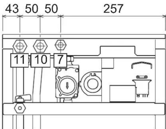
Ma1.13-BoDopobiDiHi wTuepn
7Плобеднaya rasy-1'2"
10 Pma nirn (nona-i) CNTBMA onaneHH-3/4
11 3Bopotha nihir cHTeMM onaneHH - 3/4
Cnctema npotn 3aMeP3aHH, aHTnFpN3Hi pIDHn, npcaKni i cnoBilbHOBaic Kopo3ii
B paai Heo6xiohc0i Do3BoneHO Bkivatn aHtnpnn3H pDHH, npncdkn i cnoBInhOBaui Kop0ii, ane nna 3a yMOBA HauHaHraPapAHII 3 60ky I bNPOMHKB HA bDIOBnIHCT ci npOyKJI py d6Be3NHO KOPcHTYBAHN Ta HbCytHb P3NKy uKoKJKeH DnTENNOoBHmHKNA KOTNa a60 hUHX KOMNoHeHtB I/a60 MATEPIANIB KOTNa T aBCBOrO YCTATKYBAHN. 3a6OpohReTcBc BAOKPCNTAHNA AHTNpM3HIN pIDH, npCADCok i cnoBInhOBaui Kop0ii 3araIbHOI, di He npdAthNX DnBkBaHN y TennOBnx CCTEMax Tae CymICHX 3 MATEPiAMn, BKNOPCTAHMM y KOTNI TA YCTATKYBAHN.
XapakTepeNtKn BODn B KOHTpy OaJIeHHA
JKIOO JOKPCTKICb BOIN nepeBnUe 25° Fr (1°F = 10 NaCTHn HA MINIO CaCO₃), TOnI, ⅢO6 3aONi8y NTBOPENHNO HAKNY y KOTNI, Heo6xIDHO BKNOPCtOBYBaTN CNEIaNbHO 0bOpNBEYBOY.
PiD'ehaHHo do 6oJIepey IraI rapeoi caHTexHIOI BOIN
EneKtpoHnHa nnata KOtna npu3haueHa dnyynpaBniHH 30bHIiHIM 6oNepom dnn BInO6HHTBa rapaHO cAHTEXHIO BOIN. BInOHO tIPOTeXHHNI IINKIOeHHN, BiNOIBHO Do CXEMn Man.14 BInOHO eEnKpTHPi NIDcDHAHN, 3rIHDo oEnKTPnuHO cxemn y man.32 Heo6xIDHO BInKOpHCTOByBATn KOMPNEKT KOJ 1KWMA11W.CnCTema KEpyBaHHKOJI, nID cHAc HAcTyHORo 3anycky, po3nl3Hac 3OHd 6oINepy Ta aBtOMaTNU HO BCTAHOBNT npaAMETPN, yBIMKHyBNI DnCnNeT a BiNObHDI KOMaHDn FyHKUII FBN

man.14-Cxema nid'edhaHH30BHIuHbOro 6oJnepa
8 Buxidrapyoi BOIDCNCTEMI TBN
9 Bxid BOycnCTEmr FBn
10 Ppma nHia (noaui) B KOHTyp onaneHHA
11 3BopOTha nIHr KOHTpy onaneHH
95 BiDbiHn Knaan
3.4Пдкнчeyнraу
I Iepn Hix 3diHCHTN nikJIOHcHHe, nepeKoHaTeCra 0 KOte MoKe npauObaTn 3 HAABHM TINOM PAHBA.
PiknouHra3y Mae 3iHCHOBATNc4o BIDNOBIDHO 8TuCyep (DVB. Man. 13) 3 DOTPMAHHM BMOR YHHORO 3aKOHODABCTBA, METAEBOIO KOPCtKO Tpy6KOHO aBO rHYUKM UANHORM i3 cyUJIbHO CTIHKOO 3 HelpkAbioY O tani, BCTAOHBIOHIO ra30Bn BYHTINb MIX KOHTypOM Ta KOTnM. PepeKohTeCe y NlhoCTr Ra30Bn IqEcdHaB.
3.5 EneKtpnHi niknIOeHHa
Arperat Maic nideHyBaTncb do eefkTBHoi CNTeMn 3a3eMneHHBIOHO 3doTPMaHaHm npabnn 6e3neK EefkTBHICTb Ta BiNobiDHCt CNTeMn 3a3eMNEHH Ma nepeBipTaNCn Nnue paxibuMM, Bnpo6HKn BiXnNHe 6yIbKy BiNobiDaIbHCTb 3a MoKNBni 3bNkn BhacniDok BiCyTHOcTI CNTeMn 3a3eMNEHH
IINI INKIOENH ONEKTPUHOI MEPEXIKOTEN OCHAUEHN KABENEM TINY "Y" 6e3 WtncenE IINKIOENHNOPEXIKOBNHMI MAti KCOBAHE 3EDHAH Ta DBOONIOHCHN PEPIMAKH 3BIDCTAHNI KOKTAKTMIO UOHAMEH3 MM, PO3aTOBOHYOHN 3AN06IKHKNHa HA 3A MIX KOTNOM Ta NIIIEO PPINI INKIOENHDOI NIIHII ENEKTPVHORO XMBNEHH BAKNIBO DOTPMYBAITCM NOJNHOCTI (JIHI: KOPNHEBNIPOBID/HEITPAPJBcHNI pOBID/3EMNJKOOBT-3ENEHN pOBID).
B KOMnTeHJIO KOpNCTyBaHa He BxOaINb 3aMHa Ka6eIO XKIBeHHa Y paai yuKoJodKeHHa Ka6eIO BmKHTb Aperat, NOIT 3EBEPHTCBNO DOnOMONy DO kJIaJIpKOBAHO OaJIbIXI B paII 3aMIHN BOKOPCtOByBaTH NIKIHO NPOBID "HAR H05 VV-F" 3x0,75 MM2 3 MaKcIMANbHM 3OBHIUHdiamETPOM 8 MM.
KimHathHm TePMoCTat (onui)
YBAFA: KOHTAKTI KIMHATHOTO TEPMOCTATY MAOTb EYTN 3AHHI. INPI NIODAHI 230 HA KJIEMI KIMHATHO TO TEPMOCTATY ENEKTPOHHA IINATA BSE3NOBOPOTHO YUKOJXVETCbSRI.
Pnpi nkiKIOeHHxPOHOCTaIB a6o TaImePIB He 6epiTB KINBNEHNN 3 iHX03MKNOuXH KOHTAIB. IX XIKNIEHNN MAE BIKHOYBAITNCJ WNIAXOM 6e3NOcepeHbDO NIKIOeHHN DO MEPEKl A60 3a DOnOMTOO 6atape, 3anexho BI TnA pncTPO.
DocyndoeneKtpnHoi KneMHO naheni
PnIcH3HITTNepehBoHa naHeni ( ) on page 90 () DOCTy DN KEMHOI KOpok6n ENEKTPMHN3cHDAHHMn (Ma1. 5, P03aTuBaHr KIM dI pIHxN iINKIOHHe HabeDHO TAKOX HA eNkTPMHN cXemY mAN. 32

man.15 -DocTyn do KIeMHOi naHeni
3.6 HMOBI Tpy6oPBOOAn
3ayBaXeHHa
JaHn arperat Hanekhtb do "TnHy C", To6To do KOtNIB 3aKpHTO KAMepoIO AropHHI INPmmycoBOIO TAOIO NobITPO3abip I BHXID NIMOBIX RAIB pneDHyKOTCBi DINOHO DO CHCTEM acnpaiit Ta NMOBDAeHNHI, Rk NOBNNH3aDOBONBJHn HabeBDHM HNOHE BMORAM. Nepu HIX npCtynAT Do MONTAKy, YBXAKHO 03HaHMeTCB 3 BIDINOBHMM PnINNCAMM i 3a6eNEte IX cyBOpE DOTPMHAR. KPM TORO, Heo6XIO HOdPTmMyBaNTCA npBNi, Rk CTOCYKBC PoTSAUBAHOr OOrONKBIA H CTHI TA/ABO CTeni, IMIHImaJIbHOI BiCTAHI Bd BIKOH, CTIH, BEHTNRIJHINX OTBOPB, TOTO.
Mokmbi KOnfiprypaui Dmoxoipj imoTahkhi pO3mpn HabeDHeo B Ta6nua 7 iTa6nua 8.
Piiknouenra 3a donomoroIO cnbicnix (koakciaIbHnx) Tpy6
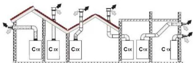
MAN.16-PnKnaI nIKNIOeHH 3a DonOMoHO cnBicHnx (KoakciabHnx) Tpy6 ()=PiobitrpA/BiDnpauBoBahi ra3n
Ta6nua.2-Tunonior
| Ttm | Ömec |
| C1X | 3abip nobiterp i Bmnyck dnmib ropnizhtaln npncnttHn |
| C3X | 3abip nobiterp i Bmnyck dnmib beptnkailn daxobv |
IINr cnBicHOrO npEduHHB BCTAHOBiB HA KOJI IN 3 TAKNX NOATKOBHX ENEMeHTIB. IINr 3AnOoBirAHMOKNIHBOMY 3BOPOTHOMY CTIKAHHO KOHDeHCaTy HAOBHITa KpANAHH NEOxHIO, IO6 MOKNBI ROPNCHTaNbHI YACTNH IN tyPbONpOBID INBdBeDEHH BIDnpaBOBAHN rAIB BCTAHOBINOBAMC 3I NkHM HAXINOM B 6ikKOTNA.
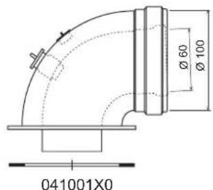
MAN.17-NoaTKoBI eNEMENTn KOaKcianbHx Tpy60npoBqDIB
Ta6nua.3-MakcmaJIbHa DoBxHnA cnibichnx (KoakciabnHx) Tpy6onpoBodIB
| CnibicnH 60/100 | CnibicnH 80/125 | |
| MakcHmAbHNo Do3BolHe Na DobKHe Na (roPn3OHTaIbHa) | 7 M | 28 M |
| MakcHmAbH No Do3BolHe Na DobKHe (BeptnKaIbHa) | 8 M | |
| BeiNCHNa 3MeHueHHa Na KOxHe KOIIHO 90° | 1 M | 0.5 M |
| BeiNCHNa 3MeHueHHa Na KOxHe KOIIHO 45° | 0.5 M | 0.25 M |
IiiknueHHa donomoroB iokpmenxtpy6
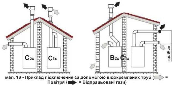
Ta6nua.4-Tunonorria
| Tin Onnc | |
| C1X | Туьбовindяларopy nobirpr i bIDeDhenHbIdipaBbOaHnx ra3iB ropKoHTaNHN nprictHNN. |
| Термдами на bXdoIbIXdoI Maobt 6bYn abo 50кончeTpHmHIMа BO TaKIMN, lob HbIckyotSbdo | |
| Влиму схднixу mob 武у (He bIbSe 50 cm) | |
| C3X | Туьбовindяларopy nobirpr i nobIDeDhenHbIdipaBbOaHnx ra3iB ceptMakHNN daXOBH. |
| Термдами на bXdoIbIXdoIЯ ду C12 | |
| C5X | Забор nobirpr i bIDoxPemHenni bID i dIDeDhenHbIdipaBbOaHnx ra3i nprictHNOBO daXobORO TmY I, y b6du-ЯКOMY pR3i, b 3OZHX a 3PIMHIMa 3NaHcHWMn TnCKy. Trуьбовindяпду bIDeDhenHа bIDpaBbOaHnx ra3i i 3abocpy nobirpr He noBmHIpo3TaOsbOeBAtMCn Ha npOttneHNN crHkax |
| C6X | Забор nobirpr i bIDeDhenHbIdipaBbOaHnx ra3i bonomorOу tv6, ceptHpikObaHnx okpemo (EN 1856/1) |
| B2X | Забор nobirpr 3 npriMiiEHHN 3 yctaHOBeHIM arperatom i bIDaeHnnbIbipaBbOaHnx ra3i npochTHHOBO AO bdo XabORO TMY A BAXIIINO - Y IPMIUIEHHI MAC 3A5E3NEPYBATNCRA HALEXHE BEHTNIIOBAHNR |
IinieiEHaHnB BIOKpemEnHX Tpy6onpoBoID BcTaHOBt Ha arperati TaKni eneMeHT (NobITra = -Dm =)
Bxid nobiterp = /Bxid mMy =
041065X0
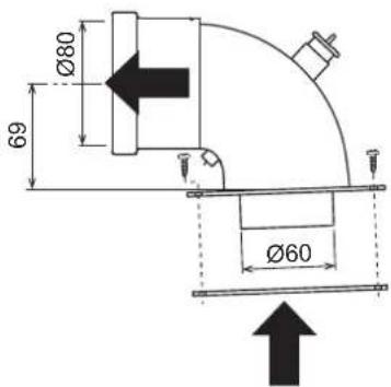

MaI.19NoaTkoBn eEnemET IaBIOkpeMneHx Tpy6OpOBoDIB
Ipeed yctahOBkoIO nepeBipTe, 06 He nepeBmUyBaIacra MaKcIMMaIbHO Do3BOeHa DOBXHnA;3pOBITe 3a DonOMorIO npocTOro po3paxHyK:
- NobHicTIO Bu3HaTe CXemy CnCTeMn PO3DBoEHX DmOxOiB, BkIouaOHNoatKoBI eIemEnI orOIIBK HA BuXOjI.
- 3epehTbcra do Ta6nue 6 i Bn3Haute nKoHpeTHoro BnAky BtpaB N E (ekBiaeneTHnx Metpax) KOxHoro KOMNoEHTy, 3aneKHO BiN NOXKeHHa MOHTaKy.
- Ipepeipte, 06 NOBc yma Bp a 6yna Hxkyo 3a MaKcMaIbHy DoBxHy a60 pibHOIO II,do3BOJeH B Ta6nue 5.
Ta6nua.5-MakmambHa DOBXHb BIDOKpeMneHx Tpy6
IpebeDeHHHa iHnra3XNBHeHH
Koten moke npauoBAtn Ha metaH abo HafTObOMy 3piXeHOMy razi (G.P.L.), i horo Byno hanafojKeHO HA 3abOdi HA BkOPNCtAHN OJHOrO 3 uXx DBOx ra3iB, Ha 10 RCHO Bka3AHO h YA naKOBU Ta HA Ta5hUNu 3 OCHOBHM NEXHHMM DAHMM HA CAMOMY KOTNI Pnp BNHNKHeHHI Heo6DIOCTBI B NKOPNCtAHN r3ay, knn Biip3HReTcB iD nonepeHbO nepe6aHeHORo, Heo6XIOH pMIDatn BiNDOBHIN KOMPNEKT dIra nepeo6NaHaHn I daTn, kR Bka3aHO HIXKHe.
- BmKHTb eJektpnue XNBHeHHB iD KOtNa i 3akpnte ra3OBn BEHTnlb
- 3nTnepeDIO naHEnb i naHEnb repMeTNUHOI kAmePn (nB, Man. 22).
- BiDnyctiB rBnHT i 06epHITb naHeJb 3 KOMaHdAmn (INB.Man.22).
- Po3KpyTITb KOniuaTko C i E i3HimItb ra3OBn knanan (INB, Man. 23).
5.3amhi Tb fOpcyHKy B, BCTaBnEny B rA3OBy Tpy6y, Ha HOby 3 KOMnneKty nepeo6nadHaHH, BCTaBnHouN pOKnAdky D (JIM.B.Man.23). - BctahOBiBt klanah Ha Micce i nepebipte repMeTuHicThb 3eHaHHA.
- 3aipckyTe Ta6nHy KcOMNkTky nepehanarOdkhenH npuy 3a 3abODcbKO T6bnKIO 3 texHHMMDAHHM
- BcTaHOBItb Ha MicCe nepeHIO naHeJIb
- IoanTe XnBneHH HaKOTen i BiIDkpNte ra3OBn BEHTnIb.
- 3mHb napamETp, BiIOBIDHH TNY ra3y:
nepeBeiB kOTen y pexm OykyBaHHa
HATNCHTB HKAHNKCI CNTEMTN BPT (no3.1i2-Man.1Ha 10cekyH:Ha DCNNEI 3'ABNTBC BNIMANBHH HANHC "b01".
HATNCHTb Ha KHONK CNTEMn FBn no3.1 a6o 2 - Man.1, uo6 3aBdatn napametp 00 (dna po60tn Ha metahi) abo 01 (dnpa o60tn Ha ckpanneHomy Hapobomy rasi GPL).
HaTmckaIte Ha KOnky onaeneHH + (no3.4 - Man.1)do noaBn Ha dncnnei 6JIMaIbHorO HanCy "b06".
HANTCHITb H KOHNIO IIN (no3. 1 a62 o - Man. 1), 106 3aBdatni panaMeTp 55 (nraPo60tHa MTaH) a60 70 (nraPo60tHa Na cpkanneneHOMaHafobOmy rasi GPL).
HaHNTCHITb HA KHONK CnCTEmrΓBn (no3.1i2-Ma1.1) BnpoDobx 10 ckyHd
KOTEN NOBEPHeTbCypeKIM OiyKaHHA
- 3a donomorokohahaniatopy 3ropnHH, nIeHaHORo Do BHXOy DmOBnx razB 3 KOthna, nepebiTe BMICT CO_2 y dmOBnx rax3ax, BMKAIOUH KOten HA MaKcMAmbHy H a MIImaBHy NOyHKHCTy, NHO 3haeHHN MaHOt BIDNOBiaTH HabeDeHM y TabNIu3 TexHINMM DaHHM dnniBOIBHO TnHy ra3y.
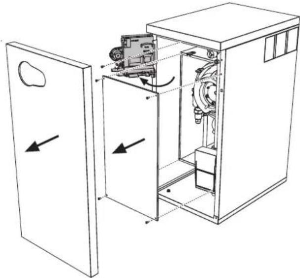
man.22
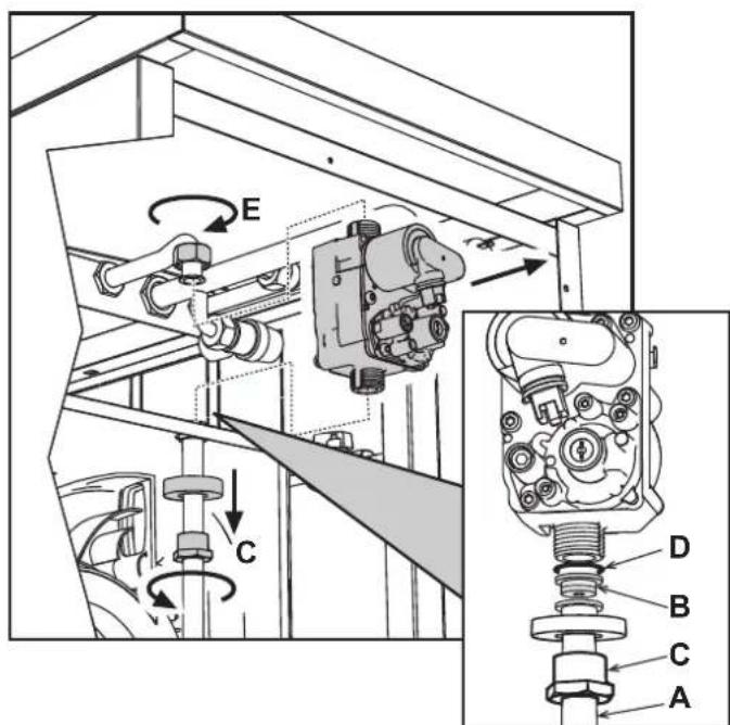
man.23
HaTHCHtB KHONKY CNTEMTN BIN “ (no3.1 - Man. 1) noTkyHCTb KOTnBA DIPa3y X BCTAHOBHOTBCBa HMIIMY (0%) HaTHCHtB KHONKY CNTEMTN BIN “+” (no3.2 - Man. 1) NO TYKHICTb KOTNA BIDp3y X BCTAHOBHOTBCBa HAKCIMYM (100%).
Y pasi akthbaaii pekmy TEST i 3abopy Bdoi fBn, doctaTHbO rnaiktbaui pekmyfBn, koter 3anuactbc B pekmi TEST, ane 3-xoobnn knanan nepmkaetcbc BpekmfBn.
IooB BMKHyTN TECTOBm peXMM TEST, HATNCHTb OHOaCHO Ha KHONKn OAneHnna (no3. 3 Ta 4 - Man. 1) Ha 5 cekyHd.
Pekm TEST B 6by-akomy Binaikky AbotomatnHIO BiDknHHTbCrype3 15 xBnHH a60 no 3abepeuHHi 3abOpy BOi nFBI (y pasi kuo BenuHnHa 3abOpy doCTaTHdAn AKtnBaui jpeKmy FBN).
PerynboHH noTyXHocti onaJIeHH
Дпя permynobHHNotyKHOCTOn aneHnB BCTaHOBt b KOTEN B TECTOBn peKIM TEST (ДИВ. SEZ. 4.1). HatNCHITb ODHoHACHO KHONK OnanIOBAHHa (no3. 3 Ta 4 - Man. 1), ΜO6 36IbWHTn a60 3MeHUnTn NotyKHCtB (MImAmhBa=00, MAKCMaNbHa=100). JAKUO HATNCHYTN KHNKY RESET TA npntpimatn II BnpodOBx 5 cekHy, B JAKOCI MAXcIMaNbHOI NotyKHOCTI ZaHmNTbCra TINbKn Iue BCTAHOBNeHa. BnDITb 3 peKIMMY TectyaBHNAH TEST (ДИВ. SEZ. 4.1)
4.2 Nyck B ekcnnyatauio
Nepu Hix yBIMKHyTN KOTen
- YneBHTbcy y ⅢInbHocTi ra3OBOro KOHtPy.
- Nepebipte niznip y po3wnipOBAhOMy 6aky.
3aONBHITbipabNHHKOHTyp,3abe3neuMbHnOBHN Bnynck nobitpr 3 KOtna Ta 3 KOHTpy.
IpeepieTe,io6 He 6yno BtOKiB BoDN B KOHTpyi OanaHnH, y KOHTypax FBn,Ha 3cndnaHHx a60 y kOtni. - Penebi pte npabnHcIb niknoeHH eJeKtpOyctaKyBaHHa Ta po6Oy CHCTEM 33aMmEHnE
- NpeBipE, 06 3aHcHnTHCKy r3y dIra CNTeMn OanaeHHa 6yNo TAKIM, K0 notpiBHe.
IpeBipte, 606 y 6e3nocepHn 6n3bKocti Bid KOTna He 6yNo JERKOaMMCTNX pinn a60 MaTepiinB
Ipebeipkn niac po6oTn
- yBimKHTb arperat.
- YneBHItbcy y uinbHocti KOHTpy roPiHH i BOaHNxCCTEM.
PepebipnEepeKTHBHCbIMMOxOy i nobitpHNO-IMMOBx Tpy6oPBOBID nIac po60tn KOTna.
YneBHITcB y uinbHocTi ta y cnpabHni po6oTi cnfoHy ta cnCTemn nepep6kn KOHDcHcy. - PpokOHtponHte npabunbHicThc npkpYnlaB BoND MIX KOTNOM i CNTeMaMn.
YneBHITbCByTOMy,IOra3OBnKlanAH npabInbHO npaHoe k y pa3i onaneHH, Taki y pa3i npiroTyBaHHraepoI cantExHIO BOD. - Pēnebipte, qù doβpe Kōtēn pō3naɪnoCTbC, BIVKOBaBni DeKβIbKa npOβhIX pô3nAIIIOBAH i BIMNKaHb 3a dONOMORO kIMHaTHOrO TepMOCTaT a 60 dMCTAHüHOrO KePbAHH.
- Nepebipte BNTPATN JAIINBA 3aJIHNIHbHKOM Ta NOpIbHnIe IX Is 3HAeHHMn y Tabniq TeXHHNDAHN Cap.5.
- PepeKoHaTecs, 0063 3aHHTy Ha onaIeHHa nIbHKn KopeKTHo pO3nAIOCTcB npn BIDkPTTI KpAHy 3 rapAHO BOIOIO. PepeKoHaTecs, 00 nd vac poBOTn Ha onaHHe, npn BIDkPTTI KpAHy 3 rapAHO BOIOO, 3ynHtCbLpKpyLmHn HACOC ONaHHe TBAKOHcyb npriOTyBaHHa CAtEXHHO BoN.
- Pηeβεπe npανβhHcIb npρaPMyBaHHnnapaMeTpiB i BnKoHaTe moKnBe notpiδHe hanaTyBaHH (KOMneHcauiHoI KpNbO,notyKHOCT,tempeaTyPi, too).
4.3 Texhihe o6cnyoByBaHHa
BikpnTnpeepHbOi naHeni
Uo6 Biikpnu 06nBky KOTna, NotrHITb Ha cebe naHenb i Bi'edHaite II (INB. Man.25).
Iepw HIX BHKOHyBaTH 6ydb-aki DII BCEPeHHI KOtna, BiD'cHnTe IHO BiD MepeXi eneKTPuHOro XINBHeHHN n nepeKpTuTe raOBN BeHTnB.
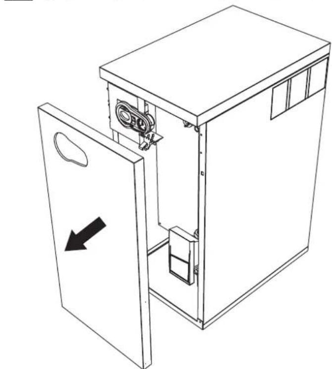
man.25-BiKpTTnpeHboi naHeni
PepiodnHn KOHTpOb
Uo63a6e3neuHn HaneKHy n DOBTOPNBany PO6Oy KOtna, pa3 Ha pik faxiBJI MaOTb BIKHOYBAH Taki nepeBipKn.
Ipnctpoi KepyBaHH I 6e3neKn (ra3OBn KnanaH, Bntpatomip, TepmoCTaTn, Too) NOBHHH cyHKIOHyBatn npabNbHO
KoHTyp BnBeDEHnB BiDnpaBObAHnx r3iB NOBHeH Matn 6e3DoraHy eefekTBHbCTb.
- FepMeTnHaa Kamepa Mae 6yTN uINbHOIO
Poiipno-dmObi trpybopobOdi kHueBi npictpo (o6mexybai) He noHHI Matn nepekoD i BtOKiB
PbIbHNI KTeTNOOIMHHNMIaIOB 6bTuNCTHMn16e3 HauNpy, Jn4 OuMHENHa y p3i0 HeoXidiOCTHe BIKOPICOTyBE XIMAKIN a60 caneBIuNTK.
- EneKtpoMac 6yTu 6e3 HAKINy i npaBnJbHO BCTaHOBNEHM
- Ra3OBI i BO4aHI CnCTeMn MaOTb 6yTu 9iJIbHIMN.
TCK BOy y xOIOHm CNTeMI Mae CTaHOBHTn npu6n3Ho 1bap; kUo Ue He TaK, NOBepHItb Horo Do cboRo 3HaueHH.
LupkyraHnHaoc He noBHe 6yTu 3a5nOKoBaHm.
Po3wnpkoBaNbHn6akMa66yTn3anpaBneHM
Bntpatn Tnck ra3y nobHHI BiDnOBiDaTn Bka3aHmY BiDnOBiHnx Ta6nuaX
CnCTema 3NBy KOHdeHCaty Mac efeKTHBHO npaIOBAtn,6e3 BntOKIB a60 3acMueHb
CnfoHmac6ytn3aONBHeHHBOdoIO
4.4 BpiueHn npo6neM
DiarHocHTka
YpazHnONApOa6o np6bem 3po6TOO dncnnne 6NIMMaTMe Ta Ha HbOMy 3'ABITbcKoD HnONApKn.
DeiHHeNoIaKn CnpuHnHToB NoCTIe 5NOkyBaHH KOTNa (BOH NO3HaauoTbCnitePOIOA).DnI BIDHOBNEHn PO6TOH DCtAHTBO HATNCHNYI KHONKY reset (MHB. 6- Man.1) Ha 1 cekHynd a60 kONKy RESET dNCTaHNIHorO xpoHOCTaTy (NOCTaueTbCn OKPem) B p3AI BHKOPcTAAH N OCTAHbIoro; RkUO KOten He PO3NOHnAE PO6Oy, Tpe6a I cyHytn uH eNoHaKy.
Hui Henoan CnpunnnohTo TMnCuOBe NkOyBaHHa KOTNa BOHN O3HaAHToBcnaItepooF"); NOpeHHnHO pOboTn BID6yBaetcB aBip3ay X nCnN NOpeHHnHAeHHy mEkoPbOOn npapMeTPIKOTNA.
Tabnue HenoJaoK
Tabnua.10-Pepenik Henonapok
| Koia henonadii | Helenonadka | Mochikawa npuichina | Pichiinna |
| A01 | Палынк He poanaioctbca | Biccytncb rasy | Ipepeipre. 4u piianomipn noit kay do kotra I n H bldanene no8tpr 3 tyb6pnoobdoe |
| IopuyenHn y poboti enaktpoda poanaiobanha/ctocpekhena 3a noynm' | Ipepeipre piianomiehne enektpodny ta Iyo no ppaamnue poataauyha, a taox bdychhtb hary | ||
| HecpnaHn raosbni knanah | Ipepeipre I amHn baaoun knanah | ||
| HedcTatHn Tck B mepoxi | Ipepeipre Tck rasy B mepexi | ||
| Cxfonr zacmehn | Ipepeipre Ta a paa Hebcxndocnti omcttb cxfon | ||
| A02 | СинанНаьностсплур'm pri bmmchenomy NaIbHK | IopuyenHn y po6oI enektpoda | Ipepeipre enektporpoedky moHcybantnoHre enektpoda |
| Hcnonadka Pnatt | Ipepeipre Pnatt | ||
| A03 | Сларовуе zaxhiHnmpctpr protni neperpieb | UlyukdoyenHd datnHk Temapetatpyr boDn B otanlOanbHMy KOhyr | Ipepeipre npaHne poostauybaHn i fHykuOyHbANH datnHa Temapetatpyr boDn otanlOanbHoi Cxctem |
| Hnmea ukrpynHn boDn B KOhyr | Ipepeipre ukrpynHnny NompY | ||
| PmocytHc nobTpB KKTypi | Bmycrttb noptpr 3 Kxtyp | ||
| A04 | Сларовуе zaxiHCT trpybONPOBvOy BmIEDEHNH bIdpaabOBAHIX Raiz | Helenonka FUT 3tehepoBaHn trpv 3a octanHn 24rodHn | ДИн.нeноруF OY |
| A05 | Сларовуе zaxiHCT beHnlnatopa | Helenonka F15 noctInho TepepyeBcHn ha protarai 6ke 1 radyn | ДИн.нeноруF15 |
| A06 | Bicytncb polynn'nicr erany poanaianHHN (6 pais 3a 4 XaVnHn) | Helenonka KChLByaBnHO enektpody | Ipepeipre noonokhenny lozHyBaBnHO enektpody Ta b pazl Hebcxldocnti ZamHn. Iyo |
| Hecreabine NpOyMa | Ipepeipre naHnK | ||
| Helenonka Offset (3oyE) raOBoBO knanany | Ipepeipre kanibpyaHn Offset (3oyE) npri minmaHn naTocKocct | ||
| NoBtprHNO-dmOeI trpybONPoBDO zacmehn | BvdaniHs zacmehn 3 dmOaBO Kanaly, tryb6pnoBdoB dln aIpaRpaobanHX rasi Ta noDnHn noBtpr, a TAKOX 3 tyb6Hx orOanAO | ||
| Cxfon Hzacmehn | Ipepeipre Ta paa Hebcxndocnti OMcrttb cxfon | ||
| F07 | ПдankSHAtemepatpya bIdpaabOBAHIX Raiz | DartnK DmH BMHNACnpaHnO Tempepatpy | Ipepeipre Teppoo6mHnK |
| F10 | IopuyenHn y po6oTI daTnHn temepatpyr boDn I b pRnMoH koHpyr (noDnH) oanlOanbHoi CCTEMH | UlyukdoyenHd datnHk | Ipepeipre enektporpoBdoK afo ZamHn dtatHnk |
| 3SMMKHN B e ENEKTPoBPOBdoJ | |||
| PoxpiB eNEKTPoBPOBdoJ | |||
| F11 | IopuyenHn y po6oTI daTnHn ZbOPOTHoi NiH | UlyukdoyenHd datnHk | Ipepeipre enektporpoBdoK afo ZamHn dtatHnk |
| 3SMMKHN B e ENEKTPoBPOBdoJ | |||
| PoxpiB eNEKTPoBPOBdoJ | |||
| F12 | Helenonda DaTnHn temepatpyr boDn B KOhyrГT | UlyukdoyenHd datnHk | Ipepeipre enektporpoBdoK afo ZamHn dtatHnk |
| 3SMMKHN B e ENEKTPoBPOBdoJ | |||
| PoxpiB eNEKTPoBPOBdoJ | |||
| F13 | Helenonda DaTnHn daTnHn Raiz | UlyukdoyenHd datnHk | Ipepeipre enektporpoBdoK afo ZamHn dtatHnk |
| 3SMMKHN B e ENEKTPoBPOBdoJ | |||
| PoxpiB eNEKTPoBPOBdoJ | |||
| F14 | IopuyenHn y po6oTI daTnHn temepatpyr boDn I b pRnMoH koHpyr (noDnH) oanlOanbHoi CCTEMH | UlyukdoyenHd datnHk | Ipepeipre enektporpoBdoK afo ZamHn dtatHnk |
| PoxpiB eNEKTPoBPOBdoJ | |||
| F15 | Helenonda Y beHnHnTpor | HedcStaTH MTK XmHnEHNH (RIM Mae ouadatm Z30B) | Ipepeipre enektporpoBdoK 8- nomoCHOro pOaEma |
| He naHxOuHb CnHn Bid liHnMbHnO bOeptna | Ipepeipre enektporpoBdoK 8- nomoCHOro pOaEma | ||
| HectpAan BENTHnTpor | Ipepeipre bentHnTpor | ||
| F34 | Hampyrta XmHnEHNH E noHnKO 3a 170B | Ipo6bEmn B e ENKTPuHn MepeK | Ipepeipre enektpoyctatKyaBaHn |
| F35 | HelenonmaHb Nactota StpyM B eNEKTPaHn MepeK | Ipo6bEmn B e ENKTPuHn MepeK | Ipepeipre enektpoyctatKyaBaHn |
| F37 | HelenaunHn Tck BoDn koHpyr OlanenHn | Tuck ZaHAnTO HcHbOn | ZaHnHtcb ChcTeMу AOdo |
| Pete Tcky BoDn He ndeHne abo yukOuOdunne | Ipepeipre datHnk | ||
| F39 | Helenonda ZoeHnHbTo 3OOna | UlyukdoyenHd 3OOn ABO KoptK ZAMKHN Hb ENEKTPoBPOBdoJ | Ipepeipre enektporpoBdoK afo ZamHn dtatHnk |
| 3OOna BicdEaDaBcN CiTae aMnBuBAAHn RApMly 3a notoHnHO temepatpyro | 3OOny NcIcDaaite ToBAtuHn 3OOnd Abo aMmHn BpKMM noToCnHO ttemepatpyr | ||
| A41 A44 | PoztauYBaHn DaTnHn | DatnvK Tempepatryn OanlOanbTuHc StcTEm Bic'dcuaBcBid Tpyb | Ipepeipre enektporpoBdoK afo fHyuOuHyBaHn DaTnHn Tempepatryn BoDn OanlOanbTuHn CCTEM |
| A42 | Helenonda DaTnHn temepatpyr BoDn B oanlOanbHn Cxctem | UlyukdoyenHd datnHk | ZamHtcb dtatHnk |
Y npabii KOONHnI NOKa3aHI CKOpOeHHRA, BIKOPNCTOByBaHI Na TabnHcI 3 TeHXHIM DaHMM.
THE DECLARATION OF CONFORMITY MAY BE REQUESTED FROM THE MANUFACTURER.
FR LE MARQUAGE CATTESTE QUE LES PRODUITS SONT CONFORMES AUX EXIGENCES ESSENTIELLES DE L'ENSEMBLE DES DIRECTIVES QUI LEURS ARENT APPLICABLES.
LA DÉCLARATION CE DE CONFORMITE PEUT ÉTRE DEMANDÉE AU FABRICANT.
RU MAPKINPOBKA CENoTBEPJAET,HTO PNOyKUNA COOTBETCTBYET OCHOBHbIM TPE6OBAHnAM COOTBETCTBYUOUX DEICTBYUOUX INPEKTNB.
DEKJIAPAUZIO COOTBETCTBUN MOKET BbITb 3ATPE6OBAHA Y IPOU3BOIDTEJIA.
UK MAPKYBAHHA C 3ACBIIDYE BIDIOBIDHICTb BNPOIB OCHOBHIM BNMOTAM INPEKTNB,IIIOUHX Y FAJY3I.
DEKJIAPAciIO IPO BIIDIOBIDHCTb MOXHA 3AINTATN Y BNIPOBnKA.
The unit and its accessories must be appropriately disposed of in compliance with current regulations.

- C E
- IT
- 1.AVVERTENZE GENERALI
- OPERATING INSTRUCTIONS
- Introduction
- Panel - legend fig. 1
- Indication during operation
- Heating
- Domestic hot water (DHW)
- Fault
- Connection to the power supply, switching on and off
- Boiler electrically powered
- Switching the boiler off and on
- Adjustments
- Summer/Winter Swithchover
- Heating temperature adjustment
- DHW temperature adjustment
- Room temperature adjustment (with optional room thermostat)
- Room temperature adjustment (with optional remote timer control)
- Hot water tank exclusion (economy)
- Sliding Temperature
- Adjustments from Remote Timer Control
- Plumbing system pressure adjustment
- INSTALLATION
- General Instructions
- Place of installation
- Plumbing connections
- Important
- Antifreeze system, antifreeze fluids, additives and inhibitors
- Water system characteristics
- Connection to a storage tank for domestic hot water production
- Gas connection
- Electrical connections
- Room thermostat (optional)
- Accessing the electrical terminal block
- Fume ducts
- Connection with coaxial pipes
- Condensate drain connection
- SERVICE AND MAINTENANCE
- Adjustments
- Gas conversion
- TEST mode activation
- Heating power adjustment
- Startup
- Before lighting the boiler
- Checks during operation
- Maintenance
- Opening the front panel
- Periodical check
- Troubleshooting
- Diagnostics
- Table of faults
- TECHNICAL DATA AND CHARACTERISTICS
- General view and main components
- Diagrams
- Technical data table
- rprodufohe
- Temperature evolutive
- Raccordement gaz
- YcnoBhble 6o3haeHnHa naHEn ynpaBneHn pnc.1
- HdkauaBOBpeMa pa60tkoTna
- PexMMOTONJIeHn
- Pexn m ropayero BOOCha6xHn
- HemcpabHOCTb
- Koten nodknouehen K cetn 3neKtponntaHna
- BkHoueHn H BbIKHoueHne KOTna
- PerynipOBKn
- IpeeknuehnepekmOB"JTo""3Ma
- PerynpobkA TeMnepaTpybI BOdbICNTeMe OTonneH
- PerynpoBka temnepaTpyb B cnCTme ropayero BOOChaeHHA (TB)
- NckHoueHHe 60nepa (peXHM "3KOHOMnHbI")
- RaObIe coEHHHeHn
- 3neKtpnueckne coeHHeHHa
- Tepmoctat TemnepaotypbI BO3dyxa B nOmeueHIN (onu)
- DocTyK KJIeMMHO KoPobKe
- 3.6ДыбIMOXOДы
- PpeDynpexkdeHn
- PoiocoeHHeHcNOMOuBkoAChnJIbHbIX Tpy6
- 041065X0
- Perynpobka Mouhoctn OTONHeH
- BbO D B 3KcNpyTaumH
- IpeepBknHoueHHemKOTna
- KoHTpoIbHbIe onepaunn BO Bpempa60tbl
- 4.3TexHueeckoe 06cnykmbaHne
- OTkpBtne nepedne naHei
- PepnoDnueckne npOBepkn
- YctpaHHe HncpabHocte
- DnarHOCTNka
- Ta6nua HncnpaBnOtei
- 5.XAPAKTEPNUCTKINTEXHNueCKNE DAHHbIE
- HaKoTeI noaCTbC eJeKtpnHc KnBHeHH
- BmKHeHH ybIMKHeHH KOtna
- PerynobAHn
- IpeemkaHnHa Estate/Inverno (Ito/3ma)
- PerynIOBaHHaTeMnepaTypOnaJIeHHa
- PerynboHHr TemepaTyB CNTeMI B
- BuknoeHHa 3 po6oTu boHnepa (ekOHomUchn peXm economy)
- Notocha temnepaTpa
- PerynoBaHHn DaCTaHuiHoro xpoHOcTaty
- PerynIOBaHHr iipabniHOro Tcky y KOHTpyi onaneHH
- MOHTAX
- 3aralbi noonoxehn
- Mlue dna BCTaHOBnEHn
- 3.3Iipotexhiyhi nkiKnyeHHA
- 3ayBaXeHHH
- Cnctema npotn 3aMeP3aHH, aHTnFpN3Hi pIDHn, npcaKni i cnoBilbHOBaic Kopo3ii
- XapakTepeNtKn BODn B KOHTpy OaJIeHHA
- PiD'ehaHHo do 6oJIepey IraI rapeoi caHTexHIOI BOIN
- 3.4Пдкнчeyнraу
- EneKtpnHi niknIOeHHa
- KimHathHm TePMoCTat (onui)
- DocyndoeneKtpnHoi KneMHO naheni
- HMOBI Tpy6oPBOOAn
- 3ayBaXeHHa
- MaI.19NoaTkoBn eEnemET IaBIOkpeMneHx Tpy6OpOBoDIB
- IpebeDeHHHa iHnra3XNBHeHH
- PerynboHH noTyXHocti onaJIeHH
- Nyck B ekcnnyatauio
- Nepu Hix yBIMKHyTN KOTen
- Ipebeipkn niac po6oTn
- Texhihe o6cnyoByBaHHa
- BikpnTnpeepHbOi naHeni
- PepiodnHn KOHTpOb
- BpiueHn npo6neM
- DiarHocHTka
- Tabnue HenoJaoK
Brand : FERROLI
Model : Bluehelix B 35
Category : Central heating boiler