
Atlas D Eco K Unit - Heat pump FERROLI - Free user manual and instructions
Find the device manual for free Atlas D Eco K Unit FERROLI in PDF.
| Product type | High-efficiency oil boiler with domestic hot water production |
| Brand | Ferroli |
| Model | Atlas D Eco K Unit (variants 30 K 100 UNIT and 42 K 130 UNIT) |
| Dimensions (L x W x H) | Refer to the diagrams in the manual (fig. 43-46) for exact dimensions |
| Empty weight | 225 kg (30 K model) / 265 kg (42 K model) |
| Power supply | 230 V / 50 Hz |
| Rated thermal output | 25 kW (30 K) / 37 kW (42 K) in high temperature operation |
| Full load efficiency | 88.2% (30 K) / 88.3% (42 K) on Hs |
| Fuel | Diesel (oil) |
| Domestic hot water tank capacity | 90 liters (30 K) / 117 liters (42 K) |
| Max heating service pressure | 6 bar |
| Max heating temperature | 110 °C |
| Heating expansion vessel capacity | 10 liters |
| Protection rating | X0D |
| Main functions | Central heating, domestic hot water production, Summer/Winter mode, Eco/Comfort mode, climatic regulation (with optional outdoor sensor) |
| Maintenance and cleaning | Annual maintenance required by a qualified professional. Clean the casing with a soft, damp cloth, without abrasive products. |
| Safety devices | Safety valve, frost protection, safety thermostats, pressure sensor, self-diagnosis with error codes |
| Spare parts and repairability | Use only original spare parts. Magnesium anode, nozzle, electrodes, circulator, etc. require professional intervention. |
| General information | Non-condensing appliance, low temperature type. Energy efficiency class B (heating) and B (DHW). Sound power 62 dB(A). |
Frequently Asked Questions - Atlas D Eco K Unit FERROLI
User questions about Atlas D Eco K Unit FERROLI
0 question about this device. Answer the ones you know or ask your own.
Ask a new question about this device
Download the instructions for your Heat pump in PDF format for free! Find your manual Atlas D Eco K Unit - FERROLI and take your electronic device back in hand. On this page are published all the documents necessary for the use of your device. Atlas D Eco K Unit by FERROLI.
USER MANUAL Atlas D Eco K Unit FERROLI
ATLAS D ECO 30/42 K 100/130 UNIT

natural_image
Exterior view of a silver Ferroli portable appliance (no signage or text beyond brand name)
cod. 3541Q563 - Rev. 00 - 10/2021
CE
IT - ISTRUZIONE PER L'USO L'INSTALLAZIONE E LA MANUTENZIONE
ES - INSTRUCCIONES DE USO, INSTALACIÓN Y MANTENIMIENTO
EN - INSTRUCTIONS FOR USE, INSTALLATION AND MAINTENANCE
FR - INSTRUCTIONS D'UTILISATION, D'INSTALLATION ET D'ENTRETIEN
NL - AANWIJZINGEN VOOR GEBRUIK, INSTALLATIE EN ONDERHOUD
EL- OΔΗΓΙΕΣ ΧΡΗΣΗΣ, ΕΓΚΑΤΑΣΤΑΣΗΣ ΚΑΙ ΣΥΝΤΗΡΗΣΗΣ
IT
1. AVVERTENZE GENERALI
fig. 3
fig. 5 - Accensione caldaia
fig. 8
line
| OFFSET | X | Y | |--------|------|------| | 20 | 20 | 20 | | 20 | -20 | 20 | | 10 | 10 | 85 | | 10 | -10 | 75 | | 9 | 9 | 65 | | 9 | -9 | 55 | | 8 | 8 | 50 | | 8 | -8 | 45 | | 7 | 7 | 40 | | 7 | -7 | 35 | | 6 | 6 | 30 | | 6 | -6 | 25 | | 5 | 5 | 20 | | 5 | -5 | 15 | | 4 | 4 | 10 | | 4 | -4 | 5 | | 3 | 3 | 0 | | 3 | -3 | -5 | | 2 | 2 | -10 | | 2 | -2 | -15 | | 1 | 1 | -20 | | 1 | -1 | -25 | | OFFSET = 40; Y-axis range: -20 to 90; OFFSET = 1 to 10; OFFSET = 2 to 40; OFFSET = 40; OFFSET = 6 to 80; OFFSET = 8 to 100; OFFSET = 100; OFFSET = 120; OFFSET = 140; OFFSET = 160; OFFSET = 180; OFFSET = 200; OFFSET = 220; OFFSET = 240; OFFSET = 260; OFFSET = 280; OFFSET = 300; OFFSET = 320; OFFSET = 340; OFFSET = 360; OFFSET = 380; OFFSET = 400; OFFSET = 420; OFFSET = 440; OFFSET = 460; OFFSET = 480; OFFSET = 500; OFFSET = 520; OFFSET = 540; OFFSET = 560; OFFSET = 580; OFFSET = 600; OFFSET = 620; OFFSET = 640; OFFSET = 660; OFFSET = 680; OFFSET = 700; OFFSET = 720; OFFSET = 740; OFFSET = 760; OFFSET = 780; OFFSET = 800; OFFSET = 820; OFFSET = 840; OFFSET = 860; OFFSET = 880; OFFSET = 900; OFFSET = 920; OFFSET = 940; OFFSET = 960; OFFSET = 980; OFFSET = 1000; OFFSET = 1200; OFFSET = 1400; OFFSET = 1600; OFFSET = 1800; OFFSET = 2000; OFFSET = 2200; OFFSET = 2400; OFFSET = 2600; OFFSET = 2800; OFFSET = 3000; OFFSET = 3200; OFFSET = 3400; OFFSET = 3600; OFFSET = 3800; OFFSET = 4000fig. 19
natural_image
Technical line drawing of a mechanical device with control panel and indicator lights, shown in an inset view (no text or symbols present)fig. 22
natural_image
Technical line drawing of a mechanical assembly with hoses and a housing (no text or symbols)fig. 31 - Pompa ITALPUMP
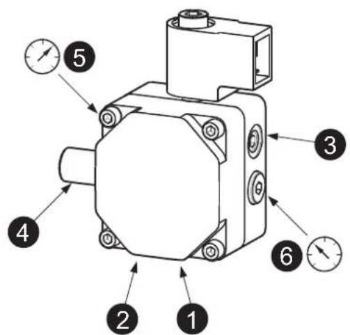
fig. 32 - Pompa DANFOSS
fig. 33
fig. 34
fig. 38
fig. 39
fig. 40
natural_image
Close-up of a Wilo industrial control unit with a red dial and black arrow pointing to it (no readable text or symbols beyond branding)fig. 41
fig. 42
Legenda figure cap. 5
line
| Q [m³/h] | Line 1 | Line 2 | Line 3 | | -------- | ------ | ------ | ------ | | 0 | 2.0 | 4.5 | 7.0 | | 0.5 | 2.0 | 4.5 | 7.5 | | 1.0 | 1.5 | 4.0 | 6.0 | | 1.5 | 1.0 | 3.5 | 4.5 | | 2.0 | 0.5 | 3.0 | 3.0 | | 2.5 | 0.0 | 2.5 | 1.5 | | 3.0 | 0.0 | 2.0 | 1.0 |natural_image
Technical line drawing of a mechanical device with control panel and display screen (no text or symbols)fig. 22
natural_image
Technical line drawing of a mechanical assembly with hoses and a central component (no text or symbols)fig. 30 - Modo TEST
fig. 31- Bomba ITALPUMP
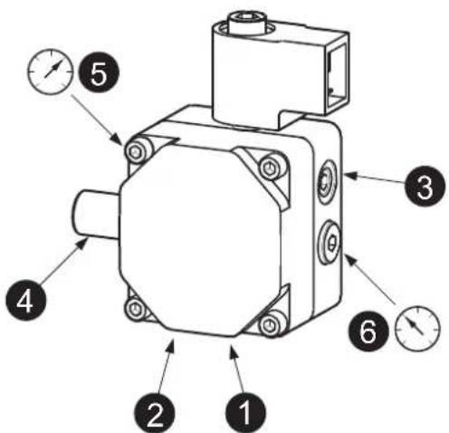
fig. 32- Bomba DANFOSS
fig. 33
fig. 34
fig. 38
fig. 39
fig. 40
fig. 42
line
| Q [m³/h] | Line 1 | Line 2 | Line 3 | | -------- | ------ | ------ | ------ | | 0 | 2.5 | 4.5 | 7.0 | | 0.5 | 2.5 | 4.5 | 7.5 | | 1.0 | 2.0 | 4.0 | 6.0 | | 1.5 | 1.5 | 3.5 | 4.5 | | 2.0 | 1.0 | 3.0 | 3.0 | | 2.5 | 0.5 | 2.5 | 1.5 | | 3.0 | 0.0 | 2.0 | 0.0 |- Read the warnings in this instruction booklet carefully since they provide important information on safe installation, use and maintenance.
- This instruction booklet is an integral and essential part of the product and must be kept with care by the user for future reference.
- If the unit is sold or transferred to another owner or if it is to be moved, always make sure the booklet stays with the boiler so that it can be consulted by the new owner and/or installer.
- Installation and maintenance must be carried out by professionally qualified personnel, according to current regulations and the manufacturer's instructions.
- Incorrect installation or inadequate maintenance can result in damage or injury. The manufacturer declines any liability for damage caused by errors in installation and use or by failure to follow the instructions provided.
- Before carrying out any cleaning or maintenance operation, disconnect the unit from the power supply using the system switch and/or the special cut-off devices.
- In case of a fault and/or poor operation, deactivate the unit and do not try to repair it or directly intervene. Contact professionally qualified personnel. Any repair/replacement of the products must only be carried out by qualified personnel using genuine parts. Failure to comply with the above can compromise the safety of the unit.
- Periodic maintenance performed by qualified personnel is essential in order to ensure proper operation of the unit.
- This unit must only be used for its intended purpose. Any other use is deemed improper and therefore hazardous.
-
After unpacking, check the good condition of the contents. The packing materials are potentially hazardous and must not be left within the reach of children.
-
The unit can be used by children aged at least 8 years and by persons with reduced physical, sensory or mental capabilities, or lacking experience or the necessary knowledge, only if under supervision or they have received instructions on its safe use and the related risks. Children must not play with the unit. Cleaning and maintenance intended to be done by the user can be carried out by children aged at least 8 years only if under supervision.
- In case of doubt, do not use the unit. Contact the supplier.
- The unit and its accessories must be appropriately disposed of in compliance with current regulations.
- The images given in this manual are a simplified representation of the product. In this representation there may be slight and insignificant differences with respect to the product supplied.
THE CE MARKING CERTIFIES THAT THE PRODUCTS MEET THE ESSENTIAL REQUIREMENTS OF

THE RELEVANT DIRECTIVES IN FORCE. THE DECLARATION OF CONFORMITY MAY BE REQUESTED FROM THE MANUFACTURER.
This symbol, which is used on the product, packaging or documents, means that at the end of its useful life, this product must not be collected, recycled or disposed of together with domestic waste.
Improper management of electric or electronic waste can lead to the leakage of hazardous substances contained in the product. For the purpose of preventing damage to health or the environment, users are kindly asked to separate this equipment from other types of waste and to ask for it to be dealt with by the municipal waste service or dealer under the conditions and according to the methods set down in national and international laws transposing the Directive 2012/19/EU.
2. OPERATING INSTRUCTIONS
2.1 Introduction
Dear Customer,
Thank you for choosing a FERROLI boiler featuring advanced design, cutting-edge technology, high reliability and quality construction. Please read this manual carefully since it provides important information on safe installation, use and maintenance.
ATLAS D ECO 30/42 K 100/130 UNIT is a high-efficiency heat generator for domestic hot water production and heating, using an oil burner. The boiler shell consists of cast-iron elements, assembled with double cones and steel stays placed over a DHW quick storage domestic hot water tank, vitrified, and protected against corrosion by a magnesium anode. The control system is with microprocessor and digital interface with advanced temperature control functions.
2.2 Control panel
Panel
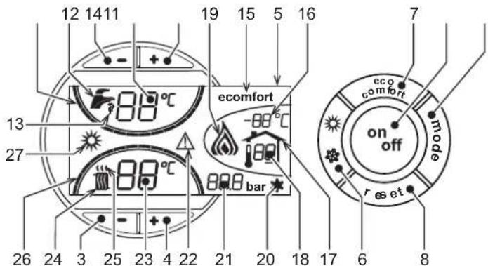
fig. 1 - Control panel
Panel key
1 = DHW temperature setting decrease button
2 = DHW temperature setting increase button
3 = Heating system temperature setting decrease button
4 = Heating system temperature setting increase button
5 = Display
6 = Summer / Winter mode selection button
7 = Economy / Comfort mode selection button
8 = Reset button
9 = Unit On / Off button
10 = "Sliding Temperature" menu button
11 = Set DHW temperature reached
12 = DHW symbol
13 = DHW mode
14 = DHW outlet temperature / setting
15 = Eco (Economy) or Comfort mode
16 = External sensor temperature (with optional external probe)
17 = Appears on connecting the external Probe or the Remote Timer Control (optionals)
18 = Room temperature (with optional Remote Timer Control)
19 = Burner On
20 = Antifreeze operation
21 = Heating system pressure
22 = Fault
23 = Heating delivery temperature/setting
24 = Heating symbol
25 = Heating mode
26 = Set heating delivery temperature reached
27 = Summer mode
Indication during operation
Heating
A heating demand (generated by the Room Thermostat or Remote Timer Control) is indicated by flashing of the hot air above the radiator (details 24 and 25 - fig. 1).
The heating graduation marks (detail 26 - fig. 1) light up as the heating sensor temperature reaches the set value.
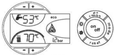
fig. 2
DHW (Comfort)
A DHW demand (generated by drawing domestic hot water) is indicated by flashing of the hot water under the tap (details 12 and 13 - fig. 1). Make sure the Comfort function (detail 15 - fig. 1) is activated
The DHW graduation marks (detail 11 - fig. 1) light up as the DHW sensor temperature reaches the set value.
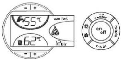
fig. 3
Exclude hot water tank (economy)
Hot water tank temperature maintaining/heating can be excluded by the user. If excluded, domestic hot water will not be delivered.
When hot water tank heating is activated (default setting), the COMFORT symbol (detail 15 - fig. 1) is activated on the display, and when off, the ECO symbol (detail 15 - fig. 1) is activated on the display
The hot water tank can be deactivated by the user (ECO mode) by pressing the eco/comfortfig. 1 button (detail 7 -). To activate the COMFORT mode, press the eco/comfort button (detail 7 -) fig. 1 again.
2.3 Lighting and turning off
Boiler not electrically powered
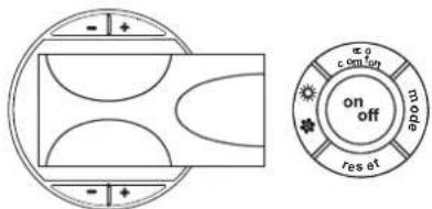
fig. 4 - Boiler not electrically powered
The antifreeze system does not work when the power and/or gas to the unit are turned off. To avoid damage caused by freezing during long idle periods in winter, it is advisable to drain all water from the boiler, DHW circuit and system; or drain just the DHW circuit and add a suitable antifreeze to the heating system, complying with that prescribed in sec. 3.3.
Boiler lighting
- Open the fuel on-off valves.
- Switch on the power to the unit.
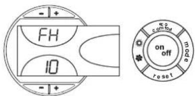
fig. 5 - Boiler lighting
- For the following 120 seconds the display will show FH which identifies the heating system air venting cycle.
- During the first 5 seconds the display will also show the card software version.
- When the message FH disappears, the boiler is ready to operate automatically whenever domestic hot water is drawn or in case of a room thermostat demand.
Turning the boiler off
Press the on/off button (detail 9 - fig. 1) for 1 second.
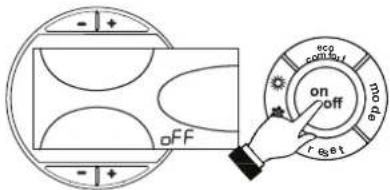
fig. 6 - Turning the boiler off
When the boiler is turned off, the PCB is still powered.
Domestic hot water and heating are disabled. The antifreeze system remains activated.
To relight the boiler, press the on/off button (detail 9 - fig. 1) again for 1 second.
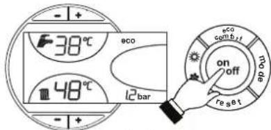
fig. 7
The boiler will be immediately ready to operate whenever domestic hot water is drawn or in case of a room thermostat demand.
2.4 Adjustments
Summer/Winter Switchover
Press the summer/winter button (detail 6 - fig. 1) for 1 second.
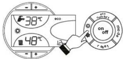
fig. 8
The display activates the Summer symbol (detail 27 - fig. 1): the boiler will only deliver domestic hot water. The antifreeze system remains activated.
To deactivate the Summer mode, press the summer/winter button (part. 6 - fig. 1) again for 1 second.
Heating temperature setting
Use the heating buttons (details 3 and 4 - fig. 1) to adjust the temperature from a min. of 30^ C to a max. of 80^ C.
In any case it is advisable not to operate the boiler below 45°C.
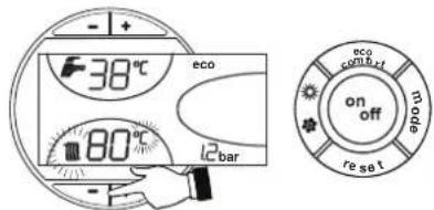
fig. 9
DHW temperature adjustment
Use the DHW buttons -/+ (details 1 and 2 - fig. 1) to adjust the temperature from a min. of 10°C to a max. of 65°C.
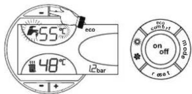
fig. 10
Room temperature adjustment (with optional room thermostat)
Using the room thermostat, set the temperature desired in the rooms. If the room thermostat is not installed the boiler will keep the heating system at its setpoint temperature.
Room temperature adjustment (with optional remote timer control)
Using the remote timer control, set the temperature desired in the rooms. The boiler unit will set the system water according to the required room temperature. For information on the remote timer control, please refer to its user's manual.
Sliding temperature
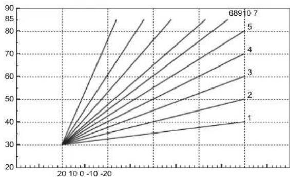
When the optional external probe is installed the control panel display (detail 5 - fig. 1) shows the actual outside temperature read by the probe. The boiler control system operates with "Sliding Temperature". In this mode, the temperature of the heating system is adjusted according the outside weather conditions, in order to ensure high comfort and energy saving throughout the year. In particular, as the outside temperature increases, the system delivery temperature is decreased according to a specific "compensation curve".
With Sliding Temperature adjustment, the temperature set with the heating buttons -/+ (details 3 and 4 - fig. 1) becomes the maximum system delivery temperature. It is advisable to set a maximum value to allow system adjustment throughout its useful operating range.
The boiler must be adjusted at the time of installation by qualified personnel. Possible adjustments can in any case be made by the user to improve comfort.
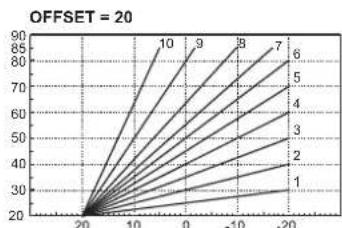
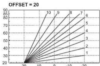
Compensation curve and curve offset
Press the mode button (detail 10 - fig. 1) once to display the actual compensation curve (fig. 11), which can be modified with the DHW buttons (details 1 and 2 - fig. 1).
Adjust the required curve from 1 to 10 according to the characteristic (fig. 13).
By setting the curve to 0, sliding temperature adjustment is disabled.
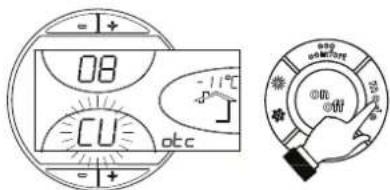
fig. 11 - Compensation curve
Press the heating buttons (details 3 and 4 - fig. 1) to access parallel curve offset (fig. 14), modifiable with the DHW buttons (details 1 and 2 - fig. 1).
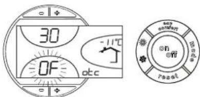
fig. 12 - Curve parallel offset
Press the mode button (detail 10 - fig. 1) again to exit parallel curve adjustment mode. If the room temperature is lower than the required value, it is advisable to set a higher order curve and vice versa. Proceed by increasing or decreasing in steps of one and check the result in the room.
line
| X | Y | |---|---| | 20 | 30 | | 10 | 35 | | -10 | 40 | | -20 | 45 | | 689 | 85 | | 10 | 80 | | 7 | 75 | | 5 | 70 | | 4 | 65 | | 3 | 60 | | 2 | 55 | | 1 | 50 | The chart displays a single data series with values labeled above the lines. The x-axis ranges from -20 to 20, and the y-axis ranges from 20 to 90. There is no additional data series or labels present in the chart.fig. 13 - Compensation curves
line
| x | y | |----|------| | 20 | 20 | | 10 | 30 | | 0 | 40 | | -10| 50 | | -20| 60 |
line
| x | y | |----|------| | 20 | 40 | | 10 | 85 | | 0 | 90 | | -10| 75 | | -20| 60 |fig. 14 - Example of compensation parallel curve offset
Adjustments from Remote Timer Control

If the Remote Timer Control (optional) is connected to the boiler, the above adjustments are managed according to that given in table 1. Also, the control panel display (detail 5 - fig. 1) shows the actual room temperature detected by the Remote Timer Control.
Table. 1
| Heating temperature setting | Adjustment can be made from the Remote Timer Control menu and the boiler control panel. |
| DHW temperature adjustment | Adjustment can be made from the Remote Timer Control menu and the boiler control panel. |
| Summer/Winter Switchover | Summer mode has priority over a possible Remote Timer Control heating demand. |
| Eco/Comfort selection | On disabling DHW from the Remote Timer Control menu, the boiler selects the Economy mode. In this condition, the button 7 -fig. 1 on the boiler panel is disabled. |
| On enabling DHW from the Remote Timer Control menu, the boiler selects the Comfort mode. In this condition it is possible select one of the two modes with the button 7 -fig. 1 on the boiler panel. | |
| Sliding Temperature | Both the Remote Timer Control and the boiler card manage Sliding Temperature adjustment: of the two, the Sliding Temperature of the boiler card has priority. |
System water pressure adjustment
The filling pressure with system cold, read on the display, must be approx. 1.0 bar. If the system pressure falls to values below minimum, the boiler card will activate fault F37 (fig. 15).
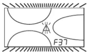
fig. 15 - Low system pressure fault
Optional filling cock and vessel kit
An optional kit comprising a DHW expansion vessel and a filling cock is available on request.
The filling cock must be installed respecting the direction of the arrow.
When installed, operate the filling cock (detail 1 - fig. 16) to bring the system pressure to a value above 1.0 bar.
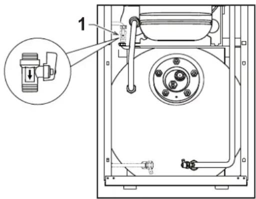
fig. 16- Filling cock (optional)

Once the system pressure is restored, the boiler will activate the 120-second air venting cycle indicated on the display by FH.
3. INSTALLATION
3.1 General Instructions
BOILER INSTALLATION MUST ONLY BE PERFORMED BY QUALIFIED PERSONNEL, IN ACCORDANCE WITH ALL THE INSTRUCTIONS GIVEN IN THIS TECHNICAL MANUAL, THE PROVISIONS OF CURRENT LAW, THE PRESCRIPTIONS OF NATIONAL AND LOCAL STANDARDS AND THE RULES OF PROPER WORKMANSHIP.
3.2 Place of installation
The boiler unit must be installed in a specific room with ventilation openings to the outside as prescribed by current regulations. If there are several burners or suction units that can work together in the same room, the ventilation openings must be sized for simultaneous operation of all the units. The place of installation must be free of flammable materials or objects, corrosive gases, powders or volatile substances that, conveyed by the burner fan, can obstruct the internal lines of the burner or the combustion head. The room must be dry and not exposed to rain, snow or frost.

If the unit is enclosed in a cabinet or mounted alongside, a space must be provided for removing the casing and for normal maintenance operations.
3.3 Plumbing connections
Important
The heating capacity of the unit must be previously established by calculating the building's heat requirement according to the current regulations. The system must be provided with all the components for correct and regular operation. It is advisable to install shutoff valves between the boiler and heating system allowing the boiler to be isolated from the system if necessary.

The safety valve outlet must be connected to a funnel or collection pipe to prevent water spurting onto the floor in case of overpressure in the heating circuit. Otherwise, if the discharge valve cuts in and floods the room, the boiler manufacturer cannot be held liable.
Do not use the water system pipes to earth electrical appliances.
Before installation, flush all the pipes of the system thoroughly to remove any residuals or impurities that could affect proper operation of the unit.
Carry out the relevant connections according to the diagram in cap. 5 and the symbols given on the unit.

Install on the cold water inlet the safety check valve "A" (see fig. 17) supplied with the boiler. Respect the direction of the arrow on the valve.
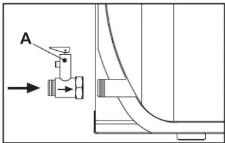
fig. 17 - Safety check valve installation

Install on the system delivery the non-return valve "A" (see fig. 18) supplied with the boiler, interposing the gasket "B". Respect the direction of the arrow on the valve.

fig. 18 - Non-return valve installation
High efficiency hot water tank circulating pump
For proper operation of the boiler ATLAS D ECO 30/42 K 100/130 UNIT, the speed selector (see fig. 19) must be set to position III.
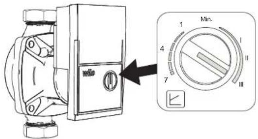
fig. 19
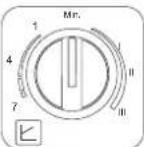
High efficiency heating circulating pump
The factory setting is suitable for all installations; however a different operation strategy can be set, depending on the characteristics of the system.
Setting Dp-v
Proportional head
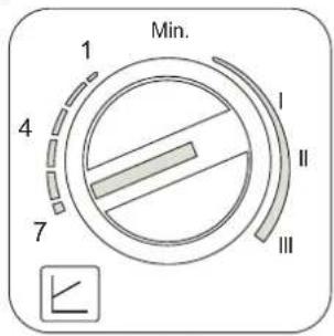
fig. 20
Setting
Fixed speed
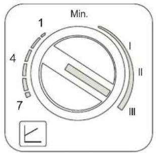
fig. 21
- Proportional Head Dp-v setting (fig. 20)
The circulating pump head will be automatically reduced with the decrease in flow rate required by the system. This setting is optimum for systems with radiators (2 pipes or single pipe) and/or thermostatic valves.
The strong points are the reduction in power consumption with the decrease in system demand and reduction of noise in radiators and/or thermostatic valves. The operating range is from min. (1) to max. (7).
- Setting Fixed speed (fig. 21)
The circulating pump does not modulate its power. The operating principle is that of conventional 3-speed circulating pumps (with a reduction in power consumption compared to them). The operating range goes from speed 1 (I) to speed 3 (III).
High-efficiency circulating pump (model PARA)
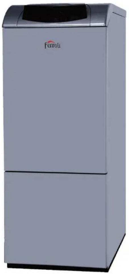
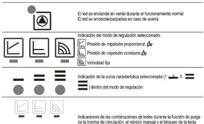
Control buttons and signaling LEDs
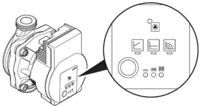
fig. 22

In normal operation, the LED lights up green
LED on flashing in case of a fault


Selected adjustment mode:

Constant head pc
Fixed speed


Selected characteristic curve (adjustment mode


Combined LED indications during circulating pump venting, manual restart and button lock


Press the button to set the various adjustment combinations
- Press for
3 seconds to activate circulating pump venting
- Press for
5 seconds for manual restart
- Press for
8 seconds to lock/unlock the button


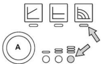
For a correct result of the "Thermal quantity balance" calculation (see section 11 THERMAL QUANTITY BALANCE (METERIN), the circulating pump must be set to "Constant speed") and to the position ○. To set this adjustment, press button "A" several times until the LEDs shown in the figure below light up.

flowchart
graph TD
    A["Input Data"] --> B["Processing"]
    B --> C["Output"]
    D["Data Collection"] --> E["Feedback Loop"]
    E --> F["Output"]
    style A fill:#f9f,stroke:#333
    style B fill:#f9f,stroke:#333
    style C fill:#f9f,stroke:#333
    style D fill:#ccf,stroke:#333
    style E fill:#cfc,stroke:#333
    style F fill:#fcc,stroke:#333
fig. 23
However, a different operating strategy can be set, depending on the characteristics of the system.
- Setting -v Proportional Head
The circulating pump head will be automatically reduced with the decrease in flow rate required by the system.
The strengths are reduced power consumption as the system demand decreases, and reduced noise. The operating range is from minimum to maximum.
- Setting A-c Constant Head
The circulating pump head is constant as the flow rate required by the system varies.
- Setting Fixed speed
The circulating pump does not modulate its power. The operating principle is that of conventional 3-speed circulating pumps (with a reduction in power consumption compared to them). The operating range is from speed 1 (.) to speed 3 (.).
ATLAS D ECO 30/42 K 100/130 UNIT
Water system characteristics
In the presence of water harder than 25^ Fr ( 1^ F = 10ppm CaCO _3 ), use suitably treated water in order to avoid possible scaling in the boiler. Treatment must not reduce the hardness to values below 15^ F (Decree 236/88 for uses of water intended for human consumption). Treatment of the water used is indispensable in case of very large systems or with frequent introduction of replenishing water in the system.

If water softeners are installed at the boiler cold water inlet, make sure not to reduce the water hardness too much, as this could cause early deterioration of the magnesium anode in the hot water tank.
Antifreeze system, antifreeze fluids, additives and inhibitors
The boiler is equipped with an antifreeze system that turns on the boiler in heating mode when the system delivery water temperature falls under 6^ C. The device will not come on if the electricity and/or gas supply to the unit are cut off. If it becomes necessary, it is permissible to use antifreeze fluid, additives and inhibitors only if the manufacturer of these fluids or additives guarantees they are suitable for this use and cause no damage to the heat exchanger or other components and/or materials of the boiler unit and system. It is prohibited to use generic antifreeze fluid, additives or inhibitors that are not expressly suited for use in heating systems and compatible with the materials of the boiler unit and system.
3.4 Burner connection
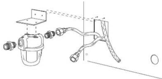
The burner is equipped with flexible pipes and a filter for connection to the oil feed line. Run the flexible pipes out of the back and install the filter as indicated in fig. 24.
natural_image
Technical line drawing of a spray gun assembly with no visible text or symbolsfig. 24 - Fuel filter installation
The oil feed circuit must be made according to one of the following diagrams, without exceeding the pipe lengths (LMAX) given in the table.
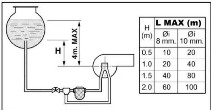
fig. 25 - Gravity feed
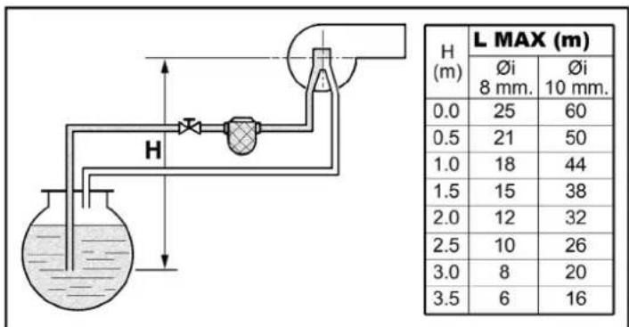
fig. 26 - Suction feed
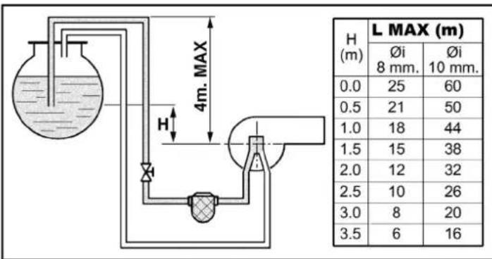
fig. 27 - Siphon feed
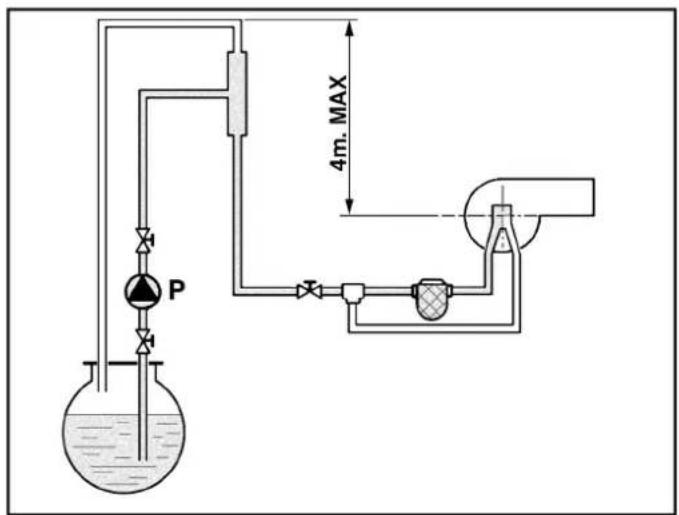
fig. 28 - Ring feed
3.5 Electrical connections
Connection to the electrical grid

The unit's electrical safety is only guaranteed when correctly connected to an efficient earthing system executed according to current safety standards. Have the efficiency and suitability of the earthing system checked by professionally qualified personnel. The manufacturer is not responsible for any damage caused by failure to earth the system. Also make sure that the electrical system is adequate for the maximum power absorbed by the unit, as specified on the boiler dataplate.
The boiler is prewired and provided with a Y-cable and plug for connection to the electricity line. The connections to the grid must be made with a permanent connection and equipped with a bipolar switch whose contacts have a minimum opening of at least 3 mm, interposing fuses of max. 3A between the boiler and the line. It is important to respect the polarities (LINE: brown wire / NEUTRAL: blue wire / EARTH: yellow-green wire) in making connections to the electrical line. During installation or when changing the power cable, the earth wire must be left 2 cm longer than the others.

The user must never change the unit's power cable. If the cable gets damaged, switch off the unit and have it changed solely by professionally qualified personnel. If changing the electric power cable, use solely "HAR H05VV-F" 3x0.75 mm2 cable with a maximum outside diameter of 8 mm.
Room thermostat (optional)

IMPORTANT: THE ROOM THERMOSTAT MUST HAVE VOLTAGE-FREE CONTACTS. CONNECTING 230 V TO THE ROOM THERMOSTAT TERMINALS WILL PERMANENTLY DAMAGE THE ELECTRONIC BOARD.
When connecting time controls or a timer, do not take the power supply for these devices from their breaking contacts Their power supply must be by means of direct connection from the mains or with batteries, depending on the kind of device.
Accessing the electrical terminal block
Undo the two screws "A" located on the top part of the control panel and remove the cover.
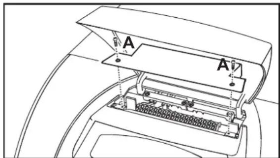
fig. 29 - Accessing the terminal board
3.6 Connection to the flue
The unit must be connected to a flue designed and built in compliance with the current regulations. The pipe between the boiler and flue must be made from material suitable for the purpose, i.e. heat and corrosion resistant. Ensure the seal at the joints.
4. SERVICE AND MAINTENANCE
All adjustment, conversion, commissioning and maintenance operations described below must only be carried out by Qualified Personnel (meeting the professional technical requirements of current regulations) such as the personnel of the Local After-Sales Technical Service.
FERROLI declines any liability for damage and/or injury caused by unqualified and unauthorised persons tampering with the unit.
4.1 Adjustments
TEST mode activation
Press the heating buttons (details 3 and 4 - fig. 1) together for 5 seconds to activate the TEST mode. The boiler switches on irrespective of the system or DHW request.
The healing symbol (detail 24 - fig. 1) and DHW symbol (detail 12 - fig. 1) flash on the display.
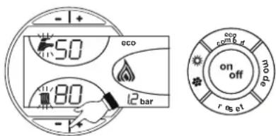
fig. 30 - TEST mode
To deactivate the Test mode, repeat the activation sequence.
The TEST mode is automatically disabled in any case after 15 minutes.
Burner adjustment
The burner is factory-set as given in table 2. The burner can be set to a different output by acting on the pump pressure, nozzle, head adjustment, and air adjustment as per the following paragraphs. In any case, the new adjusted output must fall within the boiler's nominal operating range. After making any adjustments, using a combustion analyser check that the CO_2 content in the fumes is between 11% and 12% .
Nozzle flow rate table for oil
table 2 gives the oil flow rates (in kg/h) according to the change in pump pressure and nozzles.
N.B. - The values given below are only approximate, since nozzle flow rates can vary by ±5% . Also, with burners having a preheater, the fuel flow rate decreases by about 10%.
Table. 2
| Pump pressure (bar) | |||||||
| NOZZLE G.P.H. | 8 9 10 | 11 12 13 14 | |||||
| 0.40 | 1,32 1,40 | 1,47 1,54 1,61 | 1,68 1,75 | ||||
| 15,66 16,50 | 17,43 18,26 | 19,09 19,92 | 20,75 | ||||
| 0.50 | 1,57 1,65 | 1,73 1,81 1,89 | 1,97 2,05 | ||||
| 18,62 19,57 | 20,51 21,50 | 22,42 23,36 | 24,31 | ||||
| 0.60 | 1,93 2,01 | 2,23 2,32 2,42 | 2,52 2,64 | ||||
| 22,89 23,83 | 26,44 27,51 | 28,70 29,88 | 31,31 | ||||
| 0.65 | 2,12 2,25 | 2,40 2,63 2,74 | 2,80 2,91 | ||||
| 25,14 26,58 | 28,46 31,19 | 32,49 33,21 | 34,51 | ||||
| 0.75 | 2,50 2,65 | 2,80 2,95 3,07 | 3,20 3,33 | ||||
| 29,65 31,43 | 33,21 34,99 | 36,41 37,95 | 39,49 | ||||
| 0.85 | 2,92 3,10 | 3,27 3,45 3,60 | 3,75 3,90 | ||||
| 34,63 36,76 | 38,78 40,92 | 42,69 44,47 | 46,25 | ||||
| 1.00 | 3,30 3,50 | 3,67 3,85 4,02 | 4,20 4,38 | ||||
| 39,13 41,51 | 43,52 45,66 | 47,67 48,72 | 51,95 | ||||
| 1.25 | 4,12 4,40 | 4,61 4,82 5,08 | 5,25 5,46 | ||||
| 48,86 52,18 | 54,67 57,16 | 59,65 62,26 | 64,75 | ||||
| 1.50 | 4,95 5,30 | 5,55 5,80 6,05 | 6,30 6,55 | ||||
| 58,70 62,85 | 65,82 68,78 | 71,75 74,72 | 77,68 | ||||
| 1.75 | 5,69 6,18 | 6,46 6,75 7,06 | 7,38 7,96 | ||||
| 67,48 73,29 | 76,61 80,05 | 83,73 87,53 | 91,20 | ||||
| Flow rate at nozzle outlet in kg/h | |||||||
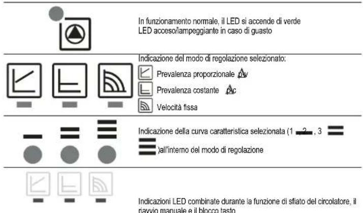
Pump pressure adjustment
The pump is factory-set to 12 bar. Use an oil bath gauge to check the pressure. The pressure can be adjusted between 11 and 14 bar.
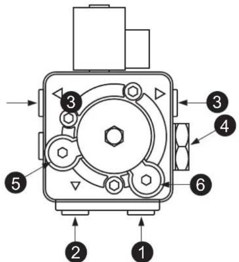
fig. 31- Pump ITALPUMP

fig. 32- Pump DANFOSS
- Suction ∅1/4"
- Return ∅1/4"
- Oil delivery ∅1/8"
- Pressure adjustment
- Pressure gauge connection ∅1/8"
- Vacuum gauge connection ∅1/8"
Combustion head adjustment
The head is adjusted by means of the screw 1, according to the indications of the pointer 2.
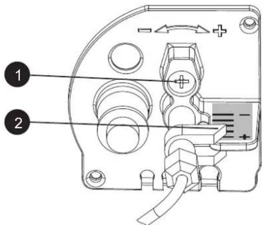
fig. 33
Air damper adjustment
After loosening the screw 3, operating the screw 1, the combustion air is adjusted according to the indications of the pointer 2. After adjustment, lock the screw 3.
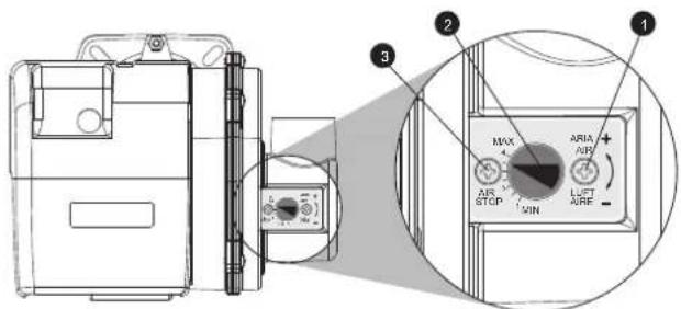
fig. 34
Position of electrodes - baffle
After fitting the nozzle, check correct positioning of the electrodes and baffle, according to the dimensions given below. It is advisable to check the dimensions after each operation on the head.
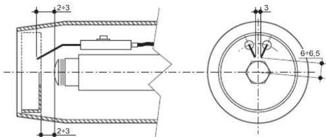
fig. 35- Position of electrodes - baffle
4.2 Commissioning
⚠️ Checks to be done at first lighting, and after all maintenance operations that involved disconnection from the systems or work on safety devices or parts of the boiler:
Before lighting the boiler
- Open any on-off valves between the boiler and the systems.
- Check the tightness of the fuel system.
- Check the pre-filling of the expansion tank
- Fill the water system and make sure that all air contained in the boiler and the system has been vented by opening the air vent valve on the boiler and any vent valves on the system.
- Make sure there are no water leaks in the system, hot water circuits, connections or boiler.
- Make sure the electrical system is properly connected and the earth system works properly.
- Make sure there are no flammable liquids or materials in the immediate vicinity of the boiler.
- Fit the pressure gauge and the vacuum gauge on the pump (remove after starting) of the burner.
- open the gate valves along the diesel pipe
Lighting
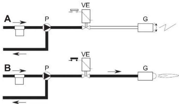
flowchart
graph TD
    A["Component A"] --> P1["P"]
    P1 --> VE1["VE"]
    VE1 --> G1["G"]
    B["Component B"] --> P2["P"]
    P2 --> VE2["VE"]
    VE2 --> G2["G"]
    P1 -->|Downward Arrow| P2
    P2 -->|Upward Arrow| P1
    G1 -->|Downward Arrow| G2
    G2 -->|Downward Arrow| G1
fig. 36 - Starting
A
When the thermostatic line closes, the burner motor starts turning together with the pump: all the oil sucked is sent to the return. The burner blower and the ignition transformer are also working, therefore the following stages are carried out:
- firebox prevention.
• prewash of a part of the oil circuit. - preignition, with discharge between electrode tips.
B
At the end of prewash, the unit opens the electromagnetic valve: the oil reaches the nozzle, where it is finely sprayed.
Its contact with the discharge between the electrode tips creates the flame.
The safety time begins simultaneously.
Unit cycle
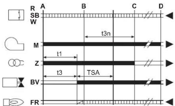
fig. 37 - Unit cycle
R-SB-W Thermostats/Pressure switches
M Burner motor
Z Ignition transformer
BV Electromagnetic valve
FR Photoresistance
A' Beginning of ignition with pre-heater
A Beginning of ignition without pre-heater
B Flame present
C Normal operation
D Adjustment stop (TA-TC)
t1 Pre-ventilation time
TSA Safety time
t3 Pre-ignition time
t3n Post-ignition time
tw Preheating time

Output signals from the unit
Necessary input signals
Checks during operation
- Ignite the appliance as described in sec. 2.3.
- Check that the fuel circuit and water systems are airtight.
- Check the efficiency of the flue and air-fume ducts while the boiler is working.
- Check that the water is circulating properly between the boiler and the systems.
- Check the proper ignition of the boiler by performing various tests, turning it on and off with the room thermostat or remote control.
- Check that the burner door and fume chamber are tight.
- Check that the burner works properly.
- Analyse the combustion (with the boiler unit stable) and check that the content of CO_2 in the fumes is between 11% and 12% .
- Check the parameters are programmed correctly and perform any required customization (compensation curve, power, temperatures, etc.).
4.3 Maintenance
Periodical check
To ensure proper operation of the unit, have it checked yearly by qualified personnel, providing for the following:
• The control and safety devices must function correctly.
• The fume exhaust circuit must be perfectly efficient.
- Make sure there are no obstructions or dents in the fuel supply and return pipes.
- Clean the fuel intake line filter.
- Check correct fuel consumption
- Clean the combustion head in the fuel outlet zone, on the turbulence disc.
- Leave the burner operating at max. for about ten minutes, then analyse the combustion, checking:
- Correct setting of all the elements specified in this manual
- Fume temperatures at the flue
- CO2 percentage content
• The ducts must be free of obstructions and leaks
• The burner and exchanger must be clean and free of deposits. For cleaning, do not use chemical products.
• The fuel and water systems must be tight.
- The water pressure in the system when cold must be approx. 1 bar; otherwise bring it to that value.
• The circulating pump must not be blocked.
• The expansion tank must be filled.
- Check the magnesium anode and replace it if necessary.

The boiler casing, control panel and aesthetic parts can be cleaned with a soft and damp cloth, if necessary soaked in soapy water. Do not use any abrasive detergents and solvents.
Accessing the electrode and nozzle
- Disconnect the transformer electrode cables and remove the photoresistance 1, and the union 2 connecting the oil pipe to line 3 of the nozzle. Loosen the screws 4 and pull out the nozzle-baffle-electrode flange assembly.
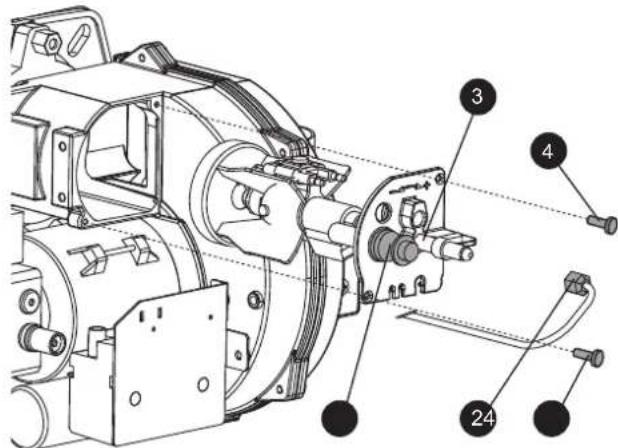
fig. 38
- Undo the screw 5 to remove the baffle and screw 6 to remove the electrodes. Proper cleaning of the nozzle is obtained by removing the filter and cleaning the slots and spraying hole with petrol, rinsing it with fuel oil. When reassembling everything, pay attention to the correct positioning of the electrodes-baffle.
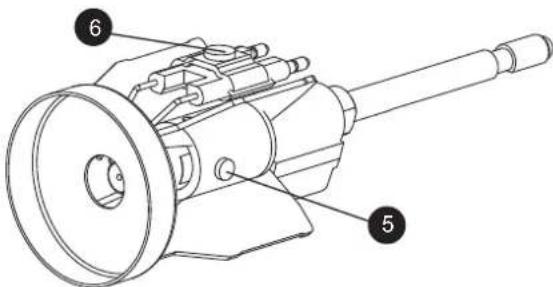
fig. 39
Boiler cleaning
- Disconnect the power supply to the boiler.
- Remove the burner (see preceding section).
- Remove the upper panel.
- Remove the cleaning door "A" by undoing the nuts "B".
- Open the burner door "C" after undoing the nuts "D".
- Clean the inside of the boiler and the entire path of exhaust fumes, using a tube brush, exhauster or compressed air.
- Then close the doors.
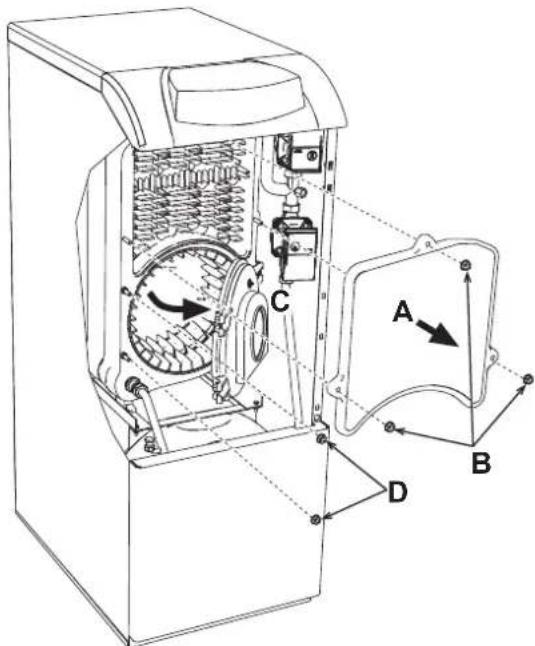
fig. 40
4.4 Troubleshooting
Diagnostics
The boiler is equipped with an advanced self-diagnosis system. In case of a boiler fault, the display will flash together with the fault symbol (detail 22 - fig. 1) indicating the fault code.
There are faults that cause permanent shutdowns (marked with the letter "A"): to restore operation, press the RESET button (detail 8 - fig. 1) for 1 second or use the RESET on the remote timer control (optional) if installed; if the boiler does not restart it is necessary to eliminate the fault indicated in the operation LEDs.
Other faults cause temporary shutdowns (marked with the letter "F") which are automatically reset as soon as the value returns within the boiler's normal working range.
Table. 3 - List of faults
| Fault code | Fault Possible cause | Cure | |
| A01 | Burner block | Pump blocked Replace | |
| Faulty electric motor Replace | |||
| Faulty oil valve Replace | |||
| No fuel in tank, or water on bottom Refill with fuel or suck the water | |||
| Oil line feed valves closed Open | |||
| Dirty filters (line-pump-nozzle) Clean | |||
| Pump unprimed Prime and find the cause of unprim-ing | |||
| Ignition electrodes not properly adjusted, or dirty | Adjust or clean them | ||
| Nozzle clogged, dirty or deformed Replace | |||
| Unsuitable head and shutter adjustments Adjust | |||
| Faulty electrodes or earthed Replace | |||
| Faulty ignition transformer Replace | |||
| Faulty electrode wires or earthed | Replace | ||
| Electrode wires deformed by high temper-ature | Replace and protect | ||
| Faulty valve or transformer electrical con-nections | Check | ||
| Broken pump-motor joint | Replace | ||
| Pump inlet connected to return pipe | Correct the connection | ||
| Faulty photoresistance | Replace | ||
| Dirty photoresistance | Clean the photoresistance | ||
| A02 | Flame present signal with burner off | Photoresistance short circuit | Replace the photoresistance |
| Extraneous light strikes the photoresis-ance | Eliminate the light source | ||
| A03 | Overtemperature pro-tection activation | Heating sensor damaged | Check the correct positioning and operation of the heating sensor |
| No water circulation in the system | Check the circulating pump (See table table 4) | ||
| Air in the system | Vent the system | ||
| A04 | Card parameter fault | Wrong card parameter setting | Check the card parameter and mod-ify it if necessary |
| F07 | Prehealer fault (the contact does not close in 120 seconds) | Wiring disconnected Check the wiring | |
| F09 | Card parameter fault | Wrong card parameter setting | Check the card parameter and mod-ify it if necessary |
| F10 | Delivery sensor 1 fault | Sensor damaged | Check the wiring or replace the sen-sor |
| Wiring shorted | |||
| Wiring disconnected | |||
| F11 | DHW sensor fault | Sensor damaged | Check the wiring or replace the sen-sor |
| Wiring shorted | |||
| Wiring disconnected | |||
| F12 | Card parameter fault | Wrong card parameter setting | Check the card parameter and mod-ify it if necessary |
| F14 | Delivery sensor 2 fault | Sensor damaged | Check the wiring or replace the sen-sor |
| Wiring shorted | |||
| Wiring disconnected | |||
| F16 | Card parameter fault | Wrong card parameter setting | Check the card parameter and mod-ify it if necessary |
| F34 | Supply voltage under 170V. | Electric mains trouble | Check the electrical system |
| F35 | Faulty mains frequency | Electric mains trouble | Check the electrical system |
| F37 | Incorrect system water pressure | Pressure too low | Fill the system |
| Sensor damaged | Check the sensor | ||
| F39 | External probe fault | Probe damaged or wiring shorted | Check the wiring or replace the sen-sor |
| Probe disconnected after activating the sliding temperature | Reconnect the external sensor or disable the sliding temperature | ||
| F40 | Incorrect system water pressure | Pressure too high | Check the system |
| Check the safety valve | |||
| Check the expansion tank | |||
| A41 | Sensor positioning | Delivery sensor not inserted in boiler shell | Check the correct positioning and operation of the heating sensor |
| F42 | Heating sensor fault | Sensor damaged | Replace the sensor |
| F47 | System water pressure sensor fault | Wiring disconnected Check the wiring | |
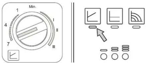
Circulating pumsp diagnostics
Some faults linked to the circulating pump are signalled by the LED located around the speed selector (fig. 41 - fig. 42).
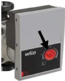
fig. 41
Table. 4 - Circulating pump LED indications
 | OffCirculating pump on STANDBY |
 | Green ONCirculating pump Working |
 | Green FlashingAir venting cycle |
 | Green/Red alternatingCirculating pump blocked due to external causes:- Overvoltage (>270V)- Insufficient voltage (<160V)- Motor overload |
 | Red FlashingCirculating pump blocked due to internal causes:- Motor blocked- Damaged electronics |
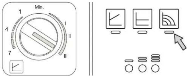
Circulating pump diagnostics (model PARA)
Some faults linked to the circulating pump are signaled by the LED (fig. 42).
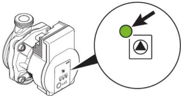
fig. 42
| LED | Fault | Cause | Cure |
| On with red light | Fault | Blocked rotor | Activate manual restart or contact Customer Service |
| Contact/winding | Faulty winding | ||
| Flashing with red light | Under/overvoltage | Supply side voltage too low/high | Check the mains voltage and conditions of use.Request Customer Service |
| Excessive module temperature | Inside of module too hot | ||
| Short circuit | Motor current too high | ||
| Flashing with red/green light | Turbine operation | The hydraulic system of pumps is fed but the pump does not have mains voltage | Check the mains voltage, the water flow/pressure as well as the environmental conditions |
| Dry running | Air in pump | ||
| Overload | The motor turns with difficulty. Pump operation not in accordance with specifications (e.g. high module temperature). The speed is lower than in normal operation. |
5. TECHNICAL DATA AND CHARACTERISTICS
Key of figures cap. 5
A Safety and non-return valve
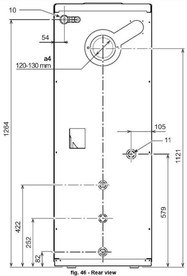
A4 Fume outlet
10 System delivery - ∅ 3/4"
11 System return - ∅ 1'
14 Heating safety valve
32 Heating circulating pump
36 Automatic air vent
130 Hot water tank circulating pump
143 Hot water tank control thermostat
154 Condensate drain pipe
178 Hot water tank thermometer bulb
179 Non-return valve
180 Hot water tank
192 Recirculation - ∅ 3/4"
197 Manual air vent
209 Hot water tank delivery - ∅ 3/4"
210 Hot water tank return - ∅ 3/4"
233 Hot water tank drain cock
246 Pressure transducer
275 Heating system drain cock
278 Double sensor (Heating + Safety)
293 Hot water tank inspection flange
295 Burner
5.1 Dimensions, connections and main components
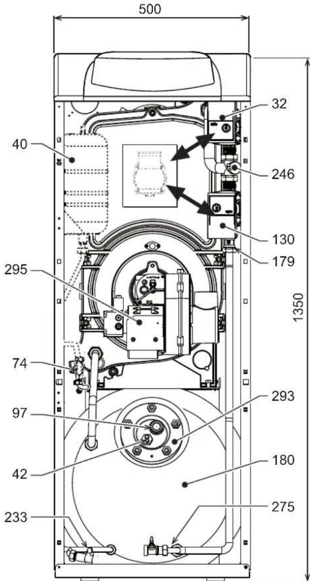
fig. 43 - Front view
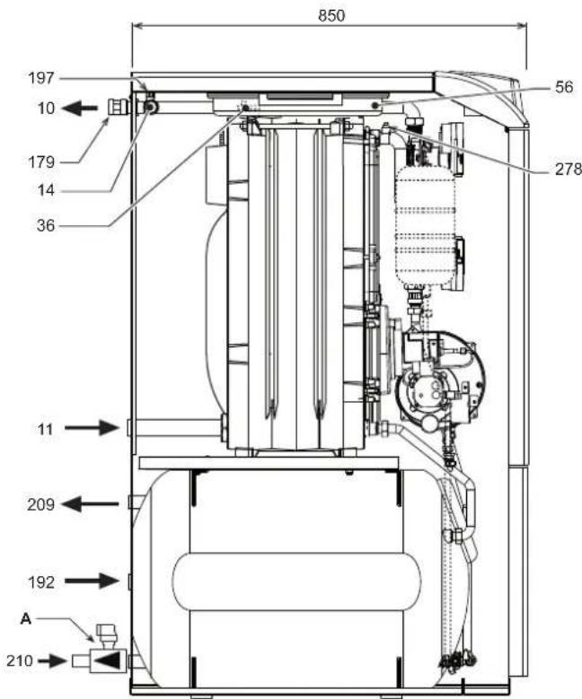
fig. 44 - Side view - ATLAS D ECO 42 K 130 UNIT
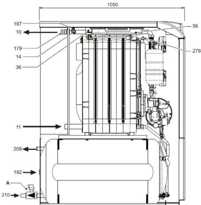
fig. 45 - Side view - ATLAS D ECO 42 K 130 UNIT
5.2 Hydraulic circuit

fig. 47 - Hydraulic circuit
5.3 Diagrams
Circulating pumps Head/Pressure loss
- Circulating pump head with setting at "fixed speed".
H [m H2O]
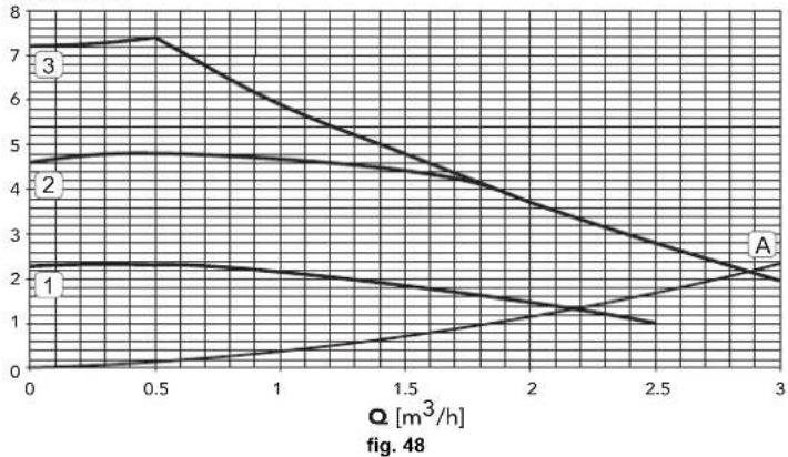
line
| Q [m³/h] | Curve 1 | Curve 2 | Curve 3 | | -------- | ------- | ------- | ------- | | 0 | 2.5 | 4.5 | 7.0 | | 0.5 | 2.4 | 4.6 | 7.5 | | 1.0 | 2.3 | 4.5 | 6.5 | | 1.5 | 2.2 | 4.4 | 5.5 | | 2.0 | 2.1 | 4.2 | 4.5 | | 2.5 | 2.0 | 4.0 | 3.5 | | 3.0 | 2.0 | 3.8 | 2.5 |A Boiler pressure losses
1 - 2 - 3 Circulating pump speed
- Circulating pump head with setting at "proportional head".
A Boiler pressure losses
5.4 Technical data table
| Model ATLAS D ECO 30 K 100 UNIT ATLAS D ECO 42 K 130 UNIT | ||||
| Number of elements no. 3 3 | ||||
| Max. heating capacity (Hs) kW 28.3 41.9 (Q) | ||||
| Max. heating capacity (Hi) kW 26.6 39.4 | ||||
| Min. heating capacity (Hs) kW 22.4 22.3 (Q) | ||||
| Min. heating capacity (Hi) kW 21.1 21.0 | ||||
| Max. heat output in heating (80-60°C) kW 25.0 37.0 (P) | ||||
| Min. heat output in heating (80-60°C) kW 20.0 20.0 (P) | ||||
| Max. heating capacity in DHW (Hs) | kW | 28.3 42.0 (Q) | ||
| Max. heating capacity in DHW (Hi) | kW | 26.6 39.4 | ||
| Min. heating capacity in DHW (Hs) | kW | 22.4 22.4 (Q) | ||
| Min. heating capacity in DHW (Hi) | kW | 21.0 21.0 | ||
| Max. heat output in DHW (80-60°C) | kW | 25.0 37.0 (P) | ||
| Min. heat output in DHW (80-60°C) | kW | 20.0 20.0 (P) | ||
| Efficiency Pmax (80-60°C) (Hs) | % | 88.2 88.3 | ||
| Efficiency Pmax (80-60°C) (Hi) | % | 93.9 94.0 | ||
| Efficiency Pmin (80-60°C) (Hs) | % | 89.1 89.7 | ||
| Efficiency Pmin (80-60°C) (Hi) | % | 94.9 95.5 | ||
| Efficiency 30% (Hs) | % | 92.2 91.5 | ||
| Efficiency 30% (Hi) | % | 98.2 97.4 | ||
| Max. working pressure in heating | bar | 6 6 (PMS) | ||
| Min. working pressure in heating | bar | 0.8 | 0.8 | |
| Max. heating temperature | °C | 110 | 110 | (tmax) |
| Heating water content | liters | 21 | 26 | |
| Heating expansion vessel capacity | liters | 10 | 10 | |
| Heating expansion vessel prefilling pressure | bar | 1 1 | ||
| Max. working pressure in DHW | bar | 9 9 (PMW) | ||
| Min. working pressure in DHW | bar | 0.1 | 0.1 | |
| Hot water tank content | liters | 90 | 117 | |
| DHW expansion vessel capacity | liters | 4 3 | ||
| DHW flow rate Dt 30°C | l/10min | 195 | 250 | |
| DHW flow rate Dt 30°C | l/h | 750 | 850 | |
| Protection rating | IP | XOD XOD | ||
| Power supply voltage | V/Hz | 230/50 | 230/50 | |
| Electrical power input in heating | W | 195 | 195 | |
| Electrical power input in DHW | W | 195 | 195 | |
| Empty weight | kg | 225 | 265 | |
| Combustion chamber length | mm | 350 | 450 | |
| Combustion chamber diameter | mm | 300 | 300 | |
| Pressure loss on fume side | mbar | 0.11 | 0.35 | |
ErP product fiche
MODEL: ATLAS D ECO 30 K 100 UNIT - (OLHU3YWA)
| Trademark: FERROLI | |||
| Condensing boiler: NO | |||
| Low-temperature boiler (**): YES | |||
| B1 Boiler: NO | |||
| Combination heater: YES | |||
| Cogeneration space heater: NO | |||
| Item | Symbol | Unit | Value |
| Seasonal space heating energy efficiency class (from A+++ to D) | B | ||
| Rated heat output | Pn | kW | 25 |
| Seasonal space heating energy efficiency | _s | % | 86 |
| Useful heat output | |||
| Useful heat output at rated heat output and high-temperature regime (*) | P4 | kW | 25,0 |
| Useful heat output at 30% of rated heat output and low-temperature regime (**) | P1 | kW | 7,8 |
| Useful efficiency | |||
| Useful efficiency at rated heat output and high-temperature regime (*) | _4 | % | 88,2 |
| Useful efficiency at 30% of rated heat output and low-temperature regime (**) | _1 | % | 92,2 |
| Auxiliary electricity consumption | |||
| At full load | elmax | kW | 0,150 |
| At part load | elmin | kW | 0,069 |
| In standby mode | PSB | kW | 0,003 |
| Other items | |||
| Standby heat loss | Pstby | kW | 0,105 |
| Ignition burner power consumption | Pign | kW | 0,000 |
| Annual energy consumption | QHE | GJ | 83 |
| Sound power level | LWA | dB | 62 |
| Emissions of nitrogen oxides | NOx | mg/kWh | 95 |
| For combination heaters | |||
| Declared load profile | XL | ||
| Water heating energy efficiency class (from A+ to F) | B | ||
| Daily electricity consumption | Qelec | kWh | 0,279 |
| Annual electricity consumption | AEC | kWh | 55 |
| Water heating energy efficiency | _wh | % | 64 |
| Daily fuel consumption | Qfuel | kWh | 31,807 |
| Annual fuel consumption | AFC | GJ | 24 |
(*) High-temperature regime means 60°C return temperature at heater inlet and 80°C feed temperature at heater outlet.
(**) Low temperature means for condensing boilers 30°C, for low-temperature boilers 37°C and for other heaters 50°C return temperature (at heater inlet).
ErP product fiche
MODEL: ATLAS D ECO 42 K 130 UNIT - (OLHU4YWA)
| Trademark: FERROLI | |||
| Condensing boiler: NO | |||
| Low-temperature boiler (**): YES | |||
| B1 Boiler: NO | |||
| Combination heater: YES | |||
| Cogeneration space heater: NO | |||
| Item | Symbol | Unit | Value |
| Seasonal space heating energy efficiency class (from A+++ to D) | B | ||
| Rated heat output | Pn | kW | 37 |
| Seasonal space heating energy efficiency | _s | % | 86 |
| Useful heat output | |||
| Useful heat output at rated heat output and high-temperature regime (*) | P4 | kW | 37,1 |
| Useful heat output at 30% of rated heat output and low-temperature regime (***) | P1 | kW | 11,5 |
| Useful efficiency | |||
| Useful efficiency at rated heat output and high-temperature regime (*) | _4 | % | 88,3 |
| Useful efficiency at 30% of rated heat output and low-temperature regime (***) | _1 | % | 91,5 |
| Auxiliary electricity consumption | |||
| At full load | elmax | kW | 0,150 |
| At part load | elmin | kW | 0,068 |
| In standby mode | PSB | kW | 0,003 |
| Other items | |||
| Standby heat loss | Pstby | kW | 0,127 |
| Ignition burner power consumption | Pign | kW | 0,000 |
| Annual energy consumption | QHE | GJ | 123 |
| Sound power level | LWA | dB | 62 |
| Emissions of nitrogen oxides | NOx | mg/kWh | 92 |
| For combination heaters | |||
| Declared load profile | XXL | ||
| Water heating energy efficiency class (from A+ to F) | B | ||
| Daily electricity consumption | Qelec | kWh | 0,317 |
| Annual electricity consumption | AEC | kWh | 70 |
| Water heating energy efficiency | _wh | % | 61 |
| Daily fuel consumption | Qfuel | kWh | 37,231 |
| Annual fuel consumption | AFC | GJ | 31 |
(*) High-temperature regime means 60°C return temperature at heater inlet and 80°C feed temperature at heater outlet.
(**) Low temperature means for condensing boilers 30°C, for low-temperature boilers 37°C and for other heaters 50°C return temperature (at heater inlet).
5.5 Wiring diagram
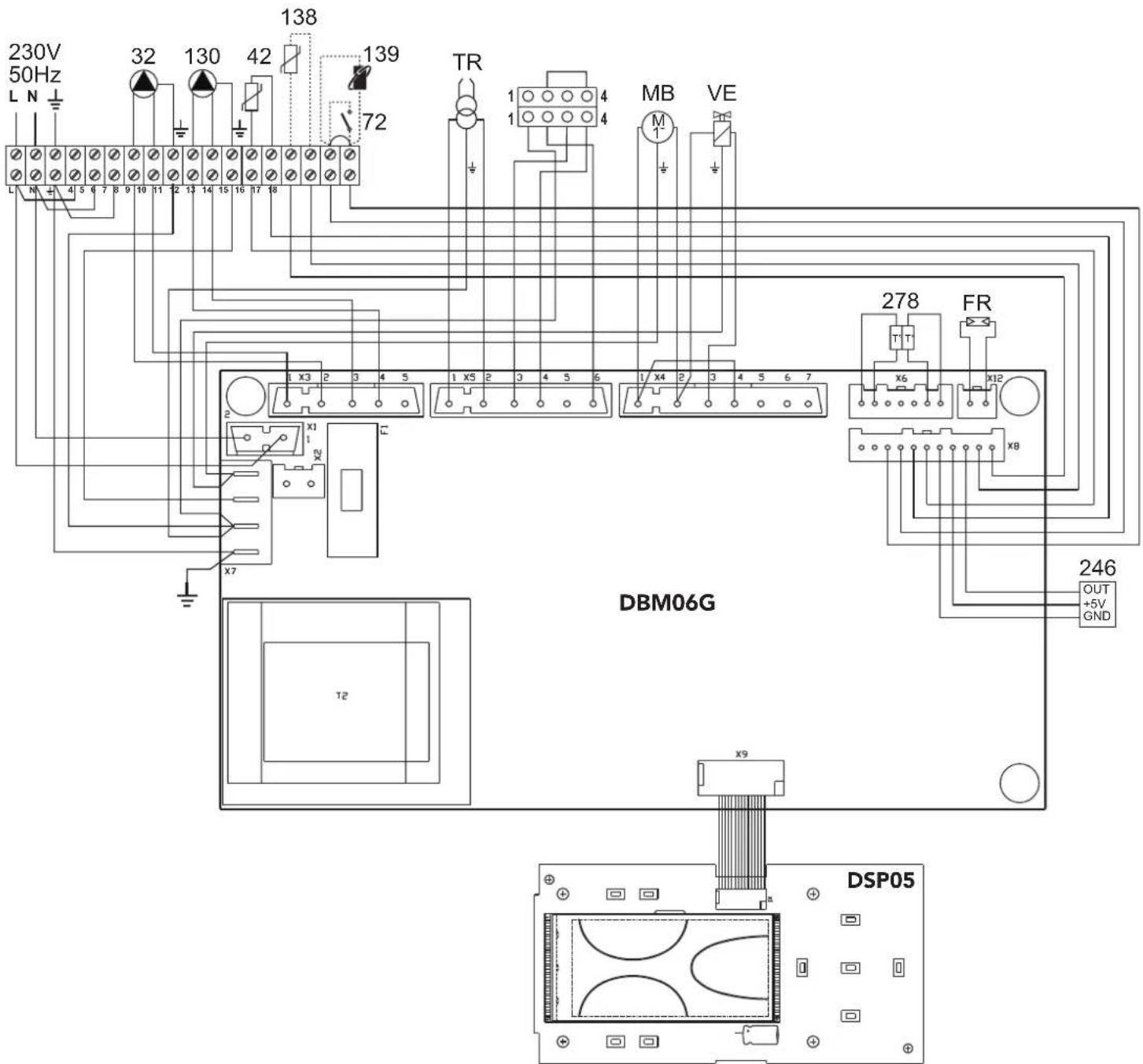
fig. 50 - Wiring diagram
32 Heating circulating pump
42 DHW temperature probe
72 Room thermostat (optional)
130 Hot water tank circulating pump
138 External probe (optional)
139 Remote Timer Control (optional)
246 Pressure transducer
278 Double sensor (Safety + Heating)
TR Ignition transformer
FR Photoresistance
MB Burner motor
VE Electromagnetic valve
FR
1. CONSIGNES GÉNÉRALES
fig. 2
fig. 7
fig. 8
fig. 9
fig. 10
line
| X-axis | Y-axis | |---|---| | 20 | 30 | | 10 | 35 | | -10 | 40 | | -20 | 45 | | 0 | 50 | | 10 | 55 | | 20 | 60 | | 30 | 65 | | 40 | 70 | | 50 | 75 | | 60 | 80 | | 70 | 85 | | 80 | 90 | | 90 | 95 | | 100 | 100 | The chart displays a single data series with values labeled as '1' through '7'. The x-axis ranges from -20 to 20 and the y-axis ranges from 20 to 90.fig. 13 - Courbes de compensation
line
| x | y | |----|------| | 0 | 0 | | -10| 10 | | -20| 20 |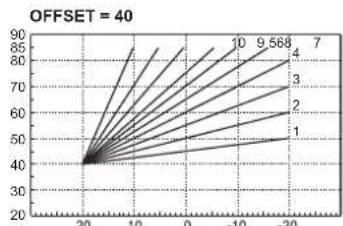
line
| x | y | | ---- | ---- | | 20 | 40 | | 10 | 50 | | 0 | 60 | | -10 | 70 | | -20 | 80 |natural_image
Technical line drawing of a mechanical device with control panel and display icons, no readable text or symbols present.fig. 22

natural_image
Technical line drawing of a mechanical assembly with hoses and a central component (no text or symbols)fig. 24 - Installation filtre combustible
fig. 31- Pompe ITALPUMP

fig. 32- Pompe DANFOSS
fig. 33
fig. 34
fig. 38
fig. 39
fig. 40
4.4 Dépannage
Diagnostic
fig. 42
line
| Q [m³/h] | Line 1 | Line 2 | Line 3 | | -------- | ------ | ------ | ------ | | 0 | 2.3 | 4.8 | 7.3 | | 0.5 | 2.2 | 4.9 | 7.5 | | 1.0 | 2.1 | 4.7 | 6.8 | | 1.5 | 2.0 | 4.5 | 5.8 | | 2.0 | 1.8 | 4.2 | 4.8 | | 2.5 | 1.5 | 3.8 | 3.8 | | 3.0 | 1.2 | 3.5 | 2.8 |MODÈLE: ATLAS D ECO 30 K 100 UNIT - (OLHU3YWA)
1. ALGEMENE WAARSCHUWINGEN
12 = Symbol warm sanitair water
15 = Aanduiding modus Eco (Economy) of Comfort
24 = Symbol verwarming
fig. 2
Sanitair water (Comfort)
fig. 3
Uitschakeling boiler (economy)
fig. 5 - Aanzetten verwarmingsketel
fig. 6 - Uitschakelen verwarmingsketel
fig. 9
fig. 22

flowchart
graph TD
    A["Computer monitor 1"] --> B["Computer monitor 2"]
    B --> C["Computer monitor 3"]
    C --> D["Arrow pointing to the circle labeled 'A'"]
    D --> E["Arrow pointing to a stack of coins on the circle"]
    style A fill:#f9f,stroke:#333
    style B fill:#f9f,stroke:#333
    style C fill:#f9f,stroke:#333
    style D fill:#f9f,stroke:#333
fig. 23
natural_image
Technical line drawing of a mechanical assembly with hoses and a central component (no text or symbols)fig. 24 - Installatie brandstofffilter
fig. 31- Pomp ITALPUMP
fig. 32- Pomp DANFOSS
fig. 33
fig. 34
fig. 38
fig. 39
fig. 40
natural_image
Technical diagram of a mechanical device with an inset showing a green circle and a black arrow pointing to a green circle containing a triangle symbol (no text or labels present)fig. 42
line
| Q [m³/h] | Line 1 | Line 2 | Line 3 | | -------- | ------ | ------ | ------ | | 0 | 2.3 | 4.7 | 7.3 | | 0.5 | 2.2 | 4.6 | 7.4 | | 1.0 | 2.0 | 4.5 | 6.5 | | 1.5 | 1.8 | 4.3 | 5.5 | | 2.0 | 1.5 | 4.0 | 4.5 | | 2.5 | 1.2 | 3.5 | 3.5 | | 3.0 | 1.0 | 2.5 | 2.5 |εικ. 9
natural_image
Technical line drawing of a mechanical device with a magnified inset showing its control panel (no text or symbols present)εικ. 2 2
natural_image
Technical line drawing of a spray gun assembly with hoses and a container (no text or symbols)εικ. 3 3
Ρύθμιση τάμπερ αέρα
εικ. 34
εΙΚ. 38
εικ. 39
Καθαρισμός λέβητα
εικ. 40
εικ. 4 2
line
| Q [m³/h] | Line 1 | Line 2 | Line 3 | | -------- | ------ | ------ | ------ | | 0 | 2.2 | 4.5 | 7.5 | | 0.5 | 2.1 | 4.4 | 7.3 | | 1.0 | 2.0 | 4.3 | 6.5 | | 1.5 | 1.8 | 4.2 | 5.5 | | 2.0 | 1.5 | 4.0 | 4.5 | | 2.5 | 1.2 | 3.5 | 3.5 | | 3.0 | 1.0 | 3.0 | 2.5 |
- ATLAS D ECO 30/42 K 100/130 UNIT
- CE
- IT
- AVVERTENZE GENERALI
- THE CE MARKING CERTIFIES THAT THE PRODUCTS MEET THE ESSENTIAL REQUIREMENTS OF
- THE RELEVANT DIRECTIVES IN FORCE. THE DECLARATION OF CONFORMITY MAY BE REQUESTED FROM THE MANUFACTURER.
- OPERATING INSTRUCTIONS
- Introduction
- Control panel
- Panel key
- Indication during operation
- Heating
- DHW (Comfort)
- Exclude hot water tank (economy)
- Lighting and turning off
- Boiler lighting
- Turning the boiler off
- Adjustments
- Summer/Winter Switchover
- Heating temperature setting
- DHW temperature adjustment
- Room temperature adjustment (with optional room thermostat)
- Room temperature adjustment (with optional remote timer control)
- Sliding temperature
- Compensation curve and curve offset
- Adjustments from Remote Timer Control
- System water pressure adjustment
- Optional filling cock and vessel kit
- INSTALLATION
- General Instructions
- Place of installation
- Plumbing connections
- Important
- High efficiency hot water tank circulating pump
- High efficiency heating circulating pump
- - Proportional Head Dp-v setting (fig. 20)
- - Setting Fixed speed (fig. 21)
- High-efficiency circulating pump (model PARA)
- - Setting -v Proportional Head
- - Setting A-c Constant Head
- - Setting Fixed speed
- Water system characteristics
- Antifreeze system, antifreeze fluids, additives and inhibitors
- Burner connection
- Electrical connections
- Connection to the electrical grid
- Room thermostat (optional)
- Accessing the electrical terminal block
- Connection to the flue
- SERVICE AND MAINTENANCE
- Adjustments
- TEST mode activation
- Burner adjustment
- Pump pressure adjustment
- Combustion head adjustment
- Air damper adjustment
- Position of electrodes - baffle
- Commissioning
- Before lighting the boiler
- Lighting
- A
- Checks during operation
- Maintenance
- Periodical check
- Accessing the electrode and nozzle
- Boiler cleaning
- Troubleshooting
- Diagnostics
- Circulating pumsp diagnostics
- Circulating pump diagnostics (model PARA)
- TECHNICAL DATA AND CHARACTERISTICS
- Dimensions, connections and main components
- Diagrams
- ErP product fiche
- Wiring diagram
- FR
- CONSIGNES GÉNÉRALES
- Dépannage
- Diagnostic
- ALGEMENE WAARSCHUWINGEN
- Sanitair water (Comfort)
- Uitschakeling boiler (economy)
Brand : FERROLI
Model : Atlas D Eco K Unit
Category : Heat pump