
Z87EITX - Motherboard ASROCK - Free user manual and instructions
Find the device manual for free Z87EITX ASROCK in PDF.
| Product Type | Motherboard |
| Brand | ASRock |
| Model | Z87E-ITX |
| Form Factor | Mini-ITX |
| CPU Socket | LGA1150 |
| Chipset | Intel Z87 |
| Memory Type | DDR3 |
| Memory Slots | 2 (dual channel) |
| Supported Memory Frequency | 1066 to 2933+ (OC) |
| Max Memory Capacity | 16 GB |
| SATA Connectors | 6 x SATA3 (6 Gb/s) |
| USB Connectors | 4x USB 3.0 (rear), 2x USB 2.0 (rear), USB 2.0 headers (4 ports), USB 3.0 header (2 ports) |
| Video Outputs | HDMI, DisplayPort, DVI-I |
| Audio | Realtek ALC1150 7.1 channels |
| Networking | Gigabit Ethernet, Wi-Fi 802.11ac, Bluetooth 4.0 |
| Expansion Slot | 1 x PCIe 2.0 x16 |
| Power Requirement | ATX 24-pin connector + ATX 12V 8-pin connector |
| Special Features | XMP support, overclocking, Intel Rapid Storage, ASRock XFast RAM |
| Security | Clear CMOS jumper, chassis intrusion detection, TPM support |
Frequently Asked Questions - Z87EITX ASROCK
User questions about Z87EITX ASROCK
0 question about this device. Answer the ones you know or ask your own.
Ask a new question about this device
Download the instructions for your Motherboard in PDF format for free! Find your manual Z87EITX - ASROCK and take your electronic device back in hand. On this page are published all the documents necessary for the use of your device. Z87EITX by ASROCK.
USER MANUAL Z87EITX ASROCK
Published April 2013
Copyright©2013 ASRock INC. All rights reserved.
Copyright Notice:
No part of this documentation may be reproduced, transcribed, transmitted, or translated in any language, in any form or by any means, except duplication of documentation by the purchaser for backup purpose, without written consent of ASRock Inc.
Products and corporate names appearing in this documentation may or may not be registered trademarks or copyrights of their respective companies, and are used only for identification or explanation and to the owners' benefit, without intent to infringe.
Disclaimer:
Specifications and information contained in this documentation are furnished for informational use only and subject to change without notice, and should not be constructed as a commitment by ASRock. ASRock assumes no responsibility for any errors or omissions that may appear in this documentation.
With respect to the contents of this documentation, ASRock does not provide warranty of any kind, either expressed or implied, including but not limited to the implied warranties or conditions of merchantability or fitness for a particular purpose.
In no event shall ASRock, its directors, officers, employees, or agents be liable for any indirect, special, incidental, or consequential damages (including damages for loss of profits, loss of business, loss of data, interruption of business and the like), even if ASRock has been advised of the possibility of such damages arising from any defect or error in the documentation or product.
The terms HDMI^TM and HDMI High-Definition Multimedia Interface, and the HDMI logo are trademarks or registered trademarks of HDMI Licensing LLC in the United States and other countries.

This device complies with Part 15 of the FCC Rules. Operation is subject to the following two conditions:
(1) this device may not cause harmful interference, and
(2) this device must accept any interference received, including interference that may cause undesired operation.
CALIFORNIA, USA ONLY
The Lithium battery adopted on this motherboard contains Perchlorate, a toxic substance controlled in Perchlorate Best Management Practices (BMP) regulations passed by the California Legislature. When you discard the Lithium battery in California, USA, please follow the related regulations in advance.
"Perchlorate Material-special handling may apply, see www.dtsc.ca.gov/hazardouswaste/perchlorate"

The terms HDMI and HDMI High-Definition Multimedia Interface, and the HDMI logo are trademarks or registered trademarks of HDMI Licensing LLC in the United States and other countries.

Manufactured under license under U.S. Patent Nos: 5,956,674; 5,974,380; 6,487,535; 7,003,467 & other U.S. and worldwide patents issued & pending. DTS, the Symbol, & DTS and the Symbol together is a registered trademark & DTS Connect, DTS Interactive, DTS Neo:PC are trademarks of DTS, Inc. Product includes software.
DTS, Inc., All Rights Reserved.


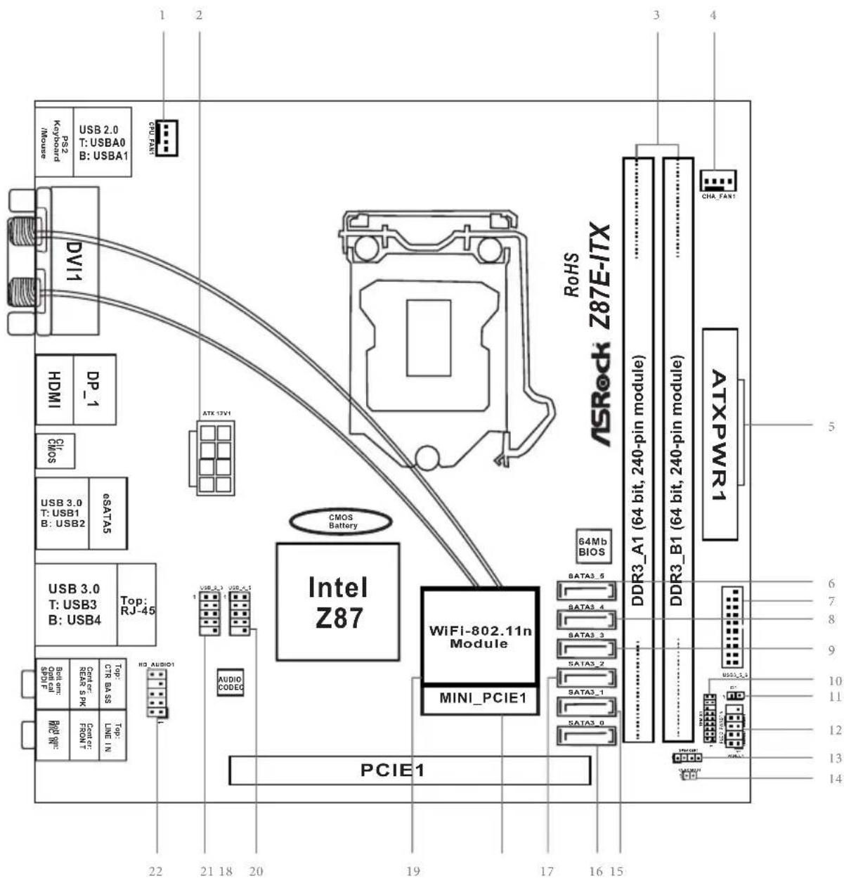
Motherboard Layout
No.Description
1 CPU Fan Connector (CPU_FAN1)
2ATX12VPower Connector (ATX12V1)
3 2 x 240-pin DDR3 DIMM Slots (DDR3_A1, DDR3_B1)
4 Chassis Fan Connector (CHA_FAN1)
5 ATX Power Connector (ATXPWR1)
6 SATA3 Connector (SATA3_5) (shared with eSATA)
7 USB 3.0 Header (USB3_5_6)
8 SATA3 Connector (SATA3_4) (shared with mSATA)
9 SATA3 Connector (SATA3_3)
10 TPM Header (TPMS1)
11 Chassis Intrusion Header (CI1)
12 System Panel Header (PANEL1)
13 Chassis Speaker Header (SPEAKER1)
14 Clear CMOS Jumper (CLRCMOS1)
15 SATA3 Connector (SATA3_1)
16 SATA3 Connector (SATA3_0)
17 SATA3 Connector (SATA3_2)
18 mini-PCI Express Slot (MINI_PCIE1)
19WiFi-802.11n Module
20 USB 2.0 Header (USB_4_5)
21 USB 2.0 Header (USB_2_3)
22 Front Panel Audio Header (HD AUDIO1)
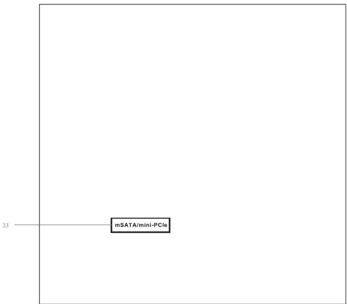
23 mSATA Connector (MINI_PCIE2)
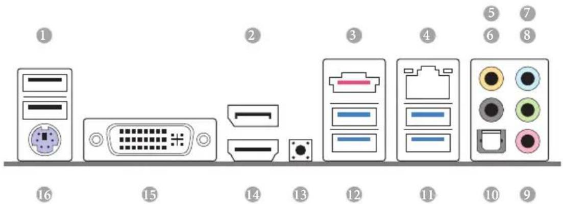
I/O Panel
No. Description No. Description
1 USB 2.0 Ports (USB01) 9 Microphone (Pink)
2 Display Port 10 Optical SPDIF Out Port
3 eSATA Connector***
11 USB 3.0 Ports (USB3_34)
4 LAN RJ-45 Port 12 USB 3.0 Ports (USB3_12)
5 Central / Bass (Orange) 13
Clear CMOS Switch
6 Rear Speaker (Black) 14 HDMI Port
7 Line In (Light Blue)
15 DVI-I Port
8 Front Speaker (Lime)**
16 PS/2 Keyboard/Mouse Port
- There are two LEDs on each LAN port. Please refer to the table below for the LAN port LED indications.
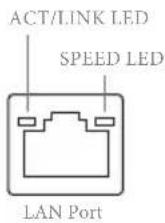
| Activity / Link LED Speed LED | |||
| Status Description Status Description | |||
| Off No Link Off | 10Mbps connection | ||
| Blinking | Data Activity | Orange | 100Mbps connection |
| On Link Green | Gbps connection | ||
**If you use a 2-channel speaker, please connect the speaker's plug into "Front Speaker Jack". See the table below for connection details in accordance with the type of speaker you use.
| Audio Output Channels | Front Speaker (No. 8) | Rear Speaker (No. 6) | Central / Bass (No. 5) | Line In (No. 7) |
| 2 V --- | ||||
| 4 V V --- | ||||
| 6 V V V --- | ||||
| 8 V V V V |

To enable Multi-Streaming, you need to connect a front panel audio cable to the front panel audio header. After restarting your computer, you will find the "Mixer" tool on your system. Please select "Mixer ToolBox", click "Enable playback multi-streaming", and click "ok". Choose "2CH", "4CH", "6CH", or "8CH" and then you are allowed to select "Realtek HDA Primary output" to use the Rear Speaker, Central/Bass, and Front Speaker, or select "Realtek HDA Audio 2nd output" to use the front panel audio.
*** The eSATA connector is shared with SATA3_5 connector.
Chapter 1 Introduction
Thank you for purchasing ASRock Z87E-ITX motherboard, a reliable motherboard produced under ASRock's consistently stringent quality control. It delivers excellent performance with robust design conforming to ASRock's commitment to quality and endurance.
In this manual, Chapter 1 and 2 contains the introduction of the motherboard and step-by-step installation guides. Chapter 3 contains the operation guide of the software and utilities. Chapter 4 contains the configuration guide of the BIOS setup.

Because the motherboard specifications and the BIOS software might be updated, the content of this documentation will be subject to change without notice. In case any modifications of this manual occur, the updated version will be available on ASRock's website without further notice. If you require technical support related to this motherboard, please visit our website for specific information about the model you are using. You may find the latest VGA cards and CPU support list on ASRock's website as well. ASRock website http:// www.asrock.com.
1.1 Package Contents
1.2 Specifications
Platform
quality Conductive Polymer Capacitors)
A-Style
Pentium® / Celeron® in LGA1150 Package
Turbo Boost 2.0 Technology
K-Series unlocked CPU
Chipset
Z87
Memory
1866(OC)/1600/1333/1066 non-ECC, un-buffered memory
(see CAUTION)
Extreme Memory Profile (XMP)1.3/1.2
Expansion
Slot
Graphics
be supported only with processors which are GPU integrated.
Sync Video with AVC, MVC (S3D) and MPEG-2 Full
HW Encode1, Intel* InTruTM 3D, Intel* Clear Video HD
Technology, Intel Insider™, Intel HD Graphics 4400/4600
2K (4096x2304) @ 24Hz
60Hz
60Hz
HBR (High Bit Rate Audio) with HDMI (Compliant HDMI monitor is required)
ports
with DVI-I, HDMI and DisplayPort ports
Audio
Audio Codec)
Ohms headsets)
LAN
Wireless
LAN
technology
Rear Panel
I/O
LED)
Speaker / Microphone
Storage
RAID 1, RAID 5, RAID 10, Intel Rapid Storage Technology 12 and Intel Smart Response Technology), NCQ, AHCI and "Hot Plug" (SATA3_5 connector is shared with the eSATA port; SATA3_4 connector is shared with the mSATA/mini-PCI Express slot)
functions
connector), supports NCQ, AHCI functions and Full-size mini-PCI Express modules
Connector
Connector)
BIOS
Feature
ment
Support
CD
Link MediaEspresso 6.5 Trial, Google Chrome Browser and
ToolBar, Start8, MeshCentral, Splashtop Streamer, Intel*
Hardware
Monitor
Adjust by CPU Temperature)
os
Certifica
tions
- For detailed product information, please visit our website: http://www.asrock.com

Please realize that there is a certain risk involved with overclocking, including adjusting the setting in the BIOS, applying Untied Overclocking Technology, or using third-party overclocking tools. Overclocking may affect your system's stability, or even cause damage to the components and devices of your system. It should be done at your own risk and expense. We are not responsible for possible damage caused by overclocking.

Due to limitation, the actual memory size may be less than 4GB for the reservation for system usage under Windows 32-bit operating systems. Windows 64-bit operating systems do not have such limitations. You can use ASRock XFast RAM to utilize the memory that Windows* cannot use.
1.3 Unique Features

ASRock A-Tuning
A-Tuning is ASRock's multi purpose software suite with a new interface, more new features and improved utilities, including XFast RAM, Dehumidifier, Good Night LED, FAN-Tastic Tuning, OC Tweaker and a whole lot more.

ASRock Instant Flash
ASRock Instant Flash is a BIOS flash utility embedded in Flash ROM. This convenient BIOS update tool allows you to update the system BIOS in a few clicks without preparing an additional floppy diskette or other complicated flash utility. Just save the new BIOS file to your USB storage and launch this tool by pressing <F6> or <F2> during POST to enter the BIOS setup menu to access ASRock Instant Flash. Please be noted that the USB flash drive or hard drive must use FAT32/16/12 file system.

ASRock APP Charger
Simply by installing the ASRock APP Charger makes your iPhone/iPad/iPod Touch charge up to 40% faster than before on your computer. ASRock APP Charger allows you to quickly charge many Apple devices simultaneously and even supports continuous charging when your PC enters into Standby mode (S1), Suspend to RAM (S3), hibernation mode (S4) or power off (S5).

ASRock XFast USB
ASRock XFast USB can boost the performance of your USB storage devices. The performance may depend on the properties of the device.

ASRock XFast LAN
ASRock XFast LAN provides faster internet access, which includes the benefits listed below. LAN Application Prioritization: You can configure your application's priority ideally and add new programs to the list. Lower Latency in Game: After setting online game's priority higher, it can lower the latency in games. Traffic Shaping: You can watch Youtube HD videos and download simultaneously. Real-Time Analysis of Your Data: With the status window, you can easily recognize which data streams you are currently transferring.

ASRock XFast RAM
ASRock XFast RAM is included in A-Tuning. It fully utilizes the memory space that cannot be used under Windows® 32-bit operating systems. ASRock XFast RAM shortens the loading time of previously visited websites, making web surfing faster than ever. And it also boosts the speed of Adobe Photoshop 5 times faster. Another advantage of ASRock XFast RAM is that it reduces the frequency of accessing your SSDs or HDDs in order to extend their lifespan.

ASRock Crashless BIOS
ASRock Crashless BIOS allows users to update their BIOS without fear of failing. If power loss occurs during the BIOS updating process, ASRock Crashless BIOS will automatically finish the BIOS update procedure after regaining power. Please note that BIOS files need to be placed in the root directory of your USB disk. Only USB 2.0 ports support this feature.

ASRock OMG (Online Management Guard)
Administrators are able to establish an internet curfew or restrict internet access at specified times via OMG. You may schedule the starting and ending hours of internet access granted to other users. In order to prevent users from bypassing OMG, guest accounts without permission to modify the system time are required.

ASRock Internet Flash
ASRock Internet Flash downloads and updates the latest UEFI firmware version from our servers for you without entering Windows OS. Please setup network configuration before using Internet Flash.

ASRock UEFI System Browser
ASRock System Browser shows the overview of your current PC and the devices connected.

ASRock Dehumidifier Function
Users may prevent motherboard damages due to dampness by enabling "Dehumidifier Function". When enabling Dehumidifier Function, the computer will power on automatically to dehumidify the system after entering S4/S5 state.

ASRock Easy RAID Installer
ASRock Easy RAID Installer can help you to copy the RAID driver from the support CD to your USB storage device. After copying the RAID driver to your USB storage device, please change "SATA Mode" to "RAID", then you can start installing the OS in RAID mode.
ASRock Easy Driver Installer
For users that don't have an optical disk drive to install the drivers from our support CD, Easy Driver Installer is a handy tool in the UEFI that installs the LAN driver to your system via an USB storage device, then downloads and installs the other required drivers automatically.

ASRock Interactive UEFI
ASRock Interactive UEFI is a blend of system configuration tools, cool sound effects and stunning visuals. The unprecedented UEFI provides a more attractive interface and more amusement.

ASRock Fast Boot
With ASRock's exclusive Fast Boot technology, it takes less than 1.5 seconds to logon to Windows 8 from a cold boot. No more waiting! The speedy boot will completely change your user experience and behavior.

ASRock Restart to UEFI
Windows® 8 brings the ultimate boot up experience. The lightning boot up speed makes it hard to access the UEFI setup. ASRock Restart to UEFI allows users to enter the UEFI automatically when turning on the PC. By enabling this function, the PC will enter the UEFI directly after you restart.

ASRock Good Night LED
ASRock Good Night LED technology offers you a better sleeping environment by extinguishing the unessential LEDs. By enabling Good Night LED in the BIOS, the Power/HDD LEDs will be switched off when the system is powered on. Good Night LED will automatically switch off the Power and Keyboard LEDs when the system enters into Standby/Hibernation mode as well.

ASRock USB Key
In a world where time is money, why waste precious time everyday typing usernames to log in to Windows? Why should we even bother memorizing those foot long passwords? Just plug in the USB Key and let your computer log in to windows automatically!

ASRock Home Cloud
This motherboard supports remote wake with the onboard Intel LAN, so you can connect with your PC from anywhere in the world. You will be able to power your PC on or turn it off, monitor and take control of it remotely with another smartphone, tablet or computer.
ASRock FAN-Tastic Tuning
ASRock FAN-Tastic Tuning is included in A-Tuning. Configure up to five different fan speeds using the graph. The fans will automatically shift to the next speed level when the assigned temperature is met.
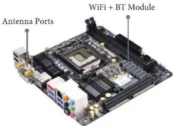
1.4 WiFi-802.11n Module and ASRock WiFi 2.4GHz Antenna
WiFi + BT Module
This motherboard comes with an exclusive WiFi 802.11 a/b/g/n/ac + BT v4.0 module that offers support for WiFi 802.11 a/b/g/n/ac connectivity standards and Bluetooth v4.0. WiFi + BT module is an easy-to-use wireless local area network (WLAN) adapter to support WiFi + BT. Bluetooth v4.0 standard features Smart Ready technology that adds a whole new class of functionality into the mobile devices including Apple's most recent iPhone 4S. BT 4.0 also includes Low Energy Technology and ensures extraordinary low power consumption for PCs. The 2T2R WiFi solution sets a WiFi high speed standard and offers max link rate up to 866Mbps.
- The transmission speed may vary according to the environment.
- The WiFi + BT module is supported under Windows* 8 / 8 64-bit / 7 / 7 64-bit only.
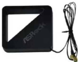
ASRockWiFi2.4GHz Antenna
Chapter 2 Installation
This is a Mini-ITX form factor motherboard. Before you install the motherboard, study the configuration of your chassis to ensure that the motherboard fits into it.
Pre-installation Precautions
Take note of the following precautions before you install motherboard components or change any motherboard settings.
Failure to do so may cause physical injuries to you and damages to motherboard components.
NEVER place your motherboard directly on a carpet. Also remember to use a grounded wrist strap or touch a safety grounded object before you handle the components.
in the bag that comes with the components.
tighten the screws! Doing so may damage the motherboard.
2.1 Installing the CPU

- Before you insert the 1150-Pin CPU into the socket, please check if the PnP cap is on the socket, if the CPU surface is unclean, or if there are any bent pins in the socket. Do not force to insert the CPU into the socket if above situation is found. Otherwise, the CPU will be seriously damaged.
- Unplug all power cables before installing the CPU.
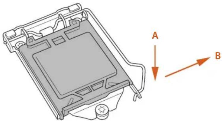
1
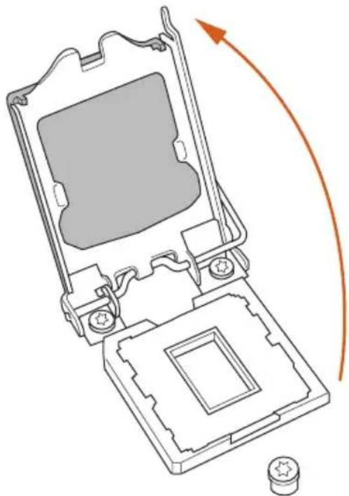
2
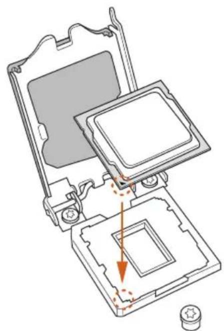
3
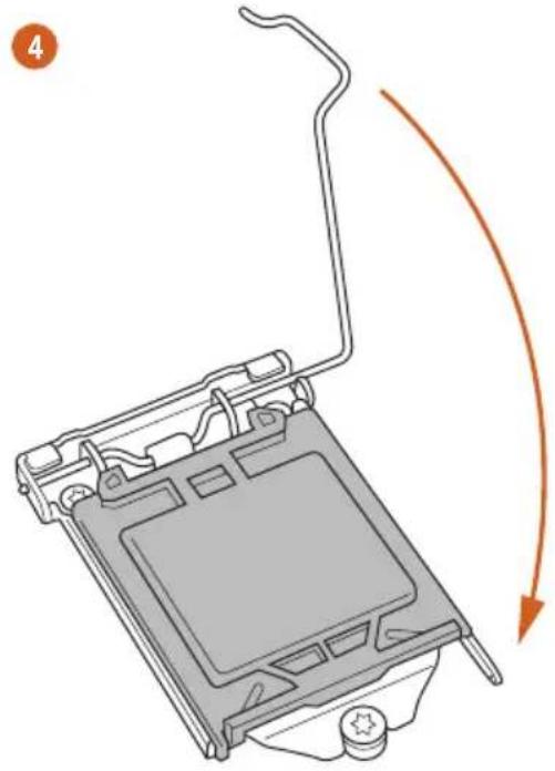
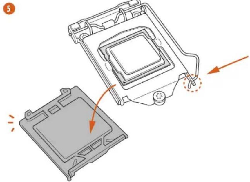

Please save and replace the cover if the processor is removed. The cover must be placed if you wish to return the motherboard for after service.
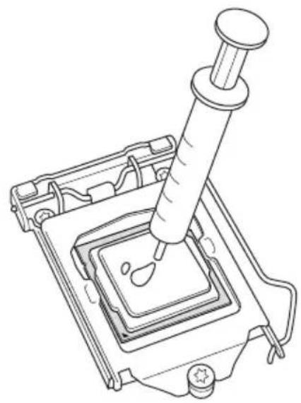
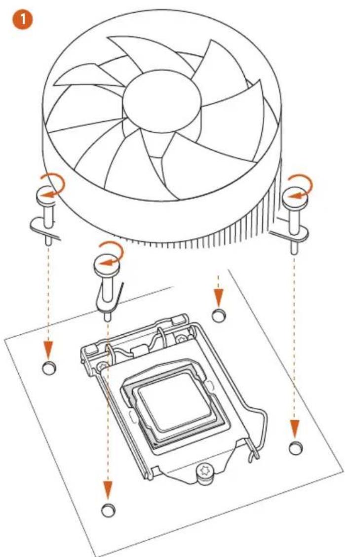
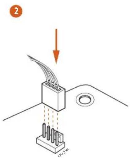
2.2 Installing the CPU Fan and Heatsink
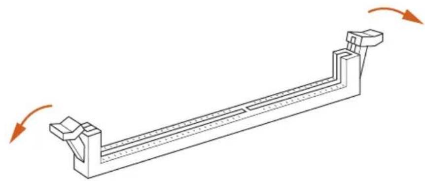
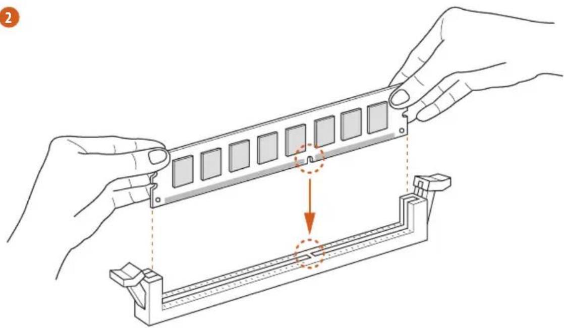
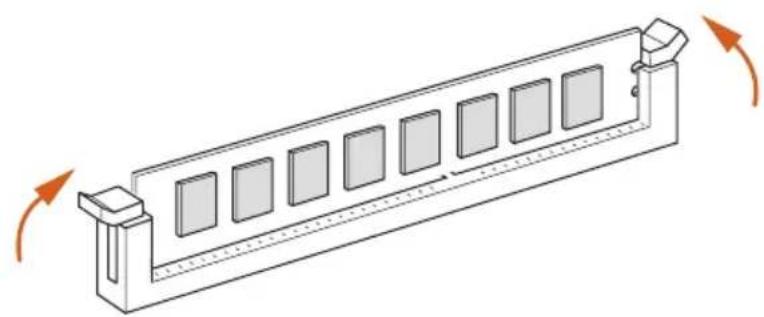
2.3 Installing Memory Modules (DIMM)
This motherboard provides two 240-pin DDR3 (Double Data Rate 3) DIMM slots, and supports Dual Channel Memory Technology.

- For dual channel configuration, you always need to install identical (the same brand, speed, size and chip-type) DDR3 DIMM pairs.
- It is unable to activate Dual Channel Memory Technology with only one memory module installed.
- It is not allowed to install a DDR or DDR2 memory module into a DDR3 slot; otherwise, this motherboard and DIMM may be damaged.

The DIMM only fits in one correct orientation. It will cause permanent damage to the motherboard and the DIMM if you force the DIMM into the slot at incorrect orientation.
1
2
3
2.4 Expansion Slots (PCI and PCI Express Slots)
There is 1 PCI Express slot, 1 mini-PCI Express slot, and 1 mSATA/mini-PCI Express slot on this motherboard.

Before installing an expansion card, please make sure that the power supply is switched off or the power cord is unplugged. Please read the documentation of the expansion card and make necessary hardware settings for the card before you start the installation.
PCIe slots:
PCIE1 (PCIe 3.0 x16 slot) is used for PCI Express x16 lane width graphics cards.
MINI_PCIE1 (mini-PCie slot) is used for WiFi module.
MINI_PCIE2 (mSATA/mini-PCIe slot) is used for mSATA or mini-PCIe module.
*** The mSATA/mini-PCIe slot is shared with SATA3_4 connector.
2.5 Jumpers Setup
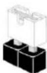
The illustration shows how jumpers are setup. When the jumper cap is placed on the pins, the jumper is "Short". If no jumper cap is placed on the pins, the jumper is "Open".
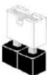
Short
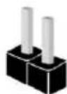
Open
Clear CMOS Jumper
(CLRCMOS1)
(see p.1, No. 14)

2-pin Jumper
Short: Clear CMOS
Open: Default
CLRCMOS1 allows you to clear the data in CMOS. The data in CMOS includes system setup information such as system password, date, time, and system setup parameters. To clear and reset the system parameters to default setup, please turn off the computer and unplug the power cord, then use a jumper cap to short the pins on CLRCMOS1 for 3 seconds. Please remember to remove the jumper cap after clearing the CMOS. If you need to clear the CMOS when you just finish updating the BIOS, you must boot up the system first, and then shut it down before you do the clear-CMOS action.

- The Clear CMOS Switch has the same function as the Clear CMOS jumper.
- If you clear the CMOS, the case open may be detected. Please adjust the BIOS option "Clear Status" to clear the record of previous chassis intrusion status.
2.6 Onboard Headers and Connectors

Onboard headers and connectors are NOT jumpers. Do NOT place jumper caps over these headers and connectors. Placing jumper caps over the headers and connectors will cause permanent damage to the motherboard.
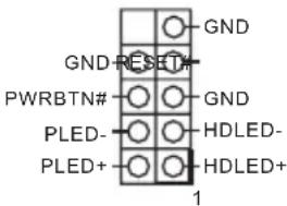
System Panel Header (9-pin PANEL1)
(see p.1, No. 12)
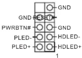
Connect the power switch, reset switch and system status indicator on the chassis to this header according to the pin assignments below. Note the positive and negative pins before connecting the cables.

PWRBTN (Power Switch):
Connect to the power switch on the chassis front panel. You may configure the way to turn off your system using the power switch.
RESET (Reset Switch):
Connect to the reset switch on the chassis front panel. Press the reset switch to restart the computer if the computer freezes and fails to perform a normal restart.
PLED (System Power LED):
Connect to the power status indicator on the chassis front panel. The LED is on when the system is operating. The LED keeps blinking when the system is in S1/S3 sleep state. The LED is off when the system is in S4 sleep state or powered off (S5).
HDLED (Hard Drive Activity LED):
Connect to the hard drive activity LED on the chassis front panel. The LED is on when the hard drive is reading or writing data.
The front panel design may differ by chassis. A front panel module mainly consists of power switch, reset switch, power LED, hard drive activity LED, speaker and etc. When connecting your chassis front panel module to this header, make sure the wire assignments and the pin assignments are matched correctly.
Serial ATA3 Connectors
(SATA3_0:
see p.1, No. 16)
(SATA3_1:
see p.1, No. 15)
(SATA3_2:
see p.1, No. 17)
(SATA3_3:
see p.1, No. 9)
(SATA3_4:
see p.1, No. 8)
(SATA3_5:
see p.1, No. 6)
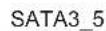


These six SATA3
connectors support SATA
data cables for internal
storage devices with up
to 6.0Gb / s data transfer
rate.SATA3_5 connector
is shared with the eSATA
port; SATA3_4 connector
is shared with the
mSATA/mini-PCIe slot.
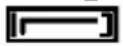
USB 2.0 Headers
(9-pin USB_2_3)
(see p.1, No. 21)
(9-pin USB_4_5)
(see p.1, No. 20)
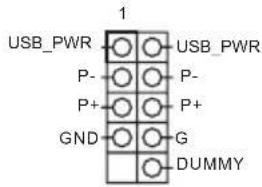
Besides two USB 2.0 ports
on the I/O panel, there
are two headers on this
motherboard. Each USB
2.0 header can support
two ports.
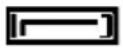
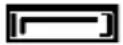
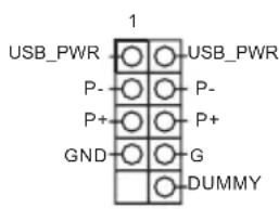
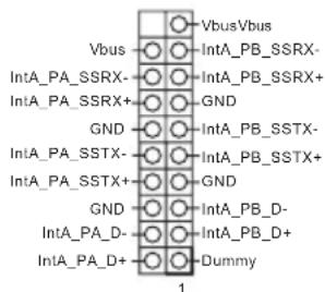
USB 3.0 Headers
(19-pin USB3_5_6)
(see p.1, No. 7)
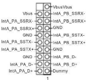
Besides four USB 3.0 ports
on the I/O panel, there
are one header on this
motherboard. Each USB
3.0 header can support
two ports.
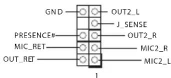
Front Panel Audio Header (9-pin HDAUDIO1)
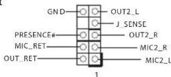
This header is for connecting audio devices to the front audio panel.

- High Definition Audio supports Jack Sensing, but the panel wire on the chassis must support HDA to function correctly. Please follow the instructions in our manual and chassis manual to install your system.
- If you use an AC'97 audio panel, please install it to the front panel audio header by the steps below:
A. Connect Mic_IN (MIC) to MIC2_L.
B. Connect Audio_R (RIN) to OUT2_R and Audio_L (LIN) to OUT2_L.
C. Connect Ground (GND) to Ground (GND).
D. MIC_RET and OUT_RET are for the HD audio panel only. You don't need to connect them for the AC'97 audio panel.
E. To activate the front mic, go to the "FrontMic" Tab in the Realtek Control panel and adjust "Recording Volume".
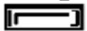
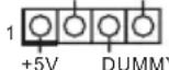
Chassis Speaker Header (4-pin SPEAKER1) (see p.1, No. 13)
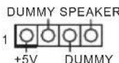
Please connect the chassis speaker to this header.
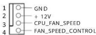
Chassis and Power Fan Connectors (4-pin CHA_FAN1) (see p.1, No. 4)
Please connect fan cables to the fan connectors and match the black wire to the ground pin.
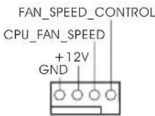
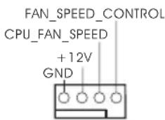
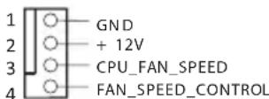
CPU Fan Connectors (4-pin CPU_FAN1) (see p.1, No. 1)
This motherboard provides a 4-Pin CPU fan (Quiet Fan) connector. If you plan to connect a 3-Pin CPU fan, please connect it to Pin 1-3.
| ATX Power Connector (24-pin ATXPWR1) (see p.1, No. 5) | This motherboard pro- vides a 24-pin ATX power connector. To use a 20-pin ATX power supply, please plug it along Pin 1 and Pin 13. | |
| ATX 12V Power Connector (8-pin ATX12V1) (see p.1, No. 2) | This motherboard pro- vides an 8-pin ATX 12V power connector. To use a 4-pin ATX power supply, please plug it along Pin 1 and Pin 5. | |
| Chassis Intrusion Header (2-pin CI1) (see p.1, No. 11) | This motherboard supports CASE OPEN detection feature that detects if the chassis cove has been removed. This feature requires a chassis with chassis intrusion detection design. | |
| TPM Header (17-pin TPMS1) (see p.1, No. 10) | This connector supports Trusted Platform Module (TPM) system, which can securely store keys, digital certificates, passwords, and data. A TPM system also helps enhance network security, protects digital identities, and ensures platform integrity. | |
1 Einleitung
IpepeMbIka c6poca
HaCTpoeK CMOS
(CLRCMOS1)
(Cm. cTp. 1, No 14)

2-KoHTaKTHaIepeMbYka
3aMKHyTa: C6poc Hactpoek CMOS a
Pa3OMKHyTa: IIO yMOJIyauHnIO
CLRCMOS1 nCIOB3yeTcI yIaJIeHnI aHHbIX CMOS. IaHHbIe CMOS BKIOUaOT B c6b TaKyo IHΦOpMaIIO O hAcTpoIke CnCTeMbI, KaK CNCTeMHbI IapOJIb, IaTa, BpeM I IapAMeTpBI HAcTpoIKn CnCTeMbI. YTo6bI c6pocNTb I 06HyJIITb NapaMeTpBI CnCTeMbI Ha HAcTpoIKN IO YMOnuHaIIIO, BbIKIOUHTe KOMIIbIOTep I IN3BJIeKITE BnIKy IN3 PO3eTKN, a 3aTeM KOJIpaYKOBoI IepemBuIKoI 3aMKHtE KOHTaKTBI HA CLRCMOS1 Ha 3 ceKynI. IocIe c6poca HAcTpoEK CMOS He 3a6yIbTe ChrTB KOJIpaYKOByIO IepemBuIKy. IIpr Heo6xoIMOCTN c6pocNTb HAcTpoIKN CMOS cpa3y IocIe o6HOJIeHnI BIOS chauJa Ipepe3aIpy3nte CnCTeMy, a 3aTeM BbIKIOUHTe KOMIIbIOTep IpeEi c6pocOM HacTpoEK CMOS.

- IIpehna3nauhenue nepeknoaemenia c6poca hacmpoek CMOS anaoeunho npedha3nauhenio nepembuku c6poca hacmpoek CMOS.
- C6poc hacmpoek CMOS mojem npubecmu K onpedehenu 8ckpbumno kopnyca. Ymoobu o6hynumb 3anucb npdebdyuezo onpedehenu 8ckpbumna Kopnyca, ucnonb3yume napamemp Clear Status (O6hynumb cocmohue) BIOS.
1.4 Kolodkn pa3bembl, pacnoIooKeHHbIe Ha MaTePnHcKoI nlaTe

PacnoiokeHHbe Ha MamepuHcko nIame KOIOOku u pa3bEmu nepbMukAMU HE HbIHomc. HE ycmanabuaime Ha 3mu KOIOOku u pa3bEmu KOIIauKObble nepbMtu. Ycmanobka KOIIauKOBbx nepbUeK Ha 3mu KOIOOku u pa3bEmu MoJem bbl6amb Heycmpanumoe nopeKdene MamepuHcko nnambl.
KoIOIka CnCTeMHoI
IIaHEnI
(9-KoHTaKTHa IA, PA NE
(CM. cTp. 1, No 12)
IoiKIOUHTe
paioIOKeHHbIe Ha
KOpIyCe BbIKIOuHaTeJIb
IIITaHnI, KHOIIKy
Ipe3aRpy3KN I
IHIMKaTOP COCTOHN H
CnCTeMbIK 3TOI KOIOJKe
B COOTBeTcTBnI C
pacPpeJeHHeM
KOHTaKTOB,
IIpNBdeEHbIM HnKe.
IpeE IOIKIOueHHeM
Ka6eJe OIPpeJeNTe
IOIOXHTeJIbHbI
IN OTPuaTeJIbHbI
KOHTaKTbI.

PWRBTN (Khonka numahan):
Iodknoeue klonku numanua, pacnooxenou na nepeoneu nanenu Kopnyca. MoKHO hacmpounb nopdoK bkiouehue cucmembl c ucnolb3obauem Klonku numanua.
RESET (Khonka nepe3a2py3ku):
Iopknouhenue knonku nep3a2py3ku cuminemb, pacnoonkennho na nepeoneu nanenu Kopnyca. Hkaumte knonky nep3a2py3ku, umo6b nepe3anycmumb konnbomep, ecnu OH 3abuc u hopmaalhbl 3anyck He603mokeH.
PLED (cbe mooduohb uhoekamop numanu cucmembl):
Iodknuehe undukamop ccmohua, pacnoiokeheno ha nepeho naheu Kopnyca. Cbemoduohn undukamop zopum, kozda cucmema paobamaem. Kozda cucmema haxodumc b pekume okuhanu S1/S3, cbemoduod muaem. Kozda cucmema haxodumc b pekume okuhanu S4 uuu bkykuoyeha (S5), cbemoduod he zopum.
HDLED (cemoduodhui udukamop paobmb mecmko2o ducka):
IIOKluue Hcemoduoohno undukamoppaobmkecmko0 ducka, pacnoonkenho na nepehne naneu Kopnyca. Ccemoduoohb undukamop oopum, kOda kecmku duck bblnoHnem chumbuahe uu 3anuc daHbix.
Ipeodnnaenb moem 6bum pa3noi ha pa3nbix kopnycax. B ochobom nepeodnnaenb bknoaem b cebk konky numanu, konky nepezay3ku, cbemoduohu undukamop numanu, cbemoouohbu undukamop paobmb jecemko0 ducka, duhamuk u m. d. Ipu nodknoeenu nepedneu naehu K 3moi koiodke npabunbo nokkaouame npooba Ka konmakmam.
Pa3BeMBI Serial ATA3
(SATA3_0:
cm. ctp.1, N 16)
(SATA3_1:
cm. ctp.1, N 15)
(SATA3_2:
cm. ctp.1, No 17)
(SATA3_3:
cm.ctp.1,N9)
(SATA3_4:
cm.ctp.1,N8)
(SATA3_5:
cm.ctp.1,N6)
SATA3_5

SATA3_4
SATA3_3
SATA3_2
SATA3_1
SATA3_0

3TNIeCTb
pa3beMOB SATA3
IpeHa3HaYeHbI IJIa
IOnKIIoueHnKa6eNei
SATA BHyTppeHHNX
3aIIOMnHaIOuIX
ycTpoIcTBIIJI IpeJaUH
JaHHbIX CO CKOPOCTbIO
I06,0Γ6/c.Pa3bEm
SATA3_5 nCIOJIb3yETc
COBmecTHO C IIOPTOM
eSATA; pa3BeM SATA3_4
IcIIob3yeTc8coBMeCTHO
cTHe3IOM mSATA/PCI
Mini.
KoIooNk USB 2.0.
(9-KOHTaKTHa,
USB_2_3)
(CM. ctp. 1, N° 21)
(9-KOHTaKTHaH,
USB_4_5)
(cm. ctp. 1, N° 20)
Kpome nByx npToB USB
2.0 Ha NaHeII BBOJa-
BbIBOJaHaMaTePnHcKoI
IIaTe TaKke eCtB IBe
KoIIOKn. KaJaa
KoIIOka USB 2.0 MoXeT
IIIOJIeKINBaTbIbA
nopta.
KoIooNk USB 3.0.
(19-KoHTaKTHaH,
USB3_5_6)
(CM. ctp. 1, N°7)
KpomeyetbipexIopTOB
USB3.0HaNaHeINBBOJa-
BbIBOaHaMaTePnHcKoI
IIaTe TaKKe ecTb OHa
KoIOnKa. KaXJaA
KoIOnKa USB 3.0 MoXeT
PoiIeKINBaTb IBa
HOPTa.
AynokoloKa IpeJeHnei
IaHei
(9-KoHTaKTHaH, HD_
AUDIO1)
TaKoIOka
IpeHa3HaueHa
IIaIOKIOUeHnA ayIOOyCtpoiCTB K
IpeHNey aynOnnAHeN.

- Ayuocumema bicokozo pa3peuenu naoodepkuabaem fynkuuo pacno3nabua pa3bema, no dne enpaunbu npabomtu neobxodmo, mobtu npobod nanenu Kopnyca noadepkuean nepedauy cu2hanoe HDA. Incmpykuuu no ycmanobke cucmemcu. 0 tmon pykoobcme u pykoobcme ha kopnyc.
- IIpu ucnolb3oanu uyduonanaenu AC'97 nodkioquume ee k ayduokonoode nepeonedu naenu, ka yka3ano daee:
A. Itoeknoume Mic_IN (MIC) κ MIC2_L.
B. Iodknouome Audio_R (RIN) κ OUT2_R, Audio_L (LIN) κ OUT2_L.
C.Поdkлουчeme npobod 3a3eMlenu(GND)к konhmaуну 3a3eMlenu(GND).
D. Konmakmby MIC_RET u OUT_RET ucnb3yomc monbko do ayduonanaenu blyco2o pa3peuenu. Ipu ucnb3obauu ayduonanenu AC'97 ux nodknoaemb He hykho.
E. Ym06bI akmuBupoBamnb nepedHm MukpofoH, nepidOme Ha 8klaodky FrontMic nanenu ynpaBneuRealtek u ompezynupyime napamemp Recording Volume (TpomKocmb 3anucu).
KoIOKa HnHaMnKa
KopIIyca
(4-KoHTaKTHa, SPEAKER1)
(CM. cTp. 1, N° 13)
DUMMY SPEAKER
IpeHa3HaueHa IJIa IIOKIIIOUeHnI INHaMnKa KOpNyca.
Pa3bEmbln
BEHTNJITOPOB KOpIyca N
6IOKa NITaHn
(4-KoHTaKTbI, CHA_FAN1)
(CM. cTp. 1, N° 4)
PiPeHa3HaueHbIJI
PiKIOUeHnKa6eJe
pa3BeMOB BeHTnIaTOPOB
IIIOKIOUeHn YepHO
IPOBOJa K 3a3EmJeHIO.
Pa3bembIBeHTHITOPOB II
(4-KoHTaKTbI, CPU_FAN1)
(CM. cTp. 1, N° 1)
Ta MaTePnHcKa
IIaTa Cha6KeHa
4-KoHTaKTbIM pa3bEMOM
IIaMaIOUIyMIAIeO
BeHTNIaTopa I1I.
EcIN Bb co6bpaTeCb
IOIKIOuHTb
3-KoHTaKTbI
BeHTNIaTOp IpoUeCCopa,
IOIKIOuAte erOK
KOHTaKTam 1-3.
até 6,0 Gb/s. O conector
PLED (Sistem Güci LED):
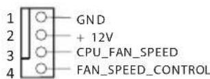
CPU Fan Baglayiclar1
(4-pinCPU_FAN1)
(bkz sf.1, No. 1)
1866(OC)/1600/1333/1066 ECC, B. 1
()
Extreme Memory Profile (XMP)1.3/1.2 signature
音长
二
其訛在對藥藥藥藥藥藥藥藥藥藥藥藥藥藥藥藥藥藥藥藥藥藥藥藥藥藥藥藥藥藥藥藥藥藥藥藥藥藥藥藥藥藥藥藥藥藥藥藥藥藥藥藥藥藥藥藥藥藥藥藥藥藥藥藥藥藥藥藥藥藥藥藥藥藥藥藥藥藥藥藥藥藥藥藥藥藥藻藻藻藻藻藻藻藻藻藻藻藻藻藻藻藻藻藻藻藻藻藻藻藻藻藻藻藻藻藻藻藻藻藻藻藻藻藻藻藻藻藻藻藻藻藻藻藻藻藻藻藻藻藻藻藻藻藻藻藻藻藻藻
Short

Open
Clear CMOS 结构
(CLRCMOS1)
(1,14反范

2.1.1.1
:Clear CMOS
:
- Extreme Memory Profile (XMP)1.3/1.2
扩充槽
图形
效和 VGA 输出。
用AVC、MVC(S3D)和MPEG-2 Full HW Encode1、Intel®
InTruTM3D、Intel*Clear Video HD技术、Intel*InsiderTM
Intel® HD Graphics 4400/4600
(4096x2304)
^® K-Series unlocked CPU
晶片組
Z87
記憶體
RESET (Switch Atur Ulang):
If you need to contact ASRock or want to know more about ASRock, you're welcome to visit ASRock's website at http://www.asrock.com; or you may contact your dealer for further information. For technical questions, please submit a support request form at http://www.asrock.com/support/tsd.asp
ASRock Incorporation
2F., No.37, Sec. 2, Jhongyang S. Rd., Beitou District,
Taipei City 112, Taiwan (R.O.C.)
ASRock EUROPE B.V.
Bijsterhuizen 3151
6604 LV Wijchen
The Netherlands
Phone: +31-24-345-44-33
Fax: +31-24-345-44-38
ASRock America, Inc.
13848 Magnolia Ave, Chino, CA91710
U.S.A.
Phone: +1-909-590-8308
Fax: +1-909-590-1026
For the following equipment:
Motherboard
(Product Name)
Z87E-ITX/ASRock
(Model Designation / Trade Name)
ASRock Incorporation
(Manufacturer Name)
2F., No.37, Sec. 2, Zhongyang S. Rd., Beitou District, Taipei City 112, Taiwan (R.O.C.)
(Manufacturer Address)
is herewith confirmed to comply with the requirements set out in the Council
Directive on the Approximation of the Laws of the Member States relating to
Electromagnetic Compatibility Directive (2004/108/EC) and Safety Directive (2006/95/ EC), the following standards are applied:
EN 55022:2006+A1:2007
EN 61000-3-2: 2009
EN 61000-3-3:2008
EN 55024:1998 + A1:2001 + A2:2003
IEC 61000-4-2: 2008;
IEC 61000-4-3:2010;IEC 61000-4-4:2010
IEC 61000-4-5:2005; IEC 61000-4-6:2008
IEC 61000-4-8:2009;IEC 61000-4-11:2004
EN60950-1:2005+A1:2009
IEC 60950-1:2006 + A11:2009 + A1:2010 + A12:2011
The following manufacturer / importer or authorized representative established within the EUT is responsible for this declaration:
ASRock EUROPE B.V.
(Company Name)
Bijsterhuizen 3151 6604 LV Wijchen The Netherlands
(Company Address)
Person responsible for making this declaration:

(Name, Surname)
A.V.P
(Position / Title)
Apr. 26, 2013
(Date)