
RM480E - Electric mower RYOBI - Free user manual and instructions
Find the device manual for free RM480E RYOBI in PDF.

| Product Type | Electric ride-on mower |
| Brand | RYOBI |
| Model | RM480E |
| Weight | 136.1 kg |
| Power Source | Rechargeable lead-acid battery |
| Cutting Width | 48 cm |
| Cutting Height | Adjustable from 25 to 100 mm (approx) |
| Recommended Tire Pressure | 1.6 bar |
| Charger | 220-240 V AC, 50/60 Hz, indoor use only |
| Initial Charge Time | 24 hours |
| Main Functions | Mowing, mulching, side discharge, cruise control, forward/reverse |
| Equipment | Adjustable seat, headlights, USB port, cup holder, media holder |
| Safety | Parking brake, operator presence locking system, side chute lock |
| Maintenance and Cleaning | Clean dry (compressed air or blower), do not use water |
| Spare Parts and Repairability | Use only original RYOBI parts; repairs by an authorized center |
| Warranty | 24 months (extension possible under conditions) |
| Intended Use | Domestic use, mowing lawn by trained adults |
| Maximum Slope | 15° |
| Guaranteed Sound Level | 100 dB(A) |
| Package Contents | Mower, seat, mulching cover, charger, tools, documents |
Frequently Asked Questions - RM480E RYOBI
User questions about RM480E RYOBI
0 question about this device. Answer the ones you know or ask your own.
Ask a new question about this device
Download the instructions for your Electric mower in PDF format for free! Find your manual RM480E - RYOBI and take your electronic device back in hand. On this page are published all the documents necessary for the use of your device. RM480E by RYOBI.
USER MANUAL RM480E RYOBI
natural_image
Black and white photo of a modern electric mobility scooter with visible wheels, steering wheel, and control panel (no text or symbols)
Important! It is essential that you read the instructions in this manual before assembling, maintaining and operating the product.
Safety, performance, and dependability have been given top priority in the design of your ride-on mower.
INTENDED USE
The ride-on mower is intended for outdoor use only.
The product is designed for domestic lawn mowing. The cutting blade should rotate approximately parallel to the ground over which it is being wheeled. All four wheels should touch the ground while mowing.
The product is to be used only in domestic application by adults who have received adequate training on the hazards and preventive measures or actions taken while using it.
Do not use the product for any other purpose.
GENERAL SAFETY WARNINGS
WARNING
Read all safety warnings, instructions, illustrations and specifications provided with this power tool. Failure to follow all instructions listed below may result in electric shock, fire, and/or serious injury.
Save all warnings and instruction for future reference.
The term “power tool” in the warnings refers to your mains-operated (corded) product or battery-operated (cordless) product.
WORK AREA SAFETY
- Keep work area clean and well lit. Cluttered or dark areas invite accidents.
- Do not operate power tools in explosive atmospheres, such as in the presence of flammable liquids, gases or dust. Power tools create sparks which may ignite the dust or fumes.
- Keep children and bystanders away while operating a power tool. Distractions can cause you to lose control.
ELECTRICAL SAFETY
■ Power tool plugs must match the outlet. Never modify the plug in any way. Do not use any adapter plugs with earthed (grounded) power tools. Unmodified
plugs and matching outlets will reduce risk of electric shock.
- Avoid body contact with earthed or grounded surfaces, such as pipes, radiators, ranges and refrigerators. There is an increased risk of electric shock if your body is earthed or grounded.
- Do not expose power tools to rain or wet conditions. Water entering a power tool will increase the risk of electric shock.
- Do not abuse the cord. Never use the cord for carrying, pulling or unplugging the power tool. Keep cord away from heat, oil, sharp edges or moving parts. Damaged or entangled cords increase the risk of electric shock.
■ When operating a power tool outdoors, use an extension cord suitable for outdoor use. Use of a cord suitable for outdoor use reduces the risk of electric shock.
■ If operating a power tool in a damp location is unavoidable, use a residual current device (RCD) protected supply. Use of an RCD reduces the risk of electric shock.
PERSONAL SAFETY
■ Stay alert, watch what you are doing and use common sense when operating a power tool. Do not use a power tool while you are tired or under the influence of drugs, alcohol or medication. A moment of inattention while operating power tools may result in serious personal injury.
■ Use personal protective equipment. Always wear eye protection. Protective equipment such as dust mask, non-skid safety shoes, hard hat or hearing protection used for appropriate conditions will reduce personal injuries.
■ Prevent unintentional starting. Ensure the switch is in the off-position before connecting to power source and/or battery pack, picking up or carrying the tool. Carrying power tools with your finger on the switch or energising power tools that have the switch on invites accidents.
■ Remove any adjusting key or wrench before turning the power tool on. A wrench or a key left attached to a rotating part of the power tool may result in personal injury.
- Do not overreach. Keep proper footing and balance at all times. This enables better control of the power in unexpected situations.
■ Dress properly. Do not wear loose clothing or jewellery. Keep your hair and clothing away from moving parts. Loose clothes, jewellery or long hair can be caught in moving parts.
If devices are provided for the connection of dust extraction and collection facilities, ensure these are connected and properly used. Use of dust collection can reduce dust-related hazards. - Do not let familiarity gained from frequent use of tools allow you to become complacent and ignore tool safety principles. A careless action can cause severe injury within a fraction of a second.
POWER TOOL USE AND CARE
- Do not force the power tool. Use the correct power tool for your application. The correct power tool will do the job better and safer at the rate for which it was designed.
- Do not use the power tool if the switch does not turn it on and off. Any power tool that cannot be controlled with the switch is dangerous and must be repaired.
■ Disconnect the plug from the power source and/or the battery pack, if detachable, from the power tool before making any adjustments, changing accessories or storing power tools. Such preventive safety measures reduce the risk of starting the power tool accidentally.
■ Store idle power tools out of the reach of children and do not allow persons unfamiliar with the power tool or these instructions to operate the power tool. Power tools are dangerous in the hands of untrained users. - Maintain power tools and accessories. Check for misalignment or binding of moving parts, breakage of parts and any other condition that may affect the power tool's operation. If damaged, have the power tool repaired before use. Many accidents are caused by poorly maintained power tools.
- Keep cutting tools sharp and clean. Properly maintained cutting tools with sharp cutting edges are less likely to bind and are easier to control.
■ Use the power tool, accessories and tool bits, etc. in accordance with these instructions, taking into account the working conditions and the work to be performed. Use of the power tool for operations different from those intended could result in a hazardous situation.
- Keep handles and grasping surfaces dry, clean, and free from oil and grease. Slippery handles and grasping surfaces do not allow for safe handling and control of the tool in unexpected situations.
BATTERY TOOL USE AND CARE
■ Recharge only with the charger specified by the manufacturer. A charger that is suitable for one type of battery pack may create a risk of fire when used with another battery pack.
■ Use power tools only with specifically designated battery packs. Use of any other battery packs may create a risk of injury and fire.
■ When battery pack is not in use, keep it away from other metal objects, like paper clips, coins, keys, nails, screws or other small metal objects, that can make a connection from one terminal to another. Shorting the battery terminals together may cause burns or a fire.
■ Under abusive conditions, liquid may be ejected from the battery; avoid contact. If contact accidentally occurs, flush with water. If liquid contacts eyes, additionally seek medical help. Liquid ejected from the battery may cause irritation or burns.
■ Do not use a battery pack or tool that is damaged or modified. Damaged or modified batteries may exhibit unpredictable behaviour resulting in fire, explosion or risk of injury.
- Do not expose a battery pack or tool to fire or excessive temperature. Exposure to fire or temperature above 130°C may cause explosion.
■ Follow all charging instructions and do not charge the battery pack or tool outside the temperature range specified in the instructions. Charging improperly
or at temperatures outside the specified range may damage the battery and increase the risk of fire.
SERVICE
■ Have your power tool serviced by a qualified repair person using only identical replacement parts. This will ensure that the safety of the power tool is maintained.
■ Never service damaged battery packs. Service of the battery packs should only be performed by the manufacturer or authorised service providers.
■ When using the product, the safety rules must be followed. For your own safety and that of bystanders, please read these instructions before operating the product. Please keep the instructions safe for later use.
- Allow only responsible adults, who are familiar with and understand the instructions, to use the product.
■ Be familiar with the controls and the correct use of the product.
■ Always use safety protective devices. Do not use the product without the side discharge chute in place and working properly. The mulch cover should be correctly installed and working properly during mulching operation.
■ Be aware of possible hazards when not using the product or when changing accessories. Following this rule will reduce the risk of electric shock, fire, or serious personal injury.
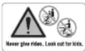
■ Never carry passengers or children, even when the blades have stopped. They may fall off and be seriously injured or interfere with the safe operation of the product. Children who have been given rides in the past may suddenly appear in the mowing area for another ride and be run over or backed over by the product.
- Keep in mind that the operator or user is responsible for accidents or hazards occurring to other people or their property.
■ Never allow children or people with reduced physical, sensory, or mental capabilities or
persons not familiar with these instructions to operate, clean, or maintain the product. Local regulations may restrict the age of the operator. Children should be adequately supervised to ensure they do not play with the product.
- Follow the manufacturer's instructions for proper operation and installation of accessories. Use only accessories approved by the manufacturer. The use of other accessories may increase the risk of injury.
■ Never interfere with the intended function of a safety device or reduce the protection provided by a safety device. Check the proper operation of the safety devices regularly.
■ Never tamper with safety devices. Check the proper operation of the safety devices regularly.
■ Never use the product while people, especially children, or pets are within 15 m because of the danger of objects being thrown by contact with the blade.
■ Do not use the product when there is a risk of lightning.
■ Do not operate the product in poor lighting. The operator requires a clear view of the work area to identify potential hazards. - Keep hands and feet away from the cutting area, which is located under the mower deck and inside the side discharge chute. Keep clear of the side discharge chute opening at all times. Do not reach under the mower deck.
■ Follow instructions for changing accessories.
PREPARATION
■ Wear heavy, long trousers, long sleeves, and sturdy anti-slip footwear. Do not wear short trousers, sandals, or go barefoot. Avoid wearing clothing that is loose fitting or that has hanging cords or ties.
■ Always wear safety glasses with side shields. Use a face mask if operation is dusty.
■ Objects struck by the blade can cause severe injuries to persons. Thoroughly inspect the area where the product is to be used, and remove all rocks, sticks, metal, wire, bones, toys, or other foreign objects.
Remember, string or wire may entangle with the blades.
■ Before use, always visually inspect the product to ensure that blades, blade nuts, and the cutter assembly are not worn or damaged.
■ Replace worn or damaged blades and nuts in sets to preserve balance.
■ Replace worn or damaged parts before operating the product.
■ Never direct discharged material toward anyone. Plan the mowing pattern to avoid discharge of material toward bystanders, roads, sidewalks, windows, and cars. Also, avoid discharging material against a wall or obstruction, which may cause the material to ricochet back toward the operator.
OPERATION
■ The product must be started with the user properly seated and behind the steering wheel. Never start the product if:
• not all four wheels are on the ground
- the side discharge chute is exposed and is not protected by the bagging kit or mulch cover
- hands and feet of all persons are not clear of the cutting enclosure
■ Disengage the blades when the product is not in use.
■ Never use the product in a closed area.
■ Stop the blade when crossing gravelly surfaces to avoid discharging gravel and rocks. Drive the product slowly and carefully to avoid loss of control.
■ Turn on the motor carefully according to instructions, and keep hands and feet away from blades. Do not put hands or feet near or under rotating parts.
■ Do not mow in reverse unless absolutely necessary. Always look down and behind before and while reversing.
■ Before and while reversing, look behind and down for small children, bystanders, and pets.
■ Use extra care when approaching blind corners, shrubs, trees, or other objects including overhanging shrubs, which may block your view.
■ Slow down before turning.
■ Slopes are a major factor related to loss of
control and tip-over accidents, which can result in severe injury or death. Operation on all slopes requires extra caution. If you cannot back up the slope or if you feel uneasy on it, do not mow it. Never use the product on steep slopes greater than 15°. Make a copy or cut out the "Slope Guide" at the back of this manual and use it to determine if your slope is too steep for safe operation.
- Never attempt to ride on a steep slope or mow a slope that is greater than 15^ .
- Mow up and down; not across the face of slopes.
- Avoid holes, ruts, bumps, rocks, property stakes, or other hidden objects. Uneven terrain could overturn the product. Tall grass can hide obstacles.
- Use a slow speed so you will not have to stop suddenly or accidentally accelerate while on a slope.
- Do not mow on wet grass when on a slope. Tyres may lose traction and you may lose control.
- Always keep the direction control switch in the forward position when going down slopes. Do not shift to neutral and coast downhill, which may cause you to lose control of the product.
- Avoid starting, stopping, or turning on a slope. If the tyres lose traction, disengage the blades and proceed slowly straight down the slope.
- Keep all movement on slopes slow and gradual. Do not make sudden changes in speed or direction, which could cause the product to roll over.
- Use extra care while using the product with attachments; they can affect the stability of the product. Do not use on steep slopes greater than 15^ .
- Do not try to stabilize the product by putting your foot on the ground.
- Do not use the product near drop-offs, ditches, excessively steep slopes, or embankments. The product could suddenly roll over if a wheel goes over the edge or if the edges caves in and result in death or serious personal injury.
■ Never leave a running product unattended. Always turn off the blades, engage the parking brake, stop the motor, and remove the start key before dismounting.
■ Watch for traffic when operating near roadways. Do not operate the mower on roadways.
ADDITIONAL CHARGER SAFETY WARNINGS
■The charger is for indoor use only.
■ Do not recharge primary cells (non-rechargeable).
■ Before every use, examine the supply cord for damage. If there are signs of damage, it must be replaced by a qualified person at an authorised service centre to avoid a hazard.
■ Charge the product indoors, in a well ventilated area. Do not charge the product in a confined space.
■ The charger is equipped with a plug featuring a grounding pin and must be plugged into a matching outlet that has been properly installed and grounded in accordance with all local codes and ordinances. Do not use adaptors or modify the plug provided. If it does not fit the outlet, have the proper outlet installed by a qualified electrician. The metal enclosure of the charger is not earthed.
ADDITIONAL BATTERY SAFETY WARNINGS
WARNING
To reduce the risk of fire, personal injury, and product damage due to short circuit, never immerse your tool, battery pack, or charger in fluid or allow a fluid to flow inside them. Corrosive or conductive fluids, such as seawater, certain industrial chemicals, and bleach or bleach-containing products, etc., can cause a short circuit.
WARNING
Risk of fi re, explosion, or burns. Do not disassemble, expose to heat above 60°C, or incinerate the battery pack.
■ The battery pack contains acid. If acid comes in contact with skin or clothing, flush immediately with water for 10 minutes. If liquid comes in contact with eyes, seek medical help immediately.
■ Do not charge battery packs that show signs of leaks. Dispose of them properly.
BATTERY PACK REMOVAL AND PREPARATION FOR RECYCLING
To preserve natural resources, recycle or dispose of batteries properly.
The product contains lead-acid batteries. Local regulations may prohibit disposal of lead-acid batteries in ordinary trash. Consult your local waste authority for information regarding available recycling and/or disposal options.
WARNING
Upon removal, cover the battery pack terminals with heavy-duty adhesive tape. Do not attempt to destroy or disassemble battery pack or remove any of its components. Lead-acid batteries must be recycled or disposed of properly. Never touch both terminals with metal objects and body parts as short circuit may result. Keep away from children. Failure to comply with these warnings could result in fire and/or serious injury.
TRANSPORTATION AND STORAGE
■Turn off the product, engage the parking brake, and remove the start key. Make sure that all moving parts have come to a complete stop. Allow the product to cool down before storing or transporting.
■ Clean all foreign materials from the product. Store the product in a cool, dry, and well-ventilated place that is inaccessible to children. The start key should also be removed and stored in a separate location out of the reach of children.
- Keep the product away from corrosive agents such as garden chemicals and de-icing salts. Do not store the product outdoors.
■ Use extra care when loading or unloading the product onto a trailer or truck. Step on the brake pedal as needed to control the speed. The product will freely roll if it is moved on an inclined surface without stepping on the brake pedal or engaging the parking brake. When loading or unloading the product, do not exceed the maximum recommended operation angle of 15^ .
WARNING
Use extreme caution when lifting or tilting the product for maintenance, cleaning, storage, or transportation. The blade is sharp. Keep all body parts away from the blade while it is exposed.
TRANSPORTING LEAD-ACID BATTERIES
Transport the battery in accordance with local and national provisions and regulations.
Follow all special requirements on packaging and labelling when transporting batteries by a third party. Ensure that no batteries can come in contact with other batteries or conductive materials while in transport by protecting exposed connectors with insulating, non-conductive caps or tape. Do not transport batteries that are cracked or leaking. Check with the forwarding company for further advice.
TOWING SAFETY WARNINGS
WARNING
Use extreme caution when towing the product. The blade is sharp. Keep all body parts away from the blade while it is exposed.
■ Use common sense when towing. Too heavy of a load while on a slope is dangerous. Tyres can lose traction with the ground and cause you to lose control of the product.
■ Follow the manufacturer's recommendations for wheel weights or counterweights.
■ Total towed weight must not exceed the maximum towing load of 226.8 kg (500 lbs.).
■ Attach tow equipment only at the hitch plate.
■ Never allow children or others on the towed equipment.
■ Stopping distance increases with speed and weight of load being towed. Travel slowly and allow extra time and distance to stop.
■ Do not turn sharply when towing. Use additional caution when turning or operating under adverse surface conditions. Use care when reversing.
MAINTENANCE
WARNING
Use only original manufacturer's replacement parts, accessories and attachments. Failure to do so can cause possible injury, can contribute to poor performance, and may void your warranty.
WARNING
Servicing requires extreme care and knowledge and should be performed only by a qualified service technician. Have the product serviced by an authorised service centre only. When servicing, use only original replacement parts.
■ Maintain the product with care and in good working condition. Keep blades sharp and guards in place and in working order. To prevent serious personal injury, prevent damage to the product, and to maintain best performance, replace damaged, bent, cracked, or unevenly worn out blades. An unbalanced blade causes vibration that could damage the motor drive unit or could cause personal injury.
■ Never make any adjustments or repairs while the motor is running and the blades are moving.
■ Remove the start key from the product before storing, servicing, or changing accessories. Such preventive safety measures reduce the risk of starting the product accidentally.
■ Turn off the product, engage the parking brake, and remove the start key. Make sure that all moving parts have come to a complete stop:
- before leaving the product unattended (including disposal of grass clippings).
- before clearing blockages or unclogging discharge chute
- before checking, cleaning, or working on the product
• before removing the mulch cover
- before opening the grass discharge chute cover
- after striking a foreign object - thoroughly inspect the product for any damage
– replace the blade if it is damaged in any way
– repair any damage before restarting and continuing to operate the product.
- whenever the product starts to vibrate abnormally (check immediately)
– inspect for damage, particularly the blades
– replace the blade if it is damaged in any way
– replace or repair any damaged parts
– check for and tighten any loose parts
■ You may make adjustments and repairs described in this manual. For other repairs, have the product serviced by an authorised service centre only.
■ Contact an authorised service centre to replace damaged or unreadable labels.
■ Service on the product and the charger must be performed by qualified repair personnel only. Service or maintenance performed by unqualified personnel could result in injury to the user or damage to the product.
- Check all nuts, bolts and screws at frequent intervals for proper tightness to ensure that the product is in safe working condition.
■ The blade bolts must be tightened to the recommended torque.
- Check the brakes before each use and frequently during use. Adjust and service as required.
■ The side discharge chute is a spring-loaded guard that covers the side discharge opening on the cutting deck and deflects grass clippings and debris away from the operator. Always ensure that the motor is off and the blades have stopped moving before inspecting, moving, cleaning, or performing maintenance on the side discharge chute.
■ Replace worn or damaged parts for safety.
- Replace damaged blades and bolts in sets to preserve balance.
■ Be careful during adjustment of the product to prevent entrapment of the fingers between moving blades and fixed parts of the product.
■ The cutting blades continue to rotate for a few seconds after the motor is shut off. When servicing the blades, be aware that
even though the power source is switched off, the blades can still be moved. Never place any part of the body in the blade area until you are sure the blades have stopped rotating.
■ The blade on the product is sharp. Use extreme caution and wear heavy-duty gloves when fitting, replacing, cleaning or checking bolt security.
■ After each use, clean the product with a soft, dry cloth. Any part that is damaged should be properly repaired or replaced by an authorised service centre.
- Keep the product free of grass, leaves, or other debris build up.
■ Do not use water to clean the product. Use an air moving device, such as a compressor or leaf blower to clean the product.
CLEARING BLOCKAGES
■Turn off the product, engage the parking brake, and remove the start key. Set the cutting deck to the maximum height. Make sure that all moving parts have come to a complete stop.
■ Always wear heavy-duty gloves when checking or clearing a blockage. The blades are sharp and the blockage itself could be a sharp object.
■ Check and carefully clear the side discharge chute for blockages.
■ If any blockages are found, remove carefully. Remember the blade may move during cleaning.
RESIDUAL RISKS
Even when the product is used as prescribed, it is still impossible to completely eliminate certain residual risk factors. The following hazards may arise during use, and the operator should pay special attention to avoid the following:
■ injury caused by vibration
– Always use the right tool for the job. Use designated handles and restrict working time and exposure.
- injury caused by exposure to noise
- Wear ear protection and limit exposure.
- injury from contact with the blades
- Keep unprotected body parts away from the blades at all times.
■ injury caused by thrown objects
– Wear full eye protection at all times.
RISK REDUCTION
It has been reported that vibrations from handheld tools may contribute to a condition called Raynaud's Syndrome. Symptoms may include tingling, numbness and blanching of the fingers, usually apparent upon exposure to cold. Hereditary factors, exposure to cold and dampness, diet, smoking and work practices are all thought to contribute to the development of these symptoms. There are measures that can be taken by the operator to possibly reduce the effects of vibration:
- Keep your body warm in cold weather. When operating the product, wear gloves to keep the hands and wrists warm. It is reported that cold weather is a major factor contributing to Raynaud's Syndrome.
■ After each period of operation, exercise to increase blood circulation.
■ Take frequent work breaks. Limit the amount of exposure per day.
If you experience any of the symptoms of this condition, immediately discontinue use and see your physician.
WARNING
Injuries may be caused, or aggravated, by prolonged use of a tool. When using any tool for prolonged periods, ensure you take regular breaks.
WHAT'S IN THE BOX
Ride-on mower x 1
- Seat assembly x 1
■ Tool kit and accessory box
- Open-ended spanners x 2
- Allen wrench x 1
- Torx wrench x 1
- Start keys x 2
- Mulch cover x 1
- Operator manual x 1
- Quick start guide x 1
- Assembly guide x 1
■ Steering column assembly box
- Charger x 1
NOTE: For a complete list of the steering column assembly, see the "Loose Parts List" section.
SYMBOLS ON THE PRODUCT


Safety alert.
Read and understand all instructions before operating the product. Follow all warnings and safety instructions.


Keep all bystanders, especially children and pets, at least 30 m away from the operating area.
Never carry children or anyone, even when the blades are off.

Always look down and behind you before and during backing and make sure children, bystanders, and pets are clear of the area.
Do not operate on inclines greater than 15^ . Mow up and down slopes, not across.
The guaranteed sound power level is 100 dB (A).

Keep hands and feet away from blade and cutting area. Do not step on the cutting deck or on the side discharge chute.


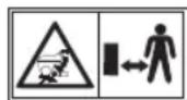
Keep all bystanders, especially children and pets, at least 30 m away from the operating area.

Beware of thrown or fl ying objects.
Never carry children or anyone, even when the blades are off.
Always look down and behind you before and during reversing, and make sure that children, bystanders, and pets are clear of the area.
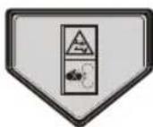
Keep hands and feet away from the blade and cutting area.

Brake
Step on the brake pedal to stop the product.

Parking brake


Accelerate
Step on the accelerator pedal to move forward or backward.
Charging port

Conforms to all regulatory standards in the country in the EU where the product is purchased

EurAsian Conformity Mark


The product can be operated in reverse with blades engaged when RMO button is pushed and red button light is on. Always look down and behind you before and when maneuvering in reverse. Mowing in reverse is not recommended.

Lift the blade engagement button up to engage. Press the blade engagement button down to disengage.

Cruise control allows the product to remain at a constant speed without the operator having to maintain pressure on the accelerator pedal. Refer to the "Setting the cruise control" section.
Waste electrical products should not be disposed of with household waste. Please recycle where facilities exist. Check with your local authority or retailer for recycling advice.

Ukrainian mark of conformity

For indoor use only

Time-lag fuse type

To reduce the risk of injury, user must read and understand user's manual before using this product.

Burst hazard

To reduce the risk of injury or damage, avoid contact with any hot surface.

Failure to use in dry conditions and to observe safe practices can result in electric shock.

Electric shock hazard.

Always unplug the charger from the power supply before connecting to or disconnecting from the battery.

Do not expose to rain or use in damp locations.

Do not expose to rain or use in damp condition.

Keep away from all sources of ignition, sparks, and flames. Do not cover any ventilation slots, and provide adequate ventilation during operation.

Keep out of the reach of children or untrained individuals.

Wear eye protection.

The battery pack contains acid. If acid comes in contact with skin or clothing, fl ush immediately with water for 10 minutes.

If liquid gets into your eyes, fl ush them with clean water for at least 10 minutes, then seek immediate medical attention

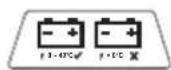
Non-spillable. Battery must be recycled.

The product contains lead-acid batteries. Local regulations may prohibit disposal of lead-acid batteries in ordinary trash. Consult your local waste authority for information regarding available recycling and/or disposal options.
Make sure that the side discharge chute is fully closed before operating the product.

Do not operate the product when the side discharge chute is open.

Driving the mower

Insert the start key, and turn the key to the ON position.

Set the direction control switch in the forward (F) position.

Step on the brake pedal to disengage the parking brake.

Pull up the blade engage knob to activate the blades.

Step on the accelerator pedal to mow the lawn.

Mowing in reverse

Step on the brake pedal, and bring the mower to a complete stop.

Push down the blade engage knob to turn off the blades.

Press the reverse mode button.
Pull up the blade engage knob to activate the blades.

Set the direction control switch in the reverse (R) position.

Step on the accelerator pedal, and reverse mow as needed.

Parking the mower

Stop the mower on a flat, level surface. Do not stop the product on slopes.
Step on the brake pedal, and engage the parking brake.

Set the direction control switch in the neutral (N) position.

Push down the blade engage knob to turn off the blades.

Turn the key to the OFF position.

Stopping the mower

Push down the blade engage knob to turn off the blades.

Step on the brake pedal.
Engage the parking brake.

Turn the key to the OFF position.

Remove the start key.
CAUTION
(Without Safety Alert Symbol) Indicates a situation that may result in property damage.
EN
FR
DE
DA
SV
FI
NO
SYMBOLS IN THIS MANUAL

Parts or accessories sold separately

Note

Warning
The following signal words and meanings are intended to explain the levels of risk associated with this product:
DANGER
Indicates an imminently hazardous situation, which, if not avoided, will result in death, or serious injury.
WARNING
Indicates a potentially hazardous situation, which, if not avoided, could result in death, or serious injury.
CAUTION
Indicates a potentially hazardous situation, which, if not avoided, may result in minor, or moderate injury.
ASSEMBLY
WARNING
To reduce the risk of injury, read and understand the assembly section of this manual before attempting to assemble the product. Save this guide for future reference.
ASSEMBLY SAFETY RULES
WARNING
Strictly adhere to all torque wrench tightening specifications. Failure to do so could cause serious personal injury.
All information, illustrations, photographs, and specifications contained in this manual are based on the latest product information available at the time of publication. Due to improvements or other changes, there may be some discrepancies in this manual. We reserve the right to make product changes at any time, without notice and without incurring any obligation to make the same or similar changes to any products previously built or sold.
■ Any person attempting to assemble the product must have proper training and experience. Read this manual carefully and follow all assembly procedures in this manual.
■ All assembly must be completed with the product on a level surface.
REQUIRED TOOLS
The following tools are needed for assembly:
■ Torque wrench
■ Tyre pressure gauge
- Socket wrench
- 12 mm socket
- 13 mm socket
- 6 mm hex bit
UNPACKING
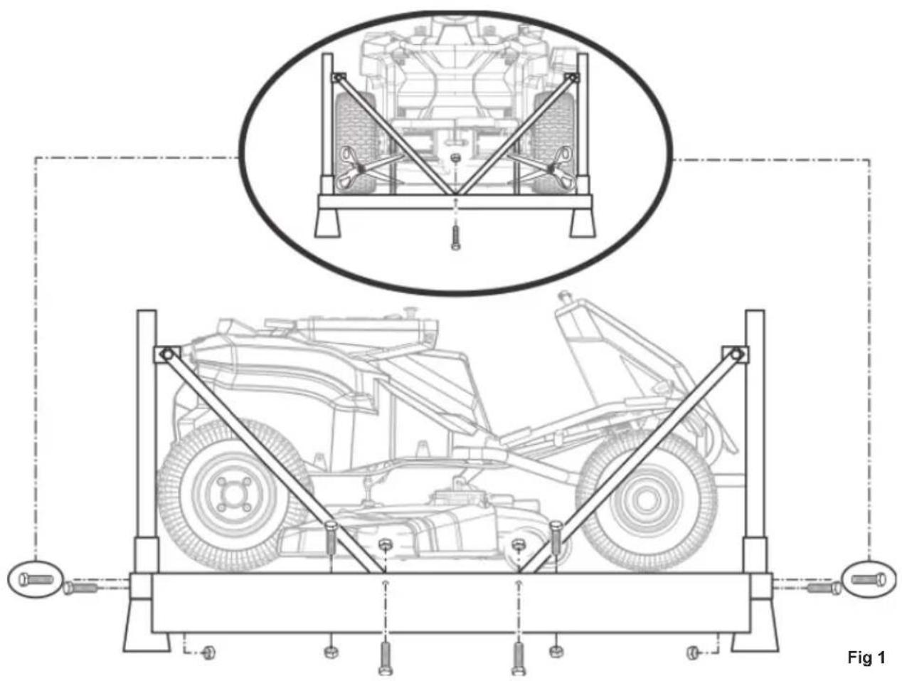
See fig. 1
■ Remove the bolts securing the corner and side braces to the frame bottom, then lift the braces to remove.
- Cut the nylon straps securing the front and rear wheel axles to the frame.
■ Remove the boxes containing loose parts, assembly hardware, and documentation.
■ Remove and set aside all accessible packaging and wrap from the unit and parts. Do not discard the packing material until you have carefully inspected and satisfactorily operated the product.
WARNING
If any parts on the "Loose parts list" section are already assembled to the product when you unpack it, verify that the part is assembled correctly, is properly tightened, and is torqued correctly (where applicable) before proceeding to the next assembly step. Use of a product that may have been improperly assembled could result in serious personal injury.
■ Inspect the product carefully to ensure that no breakage or damage occurred during shipping.
■ If any parts are damaged or missing, contact an authorised service centre.
NOTE: The product should be assembled while positioned on the frame bottom. Once assembly is complete, set the cutting deck to its maximum height, then position a ramp next to the frame bottom, and slowly and carefully drive the product off the frame.
WARNING
Use care when driving the product off of the frame, and step on the brake pedal as needed to control the speed. The product freely rolls if it is moved on an inclined surface without stepping on the brake pedal or engaging the parking brake. Failure to follow these instructions can result in loss of control and result in death, serious personal injury, or property damage.
WARNING
If no ramp is available, slowly and carefully drive the product off the frame in reverse while looking down and behind. Driving the product off the frame in the forward direction without a ramp can cause damage to the cutting deck.
EN
FR
DE
DA
SV
FI
NO
natural_image
Technical line drawing of a mechanical assembly with structural supports and a top-down view of a vehicle (no text or symbols present)LOOSE PARTS LIST
- Seat assembly x 1
-
Steering column assembly
Upper steering shaft x 1
Bolts x 2
Steering column x 1
Steering column cover x 1
Flange washers x 2
Spring x 1
Steering wheel hub x 1
Steering wheel x 1
Flat washer x 1
Flange nut x 1
Steering wheel cover x 1 -
Charger x 1
- Bumper x 1
- Start keys x 3
WARNING
If any parts are damaged or missing do not assemble the product until the parts are replaced with new original manufacturer's parts. Assembling the product with damaged, missing, or incorrect parts could result in serious personal injury.
natural_image
Line drawing of a medical or rehabilitation chair with open lid and seat (no text or symbols)
natural_image
Exploded view diagram of a washing machine showing key components like fan, drum, and sink (no text or labels)
natural_image
Illustration of an electronic device with a heat exchanger, coiled cable, and power plug (no text or symbols)
natural_image
Simple line drawing of a curved pipe or tube with two ends, enclosed in a dashed border (no text or symbols)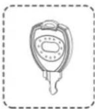
natural_image
Simple line drawing of a key with a handle and spout, enclosed in a dashed border (no text or symbols)WARNING
Strictly adhere to all torque wrench tightening specifications. Failure to do so could cause serious personal injury.
WARNING
Do not attempt to modify the product or create accessories not recommended for use with the product. Any such alteration or modification is a misuse and could result in a hazardous condition leading to possible serious personal injury.
WARNING
To prevent accidental starting that could cause serious personal injury, always remove the start key from the product when assembling the parts.
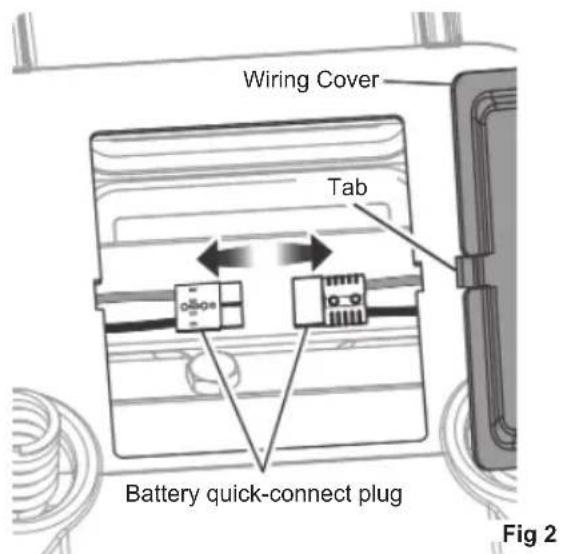
CONNECTING THE BATTERY
See fig. 2
When shipped from the factory, the product's batteries are disconnected.
To connect:
- Press the tabs on the wiring cover, and lift the cover to remove.
- Connect the two ends of the battery quick-connect plug together.
NOTE: Before reinstalling the wiring cover, install the seat as described in the next section.
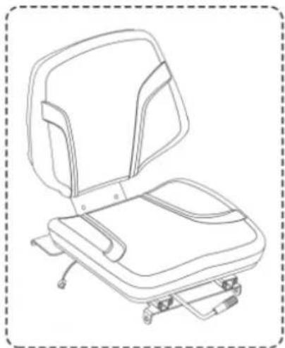
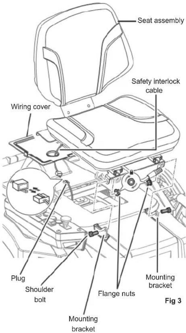
INSTALLING THE SEAT
See fig. 3
- Remove the bolts and flange nuts from seat mounting brackets.
- Place the seat assembly over the mounting brackets, aligning the holes as shown.
- Reinstall and securely tighten the bolts and flange nuts.
- Route the seat safety interlock cable through hole in the wiring cover, then connect to the plug on the mower.
- Reinstall wiring cover, and ensure that it is securely seated.
INSTALLING THE STEERING COLUMN
See fig. 4 - 5
- Install the upper steering shaft into the coupler, rotating as needed to align the hole in the shaft with bolt hole in the coupler.
- Install two bolts, and tighten securely to 20 Nm torque.
- Insert the steering column over the shaft. Note the tabs on the bottom of the steering column that fit into the holes in the opening and make sure that the steering column is securely seated.
- Install the steering column cover so that it is seated securely. The upper steering shaft protrudes through the opening in the cover.
- Install the flange washer (flange up), the spring, the second flange washer (flange down), and the steering wheel hub onto the upper steering shaft.
- Ensure the mower's wheels are pointed straight ahead, then install the steering wheel over the wheel hub.
- Install the flat washer and flange nut. Securely tighten the nut to 25 Nm torque.
- Install the steering wheel cover.
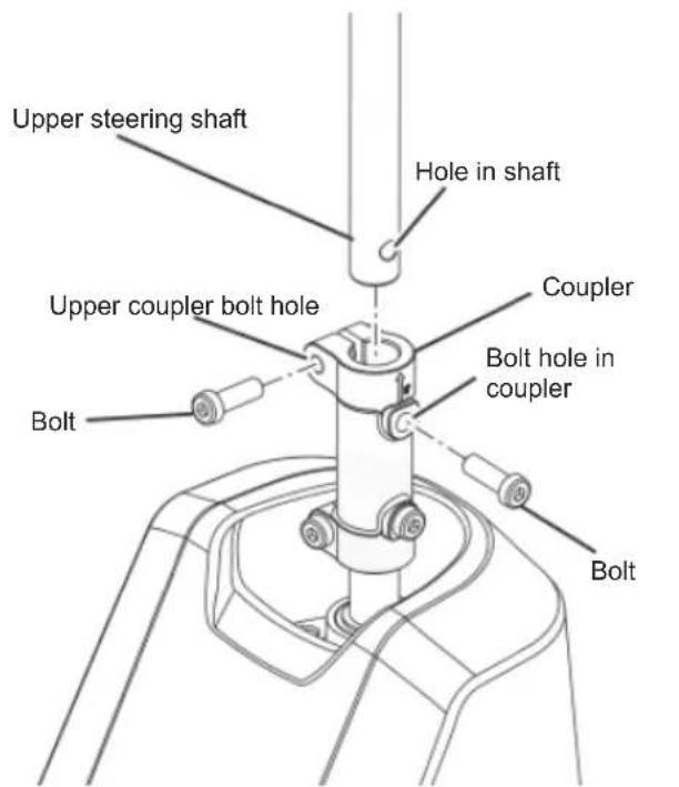
Fig 4
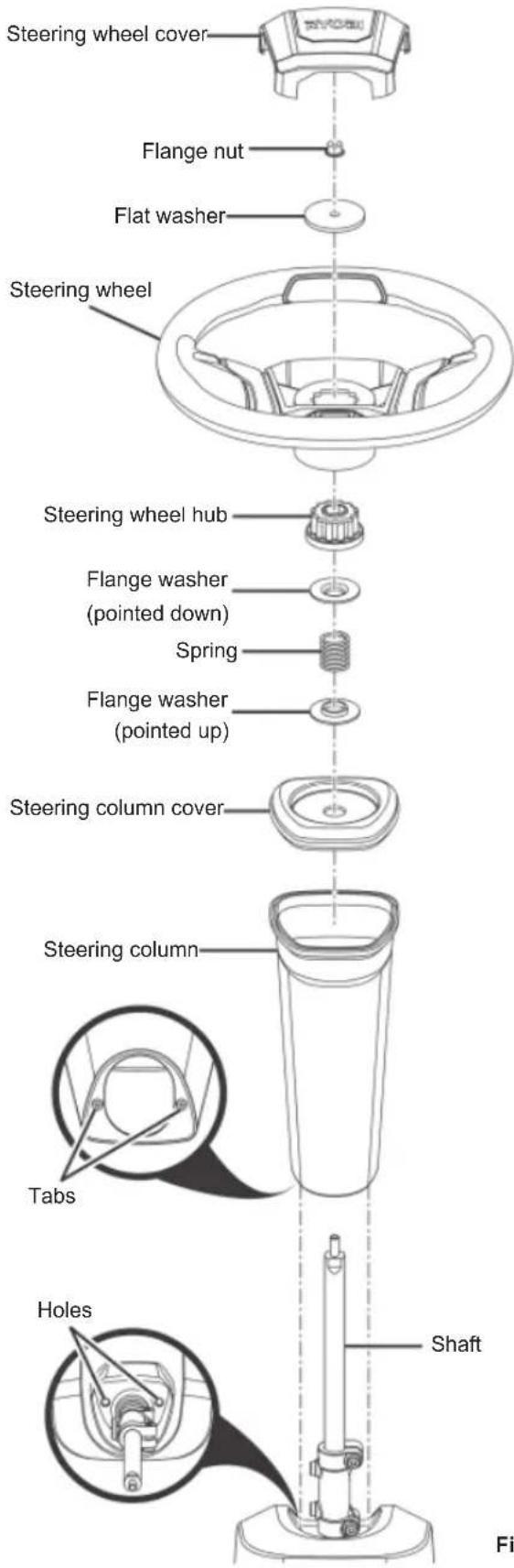
Fig 5
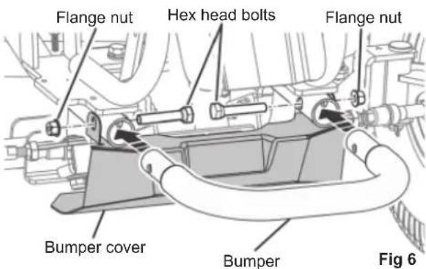
INSTALLING THE BUMPER
See fig. 6
- Remove the flange nuts and hex head bolts that secure the bumper cover to the mower frame.
- Install the bumper into the openings at the front of the mower frame as shown.
- Align the holes in the bumper, the mower frame, and the bumper cover. Reinstall and securely tighten the hex shoulder bolts and flange nuts.
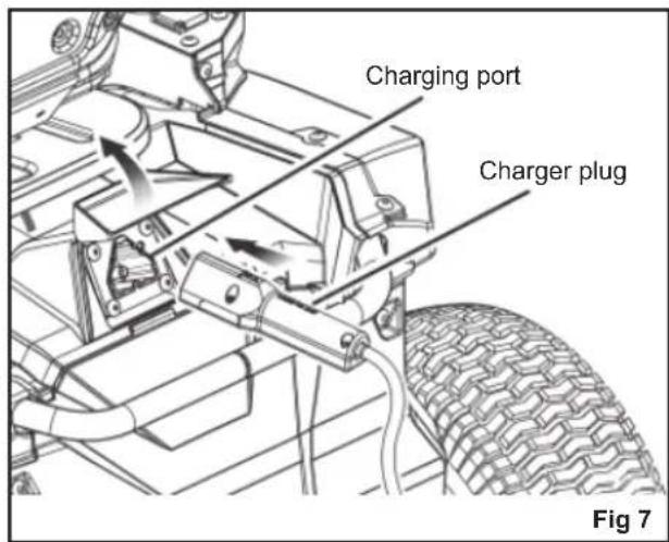
CHARGING THE PRODUCT
See fig. 7 - 8
Mower batteries must be charged for 24 hrs. before fi rst use. To verify that the mower batteries are fully charged, check the battery level indicator.
For best results:
■ Do not charge in an area of extreme heat or cold. The batteries charge best at temperatures from 0 °C to 40 °C.
■ Never charge a frozen battery.
■ Mount or place the charger in an area with adequate ventilation, without covering the cooling fins.
■ Make sure that both the charger and mower connections are clean and free of dirt or debris.
To charge:
- Insert the charger plug into the charging port on the mower, making sure that it is properly connected.
-
Connect the charger to a power supply using normal household current of of 220-240 VAC, 50 / 60 Hz. The batteries should automatically begin to charge.
-
When you are ready to mow, disconnect the charger from the power supply, then disconnect the charger from the mower.
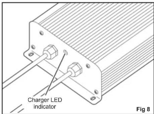
NOTE: The charger is equipped with a plug featuring a grounding pin and must be plugged into a matching outlet that has been properly installed and grounded in accordance with all local codes and ordinances. Do not use adaptors or modify the plug provided. If it does not fit the outlet, have the proper outlet installed by a qualified electrician. The metal enclosure of the charger is not earthed.
When powered, the LED indicator on the charger illuminates to indicate the charger's status. Refer to the following chart to determine the meaning of the LED's display.
WARNING
Always turn the power switch to the OFF position and remove the start key when charging the product and when the product is not in use.
WARNING
Leave the charger connected to mower when it is not in use. If it is not possible to leave the mower charger connected, make sure to fully charge the batteries at least once a month.
WARNING
Charge the product indoors, in a well-ventilated area. Do not charge the product in a confined space.
CHARGER LED INDICATOR
| Charger status | Connected to LED | Action | |||
| Power supply | Mower | Charger Mower | |||
| Standby Yes | No On Off | Ready to charge battery pack. | |||
| Charging Yes | Yes Yes On | Slow fl ashing | — | ||
| Charger error | Yes Yes | Off | Fast fl ashing | Battery temperature, battery capacity, or charger may be faulty. | |
| If the LED status shows error, wait for about 15 minutes to allow the battery and charger to cool down.If the LED status repeats a second time, reset the charger or reinsert the battery.If a different charger charges normally, the charger may be defective.If a different battery charges normally, battery capacity may be faulty. | |||||
| Fully charged | Yes Yes | On On | Fast charging is complete; charger maintains charge mode. | ||
| Interlock | No Yes | Off | Fast fl ashing | The plug is still connected to the mower. The mower cannot be started. | |
| Defective | Yes Yes | On | Fast fl ashing | Battery pack could be defective. | |
| If the LED status shows defective, reset the charger or reinsert the battery.If the LED status repeats a second time, try charging a different battery.If a different battery charges normally, dispose of the defective pack (see maintenance section). | |||||
FINAL CHECKS
CHECKING THE TYRE AIR PRESSURE
Check the air pressure in all tyres before use. Improper air pressure affects handling, steering response, traction, tyre life, level cutting, and operator comfort. Ensure that tyres are inflated to the recommended pressure (1.6 bar).
NOTE: Measured or adjust air pressure only when the tyres are cold.
WARNING
Check the tyre pressure carefully while inflating. Too much air in the tyre could cause the tyre to burst, causing serious personal injury.
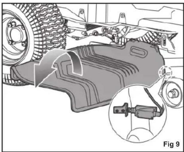
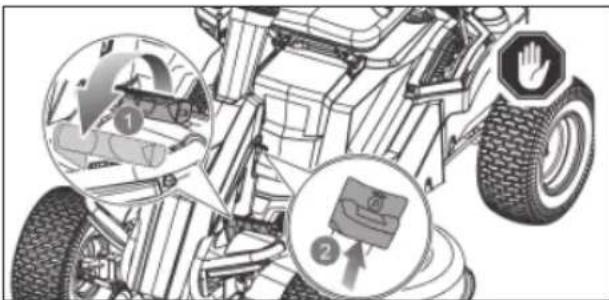
CHECKING THE SIDE DISCHARGE CHUTE SAFETY INTERLOCK SYSTEM
See fig. 9
Before using the product, check that the side discharge chute is properly closed. The side discharge chute has an interlock system that stops the blades if the side discharge chute is opened while the blades are running.
Stop using the product and have it serviced by an authorised service center if the blades do not stop when the side discharge chute is lifted during use by an obstacle.
natural_image
Mechanical assembly diagram showing a component being processed with a close-up inset (no text or symbols)The safety interlock system stops the blades if the operator leaves the mower while the blades are running. Test the system before each use to ensure that it is working correctly.
- Make sure that the direction control switch is in neutral (N) position, and the blade engage knob is down.
- Insert the start key, and turn the key to the ON position.
- Pull up the blade engage knob to activate the blades.
- Briefly stand up but do not get off the mower.
The blades should stop within 5 seconds. If the blades do not stop, contact an authorised service centre.
Do not operate the product until the safety interlock system has been repaired.
FEATURES
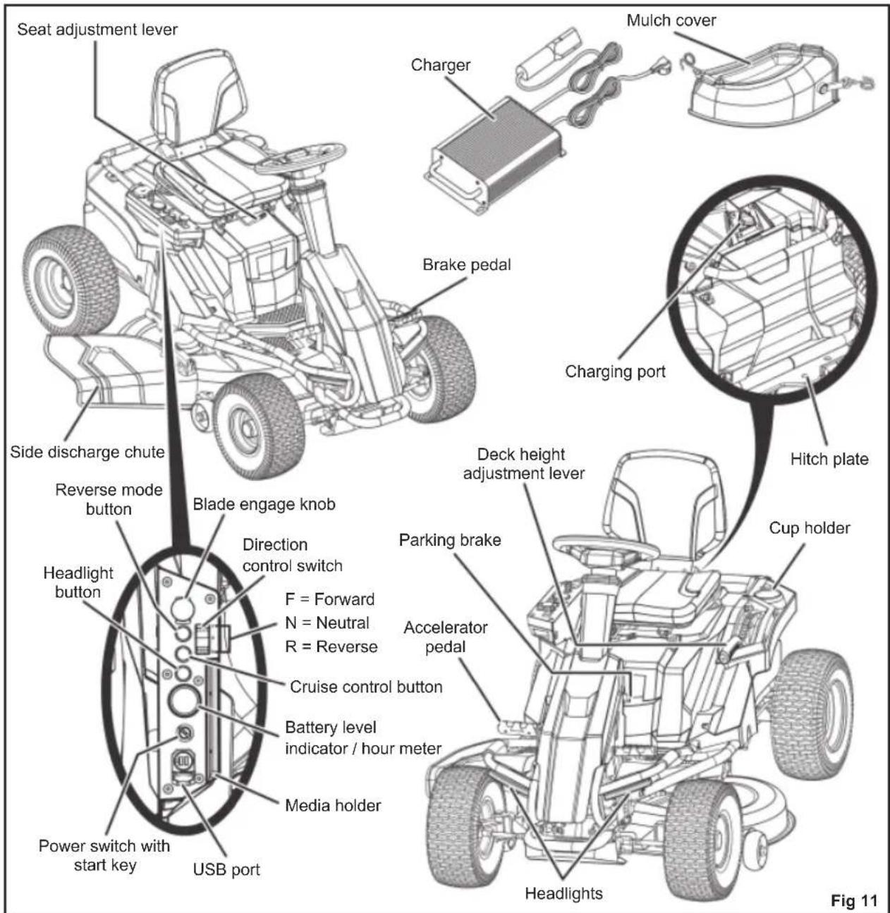
KNOW THE PRODUCT
See fig. 11
For safety, read and understand the information on the product and in this manual. Familiarise all operating features and safety rules before using the product.
ACCELERATOR PEDAL
The accelerator pedal controls the speed of the product.
BATTERY LEVEL INDICATOR / HOUR METER
The battery level indicator shows the amount of battery charge remaining. The hour meter tracks the total number of hours the product has been used (key in on position) for maintenance purposes.
BLADE ENGAGE KNOB
The blade engage knob activates or stops the cutting blades.
Pull up the blade engage knob to activate the cutting blades.
Push down the knob to stop the cutting blades. The blades should stop within 5 seconds. If the blades do not stop, contact an authorised service centre.
NOTE: For cutting in reverse, the reverse mode button must also be activated.
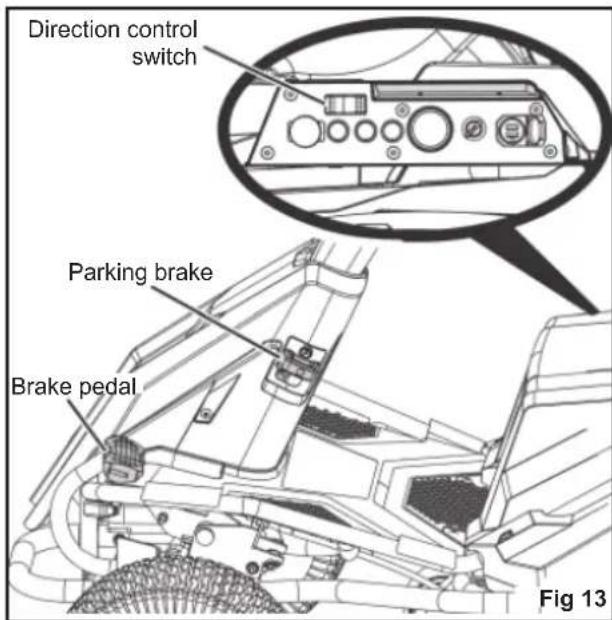
BRAKE PEDAL
The brake pedal slows down or stops the product.
CHARGER
The charger recharges the batteries of the mower. It has a key hole hanging feature for convenient, space-saving storage. When hanging by the keyhole slots, use at least one additional screw in the hole in the mounting fl ange to secure in place. Always mount in such a way that the charger's LED status light is visible while charging.
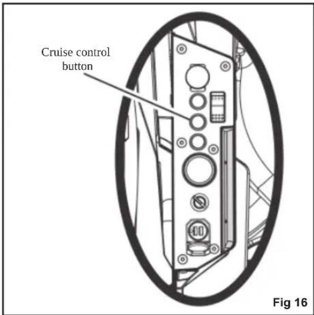
CRUISE CONTROL BUTTON
The cruise control button allows the product to continue forward at a set speed without needing to step on the accelerator pedal.
DECK HEIGHT ADJUSTMENT LEVER
The deck height adjustment lever raises or lowers the cutting deck.
DIRECTION CONTROL SWITCH
The direction control switch controls the direction movement of the mower. Available settings are forward (F), neutral (N), and reverse (R).
HEADLIGHT BUTTON
The headlight button turns ON and OFF the headlights.
MEDIA HOLDER
The media holders provide a convenient place to store your mobile phone or MP3 player when charging with the USB port.
MULCH COVER
The mulch cover covers the side discharge chute, which allows the mower blade to cut and recut for fi ner clippings.
PARKING BRAKE
The parking brake locks the product in the brake position.
POWER SWITCH WITH START KEY
The power switch turns ON and OFF the product. The start key must be inserted before the switch can be operated. When the key is in the accessory position, the power switch is also used to power optional manufacturer-approved mower accessories.
The operator presence safety interlock system stops the blades if the operator leaves the mower while the blades are running.
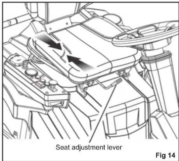
SEAT ADJUSTMENT LEVER
The seat adjustment lever moves the seat to the preferred position.
SIDE DISCHARGE CHUTE SAFETY INTERLOCK SYSTEM
The side discharge chute safety interlock system stops the blades if the side discharge chute is opened while the blades are running.
USB PORT
The USB charging port provides charging power of 5 V DC at up to 1 A for your cell phone, MP3 player, or other USB devices. Check the manual of your device for specific charging requirements.
Connect one end of a USB cable (not provided) to your device and the other end to the USB charging port on the product to charge your device.
NOTE: The USB port is powered only when the start key is in the ON position.
WARNING
Attempting to charge devices rated more than 1 A could damage the USB charging port and the mower. Always close the USB cover when not in use to prevent trapping debris in the port.
WARNING
Never use headphones or any electronic device, such as a smart phone or tablet, while operating the product. A lapse in concentration while operating the product may result in serious personal injury to the operator or a bystander.
HITCH PLATE
The hitch plate can be used to tow loads not more than 226.8 kg. (500 lbs.) in weight.
WARNING
Do not allow familiarity with products to make you careless. Remember that a careless fraction of a second is sufficient to inflict serious injury.
WARNING
Always wear eye protection with side shields. Failure to do so could result in objects being thrown into your eyes resulting in possible serious injury.
WARNING
Turn off the product, engage the parking brake, and remove the start key. Make sure that all moving parts have come to a complete stop before assembling parts, making adjustments, cleaning the product, or leaving the product unattended. This will prevent accidental starting that could cause serious personal injury.
WARNING
Always inspect the product for missing or damaged parts. Always check the blades for damage or uneven or excessive wear prior to use. Using the product with damaged or missing parts may result in serious personal injury.
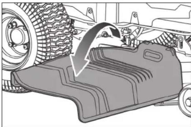
INSTALLING THE MULCH COVER
See fig. 12
The product is confi gured for side discharge when shipped. If mulching is preferred:
- Lift the side discharge chute.
- Place the mulch cover on the tab on the mower housing.
- Connect the mulch cover latches to the two side mounting points on the mower deck housing.
- Release the side discharge chute.
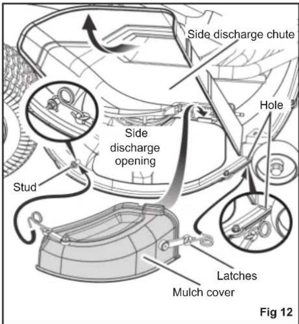
WARNING
Ensure that the side discharge chute fully closes when fi nished. Failure to do so may cause serious personal injury.
natural_image
Mechanical component diagram showing a curved arrow indicating motion or force direction (no text or symbols present)To engage the parking brake:
- Place the direction control switch in the neutral (N) position.
- Step on and hold the brake pedal.
- Lift the parking brake lever all the way up and hold.
- Release the brake pedal.
- Release the parking brake lever.
To disengage the parking brake:
■ Step on and release the brake pedal.
WARNING
Never leave the product unattended when the motor is running. Verify that the parking brake is engaged and the key has been removed. Failure to engage the parking brake could cause the product to move, and leaving the key could allow unauthorised use that could result in serious personal injury.
ADJUSTING THE SEAT
See fig. 14
Adjust the seat position to ensure that the user is able to make firm contact with the accelerator and brake pedals before operating the product.
To move the seat:
- Sit down on the seat, and lift the seat adjustment lever.
- While holding the lever, slide the seat to the preferred position.
- Release the lever, and make sure that the seat is locked in position before operating the product.
WARNING
Ensure that the seat is locked into place before operating the mower. A seat that is not secure can cause the operator to shift and lose control of the mower and result in possible death or serious personal injury.
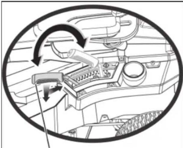
SETTING THE CUTTING DECK HEIGHT
See fig. 15
Before using the product, raise the deck height to the cutting position best suited for your lawn.
NOTE: To prevent scalping the lawn when encountering high spots, the cutting deck wheels should be positioned approximately 1.27 cm (1/2 in.) off the ground when the mower is at the desired cutting height. When shipped, the cutting deck wheels are set to the 3.81 cm (1.5 in.) position. Depending on your desired cutting height, you may need to change the position of the cutting deck wheels. To do so, refer to the "Adjusting Cutting Deck Wheels" section in this manual.
To adjust the cutting deck height:
- Stop the product and disengage the blades.
- Turn the start key to the OFF position and engage the parking brake.
- To raise the cutting deck, grasp the deck height adjustment lever, push left to disengage from slot, move toward the back of the mower, then push right into slot to secure.
- To lower the cutting deck, grasp the deck height adjustment lever, push left to disengage from slot, move toward the front of the mower, then push right into slot to secure.
WARNING
Hold the deck height adjustment lever firmly when setting the deck height and release only when it is secure in the desired slot. Quickly letting go of the lever may create a pinching or pulling hazard to the operator's hand.
natural_image
Diagram of a car dashboard with mechanical components and directional arrows indicating motion (no text or symbols)Deck height adjustment lever
Fig 15
SETTING THE CRUISE CONTROL
See fig. 16
Cruise control allows the product to remain at a constant speed without the operator having to maintain pressure on the accelerator pedal. It should only be used in the forward position on relatively smooth, straight surfaces, and should never be used on slopes or rough terrain.
To set the cruise control:
While driving the product forward, press the accelerator pedal until the desired rate of speed is achieved.
- Press the cruise control button. The light around the button illuminates to indicate that cruise control is active.
- Release pressure on the accelerator pedal. Mower speed should remain constant.
To release the cruise control:
- Tap on the accelerator pedal.
- Release the brake pedal, or press the cruise control button again. The light around the cruise control button goes out to indicate to that cruise control is no longer active.
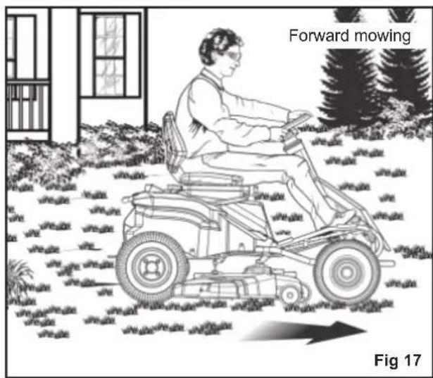
USING THE PRODUCT
See fig. 17 - 18
WARNING
Clear the area of bystanders before operating the product. If anyone enters the mowing area, stop immediately and do not return to mowing until the bystanders leave the area.
Before starting the product:
■ Ensure that the work area is clear of children, bystanders, and pets.
■ Clear the work area of objects that may be thrown by the mower blades.
■ Check the brake operation.
■ Check the tyre pressure.
■ Check for loose fasteners.
■ Make sure that all guards are in place and working properly.
■ Clean debris from mower.
■ Check the side discharge chute safety interlock system
■ Test the operator presence safety interlock system.
■ Adjust the seat to the preferred position.
■ Verify the battery charge level.
WARNING
When the level of battery charge reaches the red zone on the battery charge indicator, the blades automatically stop. Immediately return to the charging location, and recharge the mower. Continuing to mow when the battery charge level is in the red zone causes the mower to be stranded away from the charging area.
NOTE: If the mower is stranded away from the charger, set the direction control switch to the neutral (N) position, and push the mower back to the charging location.
WARNING
Use caution when crossing over gravelly paths or driveways. Before crossing, stop the blades and set the cutting deck to the maximum height to minimize the possibility of ricochet. Drive slowly to avoid loss of traction and control.
WARNING
Do not attempt to change the direction of operation while the mower is in motion. Always come to a complete stop before changing the mower direction.
Mowing:
- Set the cutting deck to the maximum height.
- Insert start key, and turn the key to the ON position.
- Disengage the parking brake.
- Set the direction control switch in forward (F) position, and drive to desired mowing location.
WARNING
Be certain that you have correctly set your intended direction of travel with the direction control switch before pressing the accelerator pedal. Failure to do so could result in you driving the mower in an unintended direction, which could cause loss of control or an accident resulting in death, serious personal injury, or property damage.
- Stop the mower, engage the parking brake, and turn the start key to the OFF position.
- Set the cutting deck to the preferred position.
- Turn the start key to the ON position, and disengage the parking brake.
- Pull up the blade engage knob to activate the blades, and step on the accelerator pedal to mow the lawn.
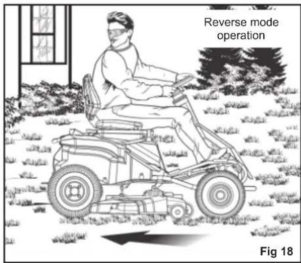
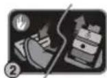
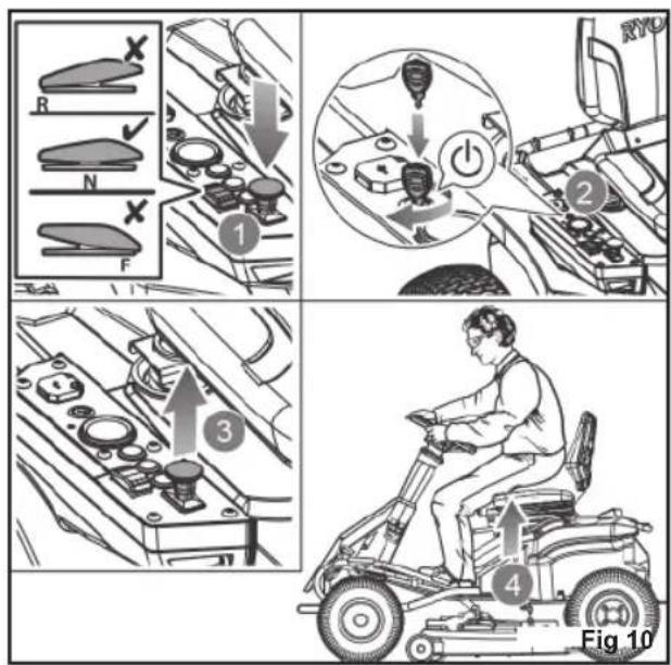
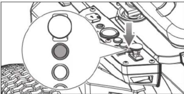
Reverse mode operation:
WARNING
The product will emit a constant beeping sound when operated in reverse with either the blade off or in reverse mode operation.
- Step on the brake pedal, and bring the product to a complete stop.
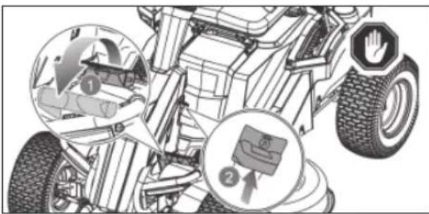
- Push down the blade engage knob to stop the blades.
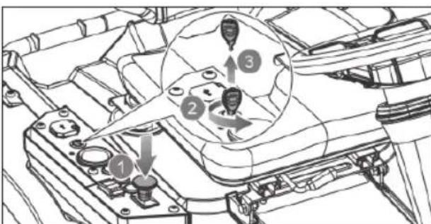
natural_image
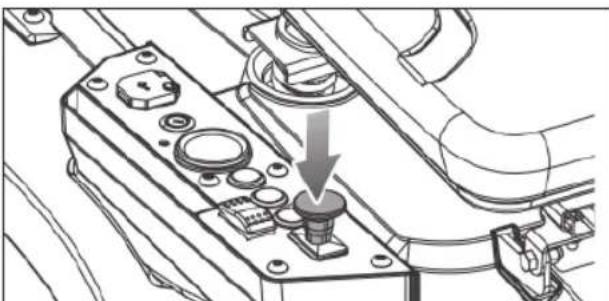
Technical line drawing of a mechanical component with a downward arrow indicating a specific part (no text or symbols present)- Press the reverse mode button.
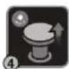
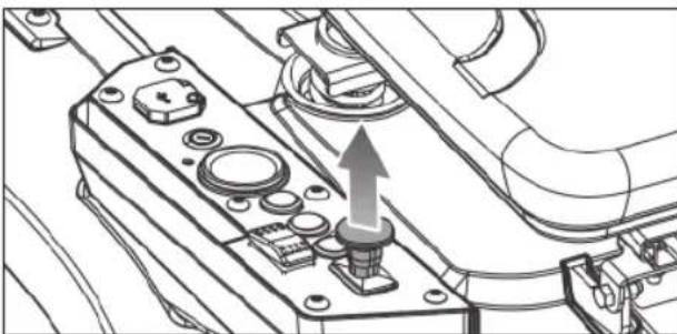
natural_image
Technical diagram of a mechanical assembly with a magnified inset showing circular components and a downward arrow (no text or symbols)- Pull up the blade engage knob.
natural_image
Technical line drawing of a mechanical assembly with no visible text or symbols- Set the direction control switch in reverse (R) position. Slowly step on the accelerator pedal, and reverse mow as needed.

WARNING
Do not mow in reverse unless absolutely necessary. Always look down and behind before and while reversing to make sure no children, bystanders, or pets enter the mowing area. Be aware that the reverse mode operation is activated when the reverse mode button is illuminated in red and a constant beeping sound is emitted. Remember that a careless fraction of a second is sufficient to inflict death or serious injury.
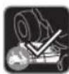
When mowing is complete:
WARNING
Stop the product on a flat, level surface. Do not stop the product on a slope.
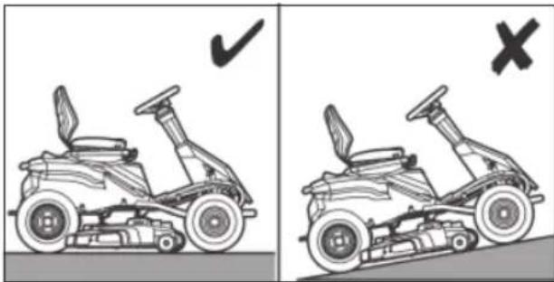
natural_image
Side-by-side comparison of two motor stoves showing steering wheel and suspension components, with checkmark and cross symbols indicating correct and incorrect states (no text or labels)- Step on the brake pedal, and engage the parking brake.
- Set the direction control switch in the neutral (N) position.
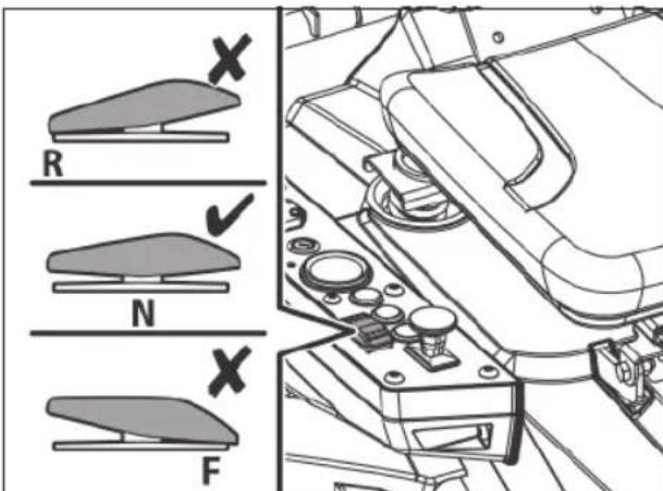
- Push down the blade engage knob to stop the blades. Turn the start key to the OFF position, and remove the key.
WARNING
If the product emits a beeping noise after you leave the seat, verify that the parking brake is engaged and the key has been removed. Failure to engage the parking brake could cause the product to move, and leaving the key could allow unauthorised use that could result in serious personal injury.
NOTE: Reverse mode operation resets each time the power switch is turned to the OFF position.
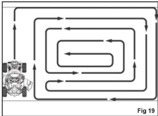
MOWING TIPS
See fig. 19
- Keep the mower blades sharp.
■ Make sure that the lawn is clear of stones sticks, wires, toys, tree nuts, tree branches, and other objects that could damage the mower blades or motor. Do not mow over property stakes or other metal posts. Such objects could damage the blade or be accidentally thrown by the product in any direction and cause serious personal injury to the operator and others.
■ For a healthy lawn, always cut off one-third or less of the total length of the grass.
flowchart
graph TD
    A["Vehicle"] --> B{Loop 1}
    B --> C{Loop 2}
    C --> D{Loop 3}
    D --> E{Loop 4}
    E --> F{Loop 5}
    F --> G{Loop 6}
    G --> H{Loop 7}
    H --> I{Loop 8}
    I --> J{Loop 9}
    J --> K["Loop 10"]
    K --> L["Loop 11"]
    L --> M["Loop 12"]
    M --> N["Loop 13"]
    N --> O["Loop 14"]
    O --> P["Loop 15"]
    P --> Q["Loop 16"]
    Q --> R["Loop 17"]
    R --> S["Loop 18"]
    S --> T["Loop 19"]
■ When mowing large areas, start by turning to the right so that clippings discharge away from shrubs, fences, and driveways. After one or two rounds, mow in the opposite direction, making left hand turns until finished.
■ Mow so that discharged clippings exit in the direction of the lawn area that has already been cut.
■ When cutting heavy grass, reduce speed for more effective cutting and a proper discharge of the clippings.
■ Do not cut wet grass. Wet grass sticks to the underside of the deck and prevent proper mulching of grass clippings.
■ New or thick grass may require a narrower cut or a higher cutting height.
- Keep the mower deck and side discharge chute clean. Remove grass clippings, leaves, dirt, and any other accumulated debris before and after each use. Do not spray the product with a garden hose to clean.
NOTE: Always stop product, allow blades to completely stop, and remove the start key before cleaning underneath the product.
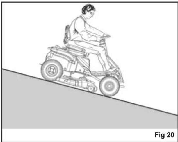
SLOPE OPERATION
See fig. 20
WARNING
Slopes are a major factor related to loss of control and tip-over accidents, which can result in severe injury or death. Operation on all slopes requires extra caution. If you cannot back up the slope or if you feel uneasy on it, do not mow it. Never use the product on steep slopes greater than 15°. Make a copy or cut out the "Slope Guide" at the back of this manual and use it to determine if your slope is too steep for safe operation.
■ Mow up and down; not across the face of slopes.
■ Do not mow on wet grass. Wet grass can cause the tyres to lose traction or slip on slopes, even though the brakes are functioning properly.
■ Watch out for holes, ruts, rocks, hidden objects, or bumps which can cause you to slip or trip. Tall grass can hide obstacles. Remove all objects such as rocks and tree limbs, which could be tripped over or thrown by the blade.
■ Do not mow near drop-offs, ditches, or embankments.
■ Drive slowly, and do not make sudden changes in speed or direction.
■ Avoid stopping on slope if at all possible. If stopping is unavoidable, make sure to engage the parking brake. When restarting, use lowest possible speed. If turning is necessary, exercise extreme caution when changing direction and always turn downhill.
■ Never attempt to stabilize the mower on a slope by placing your foot on the ground during operation.
■ Always use the brakes when travelling down the slope. Do not attempt to let the mower coast downhill in neutral.
If at any point the tyres lose traction while operating on a slope, disengage the blades and proceed slowly and carefully straight down the slope.
natural_image
Line drawing of a person riding an electric scooter on a slope, labeled 'Fig 20' (no text or symbols on the diagram itself)TRANSPORTING THE PRODUCT
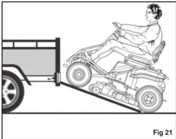
See fig. 21
WARNING
Use care when driving the product off of or onto a trailer or truck. Step on the brake pedal as needed to control the speed. The mower freely rolls if it is moved on an inclined surface without stepping on the brake pedal or engaging the parking brake. Failure to follow these instructions can result in loss of control and result in death, serious personal injury, or property damage.
WARNING
Use care when loading or unloading the product onto a trailer. Ensure that the cutting deck is raised to the highest position so that it is not caught on the ramp. The wheels on the product can go off the ramp or trailer, causing the product to pivot or tip over, and result in a crush hazard that can cause death or serious personal injury.
- Park the product on a level surface.
- Set the cutting deck to the maximum height.
- Position and secure a ramp to the trailer according to manufacturer's instructions.
NOTE: Use one full width loading ramp that is at least 30.5 cm. wider than the mower to minimise the risk of the wheels going off the side of the ramp.
-
Slowly drive the product onto the ramp and into the trailer.
-
Set the cutting deck to the lowest height.
-
Turn off the product, engage the parking brake, and remove the start key.
- Secure the product as needed using straps or cables to prevent movement during transport.
WARNING
To avoid accidental starting or movement of the product that could result in serious personal injury, always remove the start key and engage the parking brake when transporting the product.
natural_image
Line drawing of a person riding a car on an inclined ramp next to a vehicle (no text or symbols)MAINTAINING THE PRODUCT
WARNING
Turn off the product, engage the parking brake, and remove the start key. Make sure that all moving parts have come to a complete stop before performing any maintenance tasks to avoid accidental starting and possible serious personal injury.
WARNING
Always wear eye protection with side shields. Failure to do so could result in objects being thrown into your eyes resulting in possible serious injury.
WARNING
Consequences of improper maintenance may cause the product or safety features to not function correctly, thus increasing the potential for serious injury. Keep the product professionally maintained and safe.
WARNING
When servicing, use only original replacement parts. Use of any other parts can create a hazard or cause product damage.
WARNING
Strictly adhere to all torque wrench tightening specifications. Failure to do so could cause serious personal injury.
WARNING
Before each use, inspect the entire product for damaged, missing, or loose parts such as screws, nuts, bolts, and caps. Tighten securely all fasteners and caps and do not operate this product until all missing or damaged parts are replaced. Please contact an authorised service centre.
General maintenance
Avoid using solvents when cleaning plastic parts. Most plastics are susceptible to damage from various types of commercial solvents and may be damaged by their use. Use clean cloths to remove dirt, dust, oil, and grease.
WARNING
Do not at any time let brake fluids, gasoline, petroleum-based products, and penetrating oils, come in contact with plastic parts. Chemicals can damage, weaken, or destroy plastic, which can result in serious personal injury.
Remove any build-up of grass and leaves on or around the motor cover. Wipe the mower clean with a dry cloth occasionally. Do not use water.
ADJUSTING CUTTING DECK WHEELS
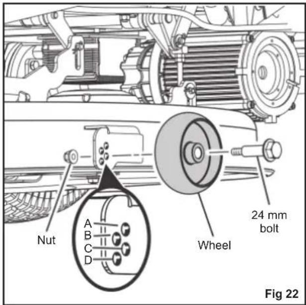
See fig. 22
The cutting deck wheels should be positioned approximately 1.27 cm. (1/2 in.) off the ground when the mower is at the desired cutting height. This will minimize the chance of scalping the lawn in most situations. When shipped, the wheels are positioned in Position A.
To adjust the cutting deck wheels:
- Park the product on a level surface and engage the parking brake.
- Turn off the product, and remove the start key. Make sure that all moving parts have come to a complete stop.
- Set the cutting deck to the preferred height setting.
-
Remove the nut and bolt securing the cutting deck wheel in place.
-
Move the wheel to the preferred position. Available hole positions are:
• 3.81 cm. (1.5 in.) (A)
- 4.44 ~cm (1.75 in.) (B)
- 5.08 cm. (2 in.) (C)
- 5.72 cm (2.25 in.) (D)
-
Replace the bolt and nut, and tighten securely. Torque nut to 5.42-8.13 Nm (4-6 ft. lbs.).
-
Repeat the steps with the remaining cutting deck wheel, making sure that both wheels are installed in the same position.
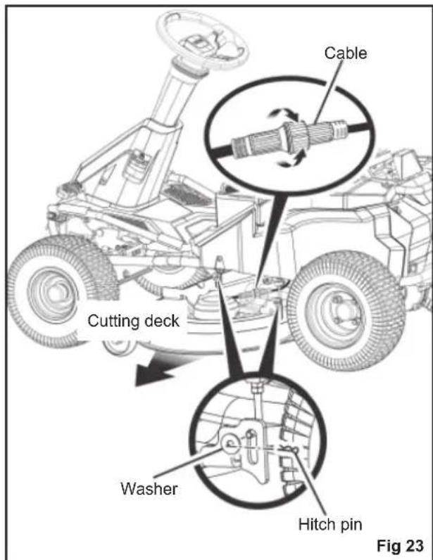
REMOVING THE CUTTING DECK
See fig. 23
The cutting deck can be removed from the mower to make accessing the blades easier when changing.
- Make sure that the direction control switch is in neutral (N) position, and blade engage knob is down.
- Turn off the product, engage the parking brake, and remove the start key. Make sure that all moving parts have come to a complete stop.
- Disconnect the cables that connect the cutting deck to the mower.
- Set the cutting deck to the lowest height.
- Remove the 4 hitch pins and washers that secure the cutting deck in place.
- Slide the deck out from under the mower. Reverse the steps to reinstall the cutting deck to the mower.
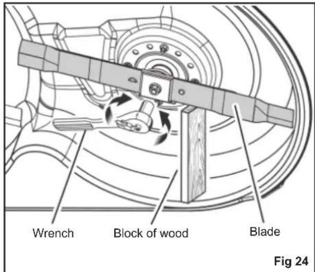
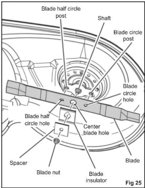
REPLACING THE CUTTING BLADES
See fig. 24 - 26
WARNING
Use only original replacement blades and blade bolts authorised by the manufacturer of your ride-on mower. Use of blades and blade bolts that are not authorised is hazardous and may damage your ride-on mower.
- Make sure that the direction control switch is in neutral (N) position, and blade engage knob is down.
- Turn off the product, engage the parking brake, and remove the start key.
- Set the cutting deck to the maximum height to allow access to the blades.
NOTE: If necessary, raise the mower by placing on a lift or using a jack and jack stands, or remove the cutting deck as described in the previous section to gain access to the blades.
WARNING
If raising the mower to access the blades, make sure that the mower is properly secured and the parking brake is engaged before proceeding. Failure to properly secure the mower could cause it to fall, resulting in death or possible serious personal injury.
- Wedge a block of wood between the blade and mower deck to prevent the blade from turning.
- Loosen the blade nut by turning it counterclockwise (as viewed from bottom of mower) using a 15 mm wrench or socket (not provided).
- Remove the blade nut, spacer, blade insulator, and blade.
- Place the new blade on the shaft against the corresponding blade posts. Ensure that blade is properly seated with the shaft going through centre blade hole and the two blade posts inserted into their respective holes on the blade. Make sure
that the blade is installed with the curved ends pointing up toward the mower deck and not down toward the ground. When seated properly, the blade should be flat against the blade posts.
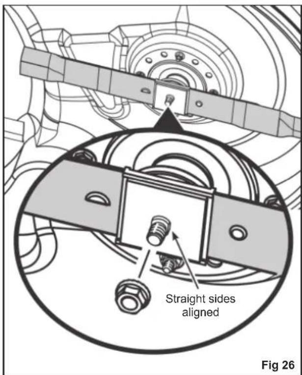
- Reinstall the blade insulator and spacer, making sure that the flat sides on each piece align and the straight sides of the opening on the spacer are aligned with the straight sides of the blade shaft.
NOTE: Make sure that all the parts are replaced in the exact order in which they were removed. - Thread the blade nut on the shaft and finger tighten.
- Torque the blade nut down clockwise using a torque wrench (not provided) to ensure the bolt is properly tightened. The recommended torque for the blade nut is 68 - 74 Nm (600-650 in. lbs.)
WARNING
Ensure that the blade is properly seated and the blade nut is tightened to the torque specifications above. Failure to properly attach the blade could cause it to come loose and result in possible serious personal injury.
Repeat the steps with the second blade, if needed.
TYRE MAINTENANCE
The product is equipped with tubeless tyres with the following dimensions:
■ Front tyres: 38.1x15.2x15.2 cm
■ Rear tyres: 40.6x16.5x20.3 cm
Tyre air pressure
Check the air pressure in all tyres before use. Improper air pressure will affect handling, steering response, traction, tyre life, level cutting, and operator comfort. Be sure tyres are inflated to the recommended pressure (1.6 bar).
NOTE: Tyre pressure should only be measured or adjusted when tyres are cold.
WARNING
Check the tyre pressure carefully while inflating. Too much air in the tyre could cause the tyre to burst, causing serious personal injury.
WARNING
Maintaining correct air pressure in the tyres is very important. Too little pressure could allow the tyre to rotate off the wheel rim. Too much pressure could cause the tyre to burst. Failure to maintain correct air pressure in the tyres could cause problems with mower operation and stability, causing serious personal injury.
TYRE REPAIR
If a leak or fl at tyre occurs due to a puncture, the tyre may be repaired using a plug-type patch. If the damage is from a cut, or if the puncture cannot be repaired using a plug, replace the tyre.
REPLACING TYRES
When tyres are worn, the traction of the mower decreases, which increases the chance of having an accident. Replace the tyres when the depth on the tread is 4 mm or less, or any time there is damage to the tyre. Always use original replacement tyres. Using improper tyres on the product could cause loss of control, which could cause serious personal injury.
Have the tyres replaced only by an authorised service centre.
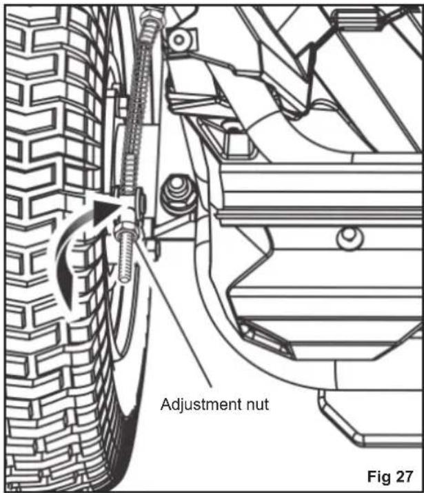
Being able to stop the mower properly is critical to mowing safety. If the mower travels farther before stopping when you step on the brake pedal, the brakes may need adjusting.
To test:
- Stop the product on a level surface and engage the parking brake.
- Set the direction control switch in neutral (N) position.
- Stand behind the mower and try to push it forward. If the rear tyres turn, the brakes need to be tightened.
To tighten:
- Locate the brake adjustment nuts on the interior side of each of the rear wheels.
- Turn each adjustment nut 1/4 turn clockwise, then try again to push the mower.
- Continue rotating each nut 1/4 turn and testing until the mower can no longer be moved by pushing.
After final adjustment, test the brakes by driving the mower at normal speed on flat ground to be sure the mower stops quickly when the brake pedal is pressed.
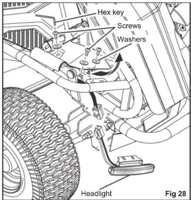
REPLACING THE HEADLIGHTS
See fig. 28
Contact an authorised service centre to order a new headlight.
- Stop the product on a level surface, and engage the parking brake.
- Turn off the product, and remove the start key.
- Remove and set aside the hex head screw and flat washer holding the mower floor panel in place.
- Lift floor panel slightly to access the two hex head screws and flat washers securing the headlight in place. Remove screws and washers and set aside.
- Disconnect the old headlight and discard.
- Connect the new headlight, and reinstall and securely tighten the washers and screws.
- Lower the floor panel, and reinstall the washer and screw to secure.
LEVELLING THE CUTTING DECK
See fig. 29 - 30
If your lawn appears unevenly cut after using the mower, the cutting deck may need adjusting. Before deciding that levelling the cutting deck is necessary, make sure that the tyres are properly inflated to the recommended pressure when mowing. Over-inflated or under-inflated tyres can affect the
appearance of the cut, and proper inflation of the tyres may be all that is needed to resolve uneven cutting issues.
NOTE: Always check side-to-side alignment and adjust as needed before measuring and adjusting front to back.
Before beginning:
- Make sure that the direction control switch is in the neutral (N) position and the blade engage knob is down.
- Turn off the product, engage the parking brake, and remove the start key.
- Set the cutting deck to the maximum height.
To make side-to-side adjustment:
- Position the blades so that the ends point toward the sides of the mower.
-
On the outside edge of each blade, measure the distance from the bottom edge of the side of the blade to the ground. If the distance between the two sides is greater than 0.32 cm (1/8 in.), a side-to-side adjustment is necessary.
-
On the side you wish to adjust, loosen the jam nuts as shown.
-
Turn the adjustment nuts clockwise to raise or counterclockwise to lower the side of the cutting deck. Each full turn of the adjustment nut will change the deck height approximately 0.48 cm (3/16 in.).
NOTE: If raising the side, you will need to turn the top adjustment nut first. If lowering, turn the bottom nut first.
-
Measure the distance between the blade and ground again. Continue to adjust and measure until the difference between the distance on each side is 0.32 cm (1/8 in.) or less.
-
Proceed to front-to-back adjustment or retighten jam nuts to secure.
To make front-to-back adjustment:
NOTE: Always level the deck side to side before making a front to back adjustment.
- Position the blade nearest the side discharge chute so that the ends now point toward the front and back of the mower.
-
Measure the distance from the tip of the blade to the ground. For best results, the front tip of the blade should be from 0.32 cm. to 0.95 cm. (1/8 in. to 3/8 in.) lower than the rear tip.
-
If front-to-back adjustment is needed, turn the adjustment nuts clockwise to raise or counterclockwise to lower the back of the cutting deck. Each full turn of the adjustment nut will change the deck height approximately 0.32 cm. (1/8 in.).
NOTE: Make sure to turn the adjustment nuts on both sides equally to prevent throwing the side-to-side measurement off again.
-
Measure the distance between the blade and ground again to verify that the front tip is 0.32 cm. to 0.95 cm. (1/8 in. to 3/8 in.) lower than the rear tip. If not, continue to adjust and measure until they are.
-
Without moving the adjustment nuts, retighten the jam nuts to secure the adjustment nuts in place.
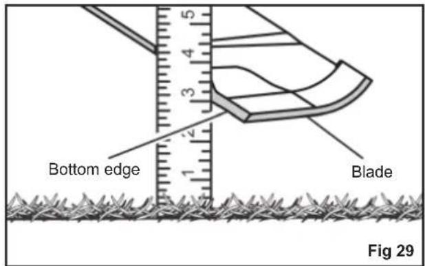
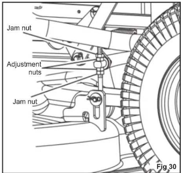
REPLACING THE BATTERIES
See fig. 31 - 36
NOTE: Use only RYOBI ride-on mower lead-acid batteries, part number 5131042607.
The mower operates on four 12-volt batteries connected in series. If replacing one or more of the batteries, always replace them using batteries of the same type with equal voltage and capacity.
WARNING
Use only original lead-acid batteries when replacing.
Never mix different makes and sizes of batteries in the series. Doing so will eventually cause damage to the batteries and may also damage the mower.
WARNING
Do not open or damage the batteries. Released electrolyte is corrosive and may cause damage to the eyes or skin. It may be toxic if swallowed.
Do not incinerate the battery. The batteries could explode. Check with local codes for possible special disposal instructions.
When batteries are not in use, keep it away from other metal objects like, paper clips, coins, keys, nails, screws, or other small metal objects, that can make a connection from one terminal to another. Shorting the battery pack terminals together may cause sparks, burns, fire or explosion.
Exercise care in handling batteries in order not to short the battery with conducting materials such as rings, bracelets, and keys. The battery or conductor may overheat and cause burns.
- Stop the product on a level surface, and engage the parking brake.
- Turn off the product, and remove the start key.
- Tip over the mower seat.
-
Push the two tabs on each side of the cable cover, lift up the cover, and turn it to one side.
-
Remove and set aside the hex head bolt that secures the battery tray in place.
- Disconnect the battery quick-connect plug. This plug connects the batteries to the mower.
- Remove the four screws that secure the battery compartment cover in place.
- Disconnect the thermistor plug. The plug connects the batteries to the charging port.
- Remove the two flange nuts and flange bolts that secure the front of the battery tray in place.
- Pull out the battery tray, resting the end outside the mower on a stable surface that can support a minimum weight of 136.1 kg. (300 lb.).
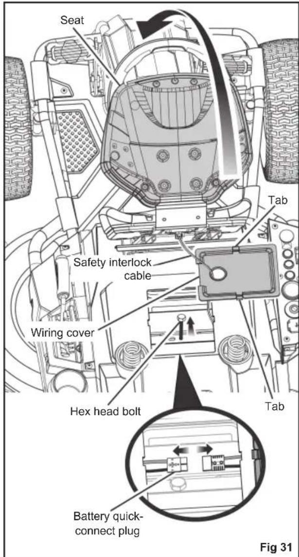
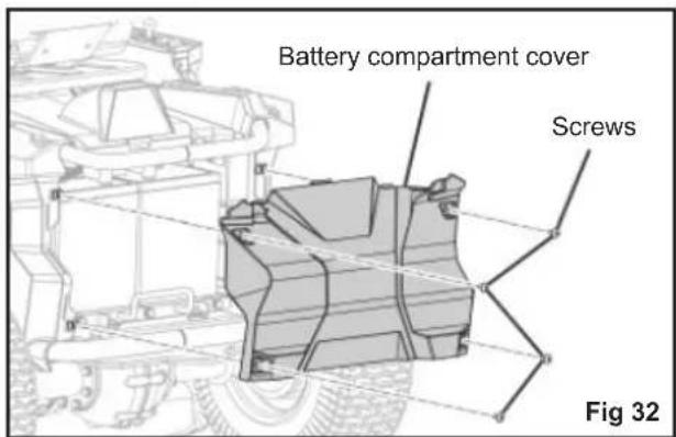
WARNING
The battery tray is very heavy and require at least two people to extend. We recommend the use of a hydraulic tabletype cart (or similar device) to extend the tray. Failure to properly extend and support the battery tray could result in serious personal injury, as well as damage to the mower.
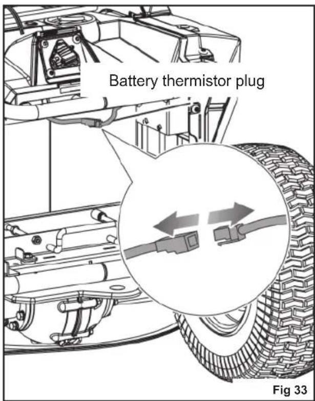
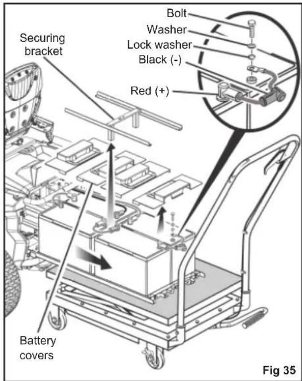
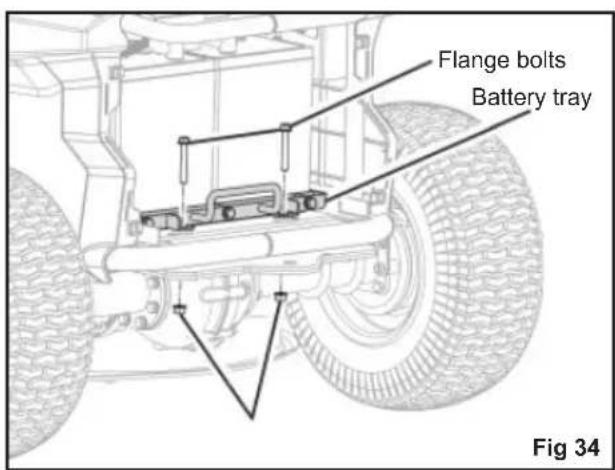
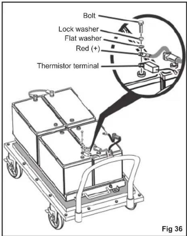
WARNING
Under abusive conditions, liquid may be ejected from the batteries; avoid contact. If contact accidentally occurs, flush with water. If liquid comes in contact with eyes, additionally seek medical help. Liquid ejected from the battery may cause irritation or burns.
- Lift the battery securing bracket off the batteries, and set aside.
- Remove and set aside the battery covers for the battery or batteries being replaced.
- Disconnect the battery or batteries that need to be replaced.
Disconnect the negative (black) cable first, then the positive (red) cable. Be careful not to short across the terminals.
NOTE: When disconnecting the rear cables, take note of the position of the battery thermistor terminal on the positive post. Make sure to reinstall the terminal in the same location. -
Replace the battery or batteries as needed and reinstall cables. Connect the positive (red) cable first, then the negative (black) cable, being careful not to short across the terminals.
-
Reinstall the battery covers and the battery securing bracket.
- Push the battery tray back inside the mower just enough to allow you to reconnect the battery quick-connect plug.
NOTE: To gain enough leverage to reconnect, it is often easier to connect from the battery compartment area rather than the area under the seat. - Once the batteries are reconnected to the mower, push the battery tray fully back inside the mower.
- Reinstall the flange bolts and flange nuts to secure outside edge of battery tray. Tighten securely.
- Reinstall the hex head bolt to secure battery tray in place. Tighten securely.
- Connect the battery thermistor.
- Replace the battery compartment cover, and reinstall hardware to secure.
NOTE: Make sure that the tabs on the battery compartment cover are seated in the slots on the mower top and side panels before tightening the screws. - Reinstall wiring cover, and push down until it latches securely in place, then lower the seat.
NOTE: Always ensure that the safety interlock cable connection is still fully seated when replacing the wiring cover.
NOTE: Always abide by the safety warnings provided with the battery. Dispose of old battery according to local and state regulations.
STORING THE PRODUCT
The following steps should be taken before storing the product:
■ Park the mower on a level surface, and engage the parking brake.
■ Remove any build-up of grass and leaves on or around the motor cover. Wipe the product clean with a dry cloth. Do not use water to clean the product.
■ Plug the product up to charge for the entire time of storage.
NOTE: If it is not possible to leave the mower charger connected during storage, charge the batteries at least once a month during storage. The batteries charge best at temperatures from 0 °C to 40 °C.
■ Store the product in a clean, dry place that is inaccessible to children. Do not store near any appliance that operates with flame such as a gas water heater, clothes
dryer, or furnace.
NOTE: Do not leave the start key in the product during storage.
- Keep the product away from corrosive agents such as garden chemicals and deicing salts.
PREPARING FOR USE AFTER STORAGE
The following steps should be taken before using the product after it has been stored:
■ Review maintenance chart.
■ Fully charge the batteries.
■ Check tyre pressure and inflate as needed.
■ Briefly drive the product and check all systems and components to ensure they are functioning correctly.
MAINTENANCE SCHEDULE
| Inspect before each use | Every 25 hours | Every 50 hours or yearly | Before storage | Once a month during storage | |
| Check brake operation | ■ | ||||
| Check tyre pressure | ■ | ||||
| Check side discharge chute and operator presence safety interlock systems | ■ | ||||
| Check for loose fasteners | ■ | ■ | |||
| Clean debris from the product | ■ | ■ | |||
| Check / Replace mulching blades | ■ | ■ | |||
| Clean battery terminals | ■ | ||||
| Check and charge the battery | ■ | ■ |
NOTE: Maintenance should be performed more frequently when the product is used in dusty areas.
When the product has exceeded the maximum figures specified in the table, maintenance should still be cycled according to the intervals of time or hours stated herein.
If you are unsure how to perform any of the maintenance items listed above, have the product serviced by an authorised service centre only.
ACCESSORIES
| Description Part number | |
| Mulching Blades (for Mulching and Side Discharge) RAC438 (996516) | |
WARNING
Current attachments and accessories available for use with the product are listed above. Do not use any attachments or accessories not recommended by the manufacturer of the product. The use of attachments or accessories not recommended can result in serious personal injury.
REPLACEMENT PARTS
| Description Part number | |
| Mulch cover 5131042540 | |
| Side discharge chute 5131042541 | |
| Front wheels 5131042542 | |
| Rear wheels 5131042543 | |
| Battery 5131042607 |
TROUBLESHOOTING
If these solutions do not solve the problem, have the product serviced by an authorised service centre only.
| Problem Possible cause Solution | ||
| The product does not start. | The battery charge is low. Charge the battery. | |
| The charger is connected to the product. | Disconnect the charger from product. | |
| The start key is not installed or is in the OFF position. | Install the start key, and turn to the ON position. | |
| Poor battery cable connections Check and clean all the battery connections. | ||
| The product will not move. | The start key is not installed or is in the OFF position. | Install the start key, and turn to the ON position. |
| The parking brake is engaged. Disengage the parking brake. | ||
| The direction control switch is in the neutral (N) position. | Place the direction control switch in the desired direction (forward or reverse). | |
| The brake pedal is pressed and/or accelerator pedal is not pressed. | Release the brake pedal, and step on the accelerator pedal. | |
| The charger is connected to the product. | Disconnect the charger from product. | |
| The product is cutting grass unevenly. | The tyre pressure is uneven. Check the tyre pressure in all four tyres. | |
| The mower deck is not level. Perform cutting deck level adjustment. | ||
| The blade is worn, bent, loose, or dull. | Replace the blade. | |
| There is build-up of debris under the product. | Clean underside of the mower deck. | |
| The mowing speed is too fast. Mow at a slower speed. | ||
| The product is not mulching properly. | There are wet grass clippings sticking to the underside of the deck. | Wait until the grass dries before mowing. |
| The grass is too high. Mow once at a high cutting height, then mow again at the preferred height. | ||
| The blade is worn, bent, loose, or dull. | Replace the blade. | |
| The mowing speed is too fast. Mow at a slower speed. | ||
| The product is vibrating at a higher speed. | The blade is unbalanced, loose, or excessively or unevenly worn. | Replace the blade. |
| The motor shaft is bent. Stop the motor, and remove the start key. Inspect the product for damage. Have the product serviced by an authorised service centre before restarting. | ||
| Poor grass discharge. | The side discharge chute or opening is plugged. | Clean the side discharge chute and opening. |
| The grass is wet. Allow grass to dry before mowing. | ||
| The mowing speed is too fast. Mow at a slower speed. | ||
| The grass is too high. Mow once at a high cutting height, then mow again at the desired height. | ||
| The motor stops while cutting. | The cutting height is set too low. Raise the cutting height. | |
| The battery charge is low. Charge the battery. | ||
| The blades do not rotate. | The battery charge is low. Charge the battery. | |
| The side discharge interlock switch is not pressed by the side discharge chute. | Push down the side discharge chute, and make sure that it fully presses the side discharge interlock switch. | |
| The blade engage knob is down. Pull up the blade engage knob. | ||
| The operator is not fully seated. Fully sit down on the seat. | ||
| There is build-up of debris under mower. | Clean the underside of the mower deck. | |
| The blades do not rotate while moving in reverse. | The reverse mode option is off. Press the reverse mode button to activate reverse mode. | |
| The blade engage knob is down. Pull up the blade engage knob. | ||
| The product won't reach full speed. | The battery charge is low. Charge the battery. | |
| The blades continue to turn after the operator leaves the seat without engaging the parking brake. | The safety interlock system is not functioning correctly. | Ensure that the safety interlock system seat plug is fully connected. If the blades still won't stop, have the product serviced by an authorised service centre only. |
| The headlights are not working. | The headlights are off. Press the headlight button to turn on the headlights. | |
| The headlights are damaged. Replace the headlights. | ||
| The battery will not charge. | The battery cells are bad. Replace the battery. | |
| The cable connections are poor. Check and clean all the battery connections. | ||
FREQUENTLY ASKED QUESTIONS
■Should the mower remain plugged into the charger when not in use?
– Yes, continually charge the mower when not in use.
■ What is the recommended tyre pressure, and how often should I check the air pressure in the tyres?
- For best performance, the tyre pressure should be 1.6 bar. Check the tyre pressure before each use.
■ What can cause the blades to stop during use?
- Check the battery level indicator. The deck motor turns off when the battery power gets low to allow you enough time to drive back to the charging location. Drive back and charge the battery immediately.
- If the battery level is not low, slow down or raise the cutting deck to a higher level. High load applications can also cause one or both deck motors to stop.
- Check that the side discharge chute is properly closed. Push down the side discharge chute, and make sure that it fully presses the side discharge interlock switch.
■ When coasting downhill, why does the mower sometimes accelerates and sometimes does not?
- For your safety and better performance, the mower is designed to automatically limit its speed when travelling on a slope, which may cause fluctuations in speed.
■ Why does the mower make a beeping sound when I drive in reverse?
– To alert anyone nearby of the mower's location.
■ When operating the mower, how do I bring the mower to a complete stop?
- To stop the mower, step on the brake pedal on the operator's left side. This product is not a hydrostatic drive.
■ Why does the mower make a beeping sound when I leave the seat?
- The parking brake has not been engaged or the start key is still installed and in the ON position. Always remove
the key when the mower is not in use.
■ When should I use the parking brake?
– Always engage the parking brake before getting off the mower.
■ Can I rinse off the mower deck with a garden hose?
- Do not clean the product with water. Use a blower or air compressor to clean it.
SYMBOLES APPLIQUÉS SUR LE PRODUIT


Alerte de sécurité
natural_image
Technical line drawing of a mechanical assembly with structural supports and a top-down view of a vehicle (no text or symbols present)LISTE DES PIÈCES DÉTACHÉES
natural_image
Line drawing of a small office chair with open lid and seat rack (no text or symbols)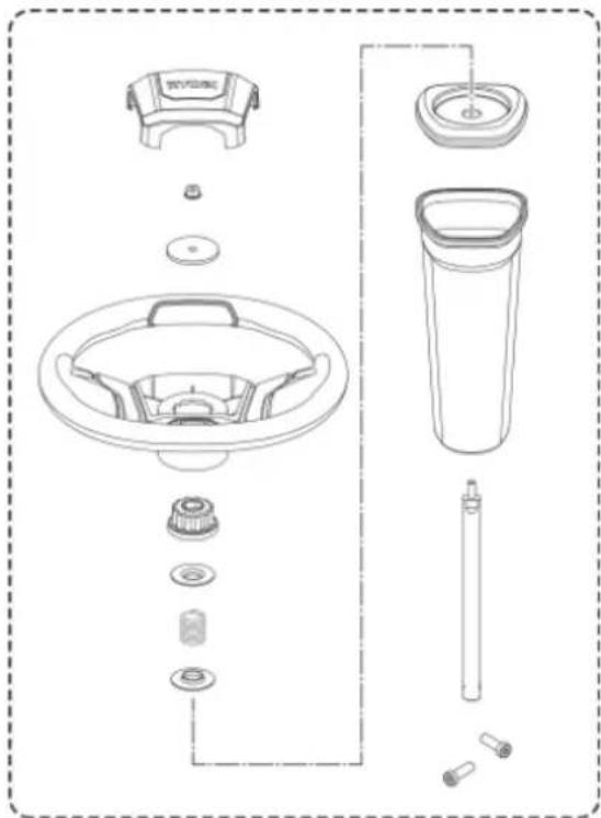
natural_image
Exploded view diagram of a kitchen sink and toilet system (no text or labels)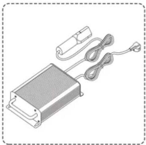
natural_image
Illustration of a heat exchanger with cooling unit, cable, and power outlet (no text or symbols)
natural_image
Simple line drawing of a curved pipe or tube with no text or symbols
natural_image
Simple line drawing of a key with a handle and spout, enclosed in a dashed border (no text or symbols)AVERTISSEMENT
CHARGEMENT DU PRODUIT
Voir figures 7 - 8.
natural_image
Mechanical assembly diagram showing a component being processed with a valve, including a magnified inset of the valve assembly (no text or symbols present)VÉRIFICATION DU SYSTÈME DE VERROUILLAGE DE SÉCURITÉ DE PRÉSENCE DE L'OPÉRATEUR
Voir figure 10.
natural_image
Diagram of a vehicle's rear bumper with a curved arrow indicating motion or change, no text or symbols presentSERRAGE DU FREIN DE STATIONNEMENT
Voir figure 13.
natural_image
Technical line drawing of a mechanical assembly with a downward arrow indicating a component (no text or symbols present)natural_image
Mechanical assembly diagram showing a component with circular features and a downward arrow indicating a process (no text or symbols present)natural_image
Technical line drawing of a mechanical assembly with a central component and an upward arrow indicator (no text or symbols present)AVERTISSEMENT
natural_image
Two side-by-side illustrations of a motor stroller with checkmark and cross symbols indicating correct and incorrect states (no text or labels)AVERTISSEMENT
natural_image
Line drawing of a person riding an electric scooter on a slope, labeled 'Fig. 20' (no text or symbols on the diagram itself)TRANSPORT DE L'APPAREIL
Voir figure 21.
AVERTISSEMENT
natural_image
Line drawing of a person using a mobility vehicle on a ramp next to a vehicle (no text or symbols)Fig. 21
ENTRETENIR LE PRODUIT
AVERTISSEMENT
REEMPLACEMENT DES PHARES
Voir figure 28.
SYMBOLE AUF DEM PRODUKT


Sicherheitswarnung
natural_image
Technical line drawing of a mechanical assembly with structural supports and a central vehicle (no text or symbols)LISTE LOSER TEILE
natural_image
Line drawing of a small office chair with open lid and seat, no text or symbols present
natural_image
Exploded view diagram of a kitchen sink and toilet system (no text or labels)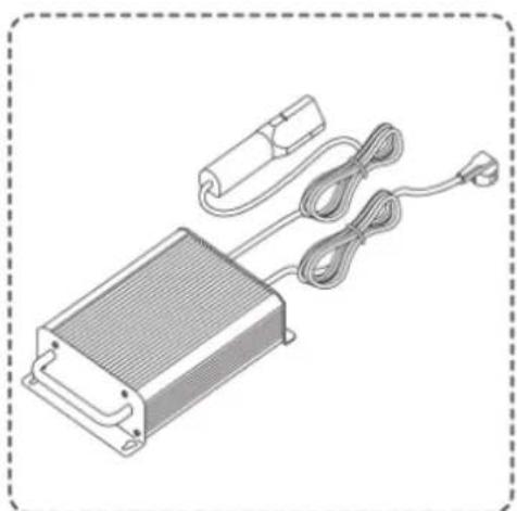
natural_image
Illustration of a rectangular electronic device with attached cable and connector (no text or symbols)
natural_image
Simple line drawing of a curved, segmented object with no text or symbols
natural_image
Line drawing of a key with a handle and keyhole, enclosed in a dashed border (no text or symbols)WARNUNG
LADEN SIE DAS PRODUKT AUF
natural_image
Mechanical assembly diagram showing a component with gear and housing, including a close-up inset of a connector (no text or symbols)TESTENDESSICHERHEITSSPERRSYSTEM FÜR DEN BEDIENER
Siehe Abbildung 10.
MACHEN SIE SICH MIT IHREM PRODUKT VERTRAUT
Siehe Abbildung 11.
natural_image
Diagram of a vehicle's rear cover with gear and wheel components, showing a curved arrow indicating motion (no text or symbols present)FESTSTELLBREMSE ANZIEHEN
Siehe Abbildung 13.
natural_image
Mechanical component diagram showing a valve assembly with a downward arrow indicating force or direction (no text or symbols present)natural_image
Mechanical assembly diagram showing a component with circular features and a downward arrow indicating a process (no text or symbols present)natural_image
Technical line drawing of a mechanical assembly with a central component and an upward arrow indicating motion (no text or symbols)WARNUNG
natural_image
Side-by-side comparison of a motor stroller with checkmark and cross symbols indicating correct and incorrect states (no text or labels present)WARNUNG
natural_image
Line drawing of a person riding an electric scooter on a slope, labeled 'Abb. 20' (no other text or symbols)TRANSPORT DES PRODUKTS
Siehe Abbildung 21.
WARNUNG
natural_image
Line drawing of a person riding a car on an inclined ramp next to a vehicle (no text or symbols)DAS GERÄT WARTEN
WARNUNG
SYMBOLER PÅ PRODUKTET


Sikkerheds Varsel
natural_image
Technical line drawing of a mechanical assembly with structural supports and a central vehicle component (no text or symbols)LISTE OVER L∅SE DELE
natural_image
Line drawing of a small office chair with open lid and seat, no text or symbols present
natural_image
Exploded view diagram of a kitchen sink and toilet system (no text or labels)
natural_image
Illustration of an electronic device with a heat exchanger, cable, and power plug (no text or symbols)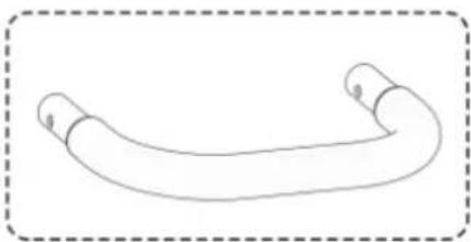
natural_image
Simple line drawing of a curved pipe or tube with two ends, enclosed in a dashed border (no text or symbols)
natural_image
Simple line drawing of a key with a handle and spout, enclosed in a dashed border (no text or symbols)ADVARSEL
INSTALLATION AF SÆDET
Se figur 3.
OPLADNING AF PRODUKTET
Se figur 7 - 8.
natural_image
Mechanical assembly diagram showing a component being processed with a close-up inset (no text or symbols)TEST AF SIKKERHEDSLÅSESYSTEM FOR TILSTEDEVÆRELSE AF OPERAT∅R
Se figur 10.
natural_image
Diagram of a vehicle's roof structure with gear and wheel components, showing a curved arrow indicating motion (no text or symbols present)AKTIVERING AF PARKERINGSBREMSEN
Se figur 13.
Sådan aktiveres parkeringsbremsen:
natural_image
Diagram of a car dashboard with directional arrows indicating rotation and adjustment (no text or symbols)natural_image
Illustration of a person using a Baktilstand electric vehicle in a grassy outdoor setting (no text or symbols on the diagram itself)Betjening i baktilstand:
ADVARSEL
- Tryk ned på klingens aktiveringsgreb for at stoppe klingerne.
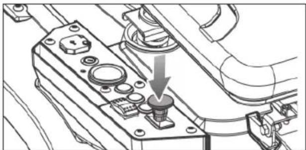
natural_image
Mechanical assembly diagram showing a component with a downward arrow indicating a specific part (no text or symbols present)- Tryk på knappen for baktilstand.
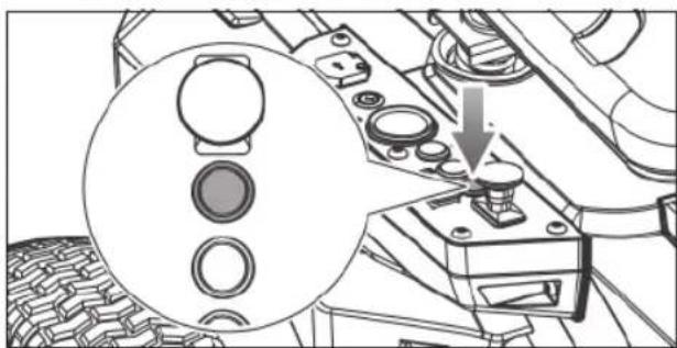
natural_image
Technical diagram of a mechanical assembly with circular components and a downward arrow indicating a process (no text or symbols present)natural_image
Mechanical assembly diagram showing a valve mechanism with an upward arrow (no text or symbols present)ADVARSEL
natural_image
Two identical line drawings of a motor or scooter with no text, numbers, or symbols.- Sæt retningsknappen i stillingen frigear (N).
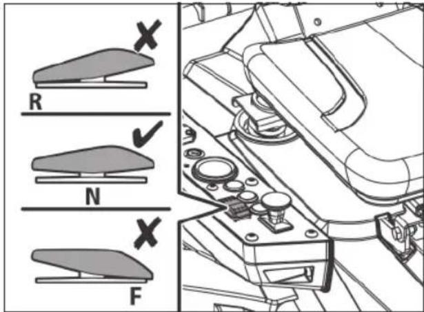
ADVARSEL
natural_image
Line drawing of a person riding a motorcyclist on a slope, labeled 'Fig. 20' (no text or symbols on the diagram itself)TRANSPORT AF PRODUKTET
Se figur 21.
ADVARSEL
natural_image
Line drawing of a person riding a motorized vehicle next to a vehicle (no text or symbols)Fig. 21
VEDLIGEHOLDELSE AF PRODUKTET
ADVARSEL
OPBEVARING AF PRODUKTET
OFTE STILLEDE SP∅RGSMÅL
TRANSPORT OCH FÖRVARING
SYMBOLER PÅ PRODUKTEN

Säkerhetsvarning

natural_image
Technical line drawing of a mechanical assembly with structural supports and a central vehicle (no text or symbols)LISTA MED LÖSA DELAR
natural_image
Line drawing of a small office chair with open lid and seat, no text or symbols present
natural_image
Exploded view diagram of a kitchen sink and toilet system (no text or labels)
natural_image
Illustration of an electronic device with a heat exchanger, coiled cable, and power plug (no text or symbols)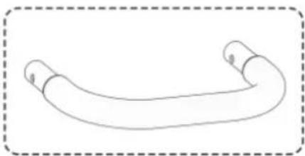
natural_image
Simple line drawing of a curved pipe or tube with two ends, enclosed in a dashed border (no text or symbols)
natural_image
Simple line drawing of a key with a handle and spout, enclosed in a dashed border (no text or symbols)WARNING
natural_image
Mechanical assembly diagram showing a component being inserted into a vehicle chassis, with an inset close-up of the plug assembly (no text or symbols present)TESTA OPERATÖRENS NÄRVARO MED SÄKERHETSPÄRRSYSTEM
Se bild 10.
natural_image
Mechanical component diagram showing a moving part with a curved arrow indicating motion (no text or symbols present)KOPPLA PÅ PARKERINGSBROMSEN
Se bild 13.
natural_image
Mechanical assembly diagram showing a valve or knob inserted into a housing component with a downward arrow indicating motion (no text or symbols present)natural_image
Mechanical assembly diagram showing a valve mechanism with a magnified inset (no text or symbols)natural_image
Technical line drawing of a mechanical assembly with a central component and an upward arrow indicating motion (no text or symbols)natural_image
Illustration of a person using a motor cab to lift a vehicle, with a magnified inset showing the wheel assembly (no text or symbols)WARNING
natural_image
Two side-by-side illustrations of a motor stroller with checkmark and cross symbols indicating correct and incorrect states (no text or labels)WARNING
natural_image
Line drawing of a person riding a motorcyclist on a slope, labeled 'Fig. 20' (no text or symbols on the diagram itself)TRANSPORT AV PRODUKTEN
Se bild 21.
natural_image
Line drawing of a person riding a car on an inclined ramp next to a vehicle (no text or symbols)UNDERHÅLL AV PRODUKTEN
WARNING
BYT UT STRÅLKASTARNA
Se bild 28.
natural_image
Line drawing of a small office chair with open lid and seat, no text or symbols present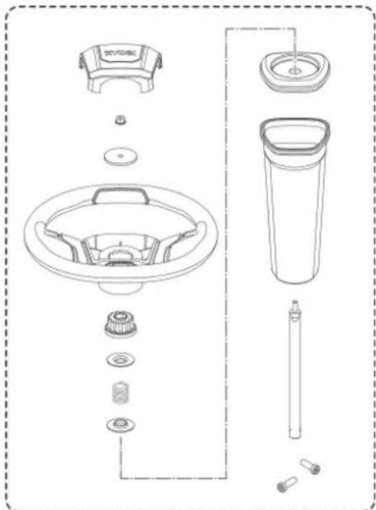
natural_image
Exploded view diagram of a washing machine showing key components like fan, drum, and bulb (no text or labels)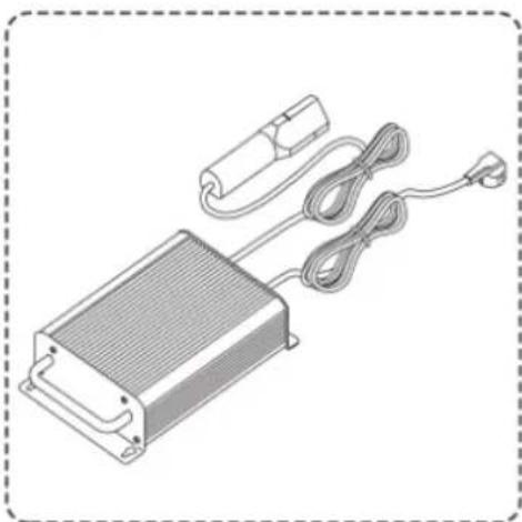
natural_image
Illustration of a rectangular electronic device with a coiled cable and power connector (no text or symbols)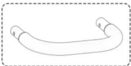
natural_image
Simple line drawing of a curved pipe or tube with no text or symbols
natural_image
Line drawing of a key with a handle and spout, enclosed in a dashed border (no text or symbols)VAROITUS
natural_image
Mechanical assembly diagram showing a component being processed with a tool, including a magnified inset of the tool (no text or symbols present)natural_image
Mechanical component diagram showing a car interior with tire tracks and wheels, no text or symbols presentKÄSIJARRUN KYTKEMINEN PÄÄLLE
Katso kuvaa 13.
natural_image
Mechanical assembly diagram showing a component with a downward arrow indicating a specific part (no text or symbols present)natural_image
Technical diagram of a mechanical assembly with circular components and a downward arrow indicating a process (no text or symbols present)natural_image
Technical line drawing of a mechanical assembly with a central component and an upward arrow indicator (no text or symbols present)VAROITUS
natural_image
Side-by-side comparison of a motor stroller with checkmark and cross symbols indicating correct and incorrect states (no text or labels)VAROITUS
natural_image
Line drawing of a person riding an electric scooter on a slope, labeled 'Kuva 20' (no other text or symbols)TUOTTEEN KULJETTAMINEN
Katso kuvaa 21.
natural_image
Line drawing of a person riding a motorized vehicle on an inclined ramp, with a truck nearby (no text or symbols)AJOLEIKKURIN HUOLTO
VAROITUS
ARBEIDSOMRÅDETS SIKKERHET
SYMBOLER PÅ PRODUKTET


Sikkerhetsalarm
SYMBOLER I DENNE MANUALLEN

natural_image
Technical line drawing of a mechanical assembly with structural supports and a top-down view of a vehicle (no text or symbols present)LISTE OVER L∅SE DELER
-
Lader x 1
-
Støtfanger x 1
-
Zündschlüssel x3
ADVARSEL
natural_image
Line drawing of a medical or rehabilitation chair with open lid and seat (no text or symbols)
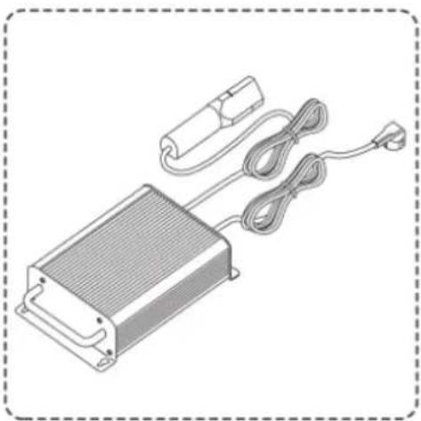
natural_image
Illustration of an electronic device with a heat exchanger, coiled cable, and power plug (no text or symbols)
natural_image
Simple line drawing of a curved pipe or tube with two ends, enclosed in a dashed border (no text or symbols)
natural_image
Simple line drawing of a key with a handle and spout, enclosed in a dashed border (no text or symbols)ADVARSEL
natural_image
Mechanical assembly diagram showing a component being processed with a tool, including a magnified inset of the tool (no text or symbols present)TEST D∅DMANNSFUNKSJONEN
Se fig. 10.
KJENN PRODUKTET DITT
Se fig. 11.
natural_image
Mechanical component diagram showing a meshed part with a curved arrow indicating motion or force (no text or symbols)SETTE PÅ HÄNDBREMSEN
Se fig. 13.
INNSTILLING AV KLIPPERDEKKETS H∅YDE
Se fig. 15.
natural_image
Technical line drawing of a mechanical assembly with a downward arrow indicating a component (no text or symbols present)- Trykk på reversmodus-knappen.
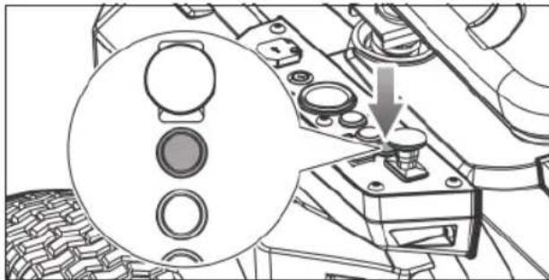
natural_image
Mechanical component diagram showing a dial indicator and mechanical parts (no text or symbols)natural_image
Technical line drawing of a mechanical assembly with a central component and an upward arrow indicator (no text or symbols present)ADVARSEL
natural_image
Line drawing of a scooter with open lid and wheels, no text or symbols present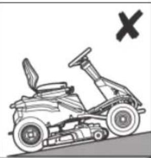
natural_image
Illustration of a motorized vehicle with a cross symbol (no text or labels)- Tråkk på fotbremsen og sett på håndbremsen.
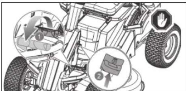
ADVARSEL
natural_image
Line drawing of a person riding a motorized vehicle on a slope, labeled 'Fig. 20' (no text or symbols on the diagram itself)TRANSPORT AV PRODUKTET
Se fig. 21.
ADVARSEL
natural_image
Line drawing of a person riding a car on an inclined ramp next to a vehicle (no text or symbols)MASKINEN VEDLIKEHOLDES
ADVARSEL
OFTE STILTE SP∅RSMÅL
In addition to any statutory rights resulting from the purchase, this product is covered by a warranty as stated below.
- The warranty period is 24 months for consumers and commences on the date when the product was purchased. This date has to be documented by an invoice or other proof of purchase. The product is designed and dedicated to consumer and private use only. So there is no warranty provided in case of professional or commercial use.
- There is a possibility to extend for a part of the range of power tools (AC/DC) the warranty period over the period described above using the registration on the www.ryobitools.eu website. The eligibility of products for extended warranty is clearly displayed in stores and / or on packaging and is contained within the product documentation. The end user is required to register his/her newly-acquired products online within 30 days from the date of purchase. The end user may register for the extended warranty in his/her country of residence if listed on the online registration form where this option is valid. Furthermore, end users must give their consent to the storage of their personal data that is required to be entered online. They must also accept the terms and conditions. The registration confirmation receipt, which is sent out by e-mail, and the original invoice showing the date of purchase will serve as proof of the extended warranty.
-
The warranty covers all defects of the product during the warranty period due to faults in workmanship or material at the purchase date. The warranty is limited to repair and/or replacement and does not include any other obligations including but not limited to incidental or consequential damages. The warranty is not valid if the product has been misused, used contrary to the instruction manual, or has been incorrectly connected to a power supply. This warranty does not apply to:
-
any damage to the product that is the result of improper or lack of maintenance
-any product that has been altered or modified
– any product where original identification (trade mark, serial number) markings have been defaced, altered or removed
-any damage caused by non-observance of the instruction manual
-any product not displaying the CE approval mark on the rating pla
– any product that has been attempted to be repaired by a non-authorised warranty service centre or without prior authorisation by Techtronic Industries - any product connected to improper power supply (amps, voltage, frequency)
- any product used with inappropriate fuel mixture (fuel, oil, ratio of oil/ fuel mixture)
- any damage caused by external influences (water, chemical, physical, shocks) or foreign substances
-normal wear and tear spare parts
-inappropriate use, overloading of the tool
-use of non-approved accessories or parts
-Any periodic adjustments to or maintenance cleaning of carburettors
- Components (parts and accessories) subject to natural wear and tear, including but not limited to bump knobs, drive belts, clutch, blades of hedge trimmers or lawn mowers, harness, cable throttle, carbon brushes, power cord, tines, felt washers, hitch pins, blower fans, blower and vacuum tubes, vacuum bag and straps, guide bars, saw chains, hoses, connector fittings, spray nozzles, wheels, spray wands, inner reels, outer spools, cutting lines, spark plugs, air filters, gas filters, mulching blades, etc.
-
For servicing, the product must be sent or presented to a RYOBI authorised service station listed for each country in the following list of service station addresses. In some countries your local RYOBI dealer undertakes to send the product to the RYOBI service organisation. When sending a product to a RYOBI service station, the product should be safely packed without any dangerous contents such as petrol, marked with sender's address and accompanied by a short description of the fault.
-
A repair / replacement under this warranty is free of charge. It does not constitute an extension or a new start of the warranty period. Exchanged parts or products become our property. In some countries delivery charges or postage will have to be paid by the sender. Your statutory rights arising from the purchase of the product remain unaffected.
- This warranty is valid in the European Community, Switzerland, Iceland, Norway, Liechtenstein, Turkey and Russia. Outside these areas, please contact your authorised RYOBI dealer to determine if another warranty applies.
AUTHORISED SERVICE CENTRE
To find an authorised service centre near you, visit http://uk.ryobitools.eu/header/service-and-support/service-agents.
FR RYOBI® CONDITIONS D'APPLICATION DE LA GARANTIE
DECLARATION OF CONFORMITY
Techtronic Industries GmbH
Max-Eyth-Straße 10, 71364 Winnenden, Germany
Herewith we declare that the product
Ride-On Mower
Brand: RYOBI
Model number: RM480e
Serial number range: 47512301000001 - 47512301999999
is in conformity with the following European Directives and harmonised standards
2006/42/EC, 2014/30/EU, 2000/14/EC, 2005/88/EC, EN ISO 12100: 2010,
EN 62841-1: 2015, EN ISO 5395-1: 2013+A1:2018,
EN ISO 5395-3: 2013+A1:2017+A2:2018.
EN 55014-1:2017, EN 55014-2:2015
Measured sound power level: 99.1 dB(A)
Guaranteed sound power level: 100 dB(A)
Conformity assessment method to Annex V Directive 2000/14/EC amended by 2005/88/EC.
The notified body involved:
No.0197 – TÜV Rheinland LGA Products GmbH
Tillystraße 2 - 90431 Nürnberg – Germany»

CE
Todd Chipner
Sr. Director, CPT Quality and Asia Regulatory & Safety
Winnenden, Dec. 30, 2019
Authorised to compile the technical file:
Alexander Krug, Managing Director
Techtronic Industries GmbH
Max-Eyth-Straße 10, 71364 Winnenden, Germany

Max-Eyth-Straße 10, 71364 Winnenden, Germany
Winnenden, Dec. 30, 2019
Max-Eyth-Straße 10, 71364 Winnenden, Germany

DÉCLARATION DE CONFORMITÉ
Techtronic Industries GmbH
Max-Eyth-Straße 10, 71364 Winnenden, Germany
Winnenden, Dec. 30, 2019
Max-Eyth-Straße 10, 71364 Winnenden, Germany

OVERENSSTEMMELSESERKLÆRING
Techtronic Industries GmbH
Max-Eyth-Straße 10, 71364 Winnenden, Germany
Vi erklærer hermed, at produktet
Winnenden, Dec. 30, 2019
Max-Eyth-Straße 10, 71364 Winnenden, Germany


KONFORMITETSDEKLARATION
Techtronic Industries GmbH
Max-Eyth-Straße 10, 71364 Winnenden, Germany
Winnenden, Dec. 30, 2019
Max-Eyth-Straße 10, 71364 Winnenden, Germany

SAMSVARSERKLÆRING
Techtronic Industries GmbH
Max-Eyth-Straße 10, 71364 Winnenden, Germany
Winnenden, Dec. 30, 2019
Max-Eyth-Straße 10, 71364 Winnenden, Germany

SÄÄNNÖSTEN NOUDATTAMINEN
Techtronic Industries GmbH
Max-Eyth-Straße 10, 71364 Winnenden, Germany
Winnenden, Dec. 30, 2019
Max-Eyth-Straße 10, 71364 Winnenden, Germany

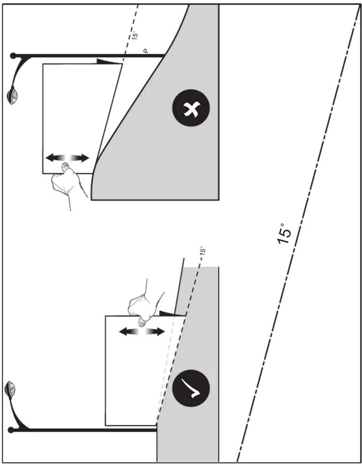
EN RYOBI is a trade mark of Ryobi Limited, and is used under license.
© 2019-20 Techtronic Cordless GP.
© 2019-20 Techtronic Cordless GP.
© 2019-20 Techtronic Cordless GP.
© 2019-20 Techtronic Cordless GP.
© 2019-20 Techtronic Cordless GP.
© 2019-20 Techtronic Cordless GP.
© 2019-20 Techtronic Cordless GP.
© 2019-20 Techtronic Cordless GP.
© 2019-20 Techtronic Cordless GP.
© 2019-20 Techtronic Cordless GP.
© 2019-20 Techtronic Cordless GP.
© 2019-20 Techtronic Cordless GP.
© 2019-20 Techtronic Cordless GP.
© 2019-20 Techtronic Cordless GP.
© 2019-20 Techtronic Cordless GP.
© 2019-20 Techtronic Cordless GP.
© 2019-20 Techtronic Cordless GP.
© 2019-20 Techtronic Cordless GP.
© 2019-20 Techtronic Cordless GP.
HR RYOBI je žig tvrtke Ryobi Limited i koristi se po licenci.
© 2019-20 Techtronic Cordless GP.
© 2019-20 Techtronic Cordless GP.
© 2019-20 Techtronic Cordless GP.
© 2019-20 Techtronic Cordless GP.
© 2019-20 Techtronic Cordless GP.
© 2019-20 Techtronic Cordless GP.


RYOBI®
Techtronic Industries GmbH
Max-Eyth-Straße 10,
71364 Winnenden, Germany


- INTENDED USE
- GENERAL SAFETY WARNINGS
- WARNING
- WORK AREA SAFETY
- ELECTRICAL SAFETY
- PERSONAL SAFETY
- POWER TOOL USE AND CARE
- BATTERY TOOL USE AND CARE
- SERVICE
- PREPARATION
- OPERATION
- ADDITIONAL CHARGER SAFETY WARNINGS
- ADDITIONAL BATTERY SAFETY WARNINGS
- BATTERY PACK REMOVAL AND PREPARATION FOR RECYCLING
- TRANSPORTATION AND STORAGE
- TRANSPORTING LEAD-ACID BATTERIES
- TOWING SAFETY WARNINGS
- MAINTENANCE
- CLEARING BLOCKAGES
- RESIDUAL RISKS
- RISK REDUCTION
- WHAT'S IN THE BOX
- SYMBOLS ON THE PRODUCT
- CAUTION
- SYMBOLS IN THIS MANUAL
- DANGER
- ASSEMBLY
- ASSEMBLY SAFETY RULES
- REQUIRED TOOLS
- UNPACKING
- LOOSE PARTS LIST
- CONNECTING THE BATTERY
- To connect:
- INSTALLING THE SEAT
- INSTALLING THE STEERING COLUMN
- See fig. 4 - 5
- INSTALLING THE BUMPER
- See fig. 6
- CHARGING THE PRODUCT
- For best results:
- To charge:
- FINAL CHECKS
- CHECKING THE TYRE AIR PRESSURE
- CHECKING THE SIDE DISCHARGE CHUTE SAFETY INTERLOCK SYSTEM
- KNOW THE PRODUCT
- ACCELERATOR PEDAL
- BATTERY LEVEL INDICATOR / HOUR METER
- BLADE ENGAGE KNOB
- BRAKE PEDAL
- CHARGER
- CRUISE CONTROL BUTTON
- DECK HEIGHT ADJUSTMENT LEVER
- DIRECTION CONTROL SWITCH
- HEADLIGHT BUTTON
- MEDIA HOLDER
- MULCH COVER
- PARKING BRAKE
- POWER SWITCH WITH START KEY
- SEAT ADJUSTMENT LEVER
- SIDE DISCHARGE CHUTE SAFETY INTERLOCK SYSTEM
- USB PORT
- HITCH PLATE
- INSTALLING THE MULCH COVER
- To engage the parking brake:
- To disengage the parking brake:
- ADJUSTING THE SEAT
- To move the seat:
- SETTING THE CUTTING DECK HEIGHT
- To adjust the cutting deck height:
- SETTING THE CRUISE CONTROL
- To set the cruise control:
- To release the cruise control:
- USING THE PRODUCT
- Mowing:
- Reverse mode operation:
- When mowing is complete:
- MOWING TIPS
- SLOPE OPERATION
- TRANSPORTING THE PRODUCT
- MAINTAINING THE PRODUCT
- General maintenance
- ADJUSTING CUTTING DECK WHEELS
- To adjust the cutting deck wheels:
- REMOVING THE CUTTING DECK
- REPLACING THE CUTTING BLADES
- TYRE MAINTENANCE
- Tyre air pressure
- TYRE REPAIR
- REPLACING TYRES
- To test:
- To tighten:
- REPLACING THE HEADLIGHTS
- LEVELLING THE CUTTING DECK
- Before beginning:
- To make side-to-side adjustment:
- To make front-to-back adjustment:
- REPLACING THE BATTERIES
- STORING THE PRODUCT
- PREPARING FOR USE AFTER STORAGE
- TROUBLESHOOTING
- FREQUENTLY ASKED QUESTIONS
- SYMBOLES APPLIQUÉS SUR LE PRODUIT
- LISTE DES PIÈCES DÉTACHÉES
- AVERTISSEMENT
- CHARGEMENT DU PRODUIT
- VÉRIFICATION DU SYSTÈME DE VERROUILLAGE DE SÉCURITÉ DE PRÉSENCE DE L'OPÉRATEUR
- SERRAGE DU FREIN DE STATIONNEMENT
- TRANSPORT DE L'APPAREIL
- ENTRETENIR LE PRODUIT
- REEMPLACEMENT DES PHARES
- SYMBOLE AUF DEM PRODUKT
- LISTE LOSER TEILE
- WARNUNG
- LADEN SIE DAS PRODUKT AUF
- TESTENDESSICHERHEITSSPERRSYSTEM FÜR DEN BEDIENER
- MACHEN SIE SICH MIT IHREM PRODUKT VERTRAUT
- FESTSTELLBREMSE ANZIEHEN
- TRANSPORT DES PRODUKTS
- DAS GERÄT WARTEN
- SYMBOLER PÅ PRODUKTET
- LISTE OVER L∅SE DELE
- ADVARSEL
- INSTALLATION AF SÆDET
- OPLADNING AF PRODUKTET
- TEST AF SIKKERHEDSLÅSESYSTEM FOR TILSTEDEVÆRELSE AF OPERAT∅R
- AKTIVERING AF PARKERINGSBREMSEN
- Sådan aktiveres parkeringsbremsen:
- Betjening i baktilstand:
- TRANSPORT AF PRODUKTET
- VEDLIGEHOLDELSE AF PRODUKTET
- OPBEVARING AF PRODUKTET
- OFTE STILLEDE SP∅RGSMÅL
- TRANSPORT OCH FÖRVARING
- SYMBOLER PÅ PRODUKTEN
- LISTA MED LÖSA DELAR
- TESTA OPERATÖRENS NÄRVARO MED SÄKERHETSPÄRRSYSTEM
- KOPPLA PÅ PARKERINGSBROMSEN
- TRANSPORT AV PRODUKTEN
- UNDERHÅLL AV PRODUKTEN
- BYT UT STRÅLKASTARNA
- VAROITUS
- KÄSIJARRUN KYTKEMINEN PÄÄLLE
- TUOTTEEN KULJETTAMINEN
- AJOLEIKKURIN HUOLTO
- ARBEIDSOMRÅDETS SIKKERHET
- SYMBOLER I DENNE MANUALLEN
- LISTE OVER L∅SE DELER
- TEST D∅DMANNSFUNKSJONEN
- KJENN PRODUKTET DITT
- SETTE PÅ HÄNDBREMSEN
- INNSTILLING AV KLIPPERDEKKETS H∅YDE
- TRANSPORT AV PRODUKTET
- MASKINEN VEDLIKEHOLDES
- OFTE STILTE SP∅RSMÅL
- AUTHORISED SERVICE CENTRE
- FR RYOBI® CONDITIONS D'APPLICATION DE LA GARANTIE
- DECLARATION OF CONFORMITY
- DÉCLARATION DE CONFORMITÉ
- OVERENSSTEMMELSESERKLÆRING
- KONFORMITETSDEKLARATION
- SAMSVARSERKLÆRING
- SÄÄNNÖSTEN NOUDATTAMINEN
Brand : RYOBI
Model : RM480E
Category : Electric mower