RY72ZTRX107 - Electric mower RYOBI - Free user manual and instructions
Find the device manual for free RY72ZTRX107 RYOBI in PDF.

| Product Type | Electric zero-turn mower |
| Brand | RYOBI |
| Model | RY72ZTRX107 |
| Power Source | Lithium-ion batteries (72 V + 36 V compatible) |
| Battery Type | Rechargeable lithium-ion |
| USB Charging Port | 5 V DC, 2 A max. |
| LCD Display | Yes, for monitoring and function activation |
| Headlights | Front LED, controllable via LCD display |
| Parking Brake | Yes, brake pedal and parking brake |
| Drive System | Intelligent drive with return-to-neutral lever |
| Turning Radius | Zero |
| Blade Engagement | Blade engagement button |
| Turbo Function | Turbo button for grass collection bag (accessory) |
| Cutting Height Adjustment | Adjustment lever with automatic stop pin |
| Seat Suspension | Adjustable (suspension knob) |
| Operator Presence Safety Lockout System | Seat with presence detection, stops blades if operator stands up |
| Side Discharge Chute Lock | Stops blades if chute opens |
| Blade Maintenance | Replacement with original blades; tighten to recommended torque |
| Cleaning | With compressed air or blower; do not use water |
| Tire Pressure | Check before each use; tubeless tires |
| Charging Temperature Range | 10 °C to 38 °C |
| Operating Temperature Range | 0 °C to 40 °C |
| Warranty | 24 months for private use; extension possible via registration |
Frequently Asked Questions - RY72ZTRX107 RYOBI
User questions about RY72ZTRX107 RYOBI
0 question about this device. Answer the ones you know or ask your own.
Ask a new question about this device
Download the instructions for your Electric mower in PDF format for free! Find your manual RY72ZTRX107 - RYOBI and take your electronic device back in hand. On this page are published all the documents necessary for the use of your device. RY72ZTRX107 by RYOBI.
USER MANUAL RY72ZTRX107 RYOBI
natural_image
Close-up of a robotic device with 'RYOY' branding, positioned on a striped textured surface (no readable text beyond branding)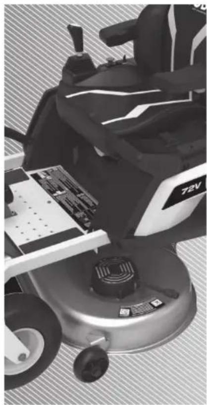
natural_image
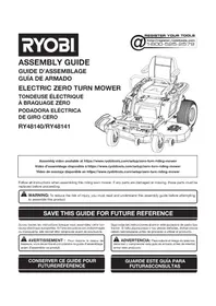
Top-down view of a person using a 72V electric vehicle on a circular base, with visible circuit board and wheels (no text or symbols)
natural_image
Close-up of a black industrial machine with visible tire and handle (no text or symbols)EN FR DE ES IT NL PT DA SV FI NO
RY72ZTRX107

| Important! | It is essential that you read the instructions in this manual before assembling, operating, and maintaining the product. |
| Attention! | Il est essentiel que vous lisiez les instructions contenues dans ce manuel avant d'assembler, d'entretenir et d'utiliser le produit. |
| Achtung! | Es ist wichtig, dass Sie vor Zusammenbau, Wartung und Benutzung des Produktes die Anweisungen in dieser Anleitung lesen. |
| ¡Atención! | Resulta fundamental que lea este manual de instrucciones antes de realizar el montaje, el mantenimiento y de utilizar este producto |
| Attenzione! | E’ importante leggere le istruzioni contenute nel presente manuale prima di montare il prodotto, svolgere le operazioni di manutenzione sullo stesso e metterlo in funzione. |
| Let op! | Het is van essentieel belang dat u de instructies in deze gebruiksaanwijzing leest voor u het product monteert, onderhoudt en gebruikt. |
| Atenção! | É fundamental que leia as instruções deste manual antes da montagem, manutenção e operação do aparelho. |
| OBS! | Det er vigtigt, at man læser instrukserne i denne brugsanvisning, inden man samler, vedligeholder og betjener produktet. |
| Observera! | Det är viktigt att du läser instruktionerna i manualen före montering, användning och underhåll av produkten. |
| Huomio! | On tärkeää, että luet tämän käsikirjan ohjeet ennen tuotteen kokoamista, huoltoa ja käyttöä. |
| Advarsel! | Det er viktig at du leser instruksjonene i denne manualen før sammensetning, vedlikehold og bruk av produktet |
Subject to technical modification | Sous réserve de modifications techniques | Technische Änderungen vorbehalten | Bajo reserva de modificaciones técnicas | Con riserva di eventuali modifiche tecniche | Technische wijzigingen voorbehouden | Com reserva de modificações técnicas | Med forbehold for tekniske ændringer | Med förbehåll för tekniska ändringar | Tekniset muutokset varataan | Med forbehold om tekniske endringer.
Safety, performance, and dependability have been given top priority in the design of your zero-turn mower.
The zero-turn mower is intended for outdoor use only.
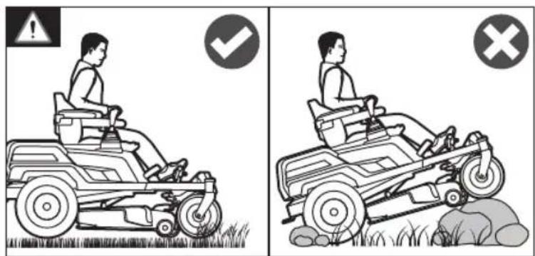
The product is designed for domestic lawn mowing. The cutting blade should rotate approximately parallel to the ground over which it is being wheeled. All four wheels should touch the ground while mowing.
The product is to be used only in domestic application by adults who have received adequate training on the hazards and preventive measures or actions taken while using it. The user must understand the instructions.
Do not use the product for any other purpose.
WARNING! Read all safety warnings, instructions, illustrations and specifications provided with this power tool. Failure to follow all instructions listed below may result in electric shock, fire and/or serious injury.
Save all warnings and instructions for future reference.
The term “power tool” in the warnings refers to your mains-operated (corded) product or battery-operated (cordless) product.
WORK AREA SAFETY
- Keep work area clean and well lit. Cluttered or dark areas invite accidents.
■ Do not operate power tools in explosive atmospheres, such as in the presence of flammable liquids, gases or dust. Power tools create sparks which may ignite the dust or fumes.
- Keep children and bystanders away while operating a power tool. Distractions can cause you to lose control.
ELECTRICAL SAFETY
■ Power tool plugs must match the outlet. Never modify the plug in any way. Do not use any adapter plugs with earthed (grounded) power tools. Unmodified plugs and matching outlets will reduce risk of electric shock.
■ Avoid body contact with earthed or grounded surfaces, such as pipes, radiators, ranges, and refrigerators. There is an increased risk of electric shock if your body is earthed or grounded.
■ Do not expose power tools to rain or wet conditions. Water entering a power tool will increase the risk of electric shock.
■ Do not abuse the cord. Never use the cord for carrying, pulling or unplugging the power tool. Keep cord away from heat, oil, sharp edges, or moving parts. Damaged or entangled cords increase the risk of electric shock.
■ When operating a power tool outdoors, use an extension cord suitable for outdoor use. Use of a cord suitable for outdoor use reduces the risk of electric shock.
■ If operating a power tool in a damp location is unavoidable, use a residual current device (RCD) protected supply. Use of an RCD reduces the risk of electric shock.
PERSONAL SAFETY
■ Stay alert, watch what you are doing, and use common sense when operating a power tool. Do not use a power tool while you are tired or under the influence of drugs, alcohol, or medication. A moment of inattention while operating power tools may result in serious personal injury.
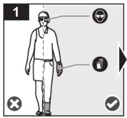
■ Use personal protective equipment. Always wear eye protection. Protective equipment such as a dust mask, non-skid safety shoes, hard hat, or hearing protection used for appropriate conditions will reduce personal injuries.
■ Prevent unintentional starting. Ensure the switch is in the off-position before connecting to power source and/or battery pack, picking up or carrying the tool. Carrying power tools with your finger on the switch or energising power tools that have the switch on invites accidents.
■ Remove any adjusting key or wrench before turning the power tool on. A wrench or a key left attached to a rotating part of the power tool may result in personal injury.
■ Do not overreach. Keep proper footing and balance at all times. This enables better control of the power tool in unexpected situations.
■ Dress properly. Do not wear loose clothing or jewellery. Keep your hair and clothing away from moving parts. Loose clothes, jewellery, or long hair can be caught in moving parts.
■ If devices are provided for the connection of dust extraction and collection facilities, ensure these are connected and properly used. Use of dust collection can reduce dust-related hazards.
■ Do not let familiarity gained from frequent use of tools allow you to become complacent and ignore tool safety principles. A careless action can cause severe injury within a fraction of a second.
POWER TOOL USE AND CARE
■ Do not force the power tool. Use the correct power tool for your application. The correct power tool will do the job better and safer at the rate for which it was designed.
■ Do not use the power tool if the switch does not turn it on and off. Any power tool that cannot be controlled with switch is dangerous and must be repaired.
■ Disconnect the plug from the power source and/or remove the battery pack, if detachable, from the power tool before making any adjustments, changing accessories, or storing power tools. Such preventive safety measures reduce the risk of starting the power tool accidentally.
■ Store idle power tools out of the reach of children and do not allow persons unfamiliar with the power tool or these instructions to operate the power tool. Power tools are dangerous in the hands of untrained users.
- Maintain power tools and accessories. Check for misalignment or binding of moving parts, breakage of parts and any other condition that may affect the power tool's operation. If damaged, have the power tool repaired before use. Many accidents are caused by poorly maintained power tools.
- Keep cutting tools sharp and clean. Properly maintained cutting tools with sharp cutting edges are less likely to bind and are easier to control.
■ Use the power tool, accessories and tool bits etc. in accordance with these instructions, taking into account the working conditions and the work to be performed. Use of the power tool for operations different from those intended could result in a hazardous situation. - Keep handles and grasping surfaces dry, clean and free from oil and grease. Slippery handles and grasping surfaces do not allow for safe handling and control of the tool in unexpected situations.
BATTERY TOOL USE AND CARE
■ Recharge only with the charger specified by the manufacturer. A charger that is suitable for one type of battery pack may create a risk of fire when used with another battery pack.
■ Use power tools only with specifically designated battery packs. Use of any other battery packs may create a risk of injury and fire.
- When battery pack is not in use, keep it away from other metal objects, like paper clips, coins, keys, nails, screws or other small metal objects, that can make a connection from one terminal to another. Shorting the battery terminals together may cause burns or a fire.
■ Under abusive conditions, liquid may be ejected from the battery; avoid contact. If contact accidentally occurs, flush with water. If liquid contacts eyes, additionally seek medical help. Liquid ejected from the battery may cause irritation or burns.
- Do not use a battery pack or tool that is damaged or modified. Damaged or modified batteries may exhibit unpredictable behaviour resulting in fire, explosion or risk of injury.
- Do not expose a battery pack or tool to fire or excessive temperature. Exposure to fire or temperature above 130°C may cause explosion.
- Follow all charging instructions and do not charge the battery pack or tool outside the temperature range specified in the instructions. Charging improperly or at temperatures outside the specified range may damage the battery and increase the risk of fire.
SERVICE
■ Have your power tool serviced by a qualified repair person using only identical replacement parts. This will ensure that the safety of the power tool is maintained.
■ Never service damaged battery packs. Service of battery packs should only be performed by the manufacturer or authorised service providers.
■ Always use safety protective devices. Do not use the product without the side discharge chute in place and working properly. The mulch cover should be correctly installed and working properly during mulching operation.
- Follow the manufacturer's instructions for proper operation and installation of accessories. Use only accessories approved by the manufacturer. The use of other accessories may increase the risk of injury.
■ Never interfere with the intended function of a safety device or reduce the protection provided by a safety device. Check the proper operation of the safety devices regularly.
■ Never use the product while people, especially children, or pets are within 15 m because of the danger of objects being thrown by contact with the blade.
■ Do not use the product when there is a risk of lightning. - Do not operate the product in poor lighting. The operator requires a clear view of the work area to identify potential hazards.
■ Be familiar with the controls and the correct use of the product.
■ Be aware of possible hazards when not using the product or when changing accessories. Following this rule reduces the risk of electric shock, fire, or serious personal injury.
■ Never carry passengers or children, even when the blades have stopped. They may fall off and be seriously injured or interfere with the safe operation of the product. Children who have been given rides in the past may suddenly appear in the mowing area for another ride and be run over or backed over by the product.
■ Never allow children or people with reduced physical, sensory, or mental capabilities, or persons who are unfamiliar with these instructions to operate, clean, or maintain the product. Local regulations may restrict the age of the operator. Children should be adequately supervised to ensure that they do not play with the product. - Keep in mind that the operator or user is responsible for accidents or hazards occurring to other people or their property.
- Keep hands and feet away from the cutting area, which is located under the mower deck and inside the side discharge chute. Keep clear of the side discharge chute opening at all times. Do not reach under the mower deck.
PREPARATION
■ Wear heavy, long trousers, long sleeves, and sturdy, anti-slip footwear. Do not wear short trousers, sandals, or go barefoot. Avoid wearing clothing that is loose-fitting or that has hanging cords or ties.
■ Always wear safety glasses with side shields. Use a face mask if operation is dusty.
- Objects struck by the blade can cause severe injuries to persons. Thoroughly inspect the area where the product is to be used, and remove all rocks, sticks, metal, wire, bones, toys, or other foreign objects. Remember, string or wire may entangle with the blades.
■ Before use, always visually inspect the product to ensure that blades, blade nuts, and the cutter assembly are not worn or damaged.
■ Never direct discharged material towards anyone. Plan the mowing pattern to avoid discharge of material towards bystanders, roads, sidewalks, windows, and cars. Avoid discharging material against a wall or obstruction, which may cause the material to ricochet back towards the operator.
OPERATION
- Operating a zero-turn mower is different from operating a standard riding mower. Zero-turn mowers are rear-wheel drive. The wheels operate independently based on the position of the joystick. Practice operating the product in a large, level, and open area using the driving instructions before mowing your grass. Once you can comfortably and reliably perform the manoeuvres, you are ready to mow your grass.
■ Before starting the product:
- Check the brake operation.
- Check the tyre pressure.
-
Check for loose fasteners.
-
Make sure that all guards are in place and working properly.
- Check the side discharge chute safety interlock system.
- Test the operator presence safety interlock system.
- Adjust the seat to the preferred position.
- Verify the battery charge level.
- Do not mow in reverse unless absolutely necessary. Before and while reversing, look behind and down for small children, bystanders, and pets.
■ Never leave a running product unattended. Always turn off the blades, engage the parking brake, stop the motor, and remove the start key before dismounting.
■ The product must be started with the user properly seated. Never start the product if:
• not all four wheels are on the ground
- the side discharge chute is exposed and is not protected by the mulch cover
- hands and feet of all persons are not clear of the cutting enclosure
■ Never use the product in a closed area.
■ Turn on the motor carefully according to instructions, and keep hands and feet away from blades. Do not put hands or feet near or under rotating parts.
- Stop the blade when crossing gravel surfaces to avoid discharging gravel and rocks. Drive the product slowly and carefully to avoid loss of control.
- Use extra care when approaching blind corners, shrubs, trees, or other objects including overhanging shrubs, which may block your view.
■ Slow down before turning.
- Watch for traffic when operating near roadways. Do not operate the mower on roadways.
-
Slopes are a major factor related to loss of control and tip-over accidents, which can result in severe injury or death. Operation on all slopes requires extra caution. If you cannot back up the slope or if you feel uneasy on it, do not mow it. Do not reverse down a slope. Never use the product on steep slopes greater than 12^ . Make a copy or cut out the slope guide at the back of this manual, and use it to determine if your slope is too steep for safe operation.
-
Mow up and down; not across the face of slopes.
- Avoid holes, ruts, bumps, rocks, property stakes, or other hidden objects. Uneven terrain could overturn the product. Tall grass can hide obstacles.
-
Use a slow speed so you will not have to stop suddenly or accidentally accelerate while on a slope.
-
Do not mow on wet grass when on a slope. Tyres may lose traction and you may lose control.
- Always keep the joystick in the forward position when going down slopes. Do not move to neutral and coast downhill, which may cause you to lose control of the mower. Always use the joystick and brake when traveling down the slope.
- Avoid starting, stopping, or turning on a slope. If the tyres lose traction, disengage the blades and proceed slowly straight down the slope.
- Keep all movement on slopes slow and gradual. Do not make sudden changes in speed or direction, which could cause the product to roll over.
- Use extra care while using the product with attachments; they can affect the stability of the product. Do not use the product on steep slopes greater than 12^ .
- Do not try to stabilise the product by putting your foot on the ground.
- Do not use the product near drop-offs, ditches, excessively steep slopes, or embankments. The product could suddenly roll over if a wheel goes over the edge or if the edges cave in and result in death or serious personal injury.
■ Operate the product only in temperatures between 0^ C and 40^ C.
CHARGER SAFETY WARNINGS
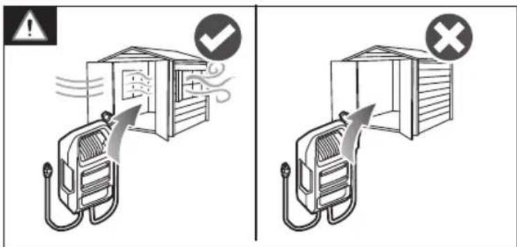
■ The charger is for indoor use only.
■ Do not recharge primary cells (non-rechargeable).
■ Before every use, examine the supply cord for damage. If there are signs of damage, it must be replaced by a qualified person at an authorised service centre to avoid a hazard.
- Charge the product indoors, in a well-ventilated area. Do not charge the product in a confined space.
The charger is equipped with a plug featuring a grounding pin and must be plugged into a matching outlet that has been properly installed and grounded in accordance with all local codes and ordinances. Do not use adaptors or modify the plug provided. If it does not fit the outlet, have the proper outlet installed by a qualified electrician.
ADDITIONAL BATTERY SAFETY WARNINGS
WARNING! Risk of fire, explosion, or burns. Do not disassemble, expose to heat above 60^ C, or incinerate the battery pack.
To reduce the risk of fire, personal injury, and product damage due to a short circuit, never immerse the product, battery pack, or charger in fluid or allow fluid to flow inside them. Corrosive or conductive fluids, such as seawater, certain industrial chemicals, and bleach or bleach-containing products, etc., can cause a short circuit.
■ Under extreme usage or temperature conditions, battery leakage may occur. If liquid comes in contact with the skin, wash immediately with soap and water, then neutralize with lemon juice or vinegar. If liquid gets into the eyes, flush them with clean water for at least 10 minutes, then seek immediate medical attention. Following this rule will reduce the risk of serious personal injury.
- Do not charge battery packs that show signs of leaks. Dispose of them properly.
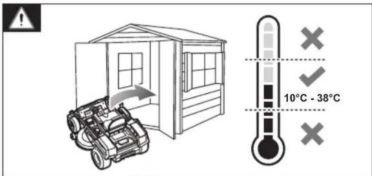
- Charge the battery pack in a location where the ambient temperature is between 10 °C and 38°C.
■ Store the battery pack in a location where the ambient temperature is between 0^ C and 20^ C.
■ Use the battery pack in a location where the ambient temperature is between 0^ C and 40^ C.
BATTERY PACK REMOVAL AND PREPARATION FOR RECYCLING
■ To preserve natural resources, recycle or dispose of batteries properly.
Upon removal, cover the battery pack terminals with heavy-duty adhesive tape. Do not attempt to destroy or disassemble the battery pack or remove any of its components. Lithium batteries must be recycled or disposed of properly. Never touch both terminals with metal objects and body parts as short circuit may result. Keep the battery pack away from children. Failure to comply with these warnings could result in fire and/or serious injury.
TRANSPORTATION AND STORAGE
■ Turn off the product, engage the parking brake, and remove the start key. Make sure that all moving parts have come to a complete stop. Allow the product to cool down before storing or transporting.
■ Remove all foreign materials from the product. Store the product in a cool, dry, and well-ventilated place that is inaccessible to children. The start key should be removed and stored in a separate location out of the reach of children.
- Keep the product away from corrosive agents, such as garden chemicals and de-icing salts. Do not store the product outdoors.
■ For transportation in vehicles, remove the start key, and secure the product against movement or falling to prevent injury to persons or damage to the product.
- Use extra care when loading or unloading the product into a trailer. Select low speed and carefully move the joystick as needed to control the speed. Always back onto the trailer when loading. When loading or unloading the product, do not exceed the maximum recommended operation angle of 12^ . Failure to follow these instructions can result in loss of control and result in death, serious personal injury, or property damage.
■ Use extreme caution when lifting or tilting the product for maintenance, cleaning, storage, or transportation. The blade is sharp. Keep all body parts away from the blade while it is exposed.
■ Store the product in a location where the ambient temperature is between -10^ and 50^ .
TRANSPORTING LITHIUM BATTERIES
■ Transport the battery in accordance with local and national provisions and regulations.
■ Follow all special requirements on packaging and labelling when transporting batteries by a third party. Ensure that no batteries can come in contact with other batteries or conductive materials while in transport by protecting exposed connectors with insulating, nonconductive caps or tape. Do not transport batteries
that are cracked or leaking. Check with the forwarding company for further advice.
TOWING SAFETY WARNINGS
■ Use common sense when towing equipment. Too heavy of a load while on a slope is dangerous. Tyres can lose traction with the ground and cause you to lose control of the product.
- Follow the manufacturer's recommendations for wheel weights or counterweights.
■ Total towed weight must not exceed the maximum towing load indicated in the product specifications section.
■ Attach tow equipment only at the hitch plate.
■ Never allow children or others on the towed equipment.
■ Stopping distance increases with speed and weight of load being towed. Travel slowly, and allow extra time and distance to stop.
- Do not turn sharply when towing. Use additional caution when turning or operating under adverse surface conditions. Use care when reversing.
MAINTENANCE
- Use only original manufacturer's replacement parts, accessories and attachments. Failure to do so can cause possible injury, can contribute to poor performance, and may void your warranty.
■ Service on the product and the charger must be performed by qualified repair personnel only. Service or maintenance performed by unqualified personnel could result in injury to user or damage to the product. Have the product serviced by an authorised service centre only. -
Maintain the product with care and in good working condition. Keep blades sharp and guards in place and in working order. To prevent serious personal injury, prevent damage to the product, and to maintain best performance, replace damaged, bent, cracked, or unevenly worn out blades. An unbalanced blade causes vibration that could damage the motor drive unit or could cause personal injury.
■ Turn off the product, engage the parking brake, and remove the start key. Make sure that all moving parts have come to a complete stop: -
before leaving the product unattended (including disposal of grass clippings)
- before clearing blockages or unclogging the discharge chute
• before checking, cleaning, or working on the product
• before removing the mulch cover
• before opening the grass discharge chute cover
• after striking a foreign object
– Thoroughly inspect the product for any damage.
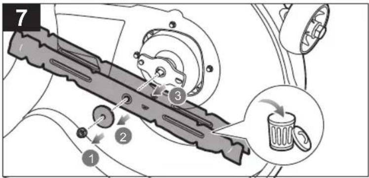
- Replace the blade if it is damaged in any way.
– Repair any damage before restarting and continuing to operate the product.
- whenever the product starts to vibrate abnormally (check immediately)
- Inspect for damage, particularly the blades.
- Replace the blade if it is damaged in any way.
– Replace or repair any damaged parts.
– Check for and tighten any loose parts.
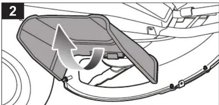
■ The side discharge chute is a spring-loaded guard that covers the side discharge opening on the cutting deck and deflects grass clippings and debris away from the operator. Always ensure that the motor is off and the blades have stopped moving before inspecting, moving, cleaning, or performing maintenance on the side discharge chute.
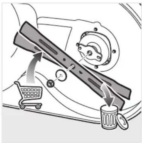
- Replace damaged blades and bolts in sets to preserve balance.
■ Remove the start key from the product before storing, servicing, or changing accessories. Such preventive safety measures reduce the risk of starting the product accidentally.
- You may make adjustments and repairs described in this manual. For other repairs, have the product serviced by an authorised service centre only.
■ Contact an authorised service centre to replace damaged or unreadable labels.
- Check all nuts, bolts, and screws at frequent intervals for proper tightness to ensure that the product is in safe working condition.
■ The blade bolts must be tightened to the recommended torque.
- Check the brakes before each use and frequently during use. Adjust and service the brakes as required.
- Be careful during adjustment of the product to prevent entrapment of the fingers between moving blades and fixed parts of the product.
The cutting blades continue to rotate for a few seconds after the motor is turned off. When servicing the blades, be aware that even though the power source is switched off, the blades can still be moved. Never place any part of the body in the blade area until you are sure the blades have stopped rotating.
The blade on the product is sharp. Use extreme caution and wear heavy-duty gloves when fitting, replacing, cleaning or checking bolt security.
■ After each use, clean the plastic parts with a soft, dry cloth. Any part that is damaged should be properly repaired or replaced by an authorised service centre.
- Keep the product free of grass, leaves, or other debris build up.
- Do not use water to clean the product. Use an air moving device, such as a compressor or leaf blower to clean the product.
TYRE MAINTENANCE
The product is equipped with tubeless tyres. When tyres are worn, the traction of the mower decreases, which increases the chance of having an accident. Replace the tyres when the depth on the tread is 4 mm or less, or any time there is damage to the tyre. Always use original replacement tyres. Using incorrect tyres on the product could cause loss of control, which could cause serious personal injury.
Have the tyres replaced only by an authorised service centre.
TYRE AIR PRESSURE
Check the air pressure in all four tyres before each use. Improper air pressure aff ects handling, steering response, traction, tyre life, level cutting, and operator comfort. Make sure that tyres are infl ated to the recommended air pressure. The tyre air pressure should only be measured or adjusted when tyres are cold.
TYRE REPAIR
If a leak or flat tyre occurs due to a puncture, the tyre may be repaired using a plug-type patch. If the damage is from a cut, or if the puncture cannot be repaired using a plug, replace the tyre.
BRAKE ADJUSTMENT
See page 164.
Ensure that the brakes are properly functioning before each use and frequently during use. Improper brake function can cause loss of control in an emergency situation and result in death or serious personal injury.
If the mower travels further before stopping when stepping on the brake pedal, the brakes need adjusting.
After final adjustment, test the brakes by driving the mower at normal speed on fl at ground to be sure that the mower stops quickly when the brake pedal is stepped on.
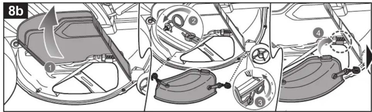
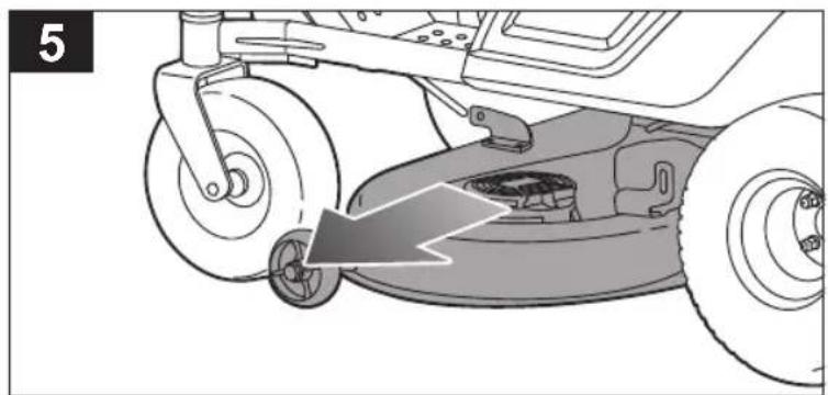
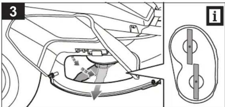
REMOVING THE CUTTING DECK
The cutting deck lift is spring-assisted and under tension. Serious personal injury can occur if the spring-assisted deck lift is released suddenly. Always use the auto stop plug to secure the deck height adjustment lever in place while removing or installing the deck. Keep hands and fingers below and away from deck lift at all times.
CLEARING BLOCKAGES
■ Turn off the product, engage the parking brake, and remove the start key. Set the cutting deck to the maximum height. Make sure that all moving parts have come to a complete stop.
■ Always wear heavy-duty gloves when checking or clearing a blockage. The blades are sharp and the blockage itself could be a sharp object.
- Check and carefully clear the side discharge chute for blockages. Remember that the blade may move during cleaning.
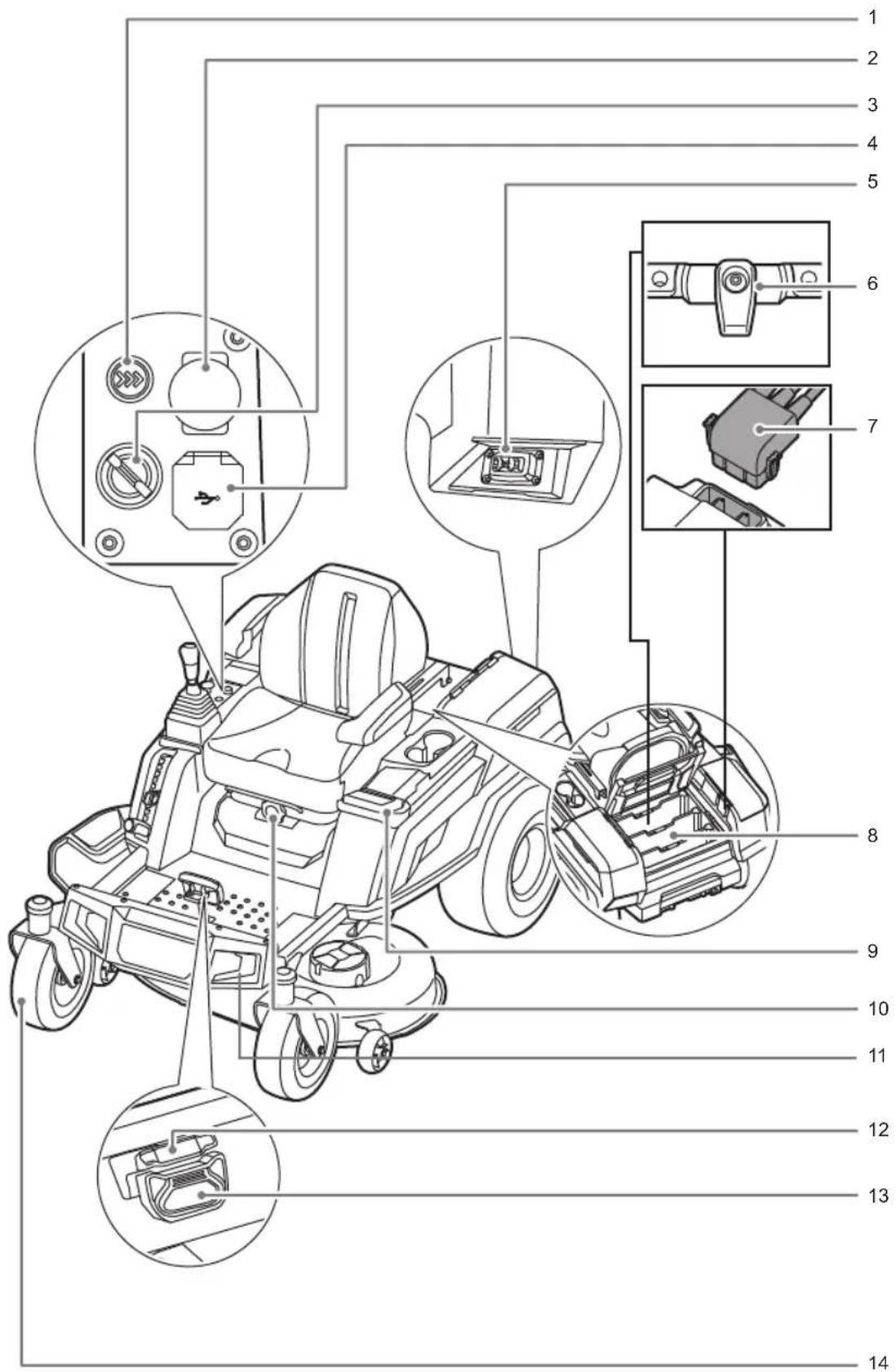
KNOW YOUR PRODUCT
See pages 146-147.
1. Grass catcher boost button
The grass catcher boost button works with the grass catcher accessory. This button will engage a fan to help push grass clippings through the catcher tube.
2. Blade engage knob
The blade engage knob activates or stops the cutting blades.
- Pull up the blade engage knob to activate the blades.
- Press the blade engage knob to stop the blades.
NOTE: The blades should stop within 5 seconds. If the blades do not stop, contact an authorised service centre.
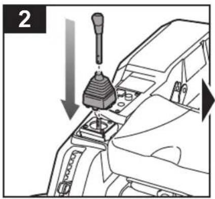
3. Power switch with start key
The power switch turns the product on and off. The start key must be inserted before the switch can be operated. When the key is in the on position, the power switch is also used to power optional manufacturer-approved mower accessories.
4. USB port
The USB charging port provides charging power of 5 V dc at up to 2 A for your cell phone, MP3 player, or other USB devices. Check the manual of your device for specific charging requirements.
Connect one end of a USB cable (not provided) to your device and the other end to the USB charging port on the product to charge your device.
NOTE: The USB port is powered only when the start key is in the ON position.
⚠ WARNING! Attempting to charge devices rated more than 1 A could damage the USB charging port and the mower. Always close the USB cover when not in use to prevent trapping debris in the port.
⚠ WARNING! Never use headphones or any electronic device, such as a smartphone or tablet, while operating the product. A lapse in concentration while operating the product may result in serious personal injury to the operator or a bystander.
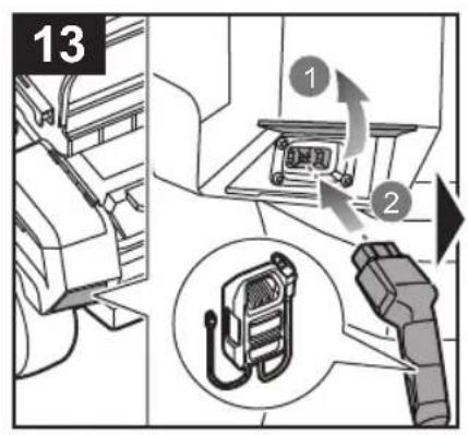
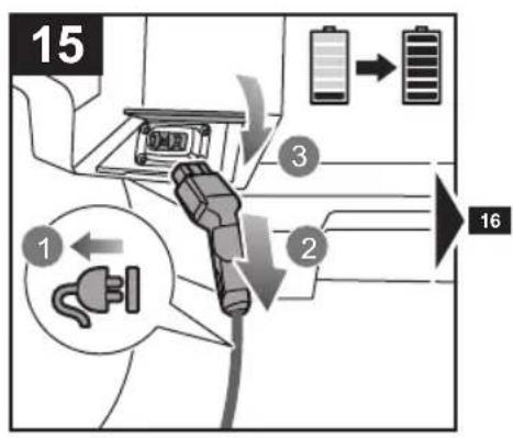
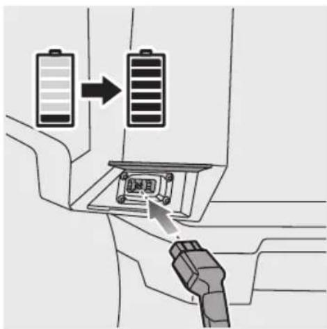
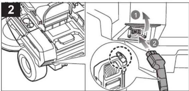
5. Charging port
The charging port connects the charger to recharge the 72 V battery packs in series followed by any 36 V battery pack if installed. 36 V battery packs can only be charged when 72 V battery packs are installed.
6. Battery latch
7. Quick-connect plug
8. Primary battery port
The primary battery port can store up to three 72 V battery packs.
9. LCD screen
The LCD screen monitors and activates the features on the product. Refer to the LCD user guide.
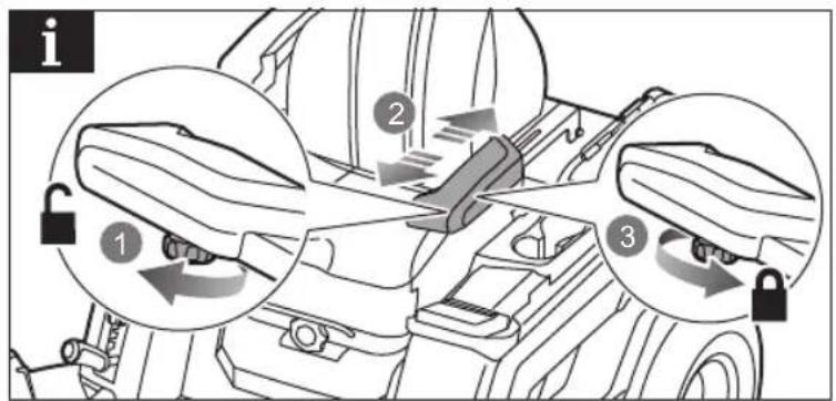
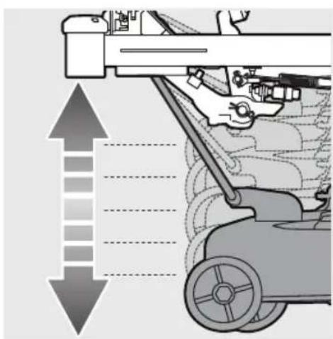
10. Seat suspension knob
The seat suspension knob adjusts the softness or firmness of the seat suspension.
11. Headlights
The front LED headlights can be controlled from the LCD interface.
12. Parking brake
The parking brake locks the product in the brake position.
13. Brake pedal
The brake pedal slows down and stops the product.
14. Front tyre
The front tyres rotate 360 degrees for manoeuverability.
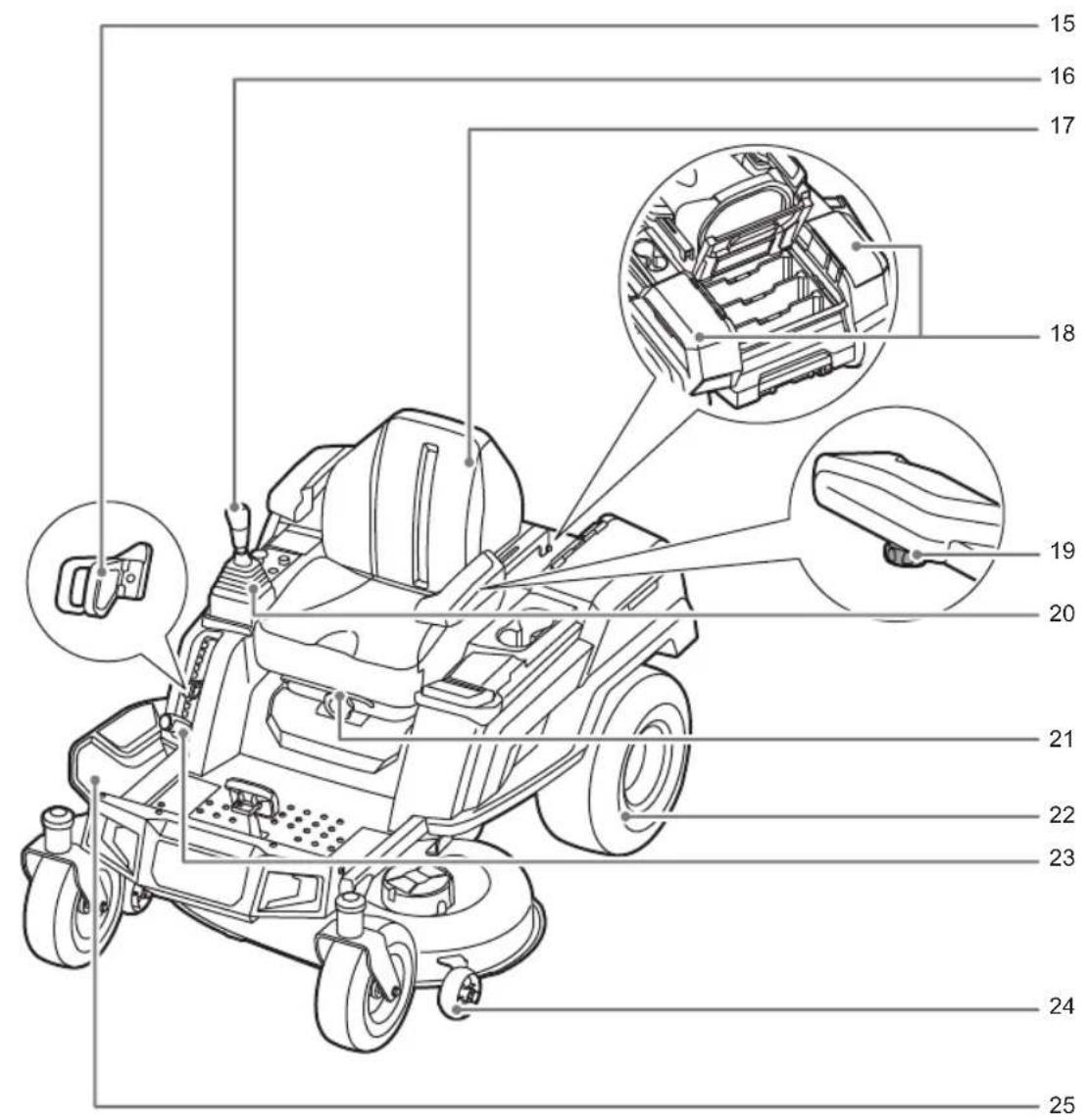
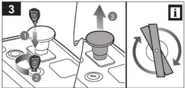
15. Auto-stop plug
Once the preferred cutting height is determined for your lawn, install the auto-stop plug just below the lever position to easily return to the preferred height.
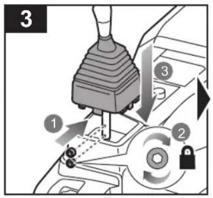
16. Intelligent drive system joystick
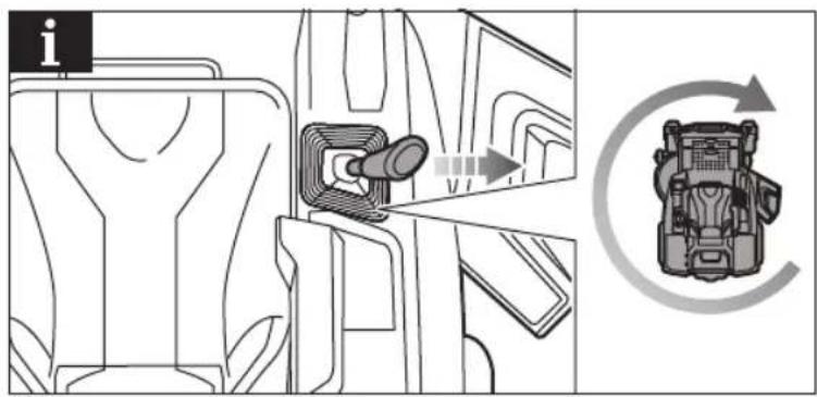
The intelligent drive system joystick automatically returns to the neutral position for safety. The joystick easily allows the user to operate the product with only one hand. The software is designed to correct gradual wheel turns to help eliminate divots in the lawn.
17. Seat (with operator presence safety interlock system)
The seat has an interlock system that stops the blades if the operator leaves while the mower is running.
Test the system before each use to ensure that it is working correctly.
-
Stop the product on a level surface, and engage the parking brake.
-
Set the joystick in the neutral position.
-
Insert the start key, and turn the key to the ON position.
-
Pull up the blade engage knob to activate the blades.
- Briefly stand up but do not get off the mower.
The blades should stop within 5 seconds. If the blades do not stop, contact an authorised service centre. Do not operate the mower until the safety interlock system has been repaired.
18. Storage / 36 V battery pack port
The product does not operate on only 36 V battery packs. At least one 72 V battery pack should be installed to run the drive and blade motors.
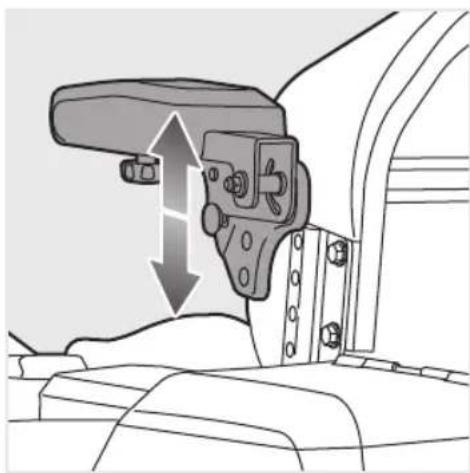
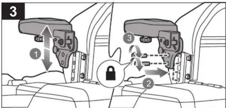
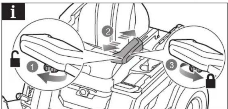
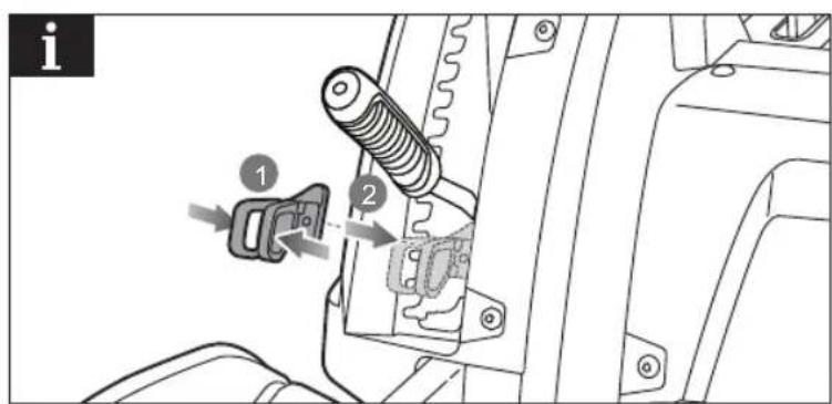
19. Armrest knob
The armrest knob secures the armrest into place.
20. Dust cover
21. Seat adjustment bar
22. Rear tyre
23. Deck height adjustment lever
The deck height adjustment lever raises or lowers the cutting deck.
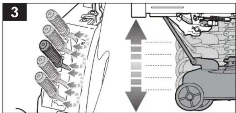
24. Deck wheels
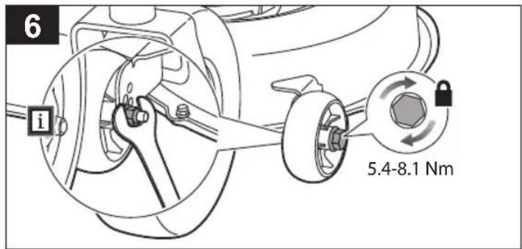
To prevent scalping the lawn when encountering high spots, the cutting deck wheels should be positioned approximately 1.27 cm (1/2 in.) off the ground.
25. Side discharge chute with safety interlock system
The side discharge chute deflects grass clippings. Before using the product, check that the side discharge chute is properly closed. It has an interlock system that stops the blades if the chute is opened during operation. Stop using the product and have it serviced by an authorised service centre if the blades do not stop when the side discharge chute is lifted during use by an obstacle.
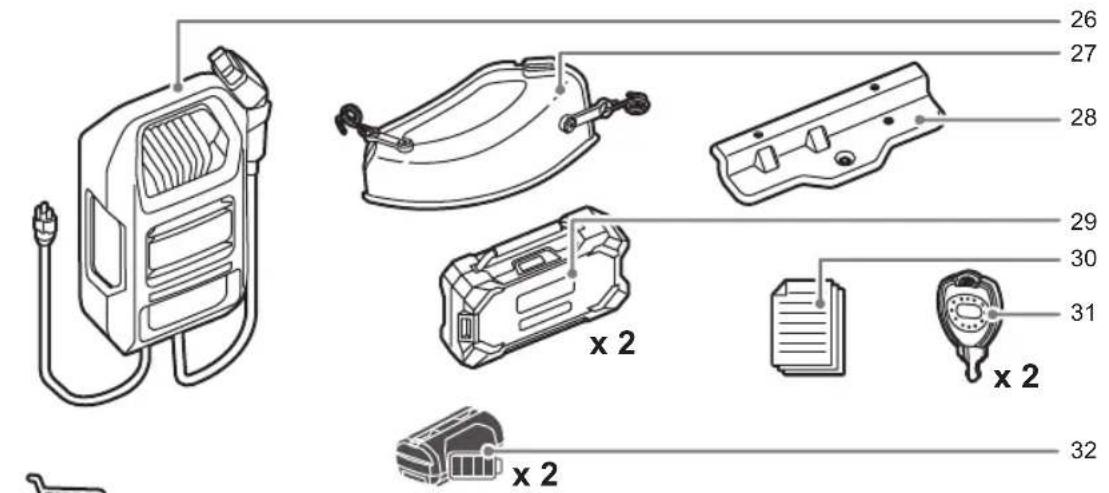
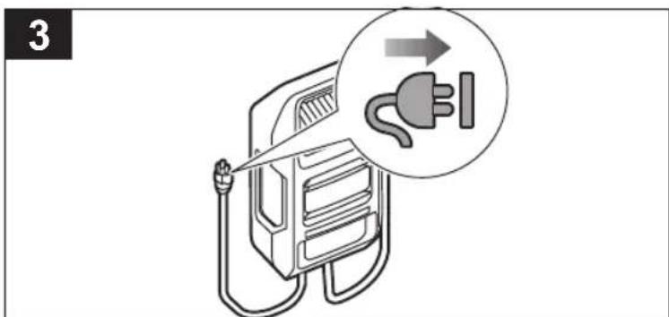
26. Charger (72 V)
The charger recharges the batteries of the mower.
27. Mulch cover
The mulch cover covers the side discharge chute, which allows the mower blade to cut and recut for finer clippings.
28. Hitch plate
29. Battery pack (72 V)
72 V battery packs must be used to power the product.
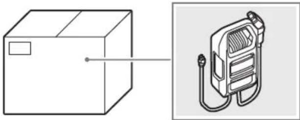
30. Operator's manual
The operator's manual provides important safety warnings and instructions on how to properly and safely operate and maintain the product.
31. Start key
The start key turns the power switch to the on or off position.
32. Battery pack (36 V)
SYMBOLS ON THE PRODUCT

Safety alert

Read and understand all instructions before operating the product. Follow all warnings and safety instructions.

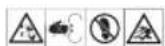
Wear eye protection.

Beware of thrown or flying objects.

Keep all bystanders, especially children and pets, at least 30 m away from the operating area.
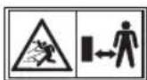
Beware of thrown or flying objects. Keep all bystanders, especially children and pets, at least 30 m away from the operating area.
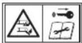
Keep hands and feet away from the blades. Turn off the product and remove the start key before maintenance.

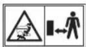
Never carry children or anyone, even when the blades are off.

Always look down and behind you before and during backing and make sure children, bystanders, and pets are clear of the area.

Do not operate the product on inclines greater than 12^ . Mow up and down slopes, not across.

Stay at least two moving widths (2.2 m) away from any ditches, drop-off s, or water. Front caster wheels can rotate when the mower is stopped, even with the brake applied, and can cause mower to go over the edge or into the water.

Keep hands and feet away from rotating blades.


Do not charge the battery or expose the product to rain or damp conditions.
Guaranteed sound power level
Keep hands and feet away from blade and cutting area. Do not step on the cutting deck or on the side discharge chute.

Keep all bystanders, especially children and pets, at least 30 m away from the operating area.

Never carry children or anyone, even when the blades are off.
Always look down and behind you before and during reversing, and make sure that children, bystanders, and pets are clear of the area.
Keep hands and feet away from the blade and cutting area.

Keep hands and fingers clear of pinch points.

Charging port

European Conformity Mark

EurAsian Conformity Mark

Ukraine Conformity Mark

British Conformity Mark

Do not dispose of waste batteries, waste electrical and electronic equipment as unsorted municipal waste. Waste batteries and waste electrical and electronic equipment must be collected separately. Waste batteries, waste accumulators, and light sources have to be removed from the equipment. Check with your local authority or retailer for recycling advice and collection point. According to local regulations, retailers may have an obligation to take back waste batteries and waste electrical and electronic equipment free of charge. Your contribution to the reuse and recycling of waste batteries and waste electrical and electronic equipment helps to reduce the demand of raw materials. Waste batteries, in particular containing lithium, and waste electrical and electronic equipment contain valuable and recyclable materials, which can adversely impact the environment and the human health if not disposed of in an environmentally compatible manner. Delete personal data from waste equipment, if any.

Electric shock hazard

Step on the brake pedal to stop the product.
Push the top part of the pedal to engage the parking brake.
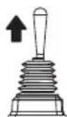
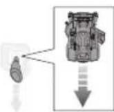
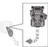
Pull up the joystick to activate the drive system.
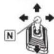
The joystick is in neutral position. Push or pull the joystick to move the product.
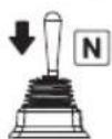
Push down the joystick to lock and set it in the neutral position.

When the joystick is pushed down, the product will beep twice to indicate that the joystick has returned to the neutral position.
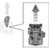
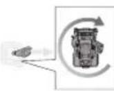
Push the joystick forwards to move the product forward.
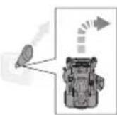
Push the joystick backwards to move the product backward.
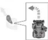
Push the joystick diagonally to the forward left position to make a forward left turn.
Push the joystick diagonally to the forward right position to make a forward right turn.
Pull the joystick diagonally to the backward left position to make a reverse right turn.
Pull the joystick diagonally to the backward right position to make a reverse left turn.
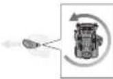
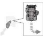
Push the joystick to the left to perform a left zero-turn.
Push the joystick to the right to perform a right zero-turn.
SYMBOLS IN THIS MANUAL

Parts or accessories sold separately

Note

Warning
UNPACKING
See pages 144-145.
■ Remove and set aside all accessible packaging and wrap from the unit and parts. Do not discard the packing material until you have carefully inspected and satisfactorily operated the product.
■ Inspect the product carefully to ensure that no breakage or damage occurred during shipping.
If any parts are damaged or missing, contact an authorised service centre. Do not assemble the product until the parts are replaced with new original manufacturer's parts. Assembling the product with damaged, missing, or incorrect parts could result in serious personal injury.
If any parts are already assembled to the product when you unpack it, verify that the part is assembled correctly, is properly tightened, and is torqued correctly (where applicable) before proceeding to the next assembly step. The use of a product that may have been improperly assembled could result in serious personal injury.
ASSEMBLY
See pages 148-150.
The product should be assembled while positioned on the bottom frame. When assembly is complete, set the cutting deck to its maximum height, then position a ramp next to the frame bottom, and slowly and carefully drive the product off the frame.
■ Strictly adhere to all torque wrench tightening specifications. Failure to do so could cause serious personal injury.
■ To prevent accidental starting that could cause serious personal injury, always remove the start key from the product when assembling the parts.
Use extra care when driving the product off of the frame. Press the low speed drive button and carefully move the joystick and/or press the brake pedal as needed to control the speed. When driving the product off of the frame, do not exceed the maximum recommended operation angle of 12^ . Failure to follow these instructions can result in loss of control and result in death, serious personal injury, or property damage.
If no ramp is available, slowly and carefully drive the product off the frame in reverse while looking down and behind. Driving the product off the frame in the forward direction without a ramp can cause damage to the cutting deck.
CHARGER LED INDICATOR
| Charger status | Battery pack inserted | Battery pack | Red LED | Green LED | Orange LED | Action |
| Power on | No | - | On | Off | Off | The charger is connected to the power supply. Connect to a battery pack or product to begin charging. |
| Testing Yes | Hot Off | O | ff | On | The charger begins charging once the battery pack cools down. | |
| Cold Off | O | ff | The charger begins charging once the battery pack warms up. | |||
| Error Yes - Flash | Flash Off | If the status does not change after removing and reconnecting the charger, charge a different battery pack or product.If a different battery pack or product charges normally, contact an authorised service centre.If a different battery pack or product still shows an error status, replace the charger. | ||||
| Charging | Yes | - | Off | Flash | Off | The battery pack or product is charging. |
| Ready | Yes | - | Off | On | Off | Charging is complete. The LED indicator will turn off after 10 minutes. |
MAINTENANCE SCHEDULE
| Inspect before each use | Every 25 hours | Every 50 hours or yearly | Before storage | Once a month during storage | |
| Check the brake operation. | x | ||||
| Check the tyre pressure. | x | ||||
| Check the side discharge chute and operator presence safety interlock systems. | x | ||||
| Check for loose fasteners. | x | x | |||
| Remove all foreign materials from the product. | x | x | |||
| Check / Replace the blades. | x | x | |||
| Clean the battery terminals. | x | ||||
| Check and charge the battery. | x | x |
NOTE: Maintenance should be performed more frequently when the product is used in dusty areas.
When the product has exceeded the maximum figures specified in the table, maintenance should still be cycled according to the intervals of time or hours stated herein.
If you are unsure how to perform any of the maintenance items listed above, have the product serviced by an authorised service centre only.
TROUBLESHOOTING
If these solutions do not solve the problem, contact an authorised service centre.
Problem Possible cause Solution
| The product does not start. | The battery charge is low. Charge the battery. | |
| The charger is connected to the product. Disconnect the charger from product. | ||
| The start key is not installed or is in the OFF position. | Insert the start key, and turn it to the ON position. | |
| Poor battery cable connections Check and clean all the battery connections. | ||
| The product does not move. | The start key is not installed or is in the OFF position. | Insert the start key, and turn to the ON position. |
| The joystick is not pulled up. Pull up the joystick. | ||
| The joystick is in the neutral position. Move the joystick in the preferred direction (forward or reverse). | ||
| The brake is pressed and/or parking brake is engaged. | Release the brake pedal and the parking brake, then set the joystick in the neutral position to reset the mower. | |
| The charger is connected to the product. Disconnect the charger from product. | ||
| The operator is not fully seated. Fully sit down on the seat, return the joystick to the neutral position, and try again. | ||
| The product is cutting grass unevenly. | The tyre pressure is uneven. Check the tyre pressure in all four tyres. | |
| The mower deck is not level. Perform cutting deck level adjustment. | ||
| The blade is worn, bent, loose, or dull. Replace the blade. | ||
| There is build-up of debris under the product. Clean underside of the mower deck. | ||
| The mowing speed is too fast. Mow at a slower speed. | ||
| The product is not mulching properly. | There are wet grass clippings sticking to the underside of the deck. | Wait until the grass dries before mowing. |
| The grass is too high. Mow once at a high cutting height, then mow again at the preferred height. | ||
| The blade is worn, bent, loose, or dull. Replace the blade. | ||
| The mowing speed is too fast. Mow at a slower speed. | ||
| The product is vibrating at a higher speed. | The blade is unbalanced, loose, or excessively or unevenly worn. | Replace the blade. |
| The motor shaft is bent. | Turn off the product, and remove the start key. Inspect the product for damage. Have the product serviced by an authorised service centre before restarting. | |
| Poor grass discharge. | The side discharge chute or opening is plugged. | Clean the side discharge chute and opening. |
| The grass is wet. Allow grass to dry before mowing. | ||
| The mowing speed is too fast. Mow at a slower speed. | ||
| The grass is too high. Mow once at a high cutting height, then mow again at the desired height. | ||
| The motor stops while cutting. | The cutting height is set too low. Raise the cutting height. | |
| The battery charge is low. Charge the battery. | ||
| The blades do not rotate. | The battery charge is low. Charge the battery. | |
| The side discharge interlock switch is not pressed by the side discharge chute. | Push down the side discharge chute, and make sure that it fully presses the side discharge interlock switch. | |
| The blade engage knob is down. Pull up the blade engage knob to activate the blades. | ||
| The operator is not fully seated. Fully sit down on the seat. | ||
| There is build-up of debris under the mower. Clean the underside of the mower deck. | ||
| The blades do not rotate while moving in reverse. | The blade engage knob is down. Pull up the blade engage knob to activate the blades. | |
| The product won't reach full speed. | The battery charge is low. Charge the battery. | |
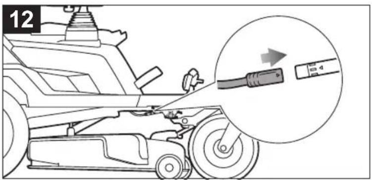
| The blades continue to turn after the operator leaves the seat without engaging the parking brake. | The safety interlock system is not functioning correctly. | Ensure that the safety interlock system seat plug is fully connected. If the blades still won't stop, have the product serviced by an authorised service centre only. |
| The headlights are not working. | The headlights are off. | Press the headlight button to turn on the headlights. |
| The headlights are damaged. Replace the headlights. | ||
| The battery does not charge. | The battery cells are bad. Replace the battery. | |
| The cable connections are poor. Check and clean all the battery connections. | ||
FREQUENTLY ASKED QUESTIONS
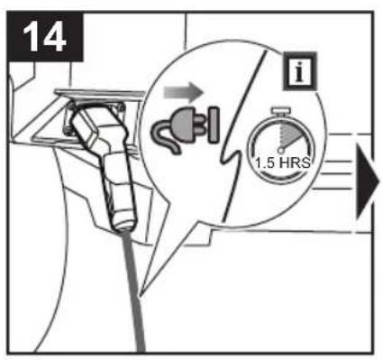
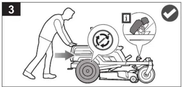
- Should the mower remain plugged into the charger when not in use?
- Yes, continually charge the mower when not in use.
■ What can cause the blades to stop during use?
- Check the battery level. The deck motor turns off when the battery power gets low to allow you enough time to drive back to the charging location. Drive back and charge the battery immediately.
- If the battery level is not low, slow down or raise the cutting deck to a higher level. High load applications can also cause one or both deck motors to stop.
- Check that the side discharge chute is properly closed. Push down the side discharge chute, and make sure that it fully presses the side discharge interlock switch.
■ When coasting downhill, why does the mower sometimes accelerate and sometimes does not?
- For your safety and better performance, the mower is designed to automatically limit its speed when travelling on a slope, which may cause fluctuations in speed.
■ When operating the mower, how do I bring the mower to a complete stop?
- To stop the mower, step on the brake pedal in front of the operator. This product is not a hydrostatic drive.
■ Why does the mower make a beeping sound when I leave the seat?
- The parking brake has not been engaged or the start key is still installed and in the ON position. Always remove the key when the mower is not in use.
■ When should I use the parking brake?
- Always engage the parking brake before getting off the mower.
■ Can I rinse off the mower deck with a garden hose?
- Do not clean the product with water. Use a blower or air compressor to clean it.
SYMBOLES APPLIQUÉS SUR LE PRODUIT

Alerte de sécurité

MACHEN SIE SICH MIT IHREM PRODUKT VERTRAUT
SYMBOLE AUF DEM PRODUKT

Sicherheitswarnung

VEILIGHEIDSWAARSCHUWINGEN VOOR OPLADER
VEILIGHEIDSWAARSCHUWINGEN VOOR HET SLEPEN
SYMBOLER PÅ PRODUKTET

Sikkerheds Varsel

OFTE STILLEDE SP∅RGSMÅL
TRANSPORT OCH FÖRVARING
SYMBOLER PÅ PRODUKTEN

Säkerhetsvarning
för

KJENN PRODUKTET DITT
Se side 146-147.
1. Gressfangerboostknapp
SYMBOLER PÅ PRODUKTET

Sikkerhetsalarm

OFTE STILTE SP∅RSMÅL
natural_image
Technical line drawing of a mobile vehicle chassis with internal components and external housing (no text or symbols)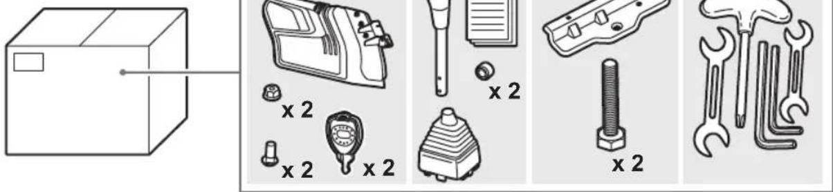
natural_image
Technical line drawing of a box and a gas pump device (no text or symbols)
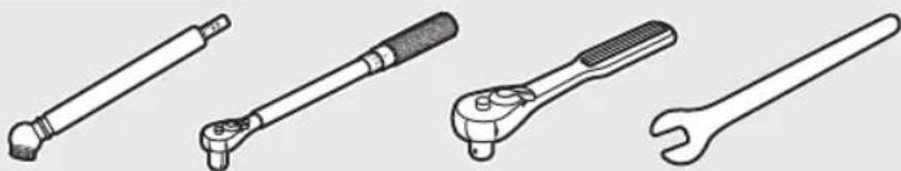
12 mm/13 mm

6 mm

natural_image
Line drawings of four different wrenches (tension, adjustable wrench, wrench, and wrench) shown in line style without any text or symbols.RY72ZTRX107


natural_image
Technical diagram of a mechanical component with a downward arrow indicating a feature (no text or symbols present)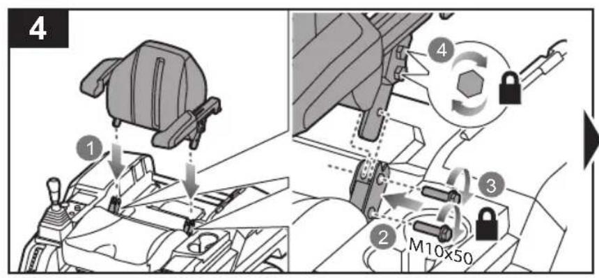
9
natural_image
Technical diagram of a vehicle engine compartment showing internal components and airflow direction (no text or labels)
13
natural_image
Mechanical assembly diagram showing a wheel and shaft assembly (no text or symbols)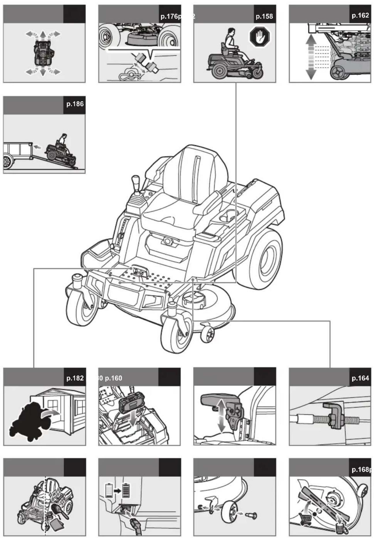
natural_image
Top-down diagram of a vehicle with directional arrows indicating flow or movement (no text or symbols)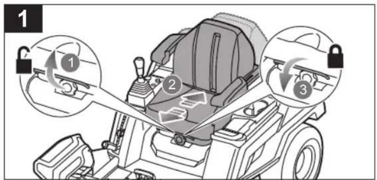
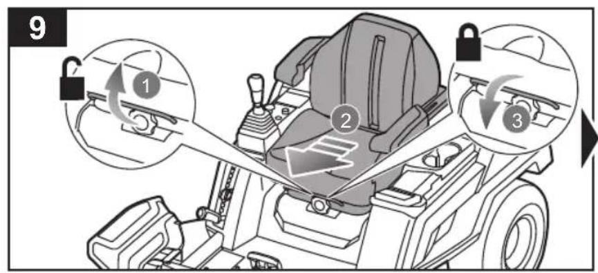
EN ■ Ensure that the seat is locked into place before operating the mower. A seat that is not secure can cause the operator to shift and lose control of the mower.
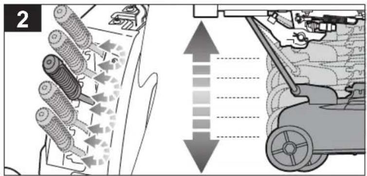
■ Before driving to the mowing area or over gravel surfaces, turn off the blades and set the cutting deck to the maximum height.
EN ■ Pull up the joystick to activate the drive system. Push the joystick forwards to drive the product forward in a straight line. The farther forwards the joystick is pushed, the faster the product will move. To slow down, slowly pull the joystick back towards the centre position. To stop, move the joystick back into the centre, neutral position.
Pull the joystick backwards to drive the product in reverse in a straight line. The farther backwards the joystick is pulled, the faster the product will move. To slow down, slowly push the joystick back towards the centre position. To stop, move the joystick back into the center, neutral position.
■ To make turns, push the joystick in the preferred turn direction. When driving forward or reverse, the angle of the joystick controls the direction of the turn.
To make zero turns, slow down but make sure that the rear wheels are still in motion. Then, move the joystick directly to right or left of the centre position. Moving the joystick right or left determines the direction of rotation of the turn.
NOTE: Perform zero turns at a slow speed to help prevent damage to your lawn.
natural_image
Diagram showing a camera inside a vehicle's seat with a circular arrow indicating rotational motion (no text or symbols)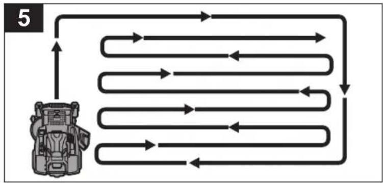
flowchart
graph TD
    A["Device"] --> B{Loop 1}
    B --> C["Loop 2"]
    C --> D{Loop 3}
    D --> E["Loop 4"]
    E --> F{Loop 5}
    F --> G["Loop 6"]
    G --> H{Loop 7}
    H --> I["Loop 8"]
    I --> J{Loop 9}
    J --> K["Loop 10"]
    K --> L["Loop 11"]
    L --> M["Loop 12"]
    M --> N["Loop 13"]
    N --> O["Loop 14"]
    O --> P["Loop 15"]
    P --> Q["Loop 16"]
    Q --> R["Loop 17"]
    R --> S["Loop 18"]
    S --> T["Loop 19"]
    T --> U["Loop 20"]
    U --> V["Loop 21"]
    V --> W["Loop 22"]
    W --> X["Loop 23"]
    X --> Y["Loop 24"]
    Y --> Z["Loop 25"]
    Z --> A
PT
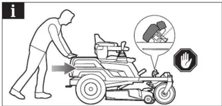
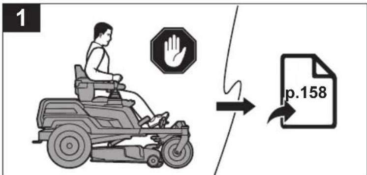
natural_image
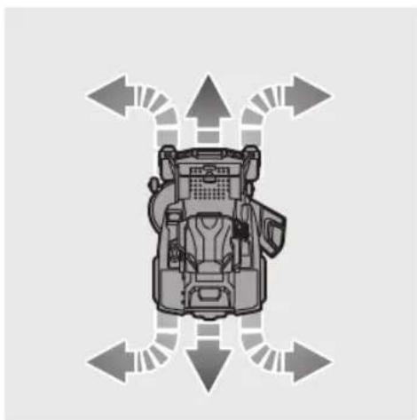
Illustration of a person using an electric mobility vehicle with a hand symbol (no text or labels)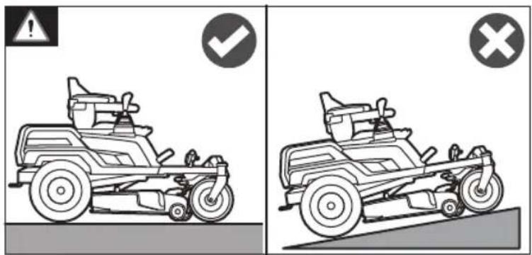
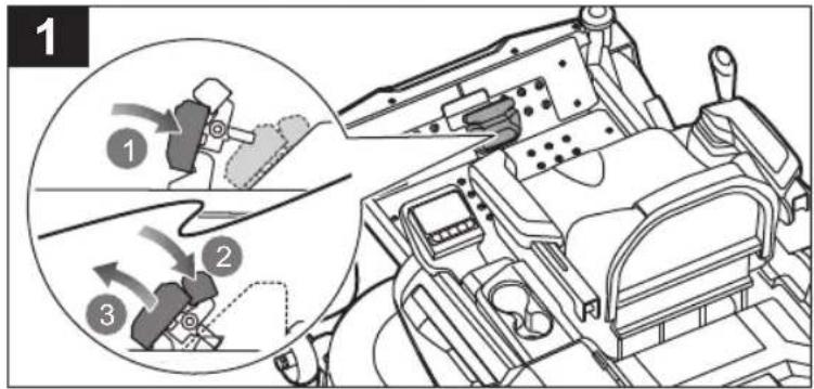
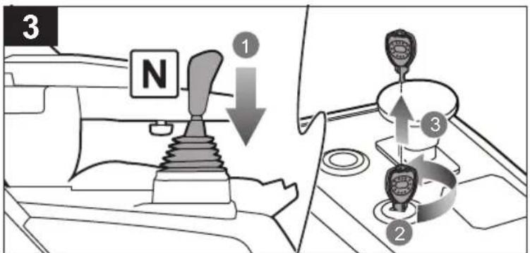
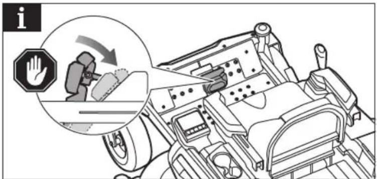
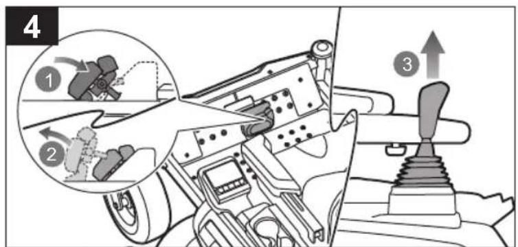
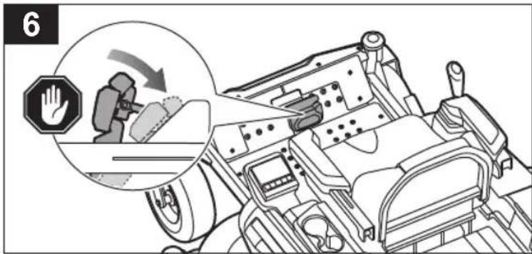
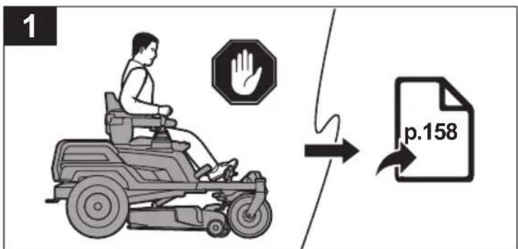
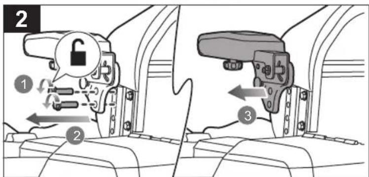
| EN | ■ Always engage the parking brake, turn off the blades, set the joystick to the neutral position (centered) and push it down. Turn off the product, and remove the start key before dismounting from the product. The product emits a beeping sound if the parking brake is not engaged and the start key is left on the power switch. |
| FR | ■ Engagez toujours le frein de stationnement, éteignez les lames, mettez la manette au point mort (centrée) et poussez-la vers le bas. Éteignez le produit et retirez la clé de contact avant de démonter le produit. Le produit émet un signal sonore si le frein de stationnement n'est pas enclenché et si la clé de contact est restée sur l'interrupteur d'alimentation. |
| DE | ■ Nutzen Sie immer die Feststellbremse, schalten Sie die Messer aus, schieben Sie den Joystick in die Neutralstellung (mittig) und schieben Sie ihn dann nach unten. Schalten Sie das Gerät aus und entfernen Sie den Startschlüssel, bevor Sie absteigen. Das Gerät gibt einen Warnton ab, wenn die Feststellbremse nicht angezogen ist und sich der Startschlüssel noch im Zündschloss befindet. |
| ES | ■ Active siempre el freno de estacionamiento, detenga el funcionamiento de las cuchillas, coloque la palanca de mando en la posición neutra (posición central) y presiónela hacia abajo. Apague el producto y retire la llave de arranque antes de bajarse del producto. El producto emite un pitido si el freno de estacionamiento no se ha accionado y se deja la llave de arranque en el conmutador de arranque. |
| IT | ■ Inserire sempre il freno di stazionamento, disattivare le lame, impostare il joystick in posizione folle (centro) e spingerlo verso il basso. Spegnere il prodotto e rimuovere il tasto start prima di smontare il prodotto. Il prodotto emette un suono di beep se il freno di stazionamento non è inserito e la chiave start viene lasciata sull'interruttore power. |
| NL | ■ Gebruik allijd de parkeerrem, zet de messen stil, zet de joystick in de neutrale stand (in het midden) en duw deze omlaag. Schakel het product uit, en verwijder de startsleutel voordat u van het product afstapt. De machine laat een piepend geluid horen als de parkeerrem niet is ingeschakeld en de startsleutel op de aan/uit-schakelaar is blijven staan. |
| PT | ■ Engrene sempre o travão de estacionamento, desligue as lâminas, coloque o joystick na posição de ponto morto (ao centro) e empurre para baixo. Desligue o produto e retire a chave da ignição antes de sair do produto. O produto emite um som intermitente se o travão de estacionamento não for engrenado e a chave de ignição permanecer no interruptor geral. |
| DA | ■ Aktiver alltid parkeringsbremsen, sluk for klingerne, placer joysticket i den neutrale position (centreret), og skub det ned. Sluk for produktet, og fjern startnøglen inden du går ned af produktet. Produktet udsender en biplyd, hvis parkeringsbremsen ikke er aktiveret, og startnøglen er efterladt i afbryderen. |
| SV | ■ Slå alltid på parkeringsbromsen, stäng av bladen, ställ styrspaken i friläget (mittläget) och tryck ner den. Stäng av produkten och ta ur startnyckeln innan du stiger av från produkten. Produkten avger ett pipande ljud om parkeringsbromsen inte är påslagen och startnyckeln sitter kvar i strömbrytaren. |
| FI | ■ Kytke käsijarru pälle alna, sammuta terät, aseta joystick vapaa-asentoon (keskelle) ja paina se alas. Sammuta tuote ja irrota virta-avain ennen tuotteen pältä nousemista. Laite antaa äänimerkin, jos käsijarru ei ole kytkettynä ja virta-avain jätetty virtakytkimeen. |
| NO | ■ Sett alltid på håndbremsen, slå av bladene, sett joysticken i nøytral posisjon (sentrert) og skyv den ned. Slå av produktet og fjern startnøkkelen för demontering fra produktet. Produktet avgir en pipelyd hvis parkeringsbremsen ikke er satt på og startnøkkelen blir värende på strömbryteren. |
natural_image
Mechanical assembly diagram showing a lever mechanism with a downward arrow indicating motion (no text or symbols present)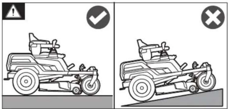


natural_image
Diagram of a mechanical device with directional arrows indicating motion or flow (no text or symbols)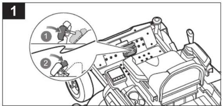
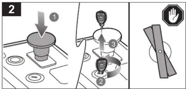
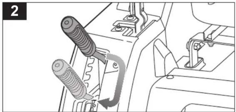
EN ■ Firmly hold the adjustment lever when setting the deck height, and release it only when it is secure in the preferred slot.
natural_image
Technical line drawing of a mechanical clamp or bracket assembly (no text or symbols)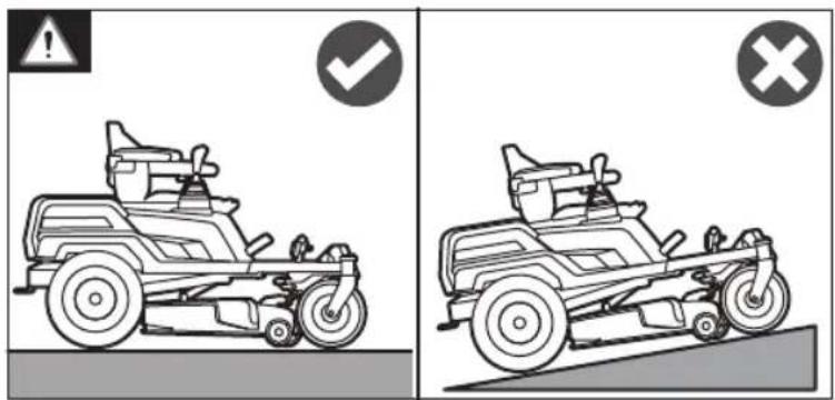

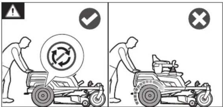
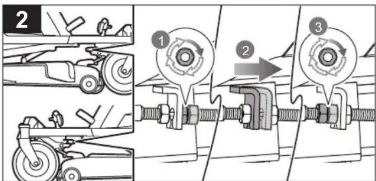
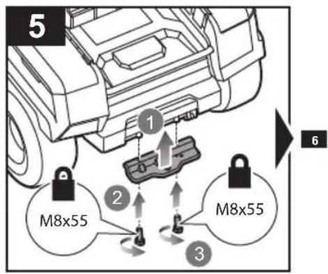
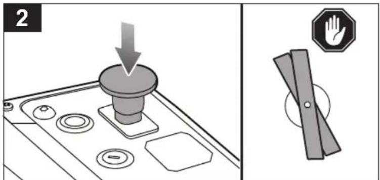
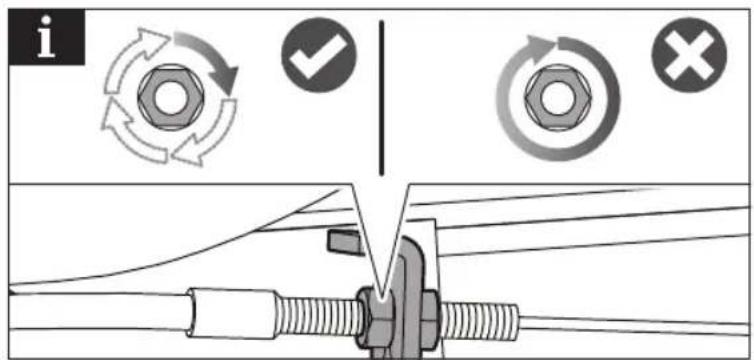
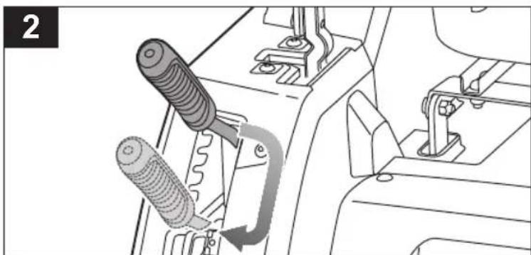
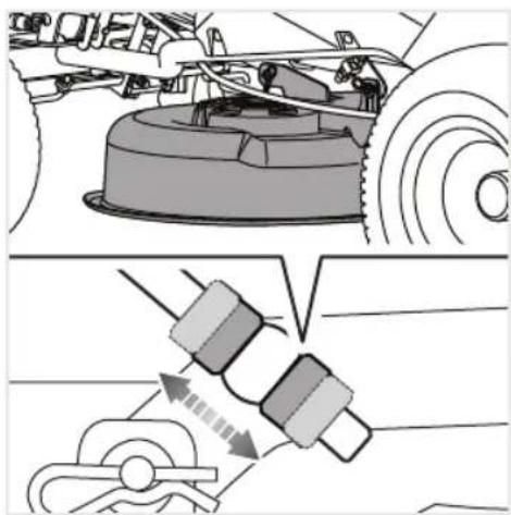
| EN | Stand behind the mower and try to push it forward. If the rear tyres turn, the brakes need to be tightened.Turn each adjustment nut 1/4 turn clockwise, then try again to push the mower.Continue rotating each nut 1/4 turn and testing until the mower can no longer be moved by pushing. |
| FR | Placez-vous derrière la tondeuse et essayez de la pousser vers l'avant. En cas de rotation des pneus arrière, les freins ont besoin d'être resserrés.Tourner chaque écrou de réglage d' 1/4 de tour dans le sens horaire, puis essayer à nouveau de pousser la tondeuse.Continuer à tourner chaque écrou d'1/4 de tour et à tester jusqu'à ce que la tondeuse ne puisse plus se déplacer lorsqu'elle est poussée. |
| DE | Stellen Sie sich hinter den Rasenmäher und versuchen Sie, ihn nach vorne zu schieben. Wenn sich die Hinterreifen drehen, müssen die Bremsen angezogen werden.Drehen Sie jede Einstellmutter eine Viertelumdrehung im Uhrzeigersinn und versuchen Sie dann erneut, den Rasenmäher zu schieben.Drehen Sie jede Mutter eine 1/4 Umdrehung weiter und testen Sie solange, bis sich der Rasenmäher durch Drücken nicht mehr bewegen lässt. |
| ES | Colóquese detrás del tractor cortacésped e intente empujarlo hacia delante. Si las ruedas traseras giran, será necesario apretar los frenos.Gire cada una de las tuercas de ajuste 1/4 de vuelta en el sentido de las agujas del reloj; a continuación, intente de nuevo empujar el cortacésped.Siga girando cada tuerca un cuarto de vuelta y realice la prueba hasta que el cortacésped no se pueda mover al empujarlo. |
| IT | Stare dietro al tosaerba e provare a spingerlo in avanti. Se le ruote posteriori girano, i freni devono essere stretti.Ruotare ogni dado di regolazione di 1/4 giro in senso orario e quindi provare di nuovo a spingere il tosaerba.Continuare la rotazione di ciascun dado di 1/4 giro e testare fino a quando il tosaerba non potrà essere più spostato spingendolo. |
| NL | Sta achter de maaier en probeer deze voorwaarts te duwen. Als de achterwielen draaien, moeten de remmen worden aangehaald.Draai elke stelmoer een kwartslag met de klok mee en probeer dan opnieuw de maaier te duwen.Blijf elke moer een kwartslag draaien en test totdat de maaier niet meer kan worden bewogen door te duwen. |
| PT | Mantenha-se atrás do corta-relvas e tente empurrá-lo para a frente. Se os pneus traseiros girarem, os travões têm de ser apertados.Rode cada porca de ajuste 1/4 volta no sentido dos ponteiros do relógio e, em seguida, tente novamente empurrar o corta-relvas.Continue a rodar cada porca 1/4 volta e a testar até que o corta-relvas já não possa ser movido ao empurrar. |
| DA | Stå bag plæneklipperen, og forsøg at skubbe den fremad. Hvis bagdækkene drejer rundt, trænger bremserne til at blive strammet.Drej hver justeringsmøtrik 1/4 omdrejning med uret, og prøv så igen at skubbe plæneklipperen.Fortsæt med at rotere hver møtrik 1/4 omdrejning og test, indtil plæneklipperen ikke længere kan flyttes ved at skubbe. |
| SV | Ställ dig bakom gräsklipparen och försök att skjuta den framat. Om bakdäcken vrids måste bromsarna dras åt.Vrid varje justeringsmutter 1/4 varv medurs och försök sedan att skjuta på klipparen igen.Fortsätt rotera varje mutter 1/4 varv och testa tills gräsklipparen inte längre kan flyttas genom alt skjuta på den. |
| FI | Seiso leikkurin takana ja yritä työntää sitä eteenpäin. Jos takarenkaat pyörivät, jarruja on kiristettävä.Käännä kutakin säätömutteria 1/4 kierrosta myötäpäivään ja yritä sitten työntää leikkuria uudelleen.Jatka kääntämällä kutakin mutteria 1/4 kierroksen verran ja testaa, kunnes leikkuria ei enää voida liikuttaa työntämällä. |
| NO | Stå bak klipperen og prøv å dytte den fremover. Hvis bakhjulene snurrer, må bremsene strammes.Skru hver justeringsmutter 1/4 gang med klokken, og prøv å skyve klipperen igjen.Fortsett å skru hver mutter 1/4 gang og teste til klipperen ikke lenger kan flyttes ved å skyve. |
natural_image
Mechanical diagram showing a lever mechanism with a shopping cart and a cup, no text or symbols present.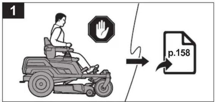
natural_image
Mechanical assembly diagram showing a lever mechanism with a spring and worm-like component (no text or symbols)
natural_image
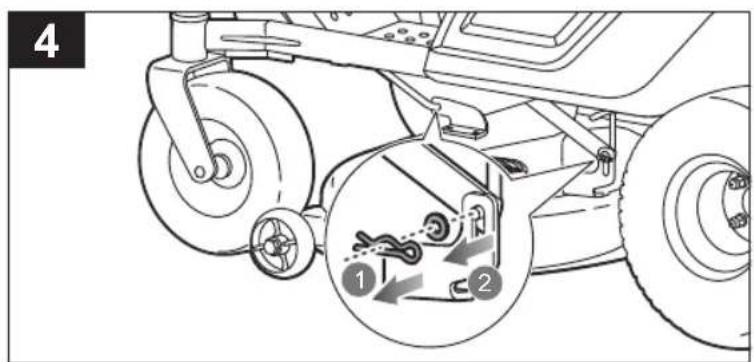
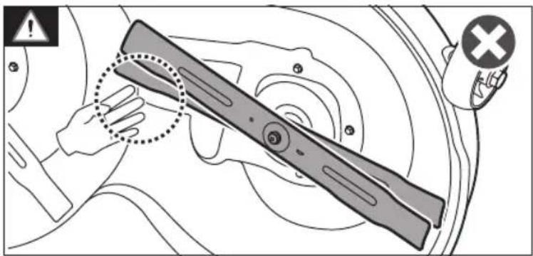
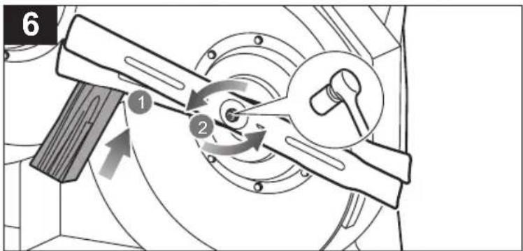
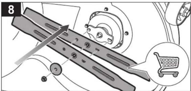
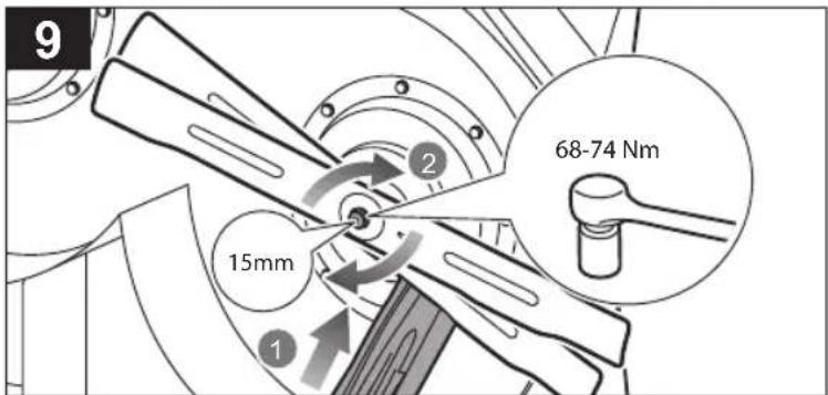
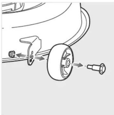
Mechanical assembly diagram showing a wheel and mounting bracket with a highlighted component (no text or symbols)| EN | ■ Wear heavy-duty gloves at all times while handling the cutting deck. Keep hands and fingers clear of pinch points. Ensure that the blade is properly seated and the blade nut is tightened to the torque specification. |
| FR | ■ Portez des gants épais en tout temps lorsque vous manipulez le carter de coupe. Tenez vos mains et vos doigts à l'écart des points de pincement. Vérifier que la lame est correctement installée et que l'écrou de lame est serré aux spécifications ci-dessus. |
| DE | ■ Tragen Sie beim Handhaben des Mähwerks jederzeit stabile Handschuhe. Halten Sie Hände und Finger von Quetschkanten fern. Stellen Sie sicher, dass die Klinge richtig sitzt und die Klingenmutter mit den oben angegebenen Drehmomenten festgezogen ist. |
| ES | ■ Utilice unos guantes resistentes en todo momento durante la manipulación de la base de corte. Mantenga las manos y los dedos alejados de los puntos con peligro de aplastamiento. Asegúrese de que la cuchilla esté bien asentada y que la tuerca de la cuchilla esté apretada al par de apriete especificado. |
| IT | ■ Indossare sempre guanti protettivi quando si maneggia la pedana di taglio. Tenere le mani e i piedi lontano dai punti di schiacciamento. Assicurarsi che la lama sia correttamente posizionata e che il dado della lama sia stretto alla coppia specificata. |
| NL | ■ Draag altijd handschoenen voor zwaar gebruik wanneer u het maaidek hanteert. Houd uw handen en vingers uit de buurt van afknellende plekken. Zorg ervoor dat het snijblad goed vastzit en dat de stelmoer is aangedraaid volgens de specificaties van het aanhaalmoment. |
| PT | ■ Use luvas grossas sempre que manusear a plataforma de corte. Mantenha as mãos e os dedos afastados dos pontos de esmagamento. Certifique-se de que a låmina está corretamente encaixada e a porca da låmina está apertada de acordo com a especificação do binário. |
| DA | ■ Brug til enhver tid kraftlige handsker, mens du håndterer klippedækket. Hold hænder og fingre fri af klemmepunkter. Sørg for, at klingen sidder korrekt, og at klingemøtrikken er strammet iht. momentspecifikationerne ovenfor. |
| SV | ■ Använd alltid krafliga handskar vid hantering av klippaggregatel. Håll händer och fingrar borta från klämpunkter. Se till att bladet sitter ordentligt och att bladmuttern är atdragen enligt specifikationerna ovan. |
| FI | ■ Käytä aina paksuja käsineitä, kun käsittelet leikkuulaitetta. Pidä kädet ja sormet loitolla puristumiskohdista. Varmista, että terä on kunnolla paikoillaan ja että terämutteri on kiristetty yllä mainittujen momenttien mukaan. |
| NO | ■ Bruk alltid tunge hansker när du håndterer klipperdekket. Hold hender og fingre fri for klempunkter. Forsikre deg om at kniven sitter sikkert og at knivmutteren er strammet til momentet som er angitt ovenfor. |
natural_image
Diagram of a car's lower body with wheels and a mechanical component, showing a directional arrow (no text or symbols)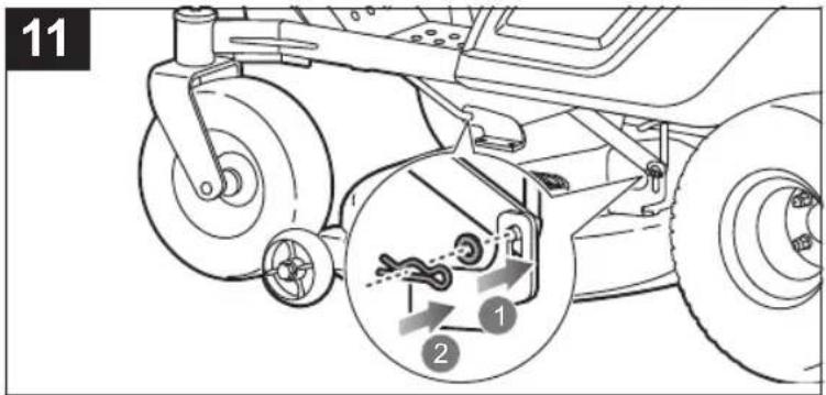
natural_image
Mechanical assembly diagram showing a wheel and adjustment components (no text or labels)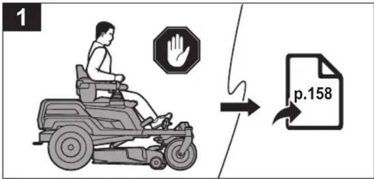
natural_image
Mechanical lever mechanism diagram showing pivot and feed components (no text or symbols)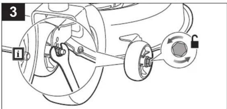
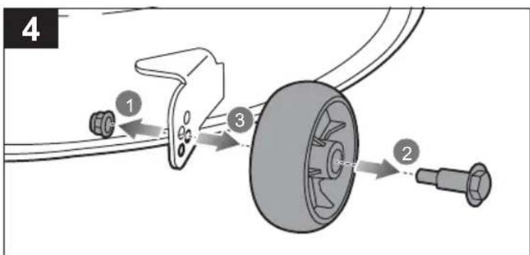
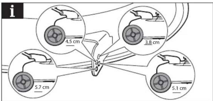
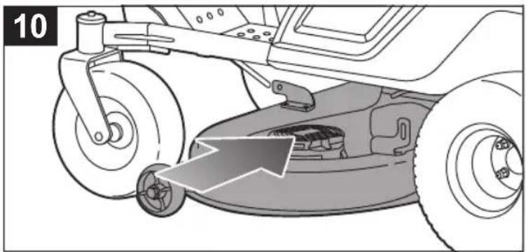
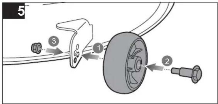
| EN | The cutting deck wheels should be positioned approximately 1.25 cm off the ground when the mower is at the preferred cutting height to minimise the chance of scalping the lawn. When shipped, the cutting deck wheels are set to the 3.8 cm position.Tighten the bolt to 5.4–8.1 Nm of torque. Make sure both wheels are in the same position. |
| FR | Les roues du carter de coupe doivent être positionnées à environ 1,25 cm du sol lorsque la tondeuse est réglée à la hauteur de coupe souhaitée afin de réduire le risque de dénuder la terre. À la livraison, les roues du carter de coupe sont réglées à 3,8 cm.Serrer le boulon à un couple de 5,4-8,1 Nm. Assurez-vous que les deux roues sont dans la même position. |
| DE | Wenn der Rasenmäher auf die bevorzugte Schneidehöhe eingestellt ist, sollten die Mähwerkräder etwa 1,25 cm über dem Boden positioniert sein, damit das Risiko, den Rasen bis zum Boden zu schneiden, minimiert wird. Im Auslieferungszustand sind die Mähwerkräder auf 3,8 cm eingestellt.Ziehen Sie den Bolzen mit einem Anzugsmoment von 5,4 bis 8,1 Nm fest. Stellen Sie sicher, dass beide Räder in die gleiche Richtung ausgerichtet sind. |
| ES | Las ruedas de la base de corte deben estar situadas a aproximadamente 1,25 cm del suelo cuando el cortacésped tiene ajustada la altura de corte deseada para minimizar las probabilidades de que se realice un corte superficial del césped. Cuando se envía el producto, las ruedas de la base de corte están ajustadas en la posición de 3,8 cm.Apriete el perno a un par de 5,4–8,1 Nm. Asegúrese de que las dos ruedas estén en la misma posición. |
| IT | Le ruote della pedana di taglio devono essere posizionate a circa 1,25 cm lontano da terra quando il tosaerba è all'altezza di taglio prescelta per ridurre al minimo la possibilità di rovinare l'erba. Quando spedito, le ruote della pedana di taglio sono impostate alla posizione di 3,8 cm.Stringere il bullone a 5,4–8,1 Nm di coppia. Assicurarsi che entrambe le ruote siano nella stessa posizione. |
| NL | De wielen van het maaidek moeten ongeveer 1,25 cm boven de grond zijn afgesteld wanneer de maaier zich op de gewenste maaihoogte bevindt, om te voorkomen dat het gras wordt weggeschraapt. Bij verplaatsing moeten de maaidekwielen in de stand op 3,8 cm hoogte worden gezet.Haal de bout aan tot een aanhaalmoment van 5,4–8,1 Nm. Zorg ervoor dat beide wielen in dezelfde stand staan. |
| PT | As rodas da plataforma de corte deverão estar posicionadas a, aproximadamente, 1,25 do chão quando o corta-relvas estiver na sua posição de corte preferida para minimizar a possibilidade de danificar o relvado. Quando enviadas, as rodas da plataforma de corte estão reguladas para a posição de 3,8 cm.Aperte o parafuso a um binário de aperto de 5,4–8,1 Nm. Certifique-se de que ambas as rodas estão na mesma posição. |
| DA | Klippedækkets hjul skal være placeret ca. 1,25 cm over jorden, när klipperen er i den foretrukne klippehøjde, for at minimere risikoen for at skrælle plænen. Ved afsendelse bliver klippedækkets hjul indstillet til positionen 3,8 cm.Spænd bolten med et tilspændingsmoment på 5,4-8,1 Nm. Sikr dig, at begge hjul er i samme position. |
| SV | Klippaggregatets hjul bör placeras ca. 1,25 cm från marken när gräsklipparen är på den önskade klipphøjden för att minimera risken för att gräsmattan blir för kort. Vid leverans är klippaggregatets hjul inställda på 3,8 cm.Dra åt bullen med ett moment på 5,4–8,1 Nm. Säkerställ att båda hjulen är i samma position. |
| FI | Leikkuulaitteen pyörät tulee asettaa noin 1,25 cm:n korkeudelle maasta, kun leikkuri on toivotulla leikkuukorkeudella. Näin voidaan välttää nurmikon irtoamisen vaara. Kun kone toimitetaan, leikkuulaitteen pyörät on asennettu 3,8 cm:n korkeudelle.Kiristä pultti 5,4–8,1 Nm:n kirstysmomenttiin. Varmista, että molemmat pyörät ovat samassa asennossa. |
| NO | Kuttedekkhjulene skal posisjoneres omtrent 1,25 cm opp fra bakken när klipperen er i foretrukket klippehøyde for å minimere muligheten for å skalpere plenen. Ved levering er klipperdekkhjulene stilt inn på 3,8 cm.Trekk til bolten til 5,4–8,1 Nm moment. Se til at begge hjulene er i samme stilling. |


natural_image
Mechanical assembly diagram showing gear and belt drive mechanism (no text or labels)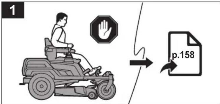
natural_image
Diagram of a car's seatbelt mechanism with an arrow indicating clockwise motion (no text or symbols)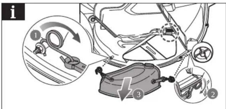
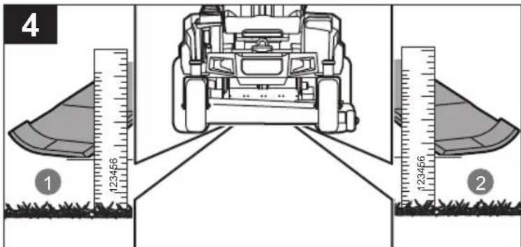
| EN | For side-to-side adjustment, turn the blades so that these point at the sides of the cutting deck. On the outside edge of each blade, measure the distance from the bottom edge to the ground. If the distance between the two sides is greater than 3.1 mm (1/8 in.), an adjustment is necessary.For front-to-back adjustment, the front tip of the blade should be between 3.2 mm and 9 mm lower than the rear tip. Make sure to turn the adjustment nuts on both sides equally to prevent throwing off the side-to-side measurement.Turn the adjustment nuts clockwise to raise or counterclockwise to lower the side of the cutting deck. |
| FR | Pour un réglage transversal, tournez les lames de façon à ce qu'elles pointent vers les côtés du carter de coupe. Sur le bord extérieur de chaque lame, mesurez la distance entre le bord inférieur et le sol. Si la distance entre les deux côtés est supérieure à 3,1 mm. (1/8 in.), un ajustement transversal est nécessaire.Pour l'ajustement longitudinal, la pointe avant de la lame doit être entre 3,2 mm et 9 mm plus basse que la pointe arrière. Tourner de façon égale les écrous de réglage se trouvant de chaque côté afin d'éviter de fausser les mesures transversales.Tournez les écrous de réglage dans le sens horaire pour rehausser le côté du carter de coupe, ou dans le sens anti-horaire pour l'abaisser. |
| DE | Um sie Seite an Seite auszurichten, drehen Sie die Messer so, dass sie auf die Seiten des Mähwerks zeigen. Messen Sie an der Außenkante jedes Messers den Abstand zwischen der Unterkante des Messers und dem Boden. Wenn der Abstand zwischen den beiden Seiten größer als 3,1 mm (1/8 Zoll) ist, muss eine Einstellung vorgenommen werden.Für die Längsjustierung sollte die vordere Messerspitze zwischen 3,2 mm und 9 mm niedriger als die hintere Messerspitze liegen. Achten Sie darauf, die Verstellmuttern auf beiden Seiten gleichmäßig zu drehen, um ein Hin- und Herbewegen zu vermeiden.Drehen Sie die Verstellmuttern im Uhrzeigersinn, um die Seite des Mähwerks anzuheben, oder gegen den Uhrzeigersinn, um sie abzuskenken. |
| ES | Para realizar el ajuste de lado a lado, gire las cuchillas de forma que estas queden orientadas hacia los laterales de la base de corte. En el borde exterior de cada cuchilla, mida la distancia desde el borde inferior hasta el suelo. Si la distancia entre los dos lados es superior a 3,1 mm (1/8 in), será necesario realizar un ajuste.Para el ajuste entre la parte delantera y trasera, la punta delantera de la cuchilla debería estar entre 3,2 mm y 9 mm por debajo de la punta trasera. Asegürese de girar las tuercas de ajuste de los dos lados de forma similar para no modificar la medición de lado a lado.Gire las tuercas de ajuste en el sentido de las agujas del reloj para subir el lado de la base de corte o en el sentido contrario al de las agujas del reloj para bajarlo. |
| IT | Per una regolazione da lato a lato, girare le ruote in modo che puntino verso la pedana di taglio. Sul bordo esterno di ciascuna lama, misurare la distanza dal bordo inferiore a terra. Se la distanza tra i due lati è superiore a 3,1 mm (1/8 pollici), è necessaria una regolazione.Per la regolazione posteriore, la punta anteriore della lama deve essere tra 3,2 mm e 9 mm in meno rispetto alla punta posteriore. Assicurarsi di girare i dadi di regolazione su entrambi i lati allo stesso modo per impedire di eliminare la misurazione laterale.Ruotare i dadi di regolazione in senso orario per alzare e in senso anteriorario per abbassare il lato della pedana di taglio. |
| NL | Voor zijwaartse afstelling moeten de messen zodanig worden gedraaid dat ze naar de zijkanten van het maaidek wijzen. Meet aan de buitenste rand van elk mes de afstand van de onderrand tot de grond. Als het verschil tussen de twee zijkanten groter is dan 3,1 mm (1/8e inch) moet dit worden afgesteld.Voor het verstellen van de voor- en achterkant moet de voorste punt van het blad tussen 3,2 mm en 9 mm lager zijn dan de achterste punt.Zorg ervoor dat de stelmoeren aan beide zijden evenveel zijn verdraaid om te voorkomen dat de meting van links naar rechts niet correct is.Draai de stelmoeren rechtsom voor het omhoog zetten of linksom voor het omlaag zetten van het maaidek. |
| PT | Para o ajuste lado a lado, rode as lâminas de modo a que fiquem a apontar para os lados da plataforma de corte. Na aresta exterior de cada lâmina, meça a distância da aresta inferior ao solo. Se a distância entre os dois lados for inferior a 3,1 mm (1/8 pol.), è necessário ajustar.Para o ajuste da frente para trás, a ponta frontal da lâmina deve estar entre 3,2 mm e 9 mm abaixo da ponta traseira. Certifique-se de que roda as porcas de ajuste em ambos os lados de forma igual para evitar o desnível da medição lado a lado.Roda as porcas de ajuste para a direita para levantar ou para a esquerda para baixar o lado da plataforma de corte. |
| DA | For justering fra side til side skal du dreje klingerne, så de peger mod klippedækkets sider. På den udvendige kant af hvert klinge måles afstanden fra nederste kant til jorden. Hvis afstanden mellem de to sider er større end 3,1 mm (1/8 tomme), er det nødvendigt med en justering.Til justering af front til bag skal knivens forreste spids være mellem 3,2 mm og 9 mm lavere end den bageste spids Sørg for at dreje justeringsmøtrikkerne på begge sider lige meget for at forhindre, at måling fra side til side tilsidesættes.Drej justeringsmøtrikkerne med uret for at hæve eller mod uret for at sænke siden på klippedækket. |
| SV | För justering sida till sida, vrid bladen så att dessa pekar mot sidorna av klippaggregatet. På ytterkanten av varje blad, mät avständet från den nedre kanten till marken. Om avständet mellan de två sidorna är større än 3,1 mm krävs en justering.Vid justering från framsida till baksida bör den främre bladspetsen vara mellan 3,2-9 mm lägre än den bakre spetsen. Se till att vrida justeringsmuttrarna på båda sidor lika mycket för att förhindra att mätningen från sida till sida blir fel.Vrid justeringsmuttrarna medurs för att höja eller moturs för att sänka klippaggregatets sida. |
| FI | Jos haluat säätää sivusuunnassa, käännä terät siten, että ne osoittavat leikkuulaitteen sivuille. Mittaa kunkin terän ulkoreunalta etäisyys terän alareunasta maahan. Jos kahden sivun välinen etäisyys on yli 3,1 mm (1/8 tuumaa), säätö on tarpeen.Terän etukärjen on oltava 3,2–9 mm matalampi kuin takakärki, jotta sitä voidaan säätää edestä taakse. Muista kääntää säältömuttereita molemmilla puolilla tasaisesti, jotta sivulta sivulle mittaus ei heiltäisi.Käännä säätömuttereita myötäpäivään nostaaksesi tai vastapäivään madaltaaksesi leikkuulaitteen sivua. |
| NO | For side-til-side-justering, snu bladene slik at disse peker på sidene av klipperdekket. På utsiden av hvert blad måler du avstanden fra nederste kant til bakken. Hvis avstanden mellom de to sidene er større enn 3,1 mm (1/8 tomme), er det nødvendig med en justering.For front-til-bak-justering skal frontspissen på bladet være mellom 3,2 mm og 9 mm lavere enn bakspissen. Pass på at du virir justeringsmutterne på begge sider like mye for å unngå skjev justering side-til-side.Vri justeringsmutteren med klokken for å heve eller mot klokken for å senke siden av klipperdekket. |
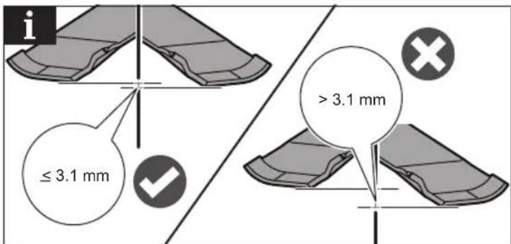
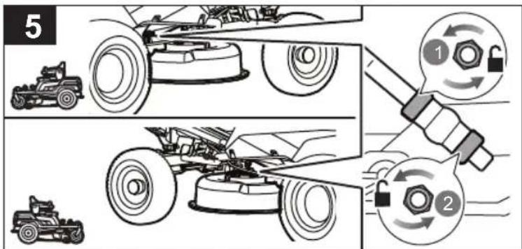
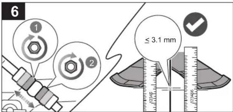
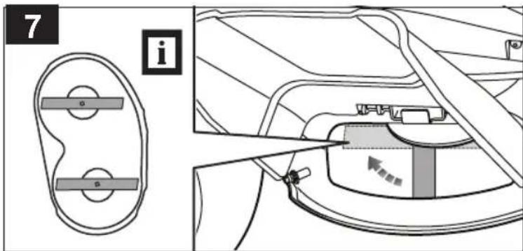
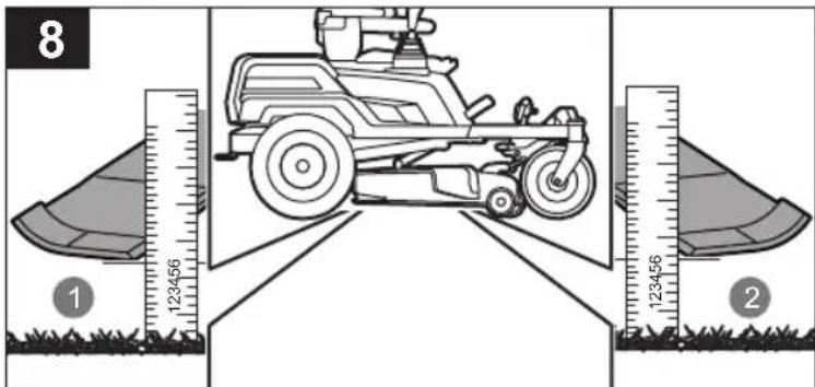
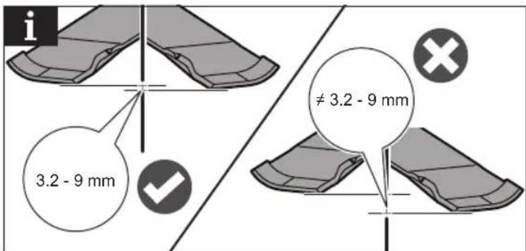
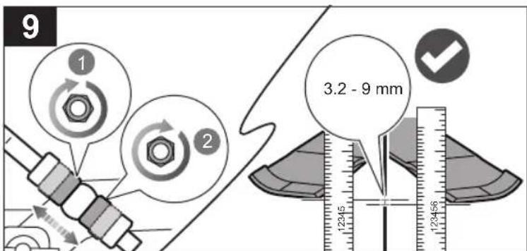
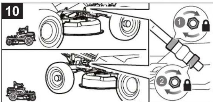
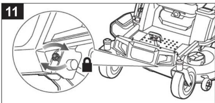
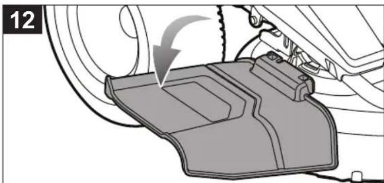
natural_image
Mechanical assembly diagram showing a component being inserted into a housing, with no visible text or symbols.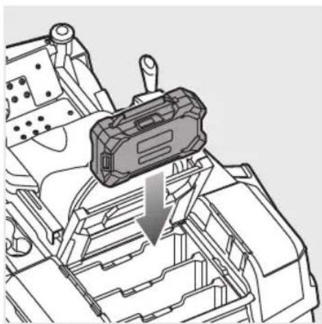
natural_image
Technical line drawing of a mechanical component with a downward arrow indicating a process or assembly (no text or symbols present)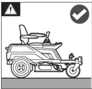
natural_image
Line drawing of a mobile vehicle with wheels and control panel, accompanied by warning symbols (no text or labels)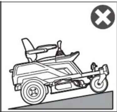
natural_image
Line drawing of a small electric scooter on a ramp, with a cross symbol in the corner (no text or labels)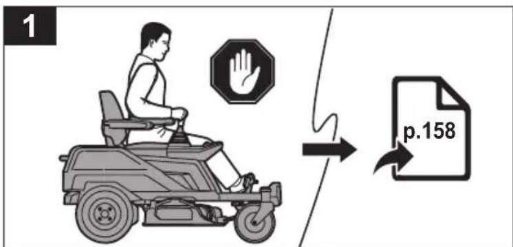
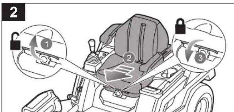
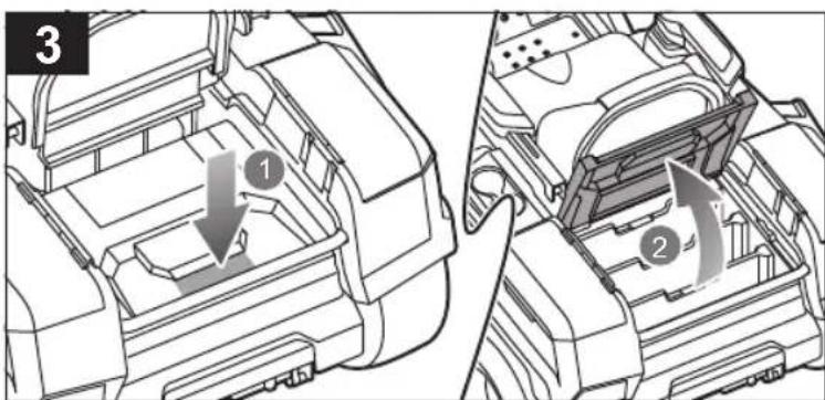
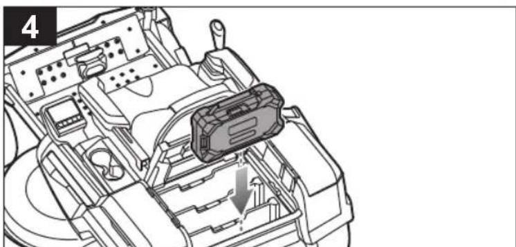
natural_image
Technical line drawing of a vehicle engine compartment with a highlighted component (no text or symbols)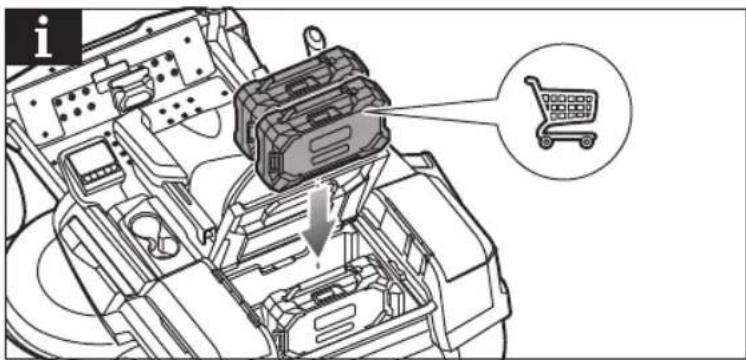
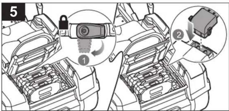
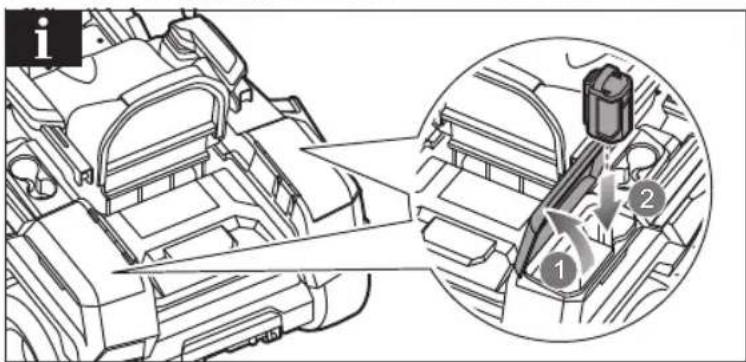
p.158
| EN | Charge the product indoors, in a well-ventilated area. Do not charge the product in a confined space. The batteries charge best at temperatures from 0 °C to 38 °C. |
| FR | Chargez les produits à l'intérieur, dans une zone bien ventilée. Ne pas charger le produit dans un espace confiné. Pour être optimale, la charge des batteries doit s'effectuer à une température comprise entre 0 °C et 38 °C. |
| DE | Laden Sie das Gerät in einem Innenraum an einem gut belüfteten Ort auf. Laden Sie das Gerät nicht in einem engen Raum auf. Die Akkus laden sich am besten bei Temperaturen von 0 °C bis 38 °C auf. |
| ES | Cargue el producto en un espacio interior, en una zona con una ventilación adecuada. No cargue el producto en un espacio angosto. Las baterías se cargan mejor a temperaturas comprendidas entre 0 °C y 38 °C. |
| IT | Caricare il prodotto all'interno in un'area ben arieggiata. Non caricare il prodotto in uno spazio confinato. Le batterie si caricano meglio a temperature a partire dai 0°C ai 38°C. |
| NL | Laad het product binnenshuis op, in een goed geventileerde ruimte. Laad het product niet op in een afgesloten ruimte. De batterijen worden het best opgeladen bij temperaturen tussen 0°C en 38 °C. |
| PT | Carregue o produto numa área interior e bem ventilada. Não carregue o produto num espaço confinado. As baterias carregam melhor em temperaturas de 0 °C a 38 °C. |
| DA | Oplad produktet indendørs på et velventileret område. Oplad ikke produktet, hvor der er begrænset plads. Batterier oplades bedst ved temperaturer fra 0°C til 38°C. |
| SV | Ladda produkten inomhus, i ett välventilerat område. Ladda inte produkten i ett trängt utrymme. Batterierna laddas bäst vid temperaturer från 0 °C till 38 °C. |
| FI | Lataa tuote hyvin ilmastoidussa sisätilassa. Älä lataa tuotetta suljetussa tilassa. Akut latautuvat parhaiten lämpötiloissa välillä 0 °C – 38 °C. |
| NO | Lad produktet innendørs, på et sted med god ventilasjon. Ikke lad produktet i trange områder. Batteriene lader best i temperaturer fra 0 °C til 38°C. |
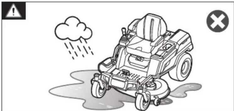
natural_image
Illustration of a cartoon-style mobility vehicle with rain and cloud, no text or symbols present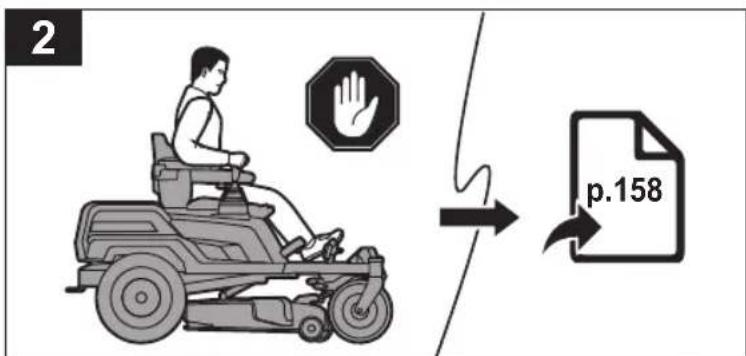
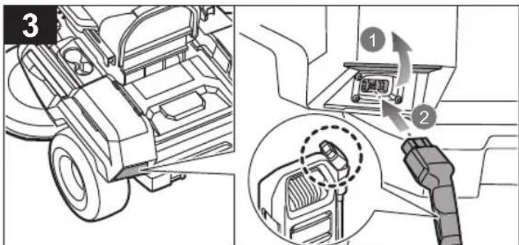
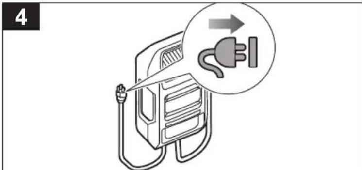
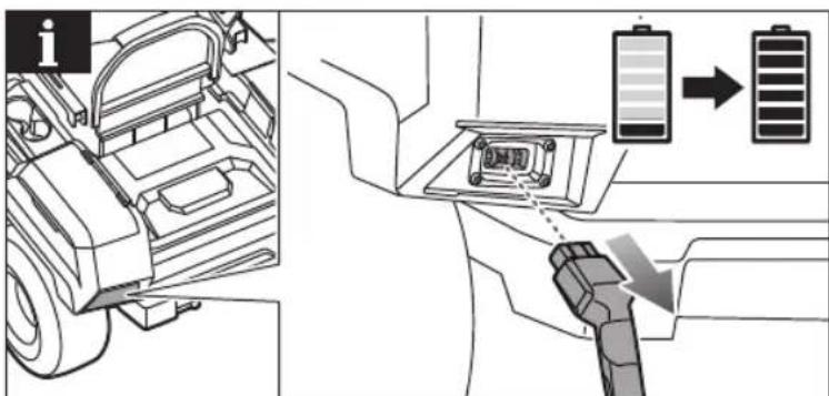


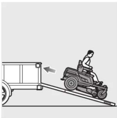
natural_image
Illustration of a person riding a motorized cart on an inclined ramp, with an arrow indicating motion direction (no text or symbols)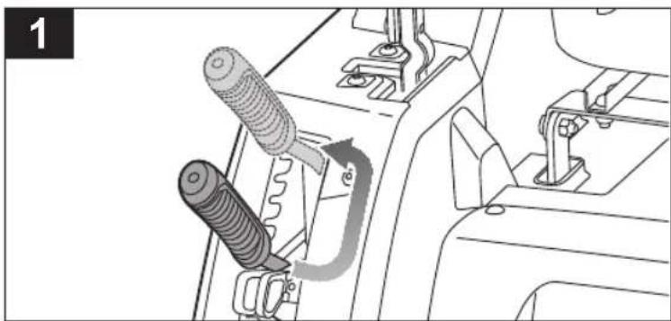
natural_image
Diagram of a car's internal gear shift lever mechanism, showing two components with no text or symbols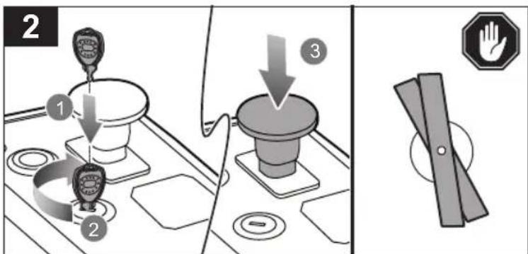
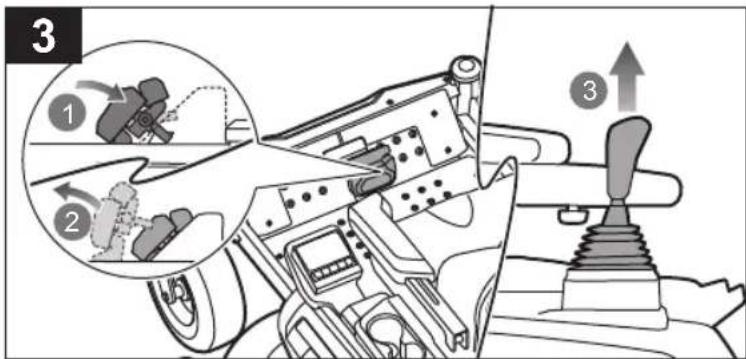
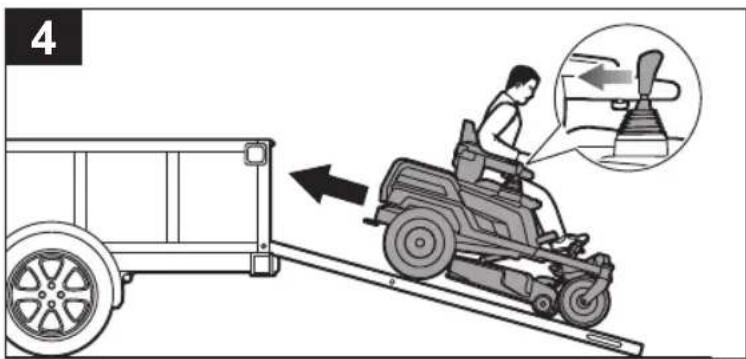
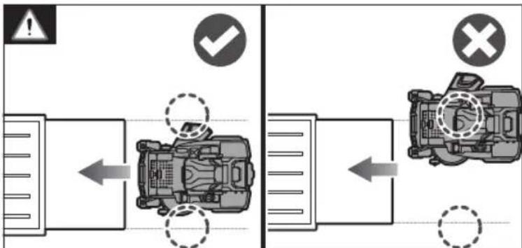
EN ■ Set the cutting deck to the maximum height.
■ Insert the start key, and turn the key to the ON position. Push the blade engage knob to stop the blades.
■ Step on the brake pedal to disengage the parking brake. Pull up the joystick.
■ Slowly drive the mower backwards onto the ramp and into the trailer.
The declared vibration total values and the declared noise emission values given in this instruction manual have been measured in accordance with a standardised test and may be used to compare one tool with another. They may be used for a preliminary assessment of exposure.
The declared vibration and noise emission values represent the main applications of the tool. However, if the tool is used for different applications, used with different accessories, or poorly maintained, the vibration and noise emission may differ. These conditions may significantly increase the exposure levels over the total working period. An estimation of the level of exposure to vibration and noise should take into account the times when the tool is turned off or when it is running idle. These conditions may significantly reduce the exposure level over the total working period.
Identify additional safety measures to protect the operator from the effects of vibration and noise, such as maintaining the tool and the accessories, keeping the hands warm (in case of vibration), and organising work patterns.
FR
AVERTISSEMENT
EN RYOBI WARRANTY APPLICATION CONDITIONS
In addition to any statutory rights resulting from the purchase, this product is covered by a warranty as stated below.
- The warranty period is 24 months for consumers and commences on the date when the product was purchased. This date has to be documented by an invoice or other proof of purchase. The product is designed and dedicated to consumer and private use only. So there is no warranty provided in case of professional or commercial use. This warranty applies only on new products.
- There is a possibility to extend for a part of the range of power tools (AC/DC) the warranty period over the period described above using the registration on the www.ryobitools.eu website. The eligibility of products for extended warranty is clearly displayed in stores and / or on packaging and is contained within the product documentation. The end user is required to register his/her newly-acquired products online within 30 days from the date of purchase. The end user may register for the extended warranty in his/her country of residence if listed on the online registration form where this option is valid. Furthermore, end users must give their consent to the storage of their personal data that is required to be entered online. They must also accept the terms and conditions. The registration confirmation receipt, which is sent out by e-mail, and the original invoice showing the date of purchase will serve as proof of the extended warranty.
- The warranty covers all defects of the product during the warranty period due to faults in workmanship or material at the purchase date. The warranty is limited to repair and/or replacement and does not include any other obligations including but not limited to incidental or consequential damages. The warranty is not valid if the product has been misused, used contrary to the instruction manual, or has been incorrectly connected to a power supply. This warranty does not apply to:
– any damage to the product that is the result of improper or lack of maintenance
– any product that has been altered or modified
– any product where original identification (trade mark, serial number) markings have been defaced, altered or removed
– any damage caused by non-observance of the instruction manual
– any product not displaying the CE approval mark on the rating plate
– any product that has been attempted to be repaired by a non-authorised warranty service centre or without prior authorisation by Techtronic Industries
– any product connected to improper power supply (amps, voltage, frequency)
– any product used with inappropriate fuel mixture (fuel, oil, ratio of oil/ fuel mixture)
– any damage caused by external influences (water, chemical, physical, shocks) or foreign substances
– normal wear and tear spare parts
– inappropriate use, overloading of the tool
– use of non-approved accessories or parts
- Accessories provided with the tool or purchased separately including but not limited to blades, saw chains, cutting lines, etc.
– Any periodic adjustments to or maintenance cleaning of carburettors
- Components (parts and accessories) subject to natural wear and tear, including but not limited to bump knobs, drive belts, clutch, blades of hedge trimmers or lawn mowers, harness, cable throttle, carbon brushes, power cord, tines, felt washers, hitch pins, blower fans, blower and vacuum tubes, vacuum bag and straps, guide bars, saw chains, hoses, connector fittings, spray nozzles, wheels, spray wands, inner reels, outer spools, cutting lines, spark plugs, air filters, gas filters, mulching blades, etc.
- For servicing, the product must be sent or presented to a RYOBI authorised service station listed for each country in the following list of service station addresses. In some countries your local RYOBI dealer undertakes to send the product to the RYOBI service organisation. When sending a product to a RYOBI service station, the product should be safely packed without any dangerous contents such as petrol, marked with sender's address and accompanied by a short description of the fault.
- A repair / replacement under this warranty is free of charge. It does not constitute an extension or a new start of the warranty period. Exchanged parts or products become our property. In some countries delivery charges or postage will have to be paid by the sender. Your statutory rights arising from the purchase of the product remain unaffected.
- This warranty is valid in the European Community, Switzerland, Iceland, Norway, Liechtenstein, Turkey, Russia, and the United Kingdom. Outside these areas, please contact your authorised RYOBI dealer to determine if another warranty applies.
AUTHORISED SERVICE CENTRE
Any request or issue with the product can be addressed to your local authorised service centres (visit www.ryobitools.eu) or directly to: Techtronic Industries GmbH, Max Eyth Straße 10, 71364 Winnenden, Germany. Please state the serial number and product type printed on the label.
FR RYOBI CONDITIONS D'APPLICATION DE LA GARANTIE
EN EC DECLARATION OF CONFORMITY
Zero-turn mower
Brand: RYOBI | Manufacturer ^1 | Model number ^2 | Serial number range ^3
We declare as the manufacturer under our sole responsibility that the product
mentioned below fulfills all the relevant provisions of the following European Directives,
European Regulations and harmonised standards ^4
Measured sound power level.... 96.8 dB(A)
Guaranteed sound power level.... 99 dB(A)
Conformity assessment method to Annex VI Directive 2000/14/EC amended by
2005/88/EC.
Notified body ^5
Authorised to compile the technical file: ^6
FR DÉCLARATION CE DE CONFORMITÉ
Max-Eyth-Straße 10, 71364 Winnenden, Germany
^2 RY72ZTRX107
^3 48649501000001 - 48649501999999
4 2006/42/EC, 2014/30/EU, 2000/14/EC, 2005/88/EC, 2011/65/EU,
EN ISO 12100: 2010, EN 62841-1: 2015, EN ISO 5395-1: 2013+A1:2017, EN ISO 5395-3: 2013+A1:2017+A2:2018, EN 55014-1:2021, EN 55014-2:2021, EN 61000-3-2:2019+A1, EN 61000-3-3:2013+A1
^5 No. 0197 – TÜV Rheinland LGA Products GmbH
Tillystrasse 2, 90431 Nürnberg – Germany

Todd Chipner
Vice President, Quality – Asia
Winnenden, Dec. 28, 2022
^6 Alexander Krug, Managing Director
Techtronic Industries GmbH
Max-Eyth-Straße 10, 71364 Winnenden, Germany
GB-DECLARATION OF CONFORMITY
Manufacturer: Techtronic Industries GmbH
Max-Eyth-Straße 10, 71364 Winnenden, Germany
We declare as the manufacturer under our sole responsibility that the product mentioned below
Zero-turn mower
Brand: RYOBI
Model number: RY72ZTRX107
Serial number range: 48649501000001 - 48649501999999
fulfills all the relevant provisions of the following Regulations: S.I. 2008/1597 (as
amended), S.I. 2016/1091 (as amended), S.I. 2012/3032 (as amended), S.I.
2001/1701 (as amended) and that the following designated standards have been used:
BS EN ISO 12100: 2010, BS EN 62841-1: 2015,
BS EN ISO 5395-1: 2013+A1:2017,
BS EN ISO 5395-3: 2013+A1:2017+A2:2018, BS EN 55014-1:2021,
BS EN 55014-2:2021, BS EN 61000-3-2:2019+A1, BS EN 61000-3-
3:2013+A1
Measured sound power level: 96.8 dB(A)
Guaranteed sound power level: 99 dB(A)
Conformity assessment method to S.I. 2001/1701 Schedule 9 (as amended)
Approved body:
No. 0197 – TÜV Rheinland LGA Products GmbH
Tillystrasse 2, 90431 Nürnberg – Germany

Todd Chipner
Vice President, Quality – Asia
Winnenden, Dec. 28, 2022
Authorised to compile the technical file:
Techtronic Industries (UK) Ltd
Parkway
Marlow Bucks SL7 1YL
UK

12^
p
12°
12°


EN RYOBI is a trade mark of Ryobi Limited, and is used under license.
natural_image
Three vertical panels with diagonal striped patterns, no text or symbols present
Techtronic Industries GmbH
Max-Eyth-Straße 10,
71364 Winnenden, Germany
Techtronic Industries (UK) Ltd
Parkway
Marlow Bucks SL7 1YL
UK
099270007001-01