RY48141 - Electric mower RYOBI - Free user manual and instructions
Find the device manual for free RY48141 RYOBI in PDF.

User questions about RY48141 RYOBI
0 question about this device. Answer the ones you know or ask your own.
Ask a new question about this device
Download the instructions for your Electric mower in PDF format for free! Find your manual RY48141 - RYOBI and take your electronic device back in hand. On this page are published all the documents necessary for the use of your device. RY48141 by RYOBI.
USER MANUAL RY48141 RYOBI
Follow all instructions when assembling this riding lawn mower. If any parts are damaged or missing, those parts must be replaced before proceeding.

WARNING: To reduce the risk of injury, you must read and understand this assembly guide before attempting to assemble this product.
SAVE THIS GUIDE FOR FUTURE REFERENCE
■ Rules for Safe Assembly ....2
■ Symbols....3
■ Tools Needed....3
■ Unpacking 4
■ Loose Parts List....5
■ Assembly 6-7
■ Final Preparation ....8
RULES FOR SAFE ASSEMBLY

WARNING:
Strictly adhere to all torque wrench tightening specifications. Failure to do so could cause serious personal injury.
All information, illustrations, photographs, and specifications contained in this manual are based on the latest product information available at the time of publication. Due to updates or other changes, there may be some differences in this manual. We reserve the right to make product changes
at any time, without notice and without incurring any obligation to make the same or similar changes to any products previously built or sold.
■ Any person attempting to assemble this product must have proper training and experience. Read this manual carefully and follow all assembly procedures as described.
■ All assembly must be completed with the unit on a level surface.
SYMBOLS
| The following signal words and meanings are intended to explain the levels of risk associated with this product. SYMBOL SIGNAL MEANING | ||
 | DANGER: | Indicates a hazardous situation, which, if not avoided, will result in death or serious injury. |
 | WARNING: | Indicates a hazardous situation, which, if not avoided, could result in death or serious injury. |
 | CAUTION: | Indicates a hazardous situation, that, if not avoided, may result in minor or moderate injury. |
| NOTICE: | (Without Safety Alert Symbol) Indicates information considered important, but not related to a potential injury (e.g. messages relating to property damage). | |
| Some of the following symbols may be used on this product. Please study them and learn their meaning. Proper interpretation of these symbols will allow you to operate the product better and safer. SYMBOL NAME DESIGNATION/EXPLANATION | ||
| Safety Alert Indicates a potentia | personal injury hazard. | |
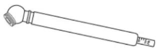
TOOLS NEEDED
The following tools (not included or drawn to scale) are needed for assembly:
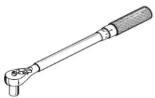
natural_image
Line drawing of a mechanical lever with handle and base (no text or symbols)TORQUE WRENCH
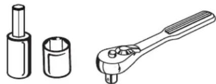
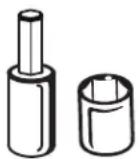
natural_image
Technical line drawings of mechanical components: a cylindrical tool, a cylindrical part with a shaft, and a wrench (no text or symbols)SOCKET WRENCH WITH 12 mm AND 14 mm SOCKETS AND 6 mm HEX BIT (IF NOT USING TOOL KIT PROVIDED)

TIRE PRESSURE GAUGE
UNPACKING
■ Remove the bolts securing the corner and side braces to the frame bottom, then lift the braces to remove.
- Cut the nylon straps securing the front and rear wheel axles to the frame.
■ Remove boxes containing loose parts, assembly hardware, and documentation.
■ Remove and set aside all accessible packaging and wrap from unit and parts. Do not discard the packing material until you have carefully inspected and satisfactorily operated the product.

WARNING:
If any parts on the Loose Parts List are already assembled to your product when you unpack it, verify the part is assembled correctly, is properly tightened, and is torqued correctly (where applicable) before proceeding to the next assembly step. Use of a product that may have been improperly assembled could result in death or serious personal injury.
■ Inspect the product carefully to make sure no breakage or damage occurred during shipping.
■ If any parts are damaged or missing, please call 1-800-525-2579 for assistance.
NOTE: Mower should be assembled while positioned on the frame bottom. Once assembly is complete, raise the cutting deck to its highest position, position a ramp next to the frame bottom, release the parking brake and slowly and carefully drive mower off frame.

WARNING:
Use extra care when driving the mower off of the frame. Press the low speed drive button and carefully move the drive levers and/or press the brake pedal as needed to control the speed. When driving the mower off of the frame, do not exceed the maximum recommended operation angle of 15^ . Failure to follow these instructions can result in loss of control and result in death, serious personal injury, or property damage.
NOTICE:
If no ramp is available, slowly and carefully drive the mower off the frame in reverse while looking down and behind. Driving the mower off the frame in the forward direction without a ramp can cause damage to the mower's cutting deck.
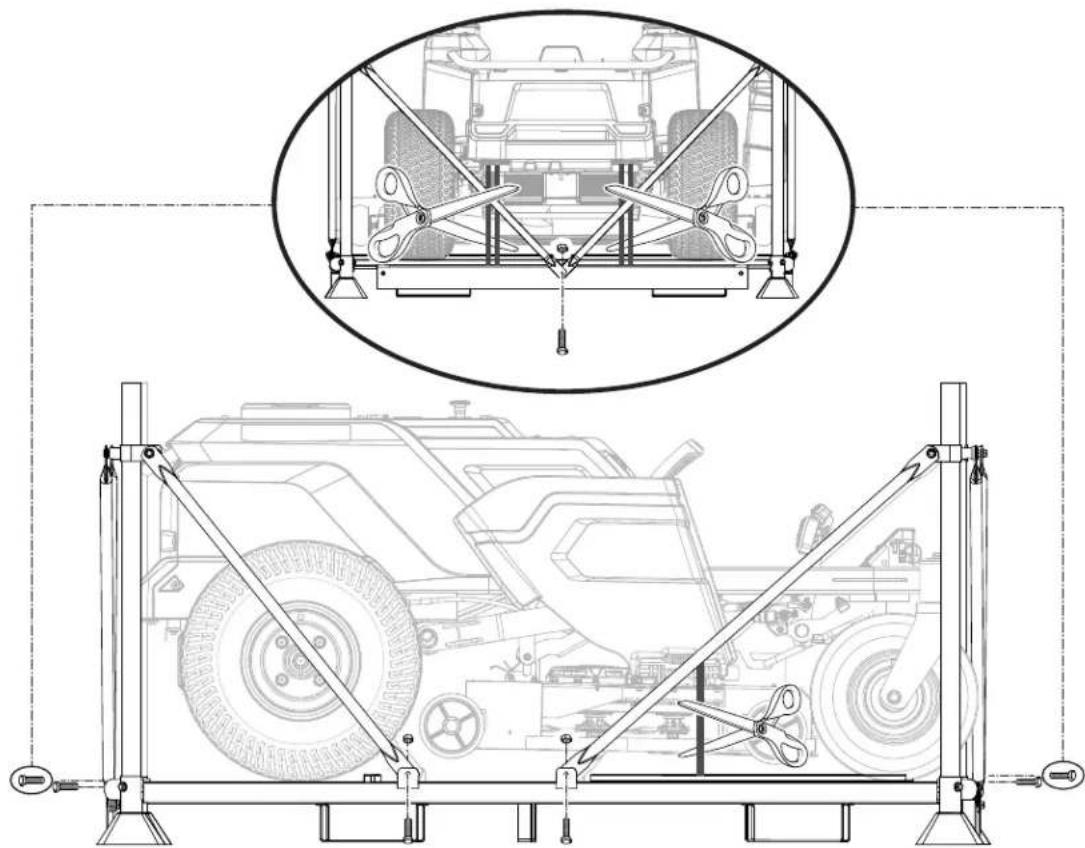
natural_image
Technical line drawing of a vehicle suspension system with a top-down view showing the chassis and equipment (no text or symbols present)LOOSE PARTS LIST
Key
No. Description Qty.
1 Seat Assembly with Safety Interlock Cable ..... 1
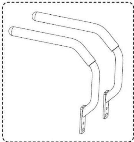
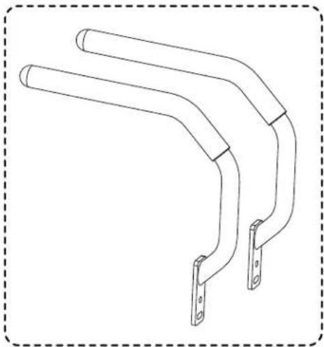
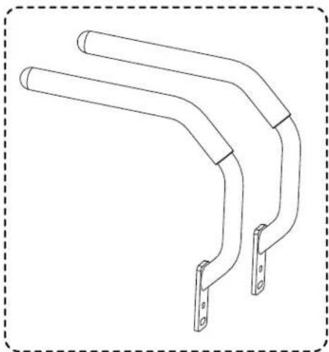
2 Drive Handles.... 2
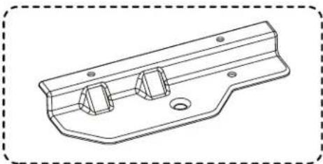
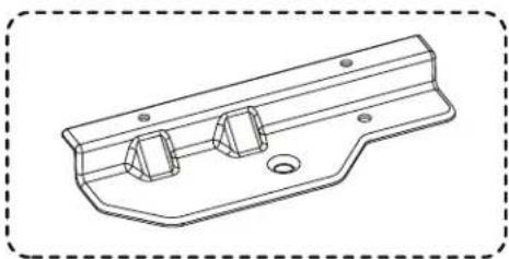
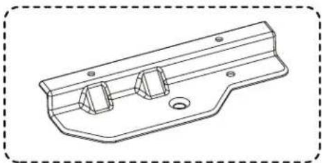
3 Towing Plate Assembly
Towing Plate .... 1
Bolts .... 2
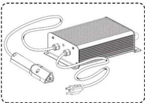
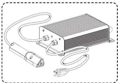
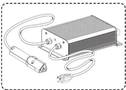
4 Charger 1
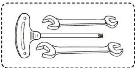
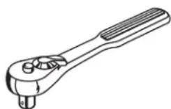
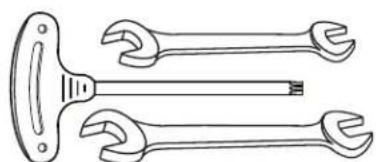
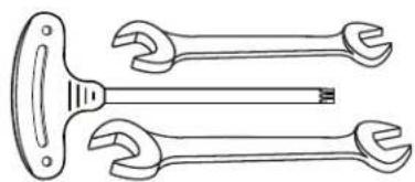
5 Tool Kit 2
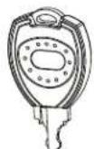
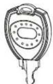
6 Keys 3
Key
No. Description Qty.
Assembly Guide (Not Shown)....1 Operator's Manual (Not Shown)....1

WARNING:
If any parts are damaged or missing do not assemble this product until the parts are replaced with new original manufacturer's parts or their equivalent. Assembly of this product with damaged, missing, or incorrect parts could result in serious personal injury.
1.
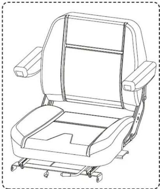
natural_image
Line drawing of a car seat assembly with no text or symbols2.
natural_image
Line drawing of three curved metal brackets with mounting holes, enclosed in a dashed border (no text or symbols)3.
natural_image
Technical line drawing of a mechanical bracket component (no text or symbols)4.
natural_image
Line drawing of an electronic device with a heat exchanger, connector, and power outlet (no text or symbols)5.
natural_image
Line drawing of a wrench with two different types of tools (no text or symbols)6.
natural_image
Line drawing of a key handle with a loop handle and handle, enclosed in a dashed border (no text or symbols)ASSEMBLY

WARNING:
Strictly adhere to all torque wrench tightening specifications. Failure to do so could cause serious personal injury.

WARNING:
Do not attempt to modify this product or create accessories not recommended for use with this product. Any such alteration or modification is misuse and could result in a hazardous condition leading to possible serious personal injury.

WARNING:
To prevent accidental starting that could cause serious personal injury, always remove the start key from the tool when you are assembling parts.
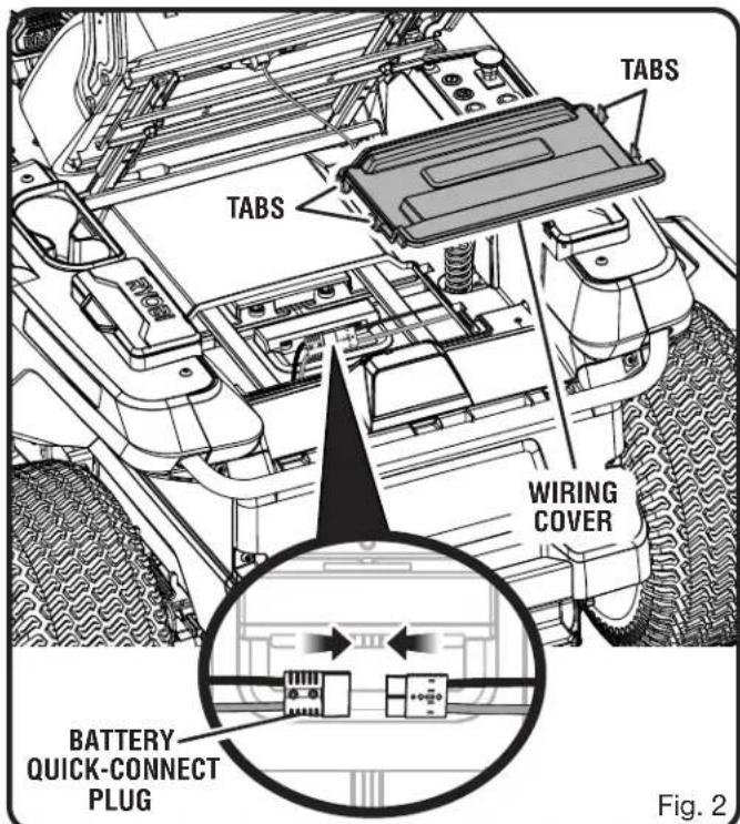
CONNECT THE BATTERY
See Figure 1.
When shipped from the factory, the mower's batteries are disconnected. To connect:
■ Press the tabs on the wiring cover. Lift the cover to gain access to the compartment below.
■ Connect the large battery quick-connect plug. This plug connects the batteries to the mower.
■ Reinstall the wiring cover and push down until it latches securely in place.
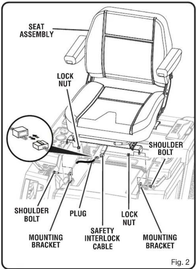
INSTALL THE SEAT
See Figure 2.
■ Remove the shoulder bolts and lock nuts from seat mountingbrackets.
■ Place the seat assembly over the mounting brackets and align holes as shown.
■ Reinstall shoulder bolts and lock nuts and tighten securely.
NOTE: Make sure the bolt heads are on the outside and the lock nuts are on the inside of the mounting bracket as shown and that the shoulder of the bolt is seated fully in the mounting bracket. This may be easier to do with the seat in the raised position.
■ Connect the safety interlock cable on the seat with the plug on the mower as shown.
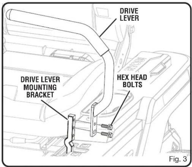
ASSEMBLY
■ Remove the hex head bolts from the drive lever mounting bracket.
■ Align the holes on the drive lever with the holes on the drive lever mounting bracket as shown.
■ Reinstall the bolts and tighten securely.
■ Repeat to install second drive lever.
NOTE: Make sure to use the same holes for mounting the drive lever on each side. The levers must be even once installed.
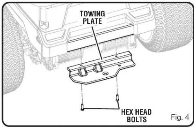
INSTALL THE TOWING PLATE
See Figure 4.
■ Align the holes in the towing plate with the holes in the rear crossmember.
■ Install two hex head bolts and tighten securely.
FINAL PREPARATION
CHECK TIRE PRESSURE
Check the air pressure in all tires before use. Improper air pressure will affect handling, steering response, traction, tire life, level cutting, and operator comfort. Be sure tires are inflated to the pressure shown below.
NOTE: Tire pressure should only be measured or adjusted when tires are cold.
| Recommended Pressure | Front Rear |
| 19 PSI 18 PSI |

WARNING:
Check the tire pressure carefully while inflating. Too much air in the tire could cause the tire to burst, causing serious personal injury.
VERIFY MOWER CONDITION
Inspect the entire product for damaged, missing, or loose parts such as screws, nuts, bolts, caps, etc. Tighten securely all fasteners and caps and do not operate this product until any missing or damaged parts are replaced.
CHARGE THE MOWER
See Figure 5.
Mower batteries must be charged overnight before first use. To verify mower batteries are fully charged, check the battery level indicator.
To charge:
■ Insert charger plug into charging port on mower, making sure it is properly connected.
■ Connect charger to power supply using normal household current of 120 V, AC only, 60 Hz.
■ Do not charge in an area of extreme heat or cold.
■ Remove the charger from the mower once it is fully charged and ready for use.
WARNING:
To avoid accidental starting or movement of the mower that could result in death or serious personal injury, always remove the start key and set the parking brake when leaving the mower unattended.
NOTICE:
Always connect the mower to the charger when the unit is not in use. If it is not possible to leave the mower charger connected, make sure to charge the batteries fully at least once a month.
This mower features a Safety Interlock System to protect the operator by shutting off the blades if the operator leaves the seat with the blades running. Test the system to be sure it is working correctly.
To test:
■ Position the mower on a level surface.
■ Set the parking brake.
■ Make sure drive levers are in the neutral position and the blade engage knob is down.
■ Install start key and turn to ON position.
■ Raise blade engage knob to activate blades.
■ Briefly lift off the seat, but do not get off the mower.
The blades should shut off within 5 seconds. If they don't, verify you connected the safety interlock cable as described on page 6. If the cable is connected but the system still doesn't function, contact customer service. Do not operate the mower until the safety interlock system has been repaired.
CHARGER
PLUG
CHARGING
PORT
Fig. 6
Fig. 5
TABLE DES MATIÈRES
natural_image
Technical line drawing of a mechanical wrench (no text or symbols)CLÉ DYNAMOMÉTRIQUE
JAUGE DE PRESSION
CLÉ À DOUILLE AVEC DOUILLES DE 12 mm ET 14 mm ET EMBOUT HEXAGONAL DE 6 mm (SI ON N'UTILISE PAS LE TROUSSE A OUTILS FOURNIES)
natural_image
Line drawing of a car seat assembly with no text or symbols2.
natural_image
Technical line drawing of two curved mechanical components with mounting holes (no text or symbols)3.
natural_image
Technical line drawing of a mechanical bracket component (no text or symbols)4.
natural_image
Illustration of an electronic device with a heat exchanger, connector, and power plug (no text or symbols)5.
natural_image
Line drawing of two wrenches with no text or symbols6.
ASSEMBLAGE

AVERTISSEMENT :
natural_image
Line drawing of a person using a mobility wheelchair in a motorized vehicle, no text or symbols presentÍNDICE DE CONTENIDO
natural_image
Line drawing of a car seat assembly with no text or symbols2.
natural_image
Technical line drawing of two curved mechanical components with mounting holes (no text or symbols)3.
natural_image
Technical line drawing of a mechanical bracket component (no text or symbols)4.
natural_image
Illustration of an electronic device with a heat exchanger, connector, and power plug (no text or symbols)5.
natural_image
Line drawing of a pair of wrenches with no text or symbols6
ARMADO

ADVERTENCIA:
natural_image
Line drawing of a person using a mobility scooter in a wheelchair, showing the wheel and seat (no text or symbols)NOTES / NOTAS
- PARTS AND SERVICE: Prior to requesting service or purchasing replacement parts, please obtain your item, manufacturing, and serial numbers from the product data plate.
ITEM NO.* MANUFACTURING NO.
SERIAL NO.
* Model/item number on product may have additional letters at the end. These letters designate manufacturing information and should be provided when calling for service.
HOW TO OBTAIN REPLACEMENT PARTS: Replacement parts can be purchased online at www.ryobitools.com or by calling 1-800-525-2579. Replacement parts can also be obtained at one of our service centers.
HOW TO LOCATE A SERVICE CENTER: Service centers can be located online at www.ryobitools.com or by calling 1-800-525-2579.
HOW TO OBTAIN CUSTOMER OR TECHNICAL SUPPORT: To obtain customer or technical support please contact us at 1-800-525-2579.
RYOBI is a registered trademark of Ryobi Limited and is used pursuant to a license granted by Ryobi Limited.