DG001G - Drill MAKITA - Free user manual and instructions
Find the device manual for free DG001G MAKITA in PDF.
Download the instructions for your Drill in PDF format for free! Find your manual DG001G - MAKITA and take your electronic device back in hand. On this page are published all the documents necessary for the use of your device. DG001G by MAKITA.
USER MANUAL DG001G MAKITA
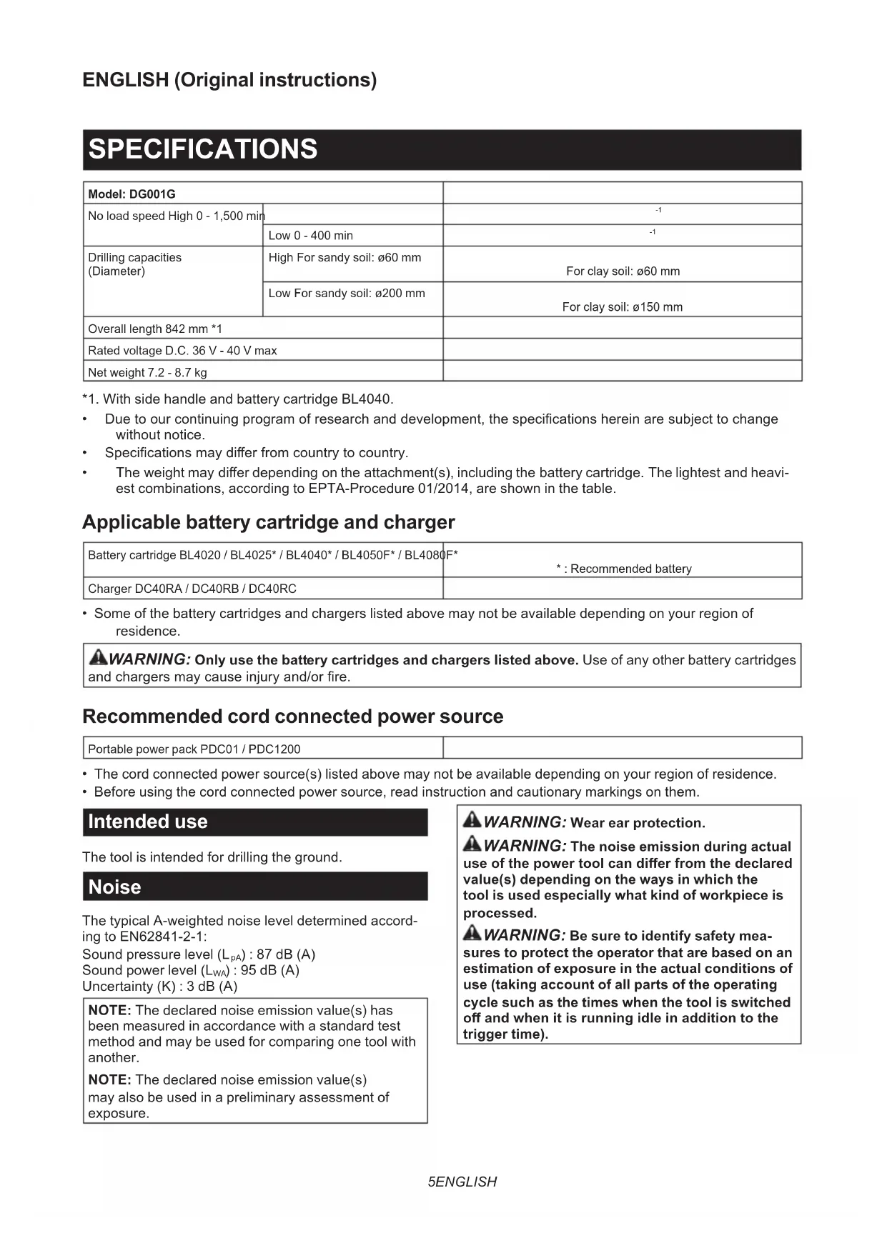
- Specicationsmaydierfromcountrytocountry.
- Theweightmaydierdependingontheattachment(s),includingthebatterycartridge.Thelightestandheavi- est combinations, according to EPTA-Procedure 01/2014, are shown in the table. Applicable battery cartridge and charger Battery cartridge BL4020 / BL4025* / BL4040* / BL4050F* / BL4080F*
- : Recommended battery Charger DC40RA / DC40RB / DC40RC
- Some of the battery cartridges and chargers listed above may not be available depending on your region of residence.
WARNING: Only use the battery cartridges and chargers listed above. Use of any other battery cartridges
andchargersmaycauseinjuryand/orre. Recommended cord connected power source Portable power pack PDC01 / PDC1200
- The cord connected power source(s) listed above may not be available depending on your region of residence.
- Before using the cord connected power source, read instruction and cautionary markings on them. Intended use The tool is intended for drilling the ground. Noise The typical A-weighted noise level determined accord- ing to EN62841-2-1: Sound pressure level (L
) : 95 dB (A) Uncertainty (K) : 3 dB (A) NOTE: The declared noise emission value(s) has been measured in accordance with a standard test method and may be used for comparing one tool with another. NOTE: The declared noise emission value(s) may also be used in a preliminary assessment of exposure.
WARNING: Wear ear protection.
WARNING: The noise emission during actual
use of the power tool can dier from the declared value(s) depending on the ways in which the tool is used especially what kind of workpiece is processed.
WARNING: Be sure to identify safety mea-
sures to protect the operator that are based on an estimation of exposure in the actual conditions of use (taking account of all parts of the operating cycle such as the times when the tool is switched o and when it is running idle in addition to the trigger time).6 ENGLISH Vibration The vibration total value (tri-axial vector sum) deter- mined according to EN62841-2-1: Work mode: drilling into metal Vibration emission (a h,D ) : 2.5 m/s
NOTE: The declared vibration total value(s) has been measured in accordance with a standard test method and may be used for comparing one tool with another. NOTE: The declared vibration total value(s) may also be used in a preliminary assessment of exposure.
WARNING: The vibration emission during
actual use of the power tool can dier from the declared value(s) depending on the ways in which the tool is used especially what kind of workpiece is processed.
WARNING: Be sure to identify safety mea-
sures to protect the operator that are based on an estimation of exposure in the actual conditions of use (taking account of all parts of the operating cycle such as the times when the tool is switched o and when it is running idle in addition to the trigger time). Declarations of Conformity For European countries only The Declarations of conformity are included in Annex A to this instruction manual. SAFETY WARNINGS General power tool safety warnings
WARNING: Read all safety warnings, instruc-
tions, illustrations and specications provided with this power tool. Failure to follow all instructions listedbelowmayresultinelectricshock,reand/or seriousinjury. Save all warnings and instruc- tions for future reference. The term "power tool" in the warnings refers to your mains-operated (corded) power tool or battery-operated (cordless) power tool. Cordless Earth Auger safety warnings
1. Hold the tool with both hands at the intended
handles. Loss of control can cause personal injury.
2. Brace the tool properly before use. This tool
produces a high output torque and without prop- erly bracing the tool during operation, loss of controlmayoccurresultinginpersonalinjury.
3. Hold the power tool by insulated gripping
surfaces, when performing an operation where the digging accessory may contact hidden wiring. Digging accessory contacting a "live" wire may make exposed metal parts of the power tool "live" and could give the operator an electric shock.
4. Never operate at higher speed than the maxi-
mum speed rating of the earth augering bit. At higher speeds, the bit is likely to bend if allowed to rotate freely without contacting the workpiece, resultinginpersonalinjury.
5. Always start earth augering at low speed and
with the earth augering tip in contact with the ground. At higher speeds, the bit is likely to bend if allowed to rotate freely without contacting the ground,resultinginpersonalinjury.
6. Apply pressure only in direct line with the bit
and do not apply excessive pressure. Bits can bend causing breakage or loss of control, resulting inpersonalinjury.
7. The outside diameter of the auger bit must be
within the drilling capacity specied in this instruction manual. Incorrectly sized auger bit cannot be adequately controlled.
8. Always be sure you have a rm footing. Be
sure no one is below when using the tool in high locations.
9. Hold the tool rmly.
10. Keep hands away from rotating parts.
11. Do not leave the tool running. Operate the tool
only when hand-held.
12. Do not touch the auger bit immediately after
operation; it may be extremely hot and could burn your skin.
13. Some material contains chemicals which may
be toxic. Take caution to prevent dust inhala- tion and skin contact. Follow material supplier safety data.
14. If the auger bit cannot be loosened even you
remove the auger pin, use pliers to pull it out. In such a case, pulling out the auger bit by hand mayresultininjurybyitssharpedge.
15. If something wrong with the tool such as
abnormal sounds, stop operating immediately and ask your local Makita Service Center for repair.
16. Before operation, make sure that there is no
buried object such as electric pipe, water pipe or gas pipe in the ground. Otherwise, the tool may touch them, resulting an electric shock, elec- trical leakage or gas leak. SAVE THESE INSTRUCTIONS.
WARNING: DO NOT let comfort or familiarity
with product (gained from repeated use) replace strict adherence to safety rules for the subject product. MISUSE or failure to follow the safety rules stated in this instruction manual may cause serious personal injury.7 ENGLISH Important safety instructions for battery cartridge
1. Before using battery cartridge, read all instruc-
tions and cautionary markings on (1) battery charger, (2) battery, and (3) product using battery.
2. Do not disassemble or tamper with the battery
cartridge.Itmayresultinare,excessiveheat, or explosion.
3. If operating time has become excessively
shorter, stop operating immediately. It may result in a risk of overheating, possible burns and even an explosion.
4. If electrolyte gets into your eyes, rinse them
out with clear water and seek medical atten- tion right away. It may result in loss of your eyesight.
5. Do not short the battery cartridge:
(1) Do not touch the terminals with any con- ductive material. (2) Avoid storing battery cartridge in a con- tainer with other metal objects such as nails, coins, etc. (3) Do not expose battery cartridge to water or rain. A battery short can cause a large current ow, overheating, possible burns and even a breakdown.
6. Do not store and use the tool and battery car-
tridge in locations where the temperature may reach or exceed 50 °C (122 °F).
7. Do not incinerate the battery cartridge even if
it is severely damaged or is completely worn out. The battery cartridge can explode in a re.
8. Do not nail, cut, crush, throw, drop the battery
cartridge, or hit against a hard object to the battery cartridge. Such conduct may result in a re,excessiveheat,orexplosion.
9. Do not use a damaged battery.
10. The contained lithium-ion batteries are subject
to the Dangerous Goods Legislation require- ments. For commercial transports e.g. by third parties, forwarding agents, special requirement on pack- aging and labeling must be observed. For preparation of the item being shipped, consult- ing an expert for hazardous material is required. Please also observe possibly more detailed national regulations. Tapeormaskoopencontactsandpackupthe battery in such a manner that it cannot move around in the packaging.
11. When disposing the battery cartridge, remove
it from the tool and dispose of it in a safe place. Follow your local regulations relating to disposal of battery.
12. Use the batteries only with the products
specied by Makita. Installing the batteries to non-compliantproductsmayresultinare,exces- sive heat, explosion, or leak of electrolyte.
13. If the tool is not used for a long period of time,
the battery must be removed from the tool.
14. During and after use, the battery cartridge may
take on heat which can cause burns or low temperature burns. Pay attention to the han- dling of hot battery cartridges.
15. Do not touch the terminal of the tool imme-
diately after use as it may get hot enough to cause burns.
16. Do not allow chips, dust, or soil stuck into the
terminals, holes, and grooves of the battery cartridge.Itmaycauseheating,catchingre, burst and malfunction of the tool or battery car- tridge,resultinginburnsorpersonalinjury.
17. Unless the tool supports the use near
high-voltage electrical power lines, do not use the battery cartridge near a high-voltage elec- trical power lines. It may result in a malfunction or breakdown of the tool or battery cartridge.
18. Keep the battery away from children.
SAVE THESE INSTRUCTIONS. CAUTION: Only use genuine Makita batteries. Use of non-genuine Makita batteries, or batteries that have been altered, may result in the battery bursting causingres,personalinjuryanddamage.Itwill also void the Makita warranty for the Makita tool and charger. Tips for maintaining maximum battery life
1. Charge the battery cartridge before completely
discharged. Always stop tool operation and charge the battery cartridge when you notice less tool power.
2. Never recharge a fully charged battery car-
tridge. Overcharging shortens the battery service life.
3. Charge the battery cartridge with room tem-
perature at 10 °C - 40 °C (50 °F - 104 °F). Let a hot battery cartridge cool down before charging it.
4. When not using the battery cartridge, remove
it from the tool or the charger.
5. Charge the battery cartridge if you do not use
it for a long period (more than six months).8 ENGLISH INITIAL SETTING CAUTION: Always be sure that the tool is switched o and the battery cartridge is removed before carrying out any work on the tool. PARTS DESCRIPTION ►Fig.1 1 Main tool 2 Front handle 3 Side handle 4 Reaction receiver 5 Bit adapter 6 Chuck key 7 Bolt 8 Wrench Specications of the bolt / wrench - Nominal diameter of the bolt Wrench size (H) A M 12 10 mm B M 8 6 mm C M 6 5 mm NOTE: The type of the bit adapter varies depending on the country. Setting up the tool CAUTION: Always be sure that the side handle and the reaction receiver are installed securely before operation. NOTICE: Do not over tighten the bolts. It may damage the tool. Installing the side handle Removetheboltsshowninthegurefromthetool. The removed bolt is not needed for this tool if you want to use this tool as a cordless earth auger. Keep the bolts so that they are not lost. ►Fig.2: 1. Bolt Place the side handle on the tool. Tighten the all four bolts temporarily, and then securely tighten the bolts using the wrench. ►Fig.3: 1. Side handle 2. Bolt A 3. Bolt B Installing the reaction receiver Place the reaction receiver so that the bar of the reac- tion receiver comes to the left side of the operator. Adjustthepositionofthereactionreceiversothatthe axis of the drill chuck is in the center of the operator's body. Fastentheboltsrmly. ►Fig.4: 1. Bar of the reaction receiver 2. Bolt C FUNCTIONAL DESCRIPTION CAUTION: Always be sure that the tool is switched o and the battery cartridge is removed before adjusting or checking function on the tool. Indicating the remaining battery capacity Press the check button on the battery cartridge to indi- cate the remaining battery capacity. The indicator lamps light up for a few seconds. ►Fig.5: 1. Indicator lamps 2. Check button Indicator lamps Remaining capacity Lighted O Blinking 75% to 100% 50% to 75% 25% to 50% 0% to 25% Charge the battery. The battery may have malfunctioned. NOTE: Depending on the conditions of use and the ambienttemperature,theindicationmaydierslightly from the actual capacity. NOTE:Therst(farleft)indicatorlampwillblinkwhen the battery protection system works. Tool / battery protection system The tool is equipped with a tool/battery protection system. This systemautomaticallycutsopowertothemotortoextendtool and battery life. The tool will automatically stop during operation if the tool or battery is placed under one of the following conditions: Overload protection When the tool/battery is operated in a manner that causes it to draw an abnormally high current, the tool stops automatically. In thissituation,turnthetooloandstoptheapplicationthatcaused the tool to become overloaded. Then turn the tool on to restart. Overheat protection When the tool/battery is overheated, the tool stops automatically. In this situation, let the tool/battery cool before turning the tool on again. Overdischarge protection When the battery capacity is not enough, the tool stops automatically. In this case, remove the battery from the tool and charge the battery.9 ENGLISH Main power switch
WARNING: Always turn o the main power
switch when not in use. To stand by the tool, press the main power button until themainpowerlamplightsup.Toturno,pressthe main power button again. ►Fig.6: 1. Main power button NOTE:Thistoolemploystheautopower-ofunction. To avoid unintentional start up, the main power switch will automatically shut down when the switch trigger is not pulled for a certain period after the main power switch is turned on. Switch action CAUTION: Before installing the battery car- tridge into the tool, always check to see that the switch trigger actuates properly and returns to the "OFF" position when released. ►Fig.7: 1. Switch trigger To start the tool, pull the switch trigger with the main power switch on. Tool speed is increased by increas- ing pressure on the switch trigger. Release the switch trigger to stop. NOTE: The tool automatically stops if you keep pull- ing the switch trigger for about 6 minutes. Lighting up the front lamp CAUTION: Do not look in the light or see the source of light directly. ►Fig.8: 1. Lamp Pull the switch trigger to light up the lamp. The lamp keeps on lighting while the switch trigger is being pulled. The lamp goes out approximately 10 seconds after releasing the switch trigger. NOTE: When the tool is overheated, the tool stops automaticallyandthelampstartsashing.Inthis case,releasetheswitchtrigger.Thelampturnsoin 5 minute(s). NOTE:Useadryclothtowipethedirtothelensof the lamp. Be careful not to scratch the lens of lamp, or it may lower the illumination. Reversing switch action CAUTION: Always check the direction of rotation before operation. CAUTION: Use the reversing switch only after the tool comes to a complete stop. Changing the direction of rotation before the tool stops may dam- age the tool. CAUTION: When not operating the tool, always set the reversing switch lever to the neu- tral position. This tool has a reversing switch to change the direction of rotation. Depress the reversing switch lever from the A side for clockwise rotation or from the B side for coun- terclockwise rotation. When the reversing switch lever is in the neutral posi- tion, the switch lever cannot be pulled. ►Fig.9: 1. Reversing switch lever Automatic speed change function This tool has "high speed mode" and "high torque mode". The tool automatically changes the operation mode depending on the work load. When the work load is low, the tool will run in the "high speed mode" for quicker operation. When the work load is high, the tool will run in the "high torque mode" for powerful operation. ►Fig.10: 1. Mode indicator The mode indicator lights up in green when the tool is running in "high torque mode". If the tool is operated with excessive load, the mode indicator will blink in green. The mode indicator stops blinkingandthenlightsuporturnsoifyoureducethe load on the tool. Mode indicator status Operation mode On O Blinking High speed mode High torque mode Overload alert Speed change NOTICE: Use the speed change knob only after the tool comes to a complete stop. Changing the tool speed before the tool stops may damage the tool. NOTICE: Always set the speed change knob carefully into the correct position. If you operate the tool with the speed change knob positioned half- way between the position 1 and the position 2, the tool may be damaged. Two speed ranges can be preselected with the speed change knob. To change the speed, depress the lock button and turn the speed change knob so that the pointer points to the position 1 for low speed or the position 2 for high speed. ►Fig.11: 1. Lock button 2. Pointer 3. Speed change knob Torque limiter The torque limiter will actuate when a certain torque level is reached at the low speed setting (position 1). The motor will disengage from the output shaft. When this happens, the tool bit will stop turning. To restart the tool, lift the tool bit out of the hole and then pull the switch trigger again.10 ENGLISH Electronic function Electric brake This tool is equipped with an electric brake. If the tool consistently fails to quickly cease to function after the switch trigger is released, have the tool serviced at a Makita service center. Soft start feature This function allows the smooth start-up of the tool by limiting the start-up torque. ASSEMBLY Installing or removing battery cartridge CAUTION: Always switch o the tool before installing or removing of the battery cartridge. CAUTION: Hold the tool and the battery car- tridge rmly when installing or removing battery cartridge. Failure to hold the tool and the battery cartridgermlymaycausethemtoslipoyourhands and result in damage to the tool and battery cartridge andapersonalinjury. ►Fig.12: 1. Red indicator 2. Button 3. Battery cartridge To remove the battery cartridge, slide it from the tool while sliding the button on the front of the cartridge. To install the battery cartridge, align the tongue on the battery cartridge with the groove in the housing and slip it into place. Insert it all the way until it locks in place with a little click. If you can see the red indicator as showninthegure,itisnotlockedcompletely. CAUTION: Always install the battery cartridge fully until the red indicator cannot be seen. If not, itmayaccidentallyfalloutofthetool,causinginjuryto you or someone around you. CAUTION: Do not install the battery cartridge forcibly. If the cartridge does not slide in easily, it is not being inserted correctly. Mounting the auger bit CAUTION: Always be sure that the tool is switched o and the battery cartridge is removed before carrying out any work on the tool. CAUTION: When installing the bit adapter to the chuck, make sure that the bit adapter is fully inserted. CAUTION: When attaching the auger bit to the bit adapter, make sure that the auger pin is locked and inspect the auger pin for any damages. CAUTION: When carrying the tool, remove the auger bit from the tool. Installing or removing the bit adapter To mount the auger bit, install the bit adapter in advance. To install the bit adapter, place the bit adapter in the chuck as far as it will go. Tighten the chuck by rotating the sleeve by hand. Place the chuck key in the chuck hole and tighten clock- wise. Be sure to tighten all three chuck holes evenly. To remove the bit adapter, turn the chuck key counter- clockwiseinjustonehole,thenloosenthechuckbyhand. ►Fig.13: 1. Chuck key 2. Chuck 3. Sleeve After use, return the chuck key to the key holder on the tool as illustrated. ►Fig.14: 1. Key holder Mounting the auger bit on the bit adapter NOTE: The shape and mechanism of the auger bit and the auger pin may vary depending on your auger bit. Align the hole on the bit adapter with the hole on the auger bit. Put the auger bit onto the bit adapter. ►Fig.15: 1. Auger bit 2. Bit adapter Fix the auger bit with the auger pin and the safety lock. ►Fig.16: 1. Auger pin 2. Safety lock OPERATION CAUTION: This is a powerful tool which gen- erates high torque. It is important that the tool is securely held and properly braced. CAUTION: Before operating, check that there is no foreign matter (sand, dirt, etc.) stuck in the openings or moving parts. Work posture Maintaining proper operating position is one of the mostimportantandeectiveproceduresforcontrolling kickback. Keep proper positioning by practicing the following points.
- Position the tool so that the bar of the reaction receiver always contacts on the left side of your waist.
- Grasp the handle and the side handle with both hands.Wrapyourngersaroundthegripping areas, keeping the gripping areas cradled betweenyourthumbsandforengers.
- Keep your back as vertical as possible by bending the legs as required during the digging process.
- Stay alert to the torque reaction force of the tool. Always keep the operating position that you can withstand the torque reaction force. ►Fig.17: 1. Handle 2. Side handle 3. Bar of the reac- tion receiver
WARNING: Avoid improper positioning. Do
not stand too far from the tool. Proper reaction and control may not be achieved in the event of kickback. ►Fig.1811 ENGLISH Digging operation CAUTION: Hold the tool rmly when operat- ing the tool. CAUTION: When leaving the tool, such as during a break, do not leave the tool stabbed in the ground or lean it against a wall. Store the tool in a stable condition. NOTICE: When the rotation speed comes down extremely, reduce the load or stop the tool to avoid the tool damage. NOTICE: Pressing excessively on the tool will not speed up the digging. In fact, this excessive pressure will only serve to damage the tip of the auger bit, decrease the tool performance and shorten the service life of the tool. NOTICE: Avoid digging in material that you suspect contains hidden nails or other things that may cause the auger bit to bind or break. NOTICE: If the tool is operated continuously until the battery cartridge has depleted, allow the tool to rest for 15 minutes before proceeding with a fresh battery.
- Select the speed (high/low) properly depending on the hole diameter and condition of the ground.
- When digging a deep hole or digging in clay soil, do not try to dig at once. Dig the hole by lifting up and down the tool so that the soil in the hole can be discharged.
- If the rotation speed of the tool slows down due to high load operation, lift the tool up little, and move the tool up and down to dig in small steps. When rotating the auger bit in reverse A stuck auger bit can be removed simply by setting the reversing switch to reverse rotation in order to back out. When reversing, brace the tool by your body to prevent a clockwise reaction. ►Fig.19 CAUTION: Hold the tool rmly. The tool may backoutabruptlyandcauseaninjury. MAINTENANCE CAUTION: Always be sure that the tool is switched o and the battery cartridge is removed before attempting to perform inspection or maintenance. NOTICE: Never use gasoline, benzine, thinner, alcohol or the like. Discoloration, deformation or cracks may result. To maintain product SAFETY and RELIABILITY, repairs,anyothermaintenanceoradjustmentshould be performed by Makita Authorized or Factory Service Centers, always using Makita replacement parts. OPTIONAL ACCESSORIES CAUTION: These accessories or attachments are recommended for use with your Makita tool specied in this manual. The use of any other accessories or attachments might present a risk of injurytopersons.Onlyuseaccessoryorattachment for its stated purpose. If you need any assistance for more details regard- ing these accessories, ask your local Makita Service Center.
- Makita genuine battery and charger NOTE: Some items in the list may be included in the tool package as standard accessories. They may dierfromcountrytocountry.12 FRANÇAIS FRANÇAIS (Instructions originales) SPÉCIFICATIONS Modèle : DG001G Vitesse à vide Élevée 0 - 1 500 min