HR2470BX40 - Drill MAKITA - Free user manual and instructions
Find the device manual for free HR2470BX40 MAKITA in PDF.
Download the instructions for your Drill in PDF format for free! Find your manual HR2470BX40 - MAKITA and take your electronic device back in hand. On this page are published all the documents necessary for the use of your device. HR2470BX40 by MAKITA.
USER MANUAL HR2470BX40 MAKITA
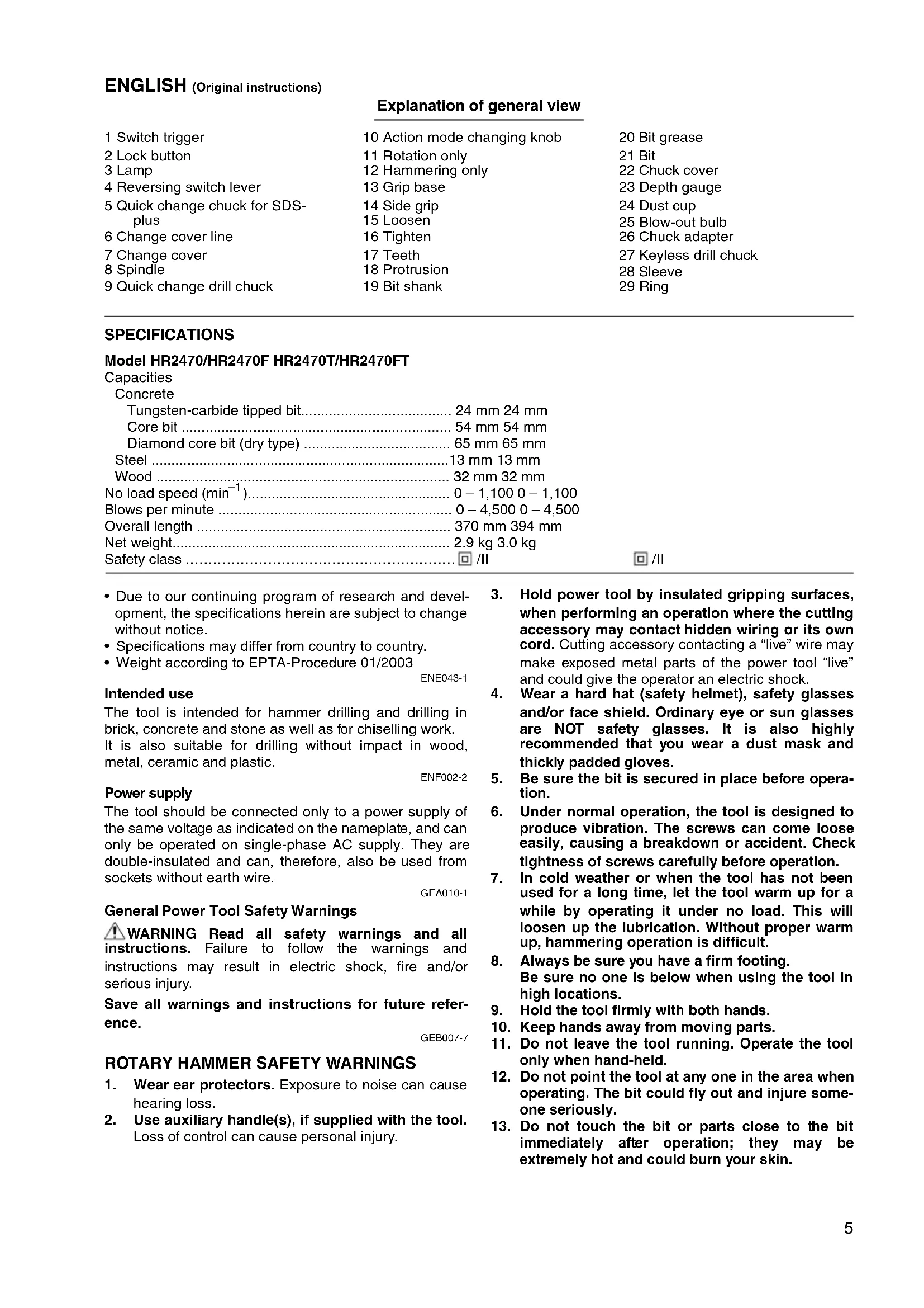
- Due to our continuing program of research and devel- opment, the specifications herein are subject to change without notice.
- Specifications may differ from country to country.
- Weight according to EPTA-Procedure 01/2003 ENE043-1 Intended use The tool is intended for hammer drilling and drilling in brick, concrete and stone as well as for chiselling work. It is also suitable for drilling without impact in wood, metal, ceramic and plastic. ENF002-2 Power supply The tool should be connected only to a power supply of the same voltage as indicated on the nameplate, and can only be operated on single-phase AC supply. They are double-insulated and can, therefore, also be used from sockets without earth wire. GEA010-1 General Power Tool Safety Warnings WARNING Read all safety warnings and all instructions. Failure to follow the warnings and instructions may result in electric shock, fire and/or serious injury. Save all warnings and instructions for future refer- ence. GEB007-7
ROTARY HAMMER SAFETY WARNINGS
1. Wear ear protectors. Exposure to noise can cause
2. Use auxiliary handle(s), if supplied with the tool.
Loss of control can cause personal injury.
3. Hold power tool by insulated gripping surfaces,
when performing an operation where the cutting accessory may contact hidden wiring or its own cord. Cutting accessory contacting a “live” wire may make exposed metal parts of the power tool “live” and could give the operator an electric shock.
4. Wear a hard hat (safety helmet), safety glasses
and/or face shield. Ordinary eye or sun glasses are NOT safety glasses. It is also highly recommended that you wear a dust mask and thickly padded gloves.
5. Be sure the bit is secured in place before opera-
6. Under normal operation, the tool is designed to
produce vibration. The screws can come loose easily, causing a breakdown or accident. Check tightness of screws carefully before operation.
7. In cold weather or when the tool has not been
used for a long time, let the tool warm up for a while by operating it under no load. This will loosen up the lubrication. Without proper warm up, hammering operation is difficult.
8. Always be sure you have a firm footing.
Be sure no one is below when using the tool in high locations.
9. Hold the tool firmly with both hands.
10. Keep hands away from moving parts.
11. Do not leave the tool running. Operate the tool
only when hand-held.
12. Do not point the tool at any one in the area when
operating. The bit could fly out and injure some- one seriously.
13. Do not touch the bit or parts close to the bit
immediately after operation; they may be extremely hot and could burn your skin.6
14. Some material contains chemicals which may be
toxic. Take caution to prevent dust inhalation and skin contact. Follow material supplier safety data. SAVE THESE INSTRUCTIONS.
DO NOT let comfort or familiarity with product (gained from repeated use) replace strict adherence to safety rules for the subject product. MISUSE or failure to follow the safety rules stated in this instruc- tion manual may cause serious personal injury. FUNCTIONAL DESCRIPTION CAUTION:
- Always be sure that the tool is switched off and unplugged before adjusting or checking function on the tool. Switch action (Fig. 1) CAUTION:
- Before plugging in the tool, always check to see that the switch trigger actuates properly and returns to the “OFF” position when released. To start the tool, simply pull the switch trigger. Tool speed is increased by increasing pressure on the switch trigger. Release the switch trigger to stop. For continuous operation, pull the switch trigger and then push in the lock button. To stop the tool from the locked position, pull the switch trigger fully, then release it. Lighting up the lamps (Fig. 2) For Model HR2470F/2470FT CAUTION:
- Do not look in the light or see the source of light directly. To turn on the lamp, pull the trigger. Release the trigger to turn it off. NOTE:
- Use a dry cloth to wipe the dirt off the lens of lamp. Be careful not to scratch the lens of lamp, or it may lower the illumination. Reversing switch action (Fig. 3) CAUTION:
- Always check the direction of rotation before operation.
- Use the reversing switch only after the tool comes to a complete stop. Changing the direction of rotation before the tool stops may damage the tool.
- If the switch trigger can not be depressed, check to see that the reversing switch is fully set to position (A side) or (B side). This tool has a reversing switch to change the direction of rotation. Move the reversing switch lever to the posi- tion (A side) for clockwise rotation or the position (B side) for counterclockwise rotation. Changing the quick change chuck for SDS-plus For Model HR2470T/HR2470FT The quick change chuck for SDS-plus can be easily exchanged for the quick change drill chuck. Removing the quick change chuck for SDS-plus (Fig. 4) CAUTION:
- Before removing the quick change chuck for SDS-plus, always remove the bit. Grasp the change cover of the quick change chuck for SDS-plus and turn in the direction of the arrow until the change cover line moves from the symbol to the symbol. Pull forcefully in the direction of the arrow. Attaching the quick change drill chuck (Fig. 5) Check the line of the quick change drill chuck shows the symbol. Grasp the change cover of the quick change drill chuck and set the line to the symbol. Place the quick change drill chuck on the spindle of the tool. Grasp the change cover of the quick change drill chuck and turn the change cover line to the symbol until a click can clearly be heard. Selecting the action mode Rotation with hammering (Fig. 6) For drilling in concrete, masonry, etc., depress the lock button and rotate the action mode changing knob to the symbol. Use a tungsten-carbide tipped bit. Rotation only (Fig. 7) For drilling in wood, metal or plastic materials, depress the lock button and rotate the action mode changing knob to the m symbol. Use a twist drill bit or wood bit. Hammering only (Fig. 8) For chipping, scaling or demolition operations, depress the lock button and rotate the action mode changing knob to the symbol. Use a bull point, cold chisel, scal- ing chisel, etc. CAUTION:
- Do not rotate the action mode changing knob when the tool is running under load. The tool will be damaged.
- To avoid rapid wear on the mode change mechanism, be sure that the action mode changing knob is always positively located in one of the three action mode positions. Torque limiter The torque limiter will actuate when a certain torque level is reached. The motor will disengage from the output shaft. When this happens, the bit will stop turning. CAUTION:
- As soon as the torque limiter actuates, switch off the tool immediately. This will help prevent premature wear of the tool.
- Bits such as hole saw, which tend to pinch or catch easily in the hole, are not appropriate for this tool. This is because they will cause the torque limiter to actuate too frequently. ASSEMBLY CAUTION:
- Always be sure that the tool is switched off and unplugged before carrying out any work on the tool. Side grip (auxiliary handle) (Fig. 9) CAUTION:
- Always use the side grip to ensure operating safety. Install the side grip so that the teeth on the grip fit in between the protrusions on the tool barrel. Then tighten the grip by turning clockwise at the desired position. It may be swung 360° so as to be secured at any position.7 Bit grease Coat the bit shank head beforehand with a small amount of bit grease (about 0.5–1g). This chuck lubrication assures smooth action and longer service life. Installing or removing the bit Clean the bit shank and apply bit grease before installing the bit. (Fig. 10) Insert the bit into the tool. Turn the bit and push it in until it engages. (Fig. 11) After installing, always make sure that the bit is securely held in place by trying to pull it out. To remove the bit, pull the chuck cover down all the way and pull the bit out. (Fig. 12) Bit angle (when chipping, scaling or demolishing) The bit can be secured at the desired angle. To change the bit angle, depress the lock button and rotate the action mode changing knob to the O symbol. Tur n t he bit to the desired angle. (Fig. 13) Depress the lock button and rotate the action mode changing knob to the symbol. Then make sure that the bit is securely held in place by turning it slightly. (Fig. 14) Depth gauge (Fig. 15) The depth gauge is convenient for drilling holes of uni- form depth. Loosen the side grip and insert the depth gauge into the hole in the side grip. Adjust the depth gauge to the desired depth and tighten the side grip. NOTE:
- The depth gauge cannot be used at the position where the depth gauge strikes against the gear housing. Dust cup (Fig. 16) Use the dust cup to prevent dust from falling over the tool and on yourself when performing overhead drilling operations. Attach the dust cup to the bit as shown in Fig. 16. The size of bits which the dust cup can be attached to is as follows.
OPERATION Hammer drilling operation (Fig. 17) Set the action mode changing knob to the symbol. Position the bit at the desired location for the hole, then pull the switch trigger. Do not force the tool. Light pressure gives best results. Keep the tool in position and prevent it from slipping away from the hole. Do not apply more pressure when the hole becomes clogged with chips or particles. Instead, run the tool at an idle, then remove the bit partially from the hole. By repeating this several times, the hole will be cleaned out and normal drilling may be resumed. CAUTION:
- There is tremendous and sudden twisting force exerted on the tool/bit at the time of hole break-through, when the hole becomes clogged with chips and particles, or when striking reinforcing rods embedded in the concrete. Always use the side grip (auxiliary handle) and firmly hold the tool by both side grip and switch handle during operations. Failure to do so may result in the loss of control of the tool and potentially severe injury. NOTE:
- Eccentricity in the bit rotation may occur while operat- ing the tool with no load. The tool automatically centers itself during operation. This does not affect the drilling precision. Blow-out bulb (optional accessory) (Fig. 18) After drilling the hole, use the blow-out bulb to clean the dust out of the hole. Chipping/Scaling/Demolition (Fig. 19) Set the action mode changing knob to the symbol. Hold the tool firmly with both hands. Turn the tool on and apply slight pressure on the tool so that the tool will not bounce around, uncontrolled. Pressing very hard on the tool will not increase the efficiency. Drilling in wood or metal (Fig. 20, 21, 22 & 23) For Model HR2470/HR2470F Use the optional drill chuck assembly. When installing it, refer to “Installing or removing the bit” described on the previous page. For Model HR2470T/HR2470FT Use the quick change drill chuck as standard equipment. When installing it, refer to “Changing the quick change chuck for SDS-plus” described on the previous page. Hold the ring and turn the sleeve counterclockwise to open the chuck jaws. Place the bit in the chuck as far as it will go. Hold the ring firmly and turn the sleeve clockwise to tighten the chuck. To remove the bit, hold the ring and turn the sleeve counterclockwise. Set the action mode changing knob to the m symbol. You can drill up to 13 mm diameter in metal and up to 32 mm diameter in wood. CAUTION:
- Never use “rotation with hammering” when the quick change drill chuck is installed on the tool. The quick change drill chuck may be damaged. Also, the drill chuck will come off when reversing the tool.
- Pressing excessively on the tool will not speed up the drilling. In fact, this excessive pressure will only serve to damage the tip of your bit, decrease the tool performance and shorten the service life of the tool.
- There is a tremendous twisting force exerted on the tool/bit at the time of hole breakthrough. Hold the tool firmly and exert care when the bit begins to break through the workpiece.
- A stuck bit can be removed simply by setting the reversing switch to reverse rotation in order to back out. However, the tool may back out abruptly if you do not hold it firmly.
- Always secure small workpieces in a vise or similar hold-down device. Bit diameter Dust cup 5 6 mm – 14.5 mm Dust cup 9 12 mm – 16 mm8 Diamond core drilling When performing diamond core drilling operations, always set the change lever to the m position to use “rota- tion only” action. CAUTION:
- If performing diamond core drilling operations using “rotation with hammering” action, the diamond core bit may be damaged. MAINTENANCE CAUTION:
- Always be sure that the tool is switched off and unplugged before attempting to perform inspection or maintenance.
- Never use gasoline, benzine, thinner, alcohol or the like. Discoloration, deformation or cracks may result. To maintain product SAFETY and RELIABILITY, repairs, carbon brush inspection and replacement, any other maintenance or adjustment should be performed by Makita Authorized Service Centers, always using Makita replacement parts. OPTIONAL ACCESSORIES CAUTION:
- These accessories or attachments are recommended for use with your Makita tool specified in this manual. The use of any other accessories or attachments might present a risk of injury to persons. Only use accessory or attachment for its stated purpose. If you need any assistance for more details regarding these accessories, ask your local Makita Service Center.
- Dust extractor attachment
- Plastic carrying case
- Keyless drill chuck NOTE:
- Some items in the list may be included in the tool pack- age as standard accessories. They may differ from country to country. ENG905-1 Noise The typical A-weighted noise level determined according to EN60745: Sound pressure level (L
): 90 dB (A) Sound power level (L
): 101 dB (A) Uncertainty (K): 3 dB (A) Wear ear protection ENG900-1 Vibration The vibration total value (tri-axial vector sum) determined according to EN60745: Work mode: chiselling Vibration emission (a h, CHeq ): 12.5 m/s
Work mode: hammer drilling into concrete Vibration emission (a h, HD ): 15.5 m/s
Work mode: drilling into metal Vibration emission (a h, D ): 4.5 m/s
- The declared vibration emission value has been mea- sured in accordance with the standard test method and may be used for comparing one tool with another.
- The declared vibration emission value may also be used in a preliminary assessment of exposure.
- The vibration emission during actual use of the power tool can differ from the declared emission value depending on the ways in which the tool is used.
- Be sure to identify safety measures to protect the oper- ator that are based on an estimation of exposure in the actual conditions of use (taking account of all parts of the operating cycle such as the times when the tool is switched off and when it is running idle in addition to the trigger time).